EP0103555A1 - Verriegelungsvorrichtung für einen Kolben - Google Patents
Verriegelungsvorrichtung für einen Kolben Download PDFInfo
- Publication number
- EP0103555A1 EP0103555A1 EP83850217A EP83850217A EP0103555A1 EP 0103555 A1 EP0103555 A1 EP 0103555A1 EP 83850217 A EP83850217 A EP 83850217A EP 83850217 A EP83850217 A EP 83850217A EP 0103555 A1 EP0103555 A1 EP 0103555A1
- Authority
- EP
- European Patent Office
- Prior art keywords
- piston
- cylinder
- wedge means
- piston rod
- contact surface
- Prior art date
- Legal status (The legal status is an assumption and is not a legal conclusion. Google has not performed a legal analysis and makes no representation as to the accuracy of the status listed.)
- Granted
Links
- 239000012530 fluid Substances 0.000 claims abstract description 12
- 230000004913 activation Effects 0.000 abstract description 5
- 230000003213 activating effect Effects 0.000 abstract 1
- 230000002040 relaxant effect Effects 0.000 description 2
- 230000003247 decreasing effect Effects 0.000 description 1
- 230000000694 effects Effects 0.000 description 1
- 230000003472 neutralizing effect Effects 0.000 description 1
Images
Classifications
-
- F—MECHANICAL ENGINEERING; LIGHTING; HEATING; WEAPONS; BLASTING
- F15—FLUID-PRESSURE ACTUATORS; HYDRAULICS OR PNEUMATICS IN GENERAL
- F15B—SYSTEMS ACTING BY MEANS OF FLUIDS IN GENERAL; FLUID-PRESSURE ACTUATORS, e.g. SERVOMOTORS; DETAILS OF FLUID-PRESSURE SYSTEMS, NOT OTHERWISE PROVIDED FOR
- F15B15/00—Fluid-actuated devices for displacing a member from one position to another; Gearing associated therewith
- F15B15/20—Other details, e.g. assembly with regulating devices
- F15B15/26—Locking mechanisms
- F15B15/262—Locking mechanisms using friction, e.g. brake pads
Definitions
- This invention relates to a pressure fluid actuated piston cylinder device in which a piston is sealingly guided in a cylinder and a piston rod united with the piston extends out of the cylinder through one of the cylinder end walls.
- a releaseable piston rod locking mechanism is disposed in the cylinder end wall and comprises first and second wedge means arranged to frictionally engage the piston rod, and a spring means continuously biassing the wedge means into locking engagement with piston rod.
- Piston-cylinder devices of the above type find use in applications where safety demands are high as regards avoidance of uncontrolled piston movement at, for instance, hose breakage.
- a piston cylinder device having a built-in piston locking mechanism it is also possible to stop and lock the piston and piston rod in predetermined positions.
- conical piston rod engaging friction ring is encircled by an annular activation member which is spring. biassed in its friction ring engaging direction and selectively acted upon by pressure fluid in the opposite direction for releasing the piston rod.
- the main object of the invention is to accomplish a piston cylinder device in which the locking means will generate a powerful enough locking action and in which the locking means does not cause increased outer dimensions of the piston cylinder device.
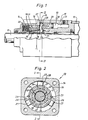
- the piston-cylinder device shown in the drawing figures comprises a cylinder 10, a piston (not shown) sealingly guided in the cylinder and a piston rod 11 which extends out of the cylinder 10 through the end wall 13 of the cylinder 10.
- the cylinder end wall 13 comprises an outer section 14 and an inner section 15.
- a piston rod clamping unit 17 comprises three conical piston rod 11 engaging friction segments 18, an axially displaceable wedge ring 19 surrounding the friction segments 18, and a spring means 20.
- the latter which consists of a number of Belleville-type spring washers, acts between the outer cylinder end wall section 14 and the wedge ring 19, thereby biassing the latter in the friction segment engaging direction.
- Each of the friction segments are provided with a lining 21 for improved frictional engagement with the piston rod 11. Between the segments 18 there are radial clearances 22 for making sure that the radial grip on the piston rod 11 is not jeopardized by contact between the friction segments themselves.
- the wedge ring 19 is locked against rotation by means of two axially extending keys 23 mounted diametrically opposite each other in the end wall section 14.
- Wire inserts 24 are located in axial grooves in the cooperating conical surfaces of the friction segments 18 and the wedge ring 19 in order to prevent the segments to rotate and also to prevent the piston rod 11 from being rotated when locked.
- annular space 26 Between the cylinder end wall sections 14, 15 there is an annular space 26 in which three equally spaced levers 27 are supported. Each of these levers 27 is guided in a radial recess 28 in the inner cylinder wall section 15.
- a ring piston 29 is sealingly guided in an annular chamber 30 in the inner end wall section 15.
- the annular chamber 30 is selectively supplied with pressure fluid through a passage 31.
- the piston 29 is intended to counteract and neutralize the'force developed by the Belleville springs 20 and to move the annular wedge ring 19 off the segments 18, thereby relaxing the clamping unit 17 and permitting movement of the piston rod 11.
- Each of the levers 27 has a first contact surface 33 engaging two immovable fulcrum forming rings 34, 35, a second contact surface 36 facing the same direction as the first contact surface 33 for engaging the ring piston 29, and a third contact surface 37 located right in between the first and second contact surfaces 33, 36 and facing the opposite direction.
- the third contact surface 37 abuts against the wedge ring 19. Due to the lever arrangement, the movement of piston 29 is transferred to the wedge ring 19 at half the speed but twice the power. This means that a fairly small release piston may be used-to neutralize a strong activation spring 20.
- Fig 1 the locking mechanism is shown in its released position. Pressure fluid is supplied to chamber 30 via passage 31, and the piston 29 has moved to its left hand position. The piston movement has been transferred to the annular wedge ring 19 by the levers 27. The force developed by the piston 29 is amplified by 100% by the levers 27.
Landscapes
- Engineering & Computer Science (AREA)
- Physics & Mathematics (AREA)
- Fluid Mechanics (AREA)
- Mechanical Engineering (AREA)
- General Engineering & Computer Science (AREA)
- Actuator (AREA)
Applications Claiming Priority (2)
| Application Number | Priority Date | Filing Date | Title |
|---|---|---|---|
| SE8204775A SE441468B (sv) | 1982-08-20 | 1982-08-20 | Losbar lasningsanordning for en tryckmediemanovrerad kolvcylinder |
| SE8204775 | 1982-08-20 |
Publications (2)
| Publication Number | Publication Date |
|---|---|
| EP0103555A1 true EP0103555A1 (de) | 1984-03-21 |
| EP0103555B1 EP0103555B1 (de) | 1986-02-26 |
Family
ID=20347575
Family Applications (1)
| Application Number | Title | Priority Date | Filing Date |
|---|---|---|---|
| EP83850217A Expired EP0103555B1 (de) | 1982-08-20 | 1983-08-19 | Verriegelungsvorrichtung für einen Kolben |
Country Status (3)
| Country | Link |
|---|---|
| EP (1) | EP0103555B1 (de) |
| DE (1) | DE3362306D1 (de) |
| SE (1) | SE441468B (de) |
Cited By (19)
| Publication number | Priority date | Publication date | Assignee | Title |
|---|---|---|---|---|
| DE3510643A1 (de) * | 1985-03-23 | 1986-09-25 | Sitema Gesellschaft für Sicherheitstechnik und Maschinenbau mbH, 7500 Karlsruhe | Klemmkopf |
| US4733602A (en) * | 1986-03-17 | 1988-03-29 | Wabco Ltd. | Hydraulic brake actuator with parking brake |
| DE4126897A1 (de) * | 1991-08-14 | 1993-02-18 | Rexroth Mannesmann Gmbh | Hydraulisches klemmsystem |
| EP0589863A1 (de) * | 1992-09-15 | 1994-03-30 | Hoerbiger Ventilwerke Aktiengesellschaft | Hydraulikzylinder |
| DE4421861A1 (de) * | 1993-10-07 | 1995-04-20 | Hoerbiger Ventilwerke Ag | Hydraulikzylinder |
| WO1997030291A1 (en) * | 1996-02-14 | 1997-08-21 | Ready, S.R.L. | A device for locking the sliding of the rod of a linear actuator and a linear actuator provided with the device |
| WO2000058632A1 (en) * | 1999-03-26 | 2000-10-05 | Parker Hannifin Ab | Piston-cylinder device with piston rod locking means |
| WO2001069091A1 (en) * | 2000-03-16 | 2001-09-20 | Ready S.R.L. | A device and a unit for locking the sliding of the rod of a linear actuator |
| WO2003046388A1 (en) * | 2001-11-26 | 2003-06-05 | Eckhard Polman | Actuator |
| EP1528267A1 (de) * | 2003-10-27 | 2005-05-04 | SITEMA GmbH & Co. KG | Feststellvorrichtung |
| EP1813823A2 (de) | 2006-01-31 | 2007-08-01 | SITEMA GmbH & Co. KG | Klemmvorrichtung |
| EP1726803A3 (de) * | 2005-05-27 | 2008-12-10 | Goodrich Pump & Engine Control Systems, Inc. | Hydraulischer Selbsthaltung für eine Ausgabevorrichtung mit Axialbewegung |
| DE102011112946A1 (de) * | 2011-09-13 | 2013-03-14 | Hema Maschinen- Und Apparateschutz Gmbh | Kraftverstärkung für Klemm- bzw. Bremssysteme |
| CN104791327A (zh) * | 2015-04-02 | 2015-07-22 | 中航飞机股份有限公司西安飞机分公司 | 一种用于钢球锁结构的应急开锁装置 |
| CN106855072A (zh) * | 2017-02-21 | 2017-06-16 | 泉州市海恩德机电科技发展有限公司 | 液压径向锁紧装置 |
| EP3203090A1 (de) * | 2016-02-04 | 2017-08-09 | Tetra Laval Holdings & Finance S.A. | Sperreinheit |
| CN113202838A (zh) * | 2021-05-31 | 2021-08-03 | 徐工集团工程机械股份有限公司道路机械分公司 | 一种分体式机械锁定油缸 |
| CN113883124A (zh) * | 2021-09-30 | 2022-01-04 | 四川大学 | 一种用于高温高压环境模拟舱的底部油缸 |
| CN116441954A (zh) * | 2023-06-16 | 2023-07-18 | 中机生产力促进中心有限公司 | 低速重载直线运动锁紧系统及锁紧操作方法 |
Families Citing this family (4)
| Publication number | Priority date | Publication date | Assignee | Title |
|---|---|---|---|---|
| CN104088850A (zh) * | 2014-07-06 | 2014-10-08 | 上海宏信设备工程有限公司 | 组合式斜锥自锁液压油缸 |
| CN104500501B (zh) * | 2014-12-05 | 2017-01-25 | 四川凌峰航空液压机械有限公司 | 液压浮动卡环锁 |
| CN106438573B (zh) * | 2016-06-30 | 2018-11-20 | 泸州长信液压机械制造有限公司 | 锥套式机械锁紧油缸 |
| CN106050803A (zh) * | 2016-07-29 | 2016-10-26 | 泸州合成液压件有限公司 | 一种锁紧油缸 |
Citations (3)
| Publication number | Priority date | Publication date | Assignee | Title |
|---|---|---|---|---|
| FR761703A (fr) * | 1933-10-05 | 1934-03-26 | élévateur hydro-pneumatique | |
| GB2006340A (en) * | 1977-10-21 | 1979-05-02 | Stratienko A | Locking Device for Hydraulic Actuator |
| DE7931576U1 (de) * | 1979-11-08 | 1981-06-25 | P-H-matic Ges. für pneumatische und hydraulische Antriebe und Steuerungen mbH, 8000 München | Bremseinrichtung für kolbenstangenlose Arbeitszylinder |
Family Cites Families (1)
| Publication number | Priority date | Publication date | Assignee | Title |
|---|---|---|---|---|
| DE2755456A1 (de) * | 1977-12-13 | 1979-06-28 | Bosch Gmbh Robert | Arbeitszylinder |
-
1982
- 1982-08-20 SE SE8204775A patent/SE441468B/sv not_active IP Right Cessation
-
1983
- 1983-08-19 DE DE8383850217T patent/DE3362306D1/de not_active Expired
- 1983-08-19 EP EP83850217A patent/EP0103555B1/de not_active Expired
Patent Citations (3)
| Publication number | Priority date | Publication date | Assignee | Title |
|---|---|---|---|---|
| FR761703A (fr) * | 1933-10-05 | 1934-03-26 | élévateur hydro-pneumatique | |
| GB2006340A (en) * | 1977-10-21 | 1979-05-02 | Stratienko A | Locking Device for Hydraulic Actuator |
| DE7931576U1 (de) * | 1979-11-08 | 1981-06-25 | P-H-matic Ges. für pneumatische und hydraulische Antriebe und Steuerungen mbH, 8000 München | Bremseinrichtung für kolbenstangenlose Arbeitszylinder |
Cited By (30)
| Publication number | Priority date | Publication date | Assignee | Title |
|---|---|---|---|---|
| DE3510643A1 (de) * | 1985-03-23 | 1986-09-25 | Sitema Gesellschaft für Sicherheitstechnik und Maschinenbau mbH, 7500 Karlsruhe | Klemmkopf |
| US4733602A (en) * | 1986-03-17 | 1988-03-29 | Wabco Ltd. | Hydraulic brake actuator with parking brake |
| DE4126897A1 (de) * | 1991-08-14 | 1993-02-18 | Rexroth Mannesmann Gmbh | Hydraulisches klemmsystem |
| EP0589863A1 (de) * | 1992-09-15 | 1994-03-30 | Hoerbiger Ventilwerke Aktiengesellschaft | Hydraulikzylinder |
| DE4421861C2 (de) * | 1993-10-07 | 1999-07-01 | Hoerbiger Gmbh | Hydraulikzylinder |
| DE4421861A1 (de) * | 1993-10-07 | 1995-04-20 | Hoerbiger Ventilwerke Ag | Hydraulikzylinder |
| WO1997030291A1 (en) * | 1996-02-14 | 1997-08-21 | Ready, S.R.L. | A device for locking the sliding of the rod of a linear actuator and a linear actuator provided with the device |
| US6186047B1 (en) | 1996-02-14 | 2001-02-13 | Ready S.R.L. | Device for locking the sliding of the rod of a linear actuator and a linear actuator provided with the device |
| WO2000058632A1 (en) * | 1999-03-26 | 2000-10-05 | Parker Hannifin Ab | Piston-cylinder device with piston rod locking means |
| US6612221B1 (en) | 1999-03-26 | 2003-09-02 | Parker Hannifin Ab | Piston-cylinder device with piston rod locking means |
| WO2001069091A1 (en) * | 2000-03-16 | 2001-09-20 | Ready S.R.L. | A device and a unit for locking the sliding of the rod of a linear actuator |
| US6631670B2 (en) | 2000-03-16 | 2003-10-14 | Ready S.R.L. | Device and a unit for locking the sliding of the rod of a linear actuator |
| WO2003046388A1 (en) * | 2001-11-26 | 2003-06-05 | Eckhard Polman | Actuator |
| US7178639B2 (en) | 2003-10-27 | 2007-02-20 | Sitema Gmbh & Co. Kg | Locking device |
| EP1528267A1 (de) * | 2003-10-27 | 2005-05-04 | SITEMA GmbH & Co. KG | Feststellvorrichtung |
| EP1726803A3 (de) * | 2005-05-27 | 2008-12-10 | Goodrich Pump & Engine Control Systems, Inc. | Hydraulischer Selbsthaltung für eine Ausgabevorrichtung mit Axialbewegung |
| EP1813823A2 (de) | 2006-01-31 | 2007-08-01 | SITEMA GmbH & Co. KG | Klemmvorrichtung |
| DE102006004659A1 (de) * | 2006-01-31 | 2007-08-02 | Sitema Gmbh & Co. Kg | Klemmvorrichtung |
| DE102011112946A1 (de) * | 2011-09-13 | 2013-03-14 | Hema Maschinen- Und Apparateschutz Gmbh | Kraftverstärkung für Klemm- bzw. Bremssysteme |
| DE102011112946B4 (de) * | 2011-09-13 | 2015-03-26 | Hema Maschinen- Und Apparateschutz Gmbh | Kraftverstärkung für Klemm- bzw. Bremssysteme |
| CN104791327A (zh) * | 2015-04-02 | 2015-07-22 | 中航飞机股份有限公司西安飞机分公司 | 一种用于钢球锁结构的应急开锁装置 |
| CN104791327B (zh) * | 2015-04-02 | 2017-01-11 | 中航飞机股份有限公司西安飞机分公司 | 一种用于钢球锁结构的应急开锁装置 |
| EP3203090A1 (de) * | 2016-02-04 | 2017-08-09 | Tetra Laval Holdings & Finance S.A. | Sperreinheit |
| CN106855072A (zh) * | 2017-02-21 | 2017-06-16 | 泉州市海恩德机电科技发展有限公司 | 液压径向锁紧装置 |
| CN113202838A (zh) * | 2021-05-31 | 2021-08-03 | 徐工集团工程机械股份有限公司道路机械分公司 | 一种分体式机械锁定油缸 |
| CN113202838B (zh) * | 2021-05-31 | 2024-01-23 | 徐工集团工程机械股份有限公司道路机械分公司 | 一种分体式机械锁定油缸 |
| CN113883124A (zh) * | 2021-09-30 | 2022-01-04 | 四川大学 | 一种用于高温高压环境模拟舱的底部油缸 |
| CN113883124B (zh) * | 2021-09-30 | 2022-06-21 | 四川大学 | 一种用于高温高压环境模拟舱的底部油缸 |
| CN116441954A (zh) * | 2023-06-16 | 2023-07-18 | 中机生产力促进中心有限公司 | 低速重载直线运动锁紧系统及锁紧操作方法 |
| CN116441954B (zh) * | 2023-06-16 | 2023-08-15 | 中机生产力促进中心有限公司 | 低速重载直线运动锁紧系统及锁紧操作方法 |
Also Published As
| Publication number | Publication date |
|---|---|
| DE3362306D1 (en) | 1986-04-03 |
| SE441468B (sv) | 1985-10-07 |
| SE8204775L (sv) | 1984-02-21 |
| SE8204775D0 (sv) | 1982-08-20 |
| EP0103555B1 (de) | 1986-02-26 |
Similar Documents
| Publication | Publication Date | Title |
|---|---|---|
| EP0103555A1 (de) | Verriegelungsvorrichtung für einen Kolben | |
| US4185539A (en) | Locking device for hydraulic actuator | |
| US3277983A (en) | Compensating brake structure | |
| US3542165A (en) | Automatic wear-compensation device for brakes of all types | |
| US3822768A (en) | Cone friction brake | |
| JPH03129134A (ja) | 制動兼締付け装置 | |
| US3903999A (en) | Extensible brake adjuster and reset apparatus | |
| US3586138A (en) | Hydraulically operated lock mechanisms | |
| NO315290B1 (no) | Justerer | |
| US4088205A (en) | Brake cylinder with built-in slack adjuster, including means for manually resetting piston travel | |
| US2957354A (en) | Mechanical actuating device | |
| US3887047A (en) | Automatic brake adjuster and reset having extensionable feature | |
| KR880004249A (ko) | 스프링 브레이크 작동자의 작동 기능 정지 및 자동복귀 장치 | |
| US4550811A (en) | Manually releasable parking brake device | |
| US3556267A (en) | Brake retractor mechanism | |
| US4535875A (en) | Actuator for an internal shoe drum brake | |
| AU2018329423B2 (en) | A safety brake for an elevator | |
| US6386339B1 (en) | Automatic adjuster for spring applied mechanisms | |
| US3608334A (en) | Device for limiting torque | |
| GB2026632A (en) | Brake wear adjusters | |
| US3557913A (en) | Combination service and park fluid operated brake | |
| US3064765A (en) | Automatic brake adjusting mechanism | |
| US5086885A (en) | Vehicle brakes | |
| US3580365A (en) | Automatic adjustment mechanism particularly for brakes | |
| US3580366A (en) | Brake retractor resetting mechanism |
Legal Events
| Date | Code | Title | Description |
|---|---|---|---|
| PUAI | Public reference made under article 153(3) epc to a published international application that has entered the european phase |
Free format text: ORIGINAL CODE: 0009012 |
|
| AK | Designated contracting states |
Designated state(s): CH DE FR GB IT LI |
|
| 17P | Request for examination filed |
Effective date: 19840816 |
|
| RAP1 | Party data changed (applicant data changed or rights of an application transferred) |
Owner name: ATLAS COPCO AKTIEBOLAG |
|
| GRAA | (expected) grant |
Free format text: ORIGINAL CODE: 0009210 |
|
| ITF | It: translation for a ep patent filed | ||
| AK | Designated contracting states |
Designated state(s): CH DE FR GB IT LI |
|
| REF | Corresponds to: |
Ref document number: 3362306 Country of ref document: DE Date of ref document: 19860403 |
|
| ET | Fr: translation filed | ||
| PG25 | Lapsed in a contracting state [announced via postgrant information from national office to epo] |
Ref country code: GB Effective date: 19890819 |
|
| PG25 | Lapsed in a contracting state [announced via postgrant information from national office to epo] |
Ref country code: LI Effective date: 19890831 Ref country code: CH Effective date: 19890831 |
|
| GBPC | Gb: european patent ceased through non-payment of renewal fee | ||
| PG25 | Lapsed in a contracting state [announced via postgrant information from national office to epo] |
Ref country code: FR Effective date: 19900427 |
|
| REG | Reference to a national code |
Ref country code: CH Ref legal event code: PL |
|
| PG25 | Lapsed in a contracting state [announced via postgrant information from national office to epo] |
Ref country code: DE Effective date: 19900501 |
|
| REG | Reference to a national code |
Ref country code: FR Ref legal event code: ST |
|
| PLBE | No opposition filed within time limit |
Free format text: ORIGINAL CODE: 0009261 |
|
| STAA | Information on the status of an ep patent application or granted ep patent |
Free format text: STATUS: NO OPPOSITION FILED WITHIN TIME LIMIT |
|
| 26N | No opposition filed |