EP3203100B1 - Axiallager für ein fahrzeug - Google Patents
Axiallager für ein fahrzeug Download PDFInfo
- Publication number
- EP3203100B1 EP3203100B1 EP15846137.6A EP15846137A EP3203100B1 EP 3203100 B1 EP3203100 B1 EP 3203100B1 EP 15846137 A EP15846137 A EP 15846137A EP 3203100 B1 EP3203100 B1 EP 3203100B1
- Authority
- EP
- European Patent Office
- Prior art keywords
- load
- vehicle
- thrust bearing
- suspension
- load sensor
- Prior art date
- Legal status (The legal status is an assumption and is not a legal conclusion. Google has not performed a legal analysis and makes no representation as to the accuracy of the status listed.)
- Active
Links
Images


Classifications
-
- F—MECHANICAL ENGINEERING; LIGHTING; HEATING; WEAPONS; BLASTING
- F16—ENGINEERING ELEMENTS AND UNITS; GENERAL MEASURES FOR PRODUCING AND MAINTAINING EFFECTIVE FUNCTIONING OF MACHINES OR INSTALLATIONS; THERMAL INSULATION IN GENERAL
- F16C—SHAFTS; FLEXIBLE SHAFTS; ELEMENTS OR CRANKSHAFT MECHANISMS; ROTARY BODIES OTHER THAN GEARING ELEMENTS; BEARINGS
- F16C41/00—Other accessories, e.g. devices integrated in the bearing not relating to the bearing function as such
-
- B—PERFORMING OPERATIONS; TRANSPORTING
- B60—VEHICLES IN GENERAL
- B60G—VEHICLE SUSPENSION ARRANGEMENTS
- B60G15/00—Resilient suspensions characterised by arrangement, location or type of combined spring and vibration damper, e.g. telescopic type
- B60G15/02—Resilient suspensions characterised by arrangement, location or type of combined spring and vibration damper, e.g. telescopic type having mechanical spring
- B60G15/06—Resilient suspensions characterised by arrangement, location or type of combined spring and vibration damper, e.g. telescopic type having mechanical spring and fluid damper
- B60G15/067—Resilient suspensions characterised by arrangement, location or type of combined spring and vibration damper, e.g. telescopic type having mechanical spring and fluid damper characterised by the mounting on the vehicle body or chassis of the spring and damper unit
-
- B—PERFORMING OPERATIONS; TRANSPORTING
- B60—VEHICLES IN GENERAL
- B60G—VEHICLE SUSPENSION ARRANGEMENTS
- B60G17/00—Resilient suspensions having means for adjusting the spring or vibration-damper characteristics, for regulating the distance between a supporting surface and a sprung part of vehicle or for locking suspension during use to meet varying vehicular or surface conditions, e.g. due to speed or load
- B60G17/015—Resilient suspensions having means for adjusting the spring or vibration-damper characteristics, for regulating the distance between a supporting surface and a sprung part of vehicle or for locking suspension during use to meet varying vehicular or surface conditions, e.g. due to speed or load the regulating means comprising electric or electronic elements
- B60G17/019—Resilient suspensions having means for adjusting the spring or vibration-damper characteristics, for regulating the distance between a supporting surface and a sprung part of vehicle or for locking suspension during use to meet varying vehicular or surface conditions, e.g. due to speed or load the regulating means comprising electric or electronic elements characterised by the type of sensor or the arrangement thereof
-
- B—PERFORMING OPERATIONS; TRANSPORTING
- B60—VEHICLES IN GENERAL
- B60T—VEHICLE BRAKE CONTROL SYSTEMS OR PARTS THEREOF; BRAKE CONTROL SYSTEMS OR PARTS THEREOF, IN GENERAL; ARRANGEMENT OF BRAKING ELEMENTS ON VEHICLES IN GENERAL; PORTABLE DEVICES FOR PREVENTING UNWANTED MOVEMENT OF VEHICLES; VEHICLE MODIFICATIONS TO FACILITATE COOLING OF BRAKES
- B60T8/00—Arrangements for adjusting wheel-braking force to meet varying vehicular or ground-surface conditions, e.g. limiting or varying distribution of braking force
- B60T8/18—Arrangements for adjusting wheel-braking force to meet varying vehicular or ground-surface conditions, e.g. limiting or varying distribution of braking force responsive to vehicle weight or load, e.g. load distribution
- B60T8/1837—Arrangements for adjusting wheel-braking force to meet varying vehicular or ground-surface conditions, e.g. limiting or varying distribution of braking force responsive to vehicle weight or load, e.g. load distribution characterised by the load-detecting arrangements
-
- F—MECHANICAL ENGINEERING; LIGHTING; HEATING; WEAPONS; BLASTING
- F16—ENGINEERING ELEMENTS AND UNITS; GENERAL MEASURES FOR PRODUCING AND MAINTAINING EFFECTIVE FUNCTIONING OF MACHINES OR INSTALLATIONS; THERMAL INSULATION IN GENERAL
- F16C—SHAFTS; FLEXIBLE SHAFTS; ELEMENTS OR CRANKSHAFT MECHANISMS; ROTARY BODIES OTHER THAN GEARING ELEMENTS; BEARINGS
- F16C17/00—Sliding-contact bearings for exclusively rotary movement
- F16C17/04—Sliding-contact bearings for exclusively rotary movement for axial load only
-
- F—MECHANICAL ENGINEERING; LIGHTING; HEATING; WEAPONS; BLASTING
- F16—ENGINEERING ELEMENTS AND UNITS; GENERAL MEASURES FOR PRODUCING AND MAINTAINING EFFECTIVE FUNCTIONING OF MACHINES OR INSTALLATIONS; THERMAL INSULATION IN GENERAL
- F16C—SHAFTS; FLEXIBLE SHAFTS; ELEMENTS OR CRANKSHAFT MECHANISMS; ROTARY BODIES OTHER THAN GEARING ELEMENTS; BEARINGS
- F16C17/00—Sliding-contact bearings for exclusively rotary movement
- F16C17/12—Sliding-contact bearings for exclusively rotary movement characterised by features not related to the direction of the load
- F16C17/24—Sliding-contact bearings for exclusively rotary movement characterised by features not related to the direction of the load with devices affected by abnormal or undesired positions, e.g. for preventing overheating, for safety
- F16C17/246—Sliding-contact bearings for exclusively rotary movement characterised by features not related to the direction of the load with devices affected by abnormal or undesired positions, e.g. for preventing overheating, for safety related to wear, e.g. sensors for measuring wear
-
- F—MECHANICAL ENGINEERING; LIGHTING; HEATING; WEAPONS; BLASTING
- F16—ENGINEERING ELEMENTS AND UNITS; GENERAL MEASURES FOR PRODUCING AND MAINTAINING EFFECTIVE FUNCTIONING OF MACHINES OR INSTALLATIONS; THERMAL INSULATION IN GENERAL
- F16C—SHAFTS; FLEXIBLE SHAFTS; ELEMENTS OR CRANKSHAFT MECHANISMS; ROTARY BODIES OTHER THAN GEARING ELEMENTS; BEARINGS
- F16C19/00—Bearings with rolling contact, for exclusively rotary movement
- F16C19/02—Bearings with rolling contact, for exclusively rotary movement with bearing balls essentially of the same size in one or more circular rows
- F16C19/10—Bearings with rolling contact, for exclusively rotary movement with bearing balls essentially of the same size in one or more circular rows for axial load mainly
-
- F—MECHANICAL ENGINEERING; LIGHTING; HEATING; WEAPONS; BLASTING
- F16—ENGINEERING ELEMENTS AND UNITS; GENERAL MEASURES FOR PRODUCING AND MAINTAINING EFFECTIVE FUNCTIONING OF MACHINES OR INSTALLATIONS; THERMAL INSULATION IN GENERAL
- F16F—SPRINGS; SHOCK-ABSORBERS; MEANS FOR DAMPING VIBRATION
- F16F9/00—Springs, vibration-dampers, shock-absorbers, or similarly-constructed movement-dampers using a fluid or the equivalent as damping medium
- F16F9/32—Details
- F16F9/54—Arrangements for attachment
-
- G—PHYSICS
- G01—MEASURING; TESTING
- G01L—MEASURING FORCE, STRESS, TORQUE, WORK, MECHANICAL POWER, MECHANICAL EFFICIENCY, OR FLUID PRESSURE
- G01L1/00—Measuring force or stress, in general
- G01L1/24—Measuring force or stress, in general by measuring variations of optical properties of material when it is stressed, e.g. by photoelastic stress analysis using infrared, visible light, ultraviolet
- G01L1/242—Measuring force or stress, in general by measuring variations of optical properties of material when it is stressed, e.g. by photoelastic stress analysis using infrared, visible light, ultraviolet the material being an optical fibre
- G01L1/243—Measuring force or stress, in general by measuring variations of optical properties of material when it is stressed, e.g. by photoelastic stress analysis using infrared, visible light, ultraviolet the material being an optical fibre using means for applying force perpendicular to the fibre axis
-
- G—PHYSICS
- G01—MEASURING; TESTING
- G01L—MEASURING FORCE, STRESS, TORQUE, WORK, MECHANICAL POWER, MECHANICAL EFFICIENCY, OR FLUID PRESSURE
- G01L5/00—Apparatus for, or methods of, measuring force, work, mechanical power, or torque, specially adapted for specific purposes
-
- G—PHYSICS
- G01—MEASURING; TESTING
- G01L—MEASURING FORCE, STRESS, TORQUE, WORK, MECHANICAL POWER, MECHANICAL EFFICIENCY, OR FLUID PRESSURE
- G01L5/00—Apparatus for, or methods of, measuring force, work, mechanical power, or torque, specially adapted for specific purposes
- G01L5/0009—Force sensors associated with a bearing
- G01L5/0019—Force sensors associated with a bearing by using strain gages, piezoelectric, piezo-resistive or other ohmic-resistance based sensors
-
- G—PHYSICS
- G07—CHECKING-DEVICES
- G07C—TIME OR ATTENDANCE REGISTERS; REGISTERING OR INDICATING THE WORKING OF MACHINES; GENERATING RANDOM NUMBERS; VOTING OR LOTTERY APPARATUS; ARRANGEMENTS, SYSTEMS OR APPARATUS FOR CHECKING NOT PROVIDED FOR ELSEWHERE
- G07C5/00—Registering or indicating the working of vehicles
- G07C5/008—Registering or indicating the working of vehicles communicating information to a remotely located station
-
- B—PERFORMING OPERATIONS; TRANSPORTING
- B60—VEHICLES IN GENERAL
- B60G—VEHICLE SUSPENSION ARRANGEMENTS
- B60G2204/00—Indexing codes related to suspensions per se or to auxiliary parts
- B60G2204/10—Mounting of suspension elements
- B60G2204/11—Mounting of sensors thereon
-
- B—PERFORMING OPERATIONS; TRANSPORTING
- B60—VEHICLES IN GENERAL
- B60G—VEHICLE SUSPENSION ARRANGEMENTS
- B60G2204/00—Indexing codes related to suspensions per se or to auxiliary parts
- B60G2204/40—Auxiliary suspension parts; Adjustment of suspensions
- B60G2204/418—Bearings, e.g. ball or roller bearings
-
- F—MECHANICAL ENGINEERING; LIGHTING; HEATING; WEAPONS; BLASTING
- F16—ENGINEERING ELEMENTS AND UNITS; GENERAL MEASURES FOR PRODUCING AND MAINTAINING EFFECTIVE FUNCTIONING OF MACHINES OR INSTALLATIONS; THERMAL INSULATION IN GENERAL
- F16C—SHAFTS; FLEXIBLE SHAFTS; ELEMENTS OR CRANKSHAFT MECHANISMS; ROTARY BODIES OTHER THAN GEARING ELEMENTS; BEARINGS
- F16C2233/00—Monitoring condition, e.g. temperature, load, vibration
-
- F—MECHANICAL ENGINEERING; LIGHTING; HEATING; WEAPONS; BLASTING
- F16—ENGINEERING ELEMENTS AND UNITS; GENERAL MEASURES FOR PRODUCING AND MAINTAINING EFFECTIVE FUNCTIONING OF MACHINES OR INSTALLATIONS; THERMAL INSULATION IN GENERAL
- F16C—SHAFTS; FLEXIBLE SHAFTS; ELEMENTS OR CRANKSHAFT MECHANISMS; ROTARY BODIES OTHER THAN GEARING ELEMENTS; BEARINGS
- F16C2326/00—Articles relating to transporting
- F16C2326/01—Parts of vehicles in general
- F16C2326/05—Vehicle suspensions, e.g. bearings, pivots or connecting rods used therein
Definitions
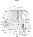
- a sixth aspect of the present invention further addresses the above-described problems by providing the thrust bearing for a vehicle according to the fifth aspect of the present invention, wherein the annular liquid inclusion body is mounted in an annular concave portion provided on a case top surface of the upper case, and a load receiving surface is formed at an upper end of the annular liquid inclusion body so as to upwardly project from the case top surface of the upper case, the load receiving surface being in contact with the vehicle body-side attaching portion for receiving a load.
- a sixteen aspect of the present invention further addresses the above-described problems by providing the thrust bearing for a vehicle according to any one of the first to fourteenth aspects of the present invention, wherein the load sensor is connected via a communication circuit to a load amount manager that manages a load amount of the vehicle by receiving an output signal from the load sensor, and the load amount manager manages the load amount of each vehicle online.
- a seventeenth aspect of the present invention further addresses the above-described problems by providing the thrust bearing for a vehicle according to any one of the first to fourteenth aspects of the present invention, wherein the load sensor is connected to a controller that controls at least either a damping force of the shock absorber or a spring rate of an air suspension by receiving an output signal from the load sensor, and the controller controls at least either the damping force or the spring rate in accordance with the amount of load vertically acting on the suspension.
- the film-type load sensor includes a film layer that deforms in accordance with the amount of the load vertically acting on the suspension, and an electric resistance of the film layer varies in accordance with the amount of deformation due to the load vertically acting on the suspension, the value of electric current flowing through the film layer varies in accordance with the amount of the load vertically acting on the suspension.
- the value of electric current flowing through the film layer varies in accordance with the amount of the load vertically acting on the suspension.
- the film layer is arranged on a bottom of a concave portion provided on a case top surface of the upper case, and a spacing member is provided on the film layer in the concave portion, at least a part of the spacing member on a top surface side thereof upwardly projecting from the case top surface of the upper case and being in contact with the vehicle body-side attaching portion, a load of the vehicle acts on the film layer by way of the spacing member with little interference from other members.
- the load sensor is connected to a controller that controls at least either a damping force of the shock absorber or a spring rate of an air suspension by receiving an output signal from the load sensor, and the controller controls at least either the damping force or the spring rate in accordance with the amount of load vertically acting on the suspension
- the damping force or the spring rate can be increased as the amount of the load increases, for example, for receiving the increase of the load.
- a spring pad SP made of rubber in an annular shape is provided on a lower case bottom surface 121e of the lower case base 121.
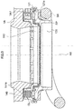
- the hydraulic load sensor 140 which is a hydraulic load sensor for measuring a movable load, or a load vertically acting on the strut-type suspension, is provided in the annular concavity 111aa of the upper case 110, for example.
- the hydraulic load sensor 140 may be provided in the lower case 120.
- the hydraulic load sensor 140 is connected via the connector 143 to the controller CT that actively controls a damping force of the shock absorber by receiving an output signal from the hydraulic load sensor 140 to monitor an input load from a tire (suspension).
- the thrust bearing 200 for a vehicle as the second embodiment of the present invention includes an upper case 210 made of synthetic resin, a lower case 220 made of synthetic resin, and a sliding bearing piece 230 as a bearing piece made of synthetic resin.
- the upper case 210 is configured to abut against a vehicle-side attaching member VA, or a vehicle body-side attaching portion.
- the upper case 210 is provided on the lower case 220 so that the lower case 220 is rotatable with respect to the upper case 210 about an axial center AX of the piston rod.
- the controller CT includes an arithmetic unit such as a CPU, and may be integrated with the film-type load sensor 240 at the interior of the upper case 210.
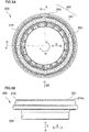
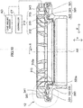
- Fig. 9(A) is a top view of the thrust bearing 300 for a vehicle as the third embodiment of the present invention.
- Fig. 9(B) is a side view as seen in a direction represented with reference numeral 9B in Fig. 9(A) .
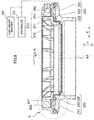
- Fig. 10 is a cross-sectional view as seen along line 10-10 illustrated in Fig. 9(A) .
- Fig. 11 is a cross-sectional view of the thrust bearing 300 for a vehicle as the third embodiment of the present invention incorporated into a strut-type suspension.
- Fig. 12 is an enlarged cross-sectional view of the portion represented with reference numeral 12 in Fig. 10 .
- the thrust bearing 300 for a vehicle as the third embodiment of the present invention includes an upper case 310 made of synthetic resin, a lower case 320 made of synthetic resin, and a sliding bearing piece 330 as a bearing piece made of synthetic resin.
- An inner annular engaging claw 321a is formed on a radial outer side of the lower case base 321.
- the inner annular engaging claw 321a engages with an outer annular engaging claw 313a formed on an outer circumference-side cylindrical portion 313 of the upper case 310 so as to be rotatable in a circumferential direction R.
- the thrust sliding bearing piece portion 331 includes a bearing top surface 331a that slidably contacts with the upper case bottom surface 311b of the upper case base 311, and a bearing bottom surface 331b that contacts with the lower case top surface 321c of the lower case base 321 of the lower case 320.
- the radial sliding bearing piece portion 332 includes a bearing inner circumferential surface 332a that slidably contacts with the outer circumferential surface 312b of the inner circumference-side cylindrical portion 312 of the upper case 310, and an outer circumferential surface 332b that contacts with the inner circumferential surface 321d of the lower case base 321 of the lower case 320.
- the light emitting part 342a is provided at one end in a circumferential direction of the light emitting/receiving portion 342 and is configured to emit light.
- the FBG (Fiber Bragg Granting) sensor is a sensor that is microfabricated within an optical fiber.
- the sensor includes a plurality of layers that have different refractive indices and work as diffraction gratings.
- the sensor reflects particular wavelengths of light and transmits all others for measuring a stress, distortion, pressure, or the like.
Landscapes
- Engineering & Computer Science (AREA)
- General Engineering & Computer Science (AREA)
- Mechanical Engineering (AREA)
- Physics & Mathematics (AREA)
- General Physics & Mathematics (AREA)
- Chemical & Material Sciences (AREA)
- Analytical Chemistry (AREA)
- Transportation (AREA)
- Vehicle Body Suspensions (AREA)
- Force Measurement Appropriate To Specific Purposes (AREA)
- Fluid-Damping Devices (AREA)
Claims (19)
- Axiallager (100; 200; 300) für ein Fahrzeug, umfassend: ein Obergehäuse (110; 210; 310), das an einem fahrzeugkarosserieseitigen Anbringungsteil (VA) anliegt; und ein Untergehäuse (120; 220; 320), auf dem das Obergehäuse (110; 210; 310) so vorgesehen ist, dass das Untergehäuse (120; 220; 320) bezüglich des Obergehäuses (110; 210; 310) um eine Mittelachse einer in einem Stoßdämpfer einer Aufhängung des Fahrzeugs benutzten Kolbenstange (AX) drehbar ist, dadurch gekennzeichnet, dass
das Axiallager (100; 200; 300) weiter einen Lastsensor (140; 240; 340) zum Messen einer Last umfasst, die vertikal auf die Aufhängung wirkt. - Axiallager (100; 200; 300) für ein Fahrzeug nach Anspruch 1, dadurch gekennzeichnet, dass ein ringförmiges Lagerteil (130; 230; 330) zum Aufnehmen einer auf das Axiallager (100; 200; 300) wirkenden Axiallast in einem ringförmigen Raum angeordnet ist, der zwischen dem Obergehäuse (110; 210; 310) und dem Untergehäuse (120; 220; 320) gebildet ist.
- Axiallager (100; 200; 300) für ein Fahrzeug nach Anspruch 2, dadurch gekennzeichnet, dass der Lastsensor (140; 240; 340) entweder im Obergehäuse (110; 210; 310), im Lagerteil (130; 230; 330) oder im Untergehäuse (120; 220; 320) vorgesehen ist.
- Axiallager (100; 200; 300) für ein Fahrzeug nach einem beliebigen der Ansprüche 1 bis 3, dadurch gekennzeichnet, dass der Lastsensor (140; 240; 340) ein hydraulischer Lastsensor (140) zum Messen der Last ist.
- Axiallager (100; 200; 300) für ein Fahrzeug nach Anspruch 4, dadurch gekennzeichnet, dassder hydraulische Lastsensor (140) enthält: ein ringförmiges Flüssigkeitseinschlusselement (141) zum Aufnehmen der vertikal auf die Aufhängung wirkenden Last; und einen Druck-/Signalwandler (142), verbunden mit dem ringförmigen Flüssigkeitseinschlusselement (141), zum Umwandeln des Drucks einer Flüssigkeit in dem ringförmigen Flüssigkeitseinschlusselement (141) in ein Signal, unddas ringförmige Flüssigkeitseinschlusselement (141) konzentrisch bezüglich einer Mittelachse des Axiallagers angeordnet ist.
- Axiallager (100; 200; 300) für ein Fahrzeug nach Anspruch 5, dadurch gekennzeichnet, dassdas ringförmige Flüssigkeitseinschlusselement (141) in einem ringförmigen konkaven Bereich (111aa; 211aa; 311aa) montiert ist, der auf einer oberen Gehäusefläche (111a; 211a; 311a) des Obergehäuses (110; 210; 310) vorgesehen ist, undeine Lastaufnahmefläche (141a) so an einem oberen Ende des ringförmigen Flüssigkeitseinschlusselements (141) ausgebildet ist, dass sie von der oberen Gehäusefläche (111a; 211a; 311a) des Obergehäuses (110; 210; 310) nach oben ragt, wobei die Lastaufnahmefläche (141a) zum Aufnehmen einer Last mit dem fahrzeugkarosserieseitigen Anbringungsteil (VA) in Kontakt steht.
- Axiallager (100; 200; 300) für ein Fahrzeug nach einem beliebigen der Ansprüche 1 bis 3, dadurch gekennzeichnet, dass der Lastsensor (140; 240; 340) ein Folien-Lastsensor (240) zum Messen der Last ist.
- Axiallager (100; 200; 300) für ein Fahrzeug nach Anspruch 7, dadurch gekennzeichnet, dassder Folien-Lastsensor (240) eine Folienschicht (241) enthält, die sich gemäß dem Betrag der vertikal auf die Aufhängung wirkenden Last verformt, undsich ein elektrischer Widerstand der Folienschicht (241) gemäß dem Betrag der Verformung aufgrund der vertikal auf die Aufhängung wirkenden Last ändert.
- Axiallager (100; 200; 300) für ein Fahrzeug nach Anspruch 8, dadurch gekennzeichnet, dassdie Folienschicht (241) auf einem Boden eines konkaven Bereichs (111aa; 211aa; 311aa) angeordnet ist, der auf einer oberen Gehäusefläche (111a; 211a; 311a) des Obergehäuses (110; 210; 310) vorgesehen ist, undein Abstandselement (250) auf der Folienschicht (241) in dem konkaven Bereich (111aa; 211aa; 311aa) vorgesehen ist, wobei zumindest ein Teil des Abstandselements (250) auf einer Seite dessen oberer Fläche (251) von der oberen Gehäusefläche (111a; 211a; 311a) des Obergehäuses (110; 210; 310) nach oben ragt und mit dem fahrzeugkarosserieseitigen Anbringungsteil (VA) in Kontakt steht.
- Axiallager (100; 200; 300) für ein Fahrzeug nach Anspruch 8 oder 9, dadurch gekennzeichnet, dasseine Vielzahl von Folienschichten (241) in einer umlaufenden Richtung (R) der Kolbenstange angeordnet ist, undder gesamte elektrische Widerstand der Vielzahl von Folienschichten (241) als Wert der vertikal auf die Aufhängung wirkenden Last benutzt wird.
- Axiallager (100; 200; 300) für ein Fahrzeug nach einem beliebigen der Ansprüche 1 bis 3, dadurch gekennzeichnet, dass der Lastsensor (140; 240; 340) ein Lichtleitfaser-Lastsensor (340) zum Messen der Last ist.
- Axiallager (100; 200; 300) für ein Fahrzeug nach Anspruch 11, dadurch gekennzeichnet, dassder Lichtleitfaser-Lastsensor (340) enthält: einen Lichtsendeteil (342), der Licht aussendet; eine Lichtleitfaser (341), die das Licht von Lichtsendeteil (342) leitet und sich gemäß dem Betrag der vertikal auf die Aufhängung wirkenden Last verformt; und einen Lichtempfangsteil (342), der das durch die Lichtleitfaser (341) fortgepflanzte Licht empfängt und eine Phase des Lichts misst, undsich eine Phase der durch die Lichtleitfaser (341) fortgepflanzten Wellenform gemäß dem Betrag der Verformung der Lichtleitfaser (341) aufgrund der vertikal auf die Aufhängung wirkenden Last ändert.
- Axiallager (100; 200; 300) für ein Fahrzeug nach Anspruch 12, dadurch gekennzeichnet, dassdie Lichtleitfaser (341) auf einem Boden eines konkaven Bereichs (111aa; 211aa; 311aa) angeordnet ist, der auf einer oberen Gehäusefläche (111a; 211a; 311a) des Obergehäuses (110; 210; 310) vorgesehen ist, undein Abstandselement (350) auf der Lichtleitfaser (341) in dem konkaven Bereich (111aa; 211aa; 311aa) vorgesehen ist, wobei zumindest ein Teil des Abstandselements (350) auf einer Seite dessen oberer Fläche (351) von der oberen Gehäusefläche (111a; 211a; 311a) des Obergehäuses (110; 210; 310) nach oben ragt und mit dem fahrzeugkarosserieseitigen Anbringungsteil (VA) in Kontakt steht.
- Axiallager (100; 200; 300) für ein Fahrzeug nach einem beliebigen der Ansprüche 1 bis 13, dadurch gekennzeichnet, dass die Aufhängung eine Federbeinaufhängung ist.
- Axiallager (100; 200; 300) für ein Fahrzeug nach einem beliebigen der Ansprüche 1 bis 14, dadurch gekennzeichnet, dassder Lastsensor (140; 240; 340) mit einer Steuerung (CT) verbunden ist, die eine Bremse des Fahrzeugs durch ein Empfangen eines Ausgangssignals vom Lastsensor (140; 240; 340) steuert, unddie Steuerung (CT) eine Bremskraft der Bremse gemäß dem Betrag der vertikal auf die Aufhängung wirkenden Last steuert, wenn ein Fahrer des Fahrzeugs die Bremse betätigt.
- Axiallager (100; 200; 300) für ein Fahrzeug nach einem beliebigen der Ansprüche 1 bis 14, dadurch gekennzeichnet, dassder Lastsensor (140; 240; 340) über einen Kommunikationskreis mit einer Lastbetragsverwaltungseinheit (AD) verbunden ist, die einen Lastbetrag des Fahrzeugs durch ein Empfangen eines Ausgangssignals vom Lastsensor (140; 240; 340) verwaltet, unddie Lastbetragsverwaltungseinheit (AD) den Lastbetrag jedes Fahrzeugs online verwaltet.
- Axiallager (100; 200; 300) für ein Fahrzeug nach einem beliebigen der Ansprüche 1 bis 14, dadurch gekennzeichnet, dassder Lastsensor (140; 240; 340) mit einer Steuerung (CT) verbunden ist, die mindestens entweder eine Dämpfungskraft des Stoßdämpfers oder eine Federrate einer Luftfederung durch ein Empfangen eines Ausgangssignals vom Lastsensor (140; 240; 340) steuert, unddie Steuerung (CT) mindestens entweder die Dämpfungskraft oder die Federrate gemäß dem Betrag der vertikal auf die Aufhängung wirkenden Last steuert.
- Axiallager (100; 200; 300) für ein Fahrzeug nach einem beliebigen der Ansprüche 1 bis 14, dadurch gekennzeichnet, dassder Lastsensor (140; 240; 340) mit einer Steuerung (CT) verbunden ist, die mindestens entweder eine Dämpfungskraft des Stoßdämpfers oder eine Federrate einer Luftfederung durch ein Empfangen eines Ausgangssignals vom Lastsensor (140; 240; 340) steuert, um den Längs- und den Seitenausgleich des Fahrzeugs zu überwachen, unddie Steuerung (CT) mindestens entweder die Dämpfungskraft des Stoßdämpfers oder die Federrate gemäß den Längs- und Seitenunterschieden zwischen den Beträgen einer vertikal wirkenden Last steuert, die durch jede Aufhängung des Fahrzeugs gemessen wird, sodass die Neigung des Fahrzeugs reduziert wird.
- Axiallager (100; 200; 300) für ein Fahrzeug nach einem beliebigen der Ansprüche 1 bis 14, dadurch gekennzeichnet, dass
der Lastsensor (140; 240; 340) mit einer Steuerung (CT) verbunden ist, die eine Dämpfungskraft des Stoßdämpfers durch ein Empfangen eines Ausgangssignals vom Lastsensor (140; 240; 340) aktiv steuert, um eine eingegebene Last von einem Reifen zu überwachen.
Applications Claiming Priority (2)
| Application Number | Priority Date | Filing Date | Title |
|---|---|---|---|
| JP2014198896A JP6606321B2 (ja) | 2014-09-29 | 2014-09-29 | 車両用スラスト軸受 |
| PCT/JP2015/075545 WO2016052106A1 (ja) | 2014-09-29 | 2015-09-09 | 車両用スラスト軸受 |
Publications (3)
| Publication Number | Publication Date |
|---|---|
| EP3203100A1 EP3203100A1 (de) | 2017-08-09 |
| EP3203100A4 EP3203100A4 (de) | 2018-05-23 |
| EP3203100B1 true EP3203100B1 (de) | 2020-11-04 |
Family
ID=55630149
Family Applications (1)
| Application Number | Title | Priority Date | Filing Date |
|---|---|---|---|
| EP15846137.6A Active EP3203100B1 (de) | 2014-09-29 | 2015-09-09 | Axiallager für ein fahrzeug |
Country Status (7)
| Country | Link |
|---|---|
| US (1) | US10508689B2 (de) |
| EP (1) | EP3203100B1 (de) |
| JP (1) | JP6606321B2 (de) |
| KR (1) | KR102423035B1 (de) |
| CN (1) | CN106687704B (de) |
| BR (1) | BR112017002086B1 (de) |
| WO (1) | WO2016052106A1 (de) |
Families Citing this family (17)
| Publication number | Priority date | Publication date | Assignee | Title |
|---|---|---|---|---|
| JP2017227634A (ja) | 2016-06-17 | 2017-12-28 | 日本精工株式会社 | 車両の重量測定装置 |
| JP2018009980A (ja) * | 2016-06-29 | 2018-01-18 | 日本精工株式会社 | 車両の重量測定装置 |
| JPWO2018016481A1 (ja) * | 2016-07-19 | 2019-05-09 | 日本精工株式会社 | 車両の重量測定装置 |
| DE102017117081A1 (de) * | 2017-07-28 | 2019-01-31 | Schaeffler Technologies AG & Co. KG | Federbeinlager |
| JP2019027958A (ja) * | 2017-07-31 | 2019-02-21 | オイレス工業株式会社 | ロードセルおよび軸受 |
| CN107677397A (zh) * | 2017-08-14 | 2018-02-09 | 上海交通大学 | 一种轴承负荷在线测量方法及系统 |
| US20200182324A1 (en) * | 2017-11-24 | 2020-06-11 | Nsk Ltd. | Vehicle weight measurement device |
| JP6917290B2 (ja) * | 2017-12-12 | 2021-08-11 | オイレス工業株式会社 | 滑り軸受 |
| CN111630283A (zh) * | 2018-01-10 | 2020-09-04 | 奥依列斯工业株式会社 | 滑动轴承 |
| US10801549B2 (en) * | 2018-05-31 | 2020-10-13 | General Electric Company | Axial load management system |
| CN111853071B (zh) * | 2019-04-11 | 2024-09-03 | 斯凯孚公司 | 一种滚子轴承、风力涡轮机和风力涡轮机的控制方法 |
| DE102019214488A1 (de) * | 2019-09-23 | 2021-03-25 | Aktiebolaget Skf | Lager mit einer einzelnen optischen Messfaser zur Lasterfassung und Lagereinheit mit kombinierten Lagern |
| CN111043157B (zh) * | 2019-12-30 | 2022-10-11 | 浙江吉利控股集团有限公司 | 一种轴承、前滑柱总成及汽车 |
| GB2593711A (en) * | 2020-03-30 | 2021-10-06 | Airbus Operations Ltd | Sensor assembly |
| CN111810527A (zh) * | 2020-07-16 | 2020-10-23 | 苏州轴承厂股份有限公司 | 一种高速高同心度的组合型滚针轴承组件 |
| CN114738383A (zh) * | 2021-01-07 | 2022-07-12 | 易格斯(上海)拖链系统有限公司 | 塑料滑动轴承 |
| EP4538056B1 (de) * | 2023-10-12 | 2026-04-22 | Venturi Lab SA | Verformbares rad mit nicht-pneumatischer laufstreifen und mit laufflächenheizung für bedingungen auf dem mond und mars |
Family Cites Families (29)
| Publication number | Priority date | Publication date | Assignee | Title |
|---|---|---|---|---|
| JP2857422B2 (ja) * | 1989-08-02 | 1999-02-17 | 株式会社ユニシアジェックス | 減衰力可変型サスペンションユニット |
| JPH0443088U (de) * | 1990-08-15 | 1992-04-13 | ||
| US5072611A (en) * | 1990-09-04 | 1991-12-17 | The B. F. Goodrich Company | Apparatus and method for testing wheels, bearings and lubricants |
| US5269383A (en) * | 1992-01-15 | 1993-12-14 | Drilex Systems, Inc. | Navigable downhole drilling system |
| JPH08132840A (ja) * | 1994-11-02 | 1996-05-28 | Toyota Motor Corp | 車輌の車高調整装置 |
| JPH0961268A (ja) * | 1995-08-25 | 1997-03-07 | Nippon Seiko Kk | 軸受用荷重測定装置 |
| JPH09142123A (ja) * | 1995-11-27 | 1997-06-03 | Toyota Motor Corp | 車両用サスペンション装置 |
| USRE39838E1 (en) * | 2000-04-10 | 2007-09-18 | The Timken Company | Bearing assembly with sensors for monitoring loads |
| JP2004034865A (ja) * | 2002-07-04 | 2004-02-05 | Hitachi Plant Eng & Constr Co Ltd | 重量物搬送台車用サスペンション装置 |
| FR2847515B1 (fr) * | 2002-11-27 | 2006-07-14 | Roulements Soc Nouvelle | Butee de suspension instrumentee en deformation pour mesurer les efforts |
| FR2847516B1 (fr) | 2002-11-27 | 2005-01-28 | Roulements Soc Nouvelle | Butee de suspension instrumentee en rotation pour mesurer les efforts verticaux |
| JP2005090525A (ja) * | 2003-09-12 | 2005-04-07 | Mitsui Miike Mach Co Ltd | 遊星減速機 |
| JP4391406B2 (ja) * | 2004-12-17 | 2009-12-24 | Ntn株式会社 | スラスト軸受 |
| CA2631435C (en) * | 2005-12-20 | 2014-08-12 | Antares Pharma, Inc. | Needle-free injection device |
| US20080142102A1 (en) * | 2006-12-18 | 2008-06-19 | Savard Raymond T | Check Valve and Pump for High Purity Fluid Handling Systems |
| JP2009216664A (ja) * | 2008-03-12 | 2009-09-24 | Railway Technical Res Inst | 内輪へのひずみセンサ内蔵型転がり軸受の荷重分布測定方法及びその装置 |
| JP5265947B2 (ja) * | 2008-03-13 | 2013-08-14 | 株式会社ユニバンス | 四輪駆動車用駆動力伝達装置 |
| MX2010013178A (es) * | 2008-06-05 | 2011-04-21 | Mazaro Nv | Transmision variable reversible. |
| US8550863B1 (en) * | 2008-09-24 | 2013-10-08 | James P. von Wolske | Watercraft propeller propulsion system having a gimbal assembly with an external gimbal ring |
| JP5272626B2 (ja) * | 2008-09-30 | 2013-08-28 | 三菱自動車工業株式会社 | ストロークセンサ |
| DE102009060999A1 (de) * | 2009-06-24 | 2011-01-05 | German Gresser | Energieoptimiertes Elektrofahrzeug mit autarker Stromversorgung und Verfahren zur Stromerzeugung, bevorzugt aus kinetischer und Gravitationsenergie |
| US20110076387A1 (en) * | 2009-09-29 | 2011-03-31 | Lonza, Inc. | Method for imparting antibiotic activity to the surface of a solid substrate |
| JP2011079421A (ja) * | 2009-10-07 | 2011-04-21 | Univance Corp | 4輪駆動車用駆動力伝達装置 |
| US9404540B2 (en) * | 2011-09-29 | 2016-08-02 | Ntn Corporation | Wheel bearing apparatus with sensor |
| JP5908243B2 (ja) * | 2011-09-29 | 2016-04-26 | Ntn株式会社 | センサ付車輪用軸受装置 |
| JP5741964B2 (ja) * | 2012-12-19 | 2015-07-01 | カシオ計算機株式会社 | センサデータ抽出システム、センサデータ抽出方法およびセンサデータ抽出プログラム |
| GB201223469D0 (en) * | 2012-12-27 | 2013-02-13 | Mazaro Nv | Design features to improve power density and efficiency of a reversible variable transmission - RVT |
| JP6029576B2 (ja) * | 2013-12-20 | 2016-11-24 | 株式会社神戸製鋼所 | 密閉式混練装置のロータに加わるスラスト荷重の計測装置 |
| JP6303239B2 (ja) * | 2014-08-12 | 2018-04-04 | オイレス工業株式会社 | スラスト滑り軸受 |
-
2014
- 2014-09-29 JP JP2014198896A patent/JP6606321B2/ja active Active
-
2015
- 2015-09-09 WO PCT/JP2015/075545 patent/WO2016052106A1/ja not_active Ceased
- 2015-09-09 EP EP15846137.6A patent/EP3203100B1/de active Active
- 2015-09-09 KR KR1020177002046A patent/KR102423035B1/ko active Active
- 2015-09-09 CN CN201580048254.3A patent/CN106687704B/zh active Active
- 2015-09-09 US US15/503,420 patent/US10508689B2/en active Active
- 2015-09-09 BR BR112017002086-6A patent/BR112017002086B1/pt active IP Right Grant
Non-Patent Citations (1)
| Title |
|---|
| None * |
Also Published As
| Publication number | Publication date |
|---|---|
| JP2016068706A (ja) | 2016-05-09 |
| JP6606321B2 (ja) | 2019-11-13 |
| KR20170065485A (ko) | 2017-06-13 |
| CN106687704A (zh) | 2017-05-17 |
| KR102423035B1 (ko) | 2022-07-21 |
| EP3203100A4 (de) | 2018-05-23 |
| BR112017002086B1 (pt) | 2022-04-05 |
| EP3203100A1 (de) | 2017-08-09 |
| BR112017002086A2 (pt) | 2017-12-19 |
| CN106687704B (zh) | 2019-04-26 |
| WO2016052106A1 (ja) | 2016-04-07 |
| US10508689B2 (en) | 2019-12-17 |
| US20170227057A1 (en) | 2017-08-10 |
Similar Documents
| Publication | Publication Date | Title |
|---|---|---|
| EP3203100B1 (de) | Axiallager für ein fahrzeug | |
| JP6563010B2 (ja) | 改善された触覚レンダリングを有する触覚インタフェース | |
| US5859692A (en) | Height sensor and air spring apparatus incorporating the same in the air chamber | |
| JP2019523375A (ja) | ブレーキパッド摩耗センサ | |
| JP2017530473A (ja) | 触覚感覚の制御を改善した触覚インタフェース | |
| EP1565362A2 (de) | Achseinheit mit schlupfsensor und schlupfmessverfahren | |
| EP0942839A1 (de) | System und verfahren zur detektion von fahrzeugüberrollzuständen | |
| KR20080022138A (ko) | 센서 장치를 포함하는 볼-앤드-소켓 조인트, 부하를측정하기 위한 방법, 그리고 마모를 측정하기 위한 방법 | |
| EP3133381A1 (de) | Mit einem lastsensor ausgestattete lagervorrichtung | |
| US20150053487A1 (en) | Vehicle weight sensor | |
| Shams et al. | Compact and lightweight optical torque sensor for robots with increased range | |
| KR101769295B1 (ko) | 차량 중량 측정 장치를 통해 측정된 차량 중량의 모니터링 시스템 | |
| EP4431307A1 (de) | Reifenanordnung und reifenkraftschätzsystem | |
| CN113984165A (zh) | 一种应用于车辆的称重压力传感器 | |
| KR101917553B1 (ko) | 모의 코일 스프링 장치와 그 제어 방법 | |
| CN210243076U (zh) | 一种六分力传感器垂向力及侧向纵向扭矩标定装置 | |
| CN210618104U (zh) | 一种支腿式工程机械 | |
| US20100300190A1 (en) | Monocoque of vehicle capable of detecting strain | |
| US10001420B2 (en) | Instrumented spindle or load cell for high load, high resolution | |
| CN108438128B (zh) | 交通工具及其控制方法、控制装置及存储介质 | |
| JP2009504483A (ja) | 荷重感知車輪サポートナックル組立及び使用方法 | |
| CN115183928B (zh) | 车轮支反力检测装置、系统及高空作业平台 | |
| CN120141561B (zh) | 一种基于轮腿机器人的足端触地信息检测方法、装置、设备及介质 | |
| Wang | Study on multifunctional sensors for trucks safety monitoring | |
| JP2005083783A (ja) | 動摩擦係数測定装置 |
Legal Events
| Date | Code | Title | Description |
|---|---|---|---|
| STAA | Information on the status of an ep patent application or granted ep patent |
Free format text: STATUS: THE INTERNATIONAL PUBLICATION HAS BEEN MADE |
|
| PUAI | Public reference made under article 153(3) epc to a published international application that has entered the european phase |
Free format text: ORIGINAL CODE: 0009012 |
|
| STAA | Information on the status of an ep patent application or granted ep patent |
Free format text: STATUS: REQUEST FOR EXAMINATION WAS MADE |
|
| 17P | Request for examination filed |
Effective date: 20170407 |
|
| AK | Designated contracting states |
Kind code of ref document: A1 Designated state(s): AL AT BE BG CH CY CZ DE DK EE ES FI FR GB GR HR HU IE IS IT LI LT LU LV MC MK MT NL NO PL PT RO RS SE SI SK SM TR |
|
| AX | Request for extension of the european patent |
Extension state: BA ME |
|
| DAV | Request for validation of the european patent (deleted) | ||
| DAX | Request for extension of the european patent (deleted) | ||
| A4 | Supplementary search report drawn up and despatched |
Effective date: 20180419 |
|
| RIC1 | Information provided on ipc code assigned before grant |
Ipc: F16C 17/04 20060101ALI20180413BHEP Ipc: B60G 15/06 20060101ALI20180413BHEP Ipc: F16C 17/24 20060101ALI20180413BHEP Ipc: F16C 19/10 20060101ALI20180413BHEP Ipc: G01L 5/00 20060101ALI20180413BHEP Ipc: F16C 41/00 20060101AFI20180413BHEP Ipc: F16F 9/54 20060101ALI20180413BHEP Ipc: B60G 17/019 20060101ALI20180413BHEP Ipc: F16C 19/52 20060101ALI20180413BHEP |
|
| GRAP | Despatch of communication of intention to grant a patent |
Free format text: ORIGINAL CODE: EPIDOSNIGR1 |
|
| STAA | Information on the status of an ep patent application or granted ep patent |
Free format text: STATUS: GRANT OF PATENT IS INTENDED |
|
| INTG | Intention to grant announced |
Effective date: 20200415 |
|
| GRAS | Grant fee paid |
Free format text: ORIGINAL CODE: EPIDOSNIGR3 |
|
| GRAA | (expected) grant |
Free format text: ORIGINAL CODE: 0009210 |
|
| STAA | Information on the status of an ep patent application or granted ep patent |
Free format text: STATUS: THE PATENT HAS BEEN GRANTED |
|
| AK | Designated contracting states |
Kind code of ref document: B1 Designated state(s): AL AT BE BG CH CY CZ DE DK EE ES FI FR GB GR HR HU IE IS IT LI LT LU LV MC MK MT NL NO PL PT RO RS SE SI SK SM TR |
|
| REG | Reference to a national code |
Ref country code: GB Ref legal event code: FG4D |
|
| REG | Reference to a national code |
Ref country code: CH Ref legal event code: EP |
|
| REG | Reference to a national code |
Ref country code: AT Ref legal event code: REF Ref document number: 1331207 Country of ref document: AT Kind code of ref document: T Effective date: 20201115 |
|
| REG | Reference to a national code |
Ref country code: IE Ref legal event code: FG4D |
|
| REG | Reference to a national code |
Ref country code: DE Ref legal event code: R096 Ref document number: 602015061652 Country of ref document: DE |
|
| REG | Reference to a national code |
Ref country code: NL Ref legal event code: MP Effective date: 20201104 |
|
| REG | Reference to a national code |
Ref country code: AT Ref legal event code: MK05 Ref document number: 1331207 Country of ref document: AT Kind code of ref document: T Effective date: 20201104 |
|
| PG25 | Lapsed in a contracting state [announced via postgrant information from national office to epo] |
Ref country code: NO Free format text: LAPSE BECAUSE OF FAILURE TO SUBMIT A TRANSLATION OF THE DESCRIPTION OR TO PAY THE FEE WITHIN THE PRESCRIBED TIME-LIMIT Effective date: 20210204 Ref country code: PT Free format text: LAPSE BECAUSE OF FAILURE TO SUBMIT A TRANSLATION OF THE DESCRIPTION OR TO PAY THE FEE WITHIN THE PRESCRIBED TIME-LIMIT Effective date: 20210304 Ref country code: RS Free format text: LAPSE BECAUSE OF FAILURE TO SUBMIT A TRANSLATION OF THE DESCRIPTION OR TO PAY THE FEE WITHIN THE PRESCRIBED TIME-LIMIT Effective date: 20201104 Ref country code: FI Free format text: LAPSE BECAUSE OF FAILURE TO SUBMIT A TRANSLATION OF THE DESCRIPTION OR TO PAY THE FEE WITHIN THE PRESCRIBED TIME-LIMIT Effective date: 20201104 Ref country code: GR Free format text: LAPSE BECAUSE OF FAILURE TO SUBMIT A TRANSLATION OF THE DESCRIPTION OR TO PAY THE FEE WITHIN THE PRESCRIBED TIME-LIMIT Effective date: 20210205 |
|
| PG25 | Lapsed in a contracting state [announced via postgrant information from national office to epo] |
Ref country code: IS Free format text: LAPSE BECAUSE OF FAILURE TO SUBMIT A TRANSLATION OF THE DESCRIPTION OR TO PAY THE FEE WITHIN THE PRESCRIBED TIME-LIMIT Effective date: 20210304 Ref country code: PL Free format text: LAPSE BECAUSE OF FAILURE TO SUBMIT A TRANSLATION OF THE DESCRIPTION OR TO PAY THE FEE WITHIN THE PRESCRIBED TIME-LIMIT Effective date: 20201104 Ref country code: SE Free format text: LAPSE BECAUSE OF FAILURE TO SUBMIT A TRANSLATION OF THE DESCRIPTION OR TO PAY THE FEE WITHIN THE PRESCRIBED TIME-LIMIT Effective date: 20201104 Ref country code: LV Free format text: LAPSE BECAUSE OF FAILURE TO SUBMIT A TRANSLATION OF THE DESCRIPTION OR TO PAY THE FEE WITHIN THE PRESCRIBED TIME-LIMIT Effective date: 20201104 Ref country code: BG Free format text: LAPSE BECAUSE OF FAILURE TO SUBMIT A TRANSLATION OF THE DESCRIPTION OR TO PAY THE FEE WITHIN THE PRESCRIBED TIME-LIMIT Effective date: 20210204 Ref country code: ES Free format text: LAPSE BECAUSE OF FAILURE TO SUBMIT A TRANSLATION OF THE DESCRIPTION OR TO PAY THE FEE WITHIN THE PRESCRIBED TIME-LIMIT Effective date: 20201104 Ref country code: AT Free format text: LAPSE BECAUSE OF FAILURE TO SUBMIT A TRANSLATION OF THE DESCRIPTION OR TO PAY THE FEE WITHIN THE PRESCRIBED TIME-LIMIT Effective date: 20201104 |
|
| REG | Reference to a national code |
Ref country code: LT Ref legal event code: MG9D |
|
| PG25 | Lapsed in a contracting state [announced via postgrant information from national office to epo] |
Ref country code: HR Free format text: LAPSE BECAUSE OF FAILURE TO SUBMIT A TRANSLATION OF THE DESCRIPTION OR TO PAY THE FEE WITHIN THE PRESCRIBED TIME-LIMIT Effective date: 20201104 |
|
| PG25 | Lapsed in a contracting state [announced via postgrant information from national office to epo] |
Ref country code: CZ Free format text: LAPSE BECAUSE OF FAILURE TO SUBMIT A TRANSLATION OF THE DESCRIPTION OR TO PAY THE FEE WITHIN THE PRESCRIBED TIME-LIMIT Effective date: 20201104 Ref country code: EE Free format text: LAPSE BECAUSE OF FAILURE TO SUBMIT A TRANSLATION OF THE DESCRIPTION OR TO PAY THE FEE WITHIN THE PRESCRIBED TIME-LIMIT Effective date: 20201104 Ref country code: SM Free format text: LAPSE BECAUSE OF FAILURE TO SUBMIT A TRANSLATION OF THE DESCRIPTION OR TO PAY THE FEE WITHIN THE PRESCRIBED TIME-LIMIT Effective date: 20201104 Ref country code: LT Free format text: LAPSE BECAUSE OF FAILURE TO SUBMIT A TRANSLATION OF THE DESCRIPTION OR TO PAY THE FEE WITHIN THE PRESCRIBED TIME-LIMIT Effective date: 20201104 Ref country code: RO Free format text: LAPSE BECAUSE OF FAILURE TO SUBMIT A TRANSLATION OF THE DESCRIPTION OR TO PAY THE FEE WITHIN THE PRESCRIBED TIME-LIMIT Effective date: 20201104 Ref country code: SK Free format text: LAPSE BECAUSE OF FAILURE TO SUBMIT A TRANSLATION OF THE DESCRIPTION OR TO PAY THE FEE WITHIN THE PRESCRIBED TIME-LIMIT Effective date: 20201104 |
|
| REG | Reference to a national code |
Ref country code: DE Ref legal event code: R097 Ref document number: 602015061652 Country of ref document: DE |
|
| PG25 | Lapsed in a contracting state [announced via postgrant information from national office to epo] |
Ref country code: DK Free format text: LAPSE BECAUSE OF FAILURE TO SUBMIT A TRANSLATION OF THE DESCRIPTION OR TO PAY THE FEE WITHIN THE PRESCRIBED TIME-LIMIT Effective date: 20201104 |
|
| PLBE | No opposition filed within time limit |
Free format text: ORIGINAL CODE: 0009261 |
|
| STAA | Information on the status of an ep patent application or granted ep patent |
Free format text: STATUS: NO OPPOSITION FILED WITHIN TIME LIMIT |
|
| 26N | No opposition filed |
Effective date: 20210805 |
|
| PG25 | Lapsed in a contracting state [announced via postgrant information from national office to epo] |
Ref country code: NL Free format text: LAPSE BECAUSE OF FAILURE TO SUBMIT A TRANSLATION OF THE DESCRIPTION OR TO PAY THE FEE WITHIN THE PRESCRIBED TIME-LIMIT Effective date: 20201104 Ref country code: IT Free format text: LAPSE BECAUSE OF FAILURE TO SUBMIT A TRANSLATION OF THE DESCRIPTION OR TO PAY THE FEE WITHIN THE PRESCRIBED TIME-LIMIT Effective date: 20201104 Ref country code: AL Free format text: LAPSE BECAUSE OF FAILURE TO SUBMIT A TRANSLATION OF THE DESCRIPTION OR TO PAY THE FEE WITHIN THE PRESCRIBED TIME-LIMIT Effective date: 20201104 |
|
| PG25 | Lapsed in a contracting state [announced via postgrant information from national office to epo] |
Ref country code: SI Free format text: LAPSE BECAUSE OF FAILURE TO SUBMIT A TRANSLATION OF THE DESCRIPTION OR TO PAY THE FEE WITHIN THE PRESCRIBED TIME-LIMIT Effective date: 20201104 |
|
| REG | Reference to a national code |
Ref country code: CH Ref legal event code: PL |
|
| REG | Reference to a national code |
Ref country code: BE Ref legal event code: MM Effective date: 20210930 |
|
| GBPC | Gb: european patent ceased through non-payment of renewal fee |
Effective date: 20210909 |
|
| PG25 | Lapsed in a contracting state [announced via postgrant information from national office to epo] |
Ref country code: IS Free format text: LAPSE BECAUSE OF FAILURE TO SUBMIT A TRANSLATION OF THE DESCRIPTION OR TO PAY THE FEE WITHIN THE PRESCRIBED TIME-LIMIT Effective date: 20210304 Ref country code: MC Free format text: LAPSE BECAUSE OF FAILURE TO SUBMIT A TRANSLATION OF THE DESCRIPTION OR TO PAY THE FEE WITHIN THE PRESCRIBED TIME-LIMIT Effective date: 20201104 |
|
| PG25 | Lapsed in a contracting state [announced via postgrant information from national office to epo] |
Ref country code: LU Free format text: LAPSE BECAUSE OF NON-PAYMENT OF DUE FEES Effective date: 20210909 Ref country code: IE Free format text: LAPSE BECAUSE OF NON-PAYMENT OF DUE FEES Effective date: 20210909 Ref country code: GB Free format text: LAPSE BECAUSE OF NON-PAYMENT OF DUE FEES Effective date: 20210909 Ref country code: FR Free format text: LAPSE BECAUSE OF NON-PAYMENT OF DUE FEES Effective date: 20210930 Ref country code: BE Free format text: LAPSE BECAUSE OF NON-PAYMENT OF DUE FEES Effective date: 20210930 |
|
| PG25 | Lapsed in a contracting state [announced via postgrant information from national office to epo] |
Ref country code: LI Free format text: LAPSE BECAUSE OF NON-PAYMENT OF DUE FEES Effective date: 20210930 Ref country code: CH Free format text: LAPSE BECAUSE OF NON-PAYMENT OF DUE FEES Effective date: 20210930 |
|
| PG25 | Lapsed in a contracting state [announced via postgrant information from national office to epo] |
Ref country code: HU Free format text: LAPSE BECAUSE OF FAILURE TO SUBMIT A TRANSLATION OF THE DESCRIPTION OR TO PAY THE FEE WITHIN THE PRESCRIBED TIME-LIMIT; INVALID AB INITIO Effective date: 20150909 |
|
| PG25 | Lapsed in a contracting state [announced via postgrant information from national office to epo] |
Ref country code: CY Free format text: LAPSE BECAUSE OF FAILURE TO SUBMIT A TRANSLATION OF THE DESCRIPTION OR TO PAY THE FEE WITHIN THE PRESCRIBED TIME-LIMIT Effective date: 20201104 |
|
| PG25 | Lapsed in a contracting state [announced via postgrant information from national office to epo] |
Ref country code: MK Free format text: LAPSE BECAUSE OF FAILURE TO SUBMIT A TRANSLATION OF THE DESCRIPTION OR TO PAY THE FEE WITHIN THE PRESCRIBED TIME-LIMIT Effective date: 20201104 |
|
| PG25 | Lapsed in a contracting state [announced via postgrant information from national office to epo] |
Ref country code: TR Free format text: LAPSE BECAUSE OF FAILURE TO SUBMIT A TRANSLATION OF THE DESCRIPTION OR TO PAY THE FEE WITHIN THE PRESCRIBED TIME-LIMIT Effective date: 20201104 |
|
| PG25 | Lapsed in a contracting state [announced via postgrant information from national office to epo] |
Ref country code: MT Free format text: LAPSE BECAUSE OF FAILURE TO SUBMIT A TRANSLATION OF THE DESCRIPTION OR TO PAY THE FEE WITHIN THE PRESCRIBED TIME-LIMIT Effective date: 20201104 |
|
| PGFP | Annual fee paid to national office [announced via postgrant information from national office to epo] |
Ref country code: DE Payment date: 20250730 Year of fee payment: 11 |