EP3203488A1 - Magnetkernkomponente und chipinduktor - Google Patents
Magnetkernkomponente und chipinduktor Download PDFInfo
- Publication number
- EP3203488A1 EP3203488A1 EP15845926.3A EP15845926A EP3203488A1 EP 3203488 A1 EP3203488 A1 EP 3203488A1 EP 15845926 A EP15845926 A EP 15845926A EP 3203488 A1 EP3203488 A1 EP 3203488A1
- Authority
- EP
- European Patent Office
- Prior art keywords
- core component
- magnetic core
- shaft portion
- winding shaft
- winding
- Prior art date
- Legal status (The legal status is an assumption and is not a legal conclusion. Google has not performed a legal analysis and makes no representation as to the accuracy of the status listed.)
- Withdrawn
Links
- 239000008358 core component Substances 0.000 title claims abstract description 58
- 238000004804 winding Methods 0.000 claims abstract description 74
- 238000005304 joining Methods 0.000 claims abstract description 30
- 239000000696 magnetic material Substances 0.000 claims description 16
- 230000000295 complement effect Effects 0.000 claims description 6
- 230000006835 compression Effects 0.000 claims description 5
- 238000007906 compression Methods 0.000 claims description 5
- 230000004907 flux Effects 0.000 abstract description 12
- 238000000465 moulding Methods 0.000 abstract description 6
- 239000000843 powder Substances 0.000 description 18
- 239000000463 material Substances 0.000 description 9
- 229910000859 α-Fe Inorganic materials 0.000 description 8
- 229910045601 alloy Inorganic materials 0.000 description 6
- 239000000956 alloy Substances 0.000 description 6
- 239000002994 raw material Substances 0.000 description 6
- 239000000758 substrate Substances 0.000 description 6
- XEEYBQQBJWHFJM-UHFFFAOYSA-N Iron Chemical compound [Fe] XEEYBQQBJWHFJM-UHFFFAOYSA-N 0.000 description 5
- 239000002245 particle Substances 0.000 description 5
- 238000000576 coating method Methods 0.000 description 4
- 239000011248 coating agent Substances 0.000 description 3
- 238000004519 manufacturing process Methods 0.000 description 3
- 238000000034 method Methods 0.000 description 3
- 229920005989 resin Polymers 0.000 description 3
- 239000011347 resin Substances 0.000 description 3
- 229910000702 sendust Inorganic materials 0.000 description 3
- 230000003746 surface roughness Effects 0.000 description 3
- RYGMFSIKBFXOCR-UHFFFAOYSA-N Copper Chemical compound [Cu] RYGMFSIKBFXOCR-UHFFFAOYSA-N 0.000 description 2
- 239000004962 Polyamide-imide Substances 0.000 description 2
- 239000004642 Polyimide Substances 0.000 description 2
- MCMNRKCIXSYSNV-UHFFFAOYSA-N Zirconium dioxide Chemical compound O=[Zr]=O MCMNRKCIXSYSNV-UHFFFAOYSA-N 0.000 description 2
- 239000000853 adhesive Substances 0.000 description 2
- 230000001070 adhesive effect Effects 0.000 description 2
- 229910000808 amorphous metal alloy Inorganic materials 0.000 description 2
- 150000001875 compounds Chemical class 0.000 description 2
- 238000000748 compression moulding Methods 0.000 description 2
- 229910052802 copper Inorganic materials 0.000 description 2
- 239000010949 copper Substances 0.000 description 2
- 210000003298 dental enamel Anatomy 0.000 description 2
- 238000004070 electrodeposition Methods 0.000 description 2
- 239000002223 garnet Substances 0.000 description 2
- 229910052742 iron Inorganic materials 0.000 description 2
- 229920002312 polyamide-imide Polymers 0.000 description 2
- 229920001721 polyimide Polymers 0.000 description 2
- 229910052596 spinel Inorganic materials 0.000 description 2
- 239000011029 spinel Substances 0.000 description 2
- 229920001187 thermosetting polymer Polymers 0.000 description 2
- 238000003852 thin film production method Methods 0.000 description 2
- -1 Al2O3 Chemical class 0.000 description 1
- 229910020598 Co Fe Inorganic materials 0.000 description 1
- 229910000531 Co alloy Inorganic materials 0.000 description 1
- 229910002519 Co-Fe Inorganic materials 0.000 description 1
- JOYRKODLDBILNP-UHFFFAOYSA-N Ethyl urethane Chemical compound CCOC(N)=O JOYRKODLDBILNP-UHFFFAOYSA-N 0.000 description 1
- 229910000640 Fe alloy Inorganic materials 0.000 description 1
- 229910001289 Manganese-zinc ferrite Inorganic materials 0.000 description 1
- 229910000990 Ni alloy Inorganic materials 0.000 description 1
- 229910003271 Ni-Fe Inorganic materials 0.000 description 1
- 229910001053 Nickel-zinc ferrite Inorganic materials 0.000 description 1
- 229910002796 Si–Al Inorganic materials 0.000 description 1
- 229910008423 Si—B Inorganic materials 0.000 description 1
- 229910001308 Zinc ferrite Inorganic materials 0.000 description 1
- JIYIUPFAJUGHNL-UHFFFAOYSA-N [O--].[O--].[O--].[O--].[O--].[O--].[O--].[O--].[O--].[O--].[O--].[O--].[O--].[O--].[O--].[O--].[O--].[O--].[O--].[O--].[Mn++].[Mn++].[Mn++].[Fe+3].[Fe+3].[Fe+3].[Fe+3].[Fe+3].[Fe+3].[Fe+3].[Fe+3].[Fe+3].[Fe+3].[Zn++].[Zn++] Chemical compound [O--].[O--].[O--].[O--].[O--].[O--].[O--].[O--].[O--].[O--].[O--].[O--].[O--].[O--].[O--].[O--].[O--].[O--].[O--].[O--].[Mn++].[Mn++].[Mn++].[Fe+3].[Fe+3].[Fe+3].[Fe+3].[Fe+3].[Fe+3].[Fe+3].[Fe+3].[Fe+3].[Fe+3].[Zn++].[Zn++] JIYIUPFAJUGHNL-UHFFFAOYSA-N 0.000 description 1
- PNEYBMLMFCGWSK-UHFFFAOYSA-N aluminium oxide Inorganic materials [O-2].[O-2].[O-2].[Al+3].[Al+3] PNEYBMLMFCGWSK-UHFFFAOYSA-N 0.000 description 1
- 230000004323 axial length Effects 0.000 description 1
- TVZPLCNGKSPOJA-UHFFFAOYSA-N copper zinc Chemical compound [Cu].[Zn] TVZPLCNGKSPOJA-UHFFFAOYSA-N 0.000 description 1
- 229910052593 corundum Inorganic materials 0.000 description 1
- 238000002425 crystallisation Methods 0.000 description 1
- 230000008025 crystallization Effects 0.000 description 1
- 230000000694 effects Effects 0.000 description 1
- 238000007772 electroless plating Methods 0.000 description 1
- 229920006332 epoxy adhesive Polymers 0.000 description 1
- 239000003822 epoxy resin Substances 0.000 description 1
- 239000011888 foil Substances 0.000 description 1
- 239000011521 glass Substances 0.000 description 1
- 238000002347 injection Methods 0.000 description 1
- 239000007924 injection Substances 0.000 description 1
- 238000001746 injection moulding Methods 0.000 description 1
- 229910001337 iron nitride Inorganic materials 0.000 description 1
- MTRJKZUDDJZTLA-UHFFFAOYSA-N iron yttrium Chemical compound [Fe].[Y] MTRJKZUDDJZTLA-UHFFFAOYSA-N 0.000 description 1
- SZVJSHCCFOBDDC-UHFFFAOYSA-N iron(II,III) oxide Inorganic materials O=[Fe]O[Fe]O[Fe]=O SZVJSHCCFOBDDC-UHFFFAOYSA-N 0.000 description 1
- CPLXHLVBOLITMK-UHFFFAOYSA-N magnesium oxide Inorganic materials [Mg]=O CPLXHLVBOLITMK-UHFFFAOYSA-N 0.000 description 1
- 229910052751 metal Inorganic materials 0.000 description 1
- 239000002184 metal Substances 0.000 description 1
- 229910052752 metalloid Inorganic materials 0.000 description 1
- 150000002738 metalloids Chemical class 0.000 description 1
- 239000013080 microcrystalline material Substances 0.000 description 1
- 239000000203 mixture Substances 0.000 description 1
- AJCDFVKYMIUXCR-UHFFFAOYSA-N oxobarium;oxo(oxoferriooxy)iron Chemical compound [Ba]=O.O=[Fe]O[Fe]=O.O=[Fe]O[Fe]=O.O=[Fe]O[Fe]=O.O=[Fe]O[Fe]=O.O=[Fe]O[Fe]=O.O=[Fe]O[Fe]=O AJCDFVKYMIUXCR-UHFFFAOYSA-N 0.000 description 1
- 229910000889 permalloy Inorganic materials 0.000 description 1
- 229920003055 poly(ester-imide) Polymers 0.000 description 1
- 229920000647 polyepoxide Polymers 0.000 description 1
- 229920000728 polyester Polymers 0.000 description 1
- 238000003980 solgel method Methods 0.000 description 1
- 238000004544 sputter deposition Methods 0.000 description 1
- 229910052712 strontium Inorganic materials 0.000 description 1
- CIOAGBVUUVVLOB-UHFFFAOYSA-N strontium atom Chemical compound [Sr] CIOAGBVUUVVLOB-UHFFFAOYSA-N 0.000 description 1
- 238000003466 welding Methods 0.000 description 1
- 229910001845 yogo sapphire Inorganic materials 0.000 description 1
- RUDFQVOCFDJEEF-UHFFFAOYSA-N yttrium(III) oxide Inorganic materials [O-2].[O-2].[O-2].[Y+3].[Y+3] RUDFQVOCFDJEEF-UHFFFAOYSA-N 0.000 description 1
Images



Classifications
-
- H—ELECTRICITY
- H01—ELECTRIC ELEMENTS
- H01F—MAGNETS; INDUCTANCES; TRANSFORMERS; SELECTION OF MATERIALS FOR THEIR MAGNETIC PROPERTIES
- H01F27/00—Details of transformers or inductances, in general
- H01F27/24—Magnetic cores
- H01F27/255—Magnetic cores made from particles
-
- H—ELECTRICITY
- H01—ELECTRIC ELEMENTS
- H01F—MAGNETS; INDUCTANCES; TRANSFORMERS; SELECTION OF MATERIALS FOR THEIR MAGNETIC PROPERTIES
- H01F27/00—Details of transformers or inductances, in general
- H01F27/06—Mounting, supporting or suspending transformers, reactors or choke coils not being of the signal type
-
- H—ELECTRICITY
- H01—ELECTRIC ELEMENTS
- H01F—MAGNETS; INDUCTANCES; TRANSFORMERS; SELECTION OF MATERIALS FOR THEIR MAGNETIC PROPERTIES
- H01F27/00—Details of transformers or inductances, in general
- H01F27/24—Magnetic cores
- H01F27/26—Fastening parts of the core together; Fastening or mounting the core on casing or support
- H01F27/263—Fastening parts of the core together
-
- H—ELECTRICITY
- H01—ELECTRIC ELEMENTS
- H01F—MAGNETS; INDUCTANCES; TRANSFORMERS; SELECTION OF MATERIALS FOR THEIR MAGNETIC PROPERTIES
- H01F27/00—Details of transformers or inductances, in general
- H01F27/28—Coils; Windings; Conductive connections
- H01F27/2823—Wires
Definitions
- the present invention relates to a magnetic core component for a chip inductor used in an electronic circuit, and a chip inductor that uses the magnetic core component.
- a magnetic core component is demanded to support this trend as well.
- further miniaturization and higher performance are demanded on a surface mounting type chip inductor used in an electronic circuit.
- a general structure of a chip inductor is shown in Fig. 4(a) .
- the left view is a plan view
- the right view is a front view.
- a magnetic core component 11 used in the chip inductor has a structure in which a core 12 referred to as a bobbin type, and a plate-shaped I-type core 13 arranged at an upper part of the core 12 are combined.
- a winding wire is wound around the bobbin type core 12 to form a coil, and an electrode unit that acts as a contact with a substrate and the like is arranged at a lower part of a leg portion 12a of the bobbin type core 12, where a terminal of the winding wire is connected to the electrode unit.
- the I-type core 13 is arranged to form a magnetic path for suppressing leakage flux.
- a surface mounted closed magnetic coil including a column shaped first core made of conductive magnetic material having a winding wire portion at a central part, and a substantially saddle shaped second core made of conductive magnetic material arranged at an upper part of the first core has been proposed (see Patent document 1).
- Patent document 1 Japanese Patent Application Laid-Open Publication No. 2012-84776
- ferrite material which is the current mainstream for the material of the magnetic core component used in the chip inductor, has reached its limits, and a new material is being searched.
- the ferrite material is being replaced with a new material such as sendust, amorphous foil strip, and the like, but only in limited fields.
- Amorphous powder material excelling in magnetic property is now available, but is not so widely used as the moldability is poor compared to the conventional material.
- Molding a powder magnetic core component from the powdered magnetic material places restrictions on the shape. Furthermore, the number of molds needs to be suppressed to a minimum to reduce cost.
- molds (two) for forming the bobbin type core 12 and the I-type core 13, respectively, are required.
- Such magnetic core component 14 is obtained by combining cores 15, 16 of the same shape divided along a surface perpendicular to an axial direction of a winding shaft portion at a central position of the winding shaft portion.
- an area of a joining part divided as shown in the figure is about the same as a magnetic path cross-sectional area, mutual contacting area lowers by the influence of shape error and surface roughness.
- a gap thus easily forms, and increase in leakage flux becomes a concern.
- the electrode position of the leg portion becomes outside the dimensional tolerance due to the dimensional tolerance of the joining part, whereby attachment to the substrate may become difficult.
- a magnetic core component of the present invention relates to a magnetic core component including a winding shaft portion for winding a winding wire, where the magnetic core component is characterized in being formed by joining two half-members, which are magnetic bodies and have the same shape, at least one part of a joining surface being a surface non-perpendicular to an axial direction of the winding shaft portion.
- the magnetic core component is characterized in including a leg portion arranged at both ends of the winding shaft portion, and a cover portion arranged across one end of the leg portions in parallel with the winding shaft portion, the joining surface being formed in the winding shaft portion and the cover portion.
- the half-member is characterized in being a compression molded body of a magnetic material. Furthermore, the two half-members are characterized in having complementary fit-in shapes that position the members at respective joining parts.
- a chip inductor of the present invention is characterized in being obtained by winding a winding wire around a winding shaft portion of the magnetic core component of the present invention and forming a coil.
- the magnetic core component of the present invention is obtained by joining two half-members, which are magnetic bodies and have the same shape, where at least a part of the joining surface is a surface non-perpendicular to the axial direction of the winding shaft portion, and thus the area of the joining surface of the two half-members becomes large compared to the area of the magnetic path cross-section (plane perpendicular to the axial direction of the winding shaft portion in which the winding wire is wound to form the coil), the gap by the influence of shape error and surface roughness between the members becomes small, and the leakage flux can be suppressed when adopted for the chip inductor. Since the mold used at the time of molding is one type, the manufacturing cost can be reduced.
- the magnetic core component of the present invention includes the leg portion arranged at both ends of the winding shaft portion and the cover portion arranged across one end of the leg portions in parallel with the winding shaft portion, and the joining surface is formed in the winding shaft portion and the cover portion, so that the leakage flux can be suppressed when adopted for the chip inductor, as described above, while adopting the magnetic core component having the same shape as the conventional product in which the bobbin type core and the I-type core are combined.
- the half-member is a compression molded body of a magnetic material, and thus can be inexpensively manufactured and easily miniaturized compared to injection molding.
- the two-half members have complementary fit-in shapes that position the members at the respective joining parts, so that the electrode position can be prevented from going outside the dimensional tolerance.
- the chip inductor of the present invention uses the magnetic core component and is obtained by winding the winding wire around the winding shaft portion of the magnetic core component and forming the coil, so that the leakage flux can be suppressed to a minimum while reducing the manufacturing cost.
- a chip inductor of the present invention is a chip inductor particularly effective in a surface mounting type used in an electronic circuit of electric/electronic equipment and the like. This type of chip inductor is small, and specifically, an axial length of the magnetic core component is smaller than or equal to about 15 mm.
- Fig. 1(a) is a front view (right view) and a plan view (left view) of the magnetic core component
- Fig. 1(b) is a front view of a chip inductor using the magnetic core component of Fig. 1(a) .
- Fig. 1(a) is a front view (right view) and a plan view (left view) of the magnetic core component
- Fig. 1(b) is a front view of a chip inductor using the magnetic core component of Fig. 1(a) .
- a magnetic core component 1 of the present invention includes a winding shaft portion 1a for winding a winding wire, a leg portion 1b arranged at both ends of the winding shaft portion 1a, and a cover portion 1c arranged across upper ends of the leg portions 1b, 1b in parallel with the winding shaft portion 1a.
- the shape of the magnetic core component 1 is the same as the shape of the conventional magnetic core component (see Fig. 4 (a) in which the bobbin type core and the I-type core are combined.
- the cover portion 1c plays the role of the I-type core, and forms a magnetic path for suppressing the leakage flux.
- the magnetic core component 1 is formed by joining two half-members 2, 3, which are magnetic bodies and have the same shape, where at least one part of a joining surface 1d is a surface non-perpendicular to an axial direction of the winding shaft portion 1a.
- the respective half-members have a shape in which a right triangular portion (tapered portion) and the leg portion are combined when seen in plan view.
- the half-member 2 and the half-member 3 have the same shape, and can be manufactured with one type of mold.
- the joining surface 1d is formed as one surface inclined with respect to the axial direction of the winding shaft portion 1a.
- the joining surface 1d is formed in the winding shaft portion 1a and the cover portion 1c, and is not formed in the leg portion 1b.
- a chip inductor 6 of the present invention uses the magnetic core component 1 described above, and winds a winding wire 4 around the winding shaft portion 1a of the magnetic core component 1 to form a coil.
- a pair of electrode units 5 is arranged at a lower part of the leg portion 1b of the magnetic core component 1, where each terminal of the winding wire 4 is connected to the respective electrode units 5.
- the chip inductor 6 is connected to an electronic circuit of a substrate 7 by way of the electrode unit 5.
- a flux path in which the current exits from one axial end of the winding shaft portion 1a, passes the leg portion 1b and through the cover portion 1c to return to the other axial end of the winding shaft portion 1a is formed when the current is flowed through the coil.
- a direction of magnetic field line is a direction along the axial direction of the winding shaft portion.
- a joining area and the magnetic path cross-sectional area become almost the same, which is the smallest for the joining area of the two members, and the actual contacting area becomes small due to the influence of shape error and surface roughness, and hence the gap between the members becomes large.
- a wide joining area can be ensured and the actual contacting area also becomes large by adopting the joint shape shown in Fig. 1(a) , and hence the gap between the members can be reduced, and the leakage flux can be suppressed compared to the shape shown in Fig. 4(b) .
- the chip inductor 6 is connected to the electronic circuit of the substrate 7 by way of the pair of electrode units 5 arranged at the lower parts of the leg portions 1b of the magnetic core component 1.
- One leg portion 1b is provided on each of the half-members 2, 3, and thus when the joining position of the half-members shifts, the position of the electrode unit 5 also shifts.
- the chip inductor 6 of the present invention is small, and thus may go beyond the dimensional tolerance even with a slight shift, which may arise a problem in the attachment to the substrate.
- the respective joining parts preferably have complementary fit-in shapes for positioning both members.
- a recess 1e is formed in the leg portion 1b
- a projection 1f that can be fitted into the recess 1e is formed in the winding shaft portion 1a and the cover portion 1c.
- the recess 1e and the projection 1f are complementary shapes, and an accurate positioning of the half-members is realized by fitting the recess and the projection.
- the electrode unit of the leg portion 1b is thus also positioned, and can be prevented from going beyond the dimensional tolerance.
- the complementary fit-in shape is not limited to the shape shown in the figure, and any shape can be adopted as long as the half-members have the same shapes and have positionable shapes. However, a simple shape as shown in the figure is preferred to allow compression molding.
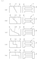
- Figs. 3 (a) to 3 (e) are a front view (right view) and a plan view (left view) of the magnetic core component.
- the respective half-members have a shape in which the right triangular portion (tapered portion) and the leg portion are combined when seen in plan view.
- the joining surface 1d is formed as one plane inclined with respect to the axial direction of the winding shaft portion. Compared to the structure of Fig. 1(a) , the inclination angle of the joining surface 1d is slightly small, and the joining area is also slightly small.
- the joining surface 1d is a compound surface including surfaces (two) perpendicular to the axial direction of the winding shaft portion, and one surface inclined with respect to the axial direction of the winding shaft portion.
- the joining area becomes large compared to when configured from only surfaces perpendicular to the axial direction of the winding shaft portion.
- the inclination angle of the inclined surface differs between Fig. 3(b) and Fig. 3(c) .
- the joining surface 1d is a compound surface including surfaces (two) perpendicular to the axial direction of the winding shaft portion, and a surface that lies along the axial direction of the winding shaft portion.
- the joining area becomes large by an area of the surface lying along the axial direction of the winding shaft portion compared to when configured from only surfaces perpendicular to the axial direction of the winding shaft portion.
- the area of the surface that lies along the axial direction of the winding shaft portion differs between Fig. 3 (d) and Fig. 3(e) .
- the half-members 2, 3 have the same shape in any of Figs. 3(a) to 3(e) , and can be manufactured with one type of mold. Furthermore, as described above, a wide joining area can be ensured in any case, and the actual contacting area also becomes large, so that the gap between the members can be reduced and the leakage flux can be suppressed compared to the shape shown in Fig. 4(b) .
- the half-member is a magnetic body, and the method for manufacturing the same is not particularly limited, but a compression molded body of a magnetic material is preferably adopted as it can be inexpensively manufactured and can be easily miniaturized compared to injection molded body.
- a compression molded body of a magnetic material is preferably adopted as it can be inexpensively manufactured and can be easily miniaturized compared to injection molded body.
- the magnetic core component of the present invention is formed as a member having a simple shape as described above, it can be sufficiently molded even with compression molding.
- the half-member uses, as a raw material, pure iron soft magnetic material including iron powder and iron nitride powder; iron-base alloy soft magnetic material including Fe-Si-Al alloy (sendust) powder, super sendust powder, Ni-Fe alloy (permalloy) powder, Co-Fe alloy powder, and Fe-Si-B alloy powder; and magnetic material including ferrite magnetic material, amorphous magnetic material, and microcrystalline material.
- the ferrite magnetic material includes manganese zinc ferrite, nickel zinc ferrite, copper zinc ferrite, spinel ferrite having a spinel type crystalline structure such as magnetite, barium ferrite, hexagonal ferrite such as strontium ferrite, garnet ferrite such as yttrium iron garnet, and the like.
- the amorphous magnetic material includes iron alloy, cobalt alloy, nickel alloy, mixed alloy amorphous thereof, and the like.
- Examples of an oxide that forms an insulating coating on a particle surface of the magnetic material to become the raw material include an oxide of insulating metal or metalloid including Al 2 O 3 , Y 2 O 3 , MgO, ZrO 2 , and the like, glass, and a mixture thereof.
- powder coating method such as mechano-fusion, wet thin-film production method such as electroless plating and sol-gel method, or dry thin-film production method such as sputtering can be used.
- An average particle diameter of the raw material powder is preferably 1 to 150 ⁇ m, and more preferably 5 to 100 ⁇ m. If the average particle diameter is smaller than 1 ⁇ m, compressibility (scale indicating easiness of hardening of powder) at the time of pressurization molding lowers, and the material strength after burning significantly lowers. If the average particle diameter is greater than 150 ⁇ m, the iron loss in a high frequency region becomes large, and the magnetic property (frequency property) lowers.
- the half-member which is a compression molded body, can be manufactured as follows: a raw material powder simple body of magnetic material, where the insulating coating is formed on the particle surface, or a powder in which the thermosetting resin such as an epoxy resin is combined in the raw material powder is press-molded at a predetermined pressurization force to obtain a powder body; and this powder body is burned. Since the half-members have the same shape, the mold used is one type. When using an amorphous alloy powder for the raw material, the burning temperature needs to be lower than a crystallization start temperature of the amorphous alloy. Furthermore, when using the powder combined with the thermosetting resin, the burning temperature needs to be in a hardening temperature range of the resin.
- the two obtained half-members are joined to complete the magnetic core component.
- the joining of the members can be carried out using an adhesive and the like in addition to the fitting-in by the positioning shape described above.
- a solventless epoxy adhesive that can be closely attached to each other is preferred for the adhesive.
- the winding wire is wound around the winding shaft portion to form the coil, thus obtaining the chip inductor with an inductor function.
- a copper enamel wire can be used for the winding wire, and examples of the type of wire that can be used include urethane wire (UEW), formal wire (PVF), polyester wire (PEW), polyester imide wire (EIW), polyamide imide wire (AIW), polyimide wire (PIW), double coated wire combining the same, or self-welding wire, litz wire, and the like.
- the polyamide imide wire (AIW), the polyimide wire (PIW), and the like excelling in heat resistance are preferred.
- the cross-sectional shape of the copper enamel wire that can be adopted may be round or square. The known method can be adopted for the manner of winding the coil and the like.
- the magnetic core component of the present invention can suppress the leakage flux while suppressing the number of molds required at the time of molding, and thus can be suitably used as a core for the chip inductor used in the electronic circuit of various types of electric/electronic equipment.
Landscapes
- Engineering & Computer Science (AREA)
- Power Engineering (AREA)
- Coils Or Transformers For Communication (AREA)
Applications Claiming Priority (2)
| Application Number | Priority Date | Filing Date | Title |
|---|---|---|---|
| JP2014203334A JP2016072569A (ja) | 2014-10-01 | 2014-10-01 | 磁性コア部品およびチップインダクタ |
| PCT/JP2015/076673 WO2016052257A1 (ja) | 2014-10-01 | 2015-09-18 | 磁性コア部品およびチップインダクタ |
Publications (2)
| Publication Number | Publication Date |
|---|---|
| EP3203488A1 true EP3203488A1 (de) | 2017-08-09 |
| EP3203488A4 EP3203488A4 (de) | 2018-06-13 |
Family
ID=55630297
Family Applications (1)
| Application Number | Title | Priority Date | Filing Date |
|---|---|---|---|
| EP15845926.3A Withdrawn EP3203488A4 (de) | 2014-10-01 | 2015-09-18 | Magnetkernkomponente und chipinduktor |
Country Status (5)
| Country | Link |
|---|---|
| US (1) | US20180233268A1 (de) |
| EP (1) | EP3203488A4 (de) |
| JP (1) | JP2016072569A (de) |
| CN (1) | CN106688064A (de) |
| WO (1) | WO2016052257A1 (de) |
Families Citing this family (3)
| Publication number | Priority date | Publication date | Assignee | Title |
|---|---|---|---|---|
| JP6615155B2 (ja) * | 2017-06-27 | 2019-12-04 | 矢崎総業株式会社 | ノイズ低減ユニット |
| JP6630315B2 (ja) * | 2017-06-27 | 2020-01-15 | 矢崎総業株式会社 | ノイズ低減ユニット |
| FR3082351B1 (fr) * | 2018-06-08 | 2021-10-22 | Valeo Systemes De Controle Moteur | Composant formant au moins deux inductances |
Family Cites Families (9)
| Publication number | Priority date | Publication date | Assignee | Title |
|---|---|---|---|---|
| JPH0547563A (ja) * | 1991-08-09 | 1993-02-26 | Tokin Corp | インダクタ及びその製造方法 |
| JPH05299273A (ja) * | 1992-04-16 | 1993-11-12 | Mitsubishi Electric Corp | チョークコイル |
| JPH0677059A (ja) * | 1992-08-26 | 1994-03-18 | Nippon Steel Corp | トランスのコア |
| JPH06333745A (ja) * | 1993-05-25 | 1994-12-02 | Tokin Corp | チップ型インダクタ用コア |
| WO2002089156A1 (en) * | 2001-04-26 | 2002-11-07 | Coilcraft, Incorporated | Surface mountable electronic component |
| US7785424B2 (en) * | 2004-08-23 | 2010-08-31 | Nippon Kagaku Yakin Co., Ltd. | Method of making a magnetic core part |
| CN101243594B (zh) * | 2005-10-24 | 2012-07-04 | 松下电器产业株式会社 | 电容电动机及其制造方法 |
| WO2009008213A1 (ja) * | 2007-07-11 | 2009-01-15 | Murata Manufacturing Co., Ltd. | コモンモードチョークコイル |
| CN103310947A (zh) * | 2013-06-26 | 2013-09-18 | 华为技术有限公司 | 磁性器件 |
-
2014
- 2014-10-01 JP JP2014203334A patent/JP2016072569A/ja active Pending
-
2015
- 2015-09-18 US US15/516,411 patent/US20180233268A1/en not_active Abandoned
- 2015-09-18 CN CN201580053369.1A patent/CN106688064A/zh active Pending
- 2015-09-18 WO PCT/JP2015/076673 patent/WO2016052257A1/ja not_active Ceased
- 2015-09-18 EP EP15845926.3A patent/EP3203488A4/de not_active Withdrawn
Also Published As
| Publication number | Publication date |
|---|---|
| EP3203488A4 (de) | 2018-06-13 |
| US20180233268A1 (en) | 2018-08-16 |
| WO2016052257A1 (ja) | 2016-04-07 |
| CN106688064A (zh) | 2017-05-17 |
| JP2016072569A (ja) | 2016-05-09 |
Similar Documents
| Publication | Publication Date | Title |
|---|---|---|
| EP2879139B1 (de) | Zusammengesetzter magnetkern und magnetisches element | |
| TWI484513B (zh) | 層壓電磁元件總成 | |
| EP3352182B1 (de) | Magnetisches element | |
| JP5971231B2 (ja) | コモンモードチョークコイル及びその製造方法 | |
| US20130088317A1 (en) | Reactor and method of manufacturing the same | |
| EP3125259B1 (de) | Magnetisches element | |
| US10650951B2 (en) | Magnetic element | |
| WO2015115318A1 (ja) | 電子部品 | |
| US9978504B2 (en) | Coil device | |
| US20180233268A1 (en) | Magnetic core component and chip inductor | |
| CN107887106B (zh) | 线圈部件 | |
| CN114765090B (zh) | 线圈装置 | |
| US20200402707A1 (en) | Magnetic element | |
| US20170032886A1 (en) | Coil electronic component and method of manufacturing the same | |
| WO2017047740A1 (ja) | 磁性素子 | |
| US20180286553A1 (en) | Coil device | |
| US20170062116A1 (en) | Coil electronic component and method of manufacturing the same | |
| US20260004965A1 (en) | Coil device | |
| WO2024253007A1 (ja) | インダクタ及びインダクタの製造方法 |
Legal Events
| Date | Code | Title | Description |
|---|---|---|---|
| STAA | Information on the status of an ep patent application or granted ep patent |
Free format text: STATUS: THE INTERNATIONAL PUBLICATION HAS BEEN MADE |
|
| PUAI | Public reference made under article 153(3) epc to a published international application that has entered the european phase |
Free format text: ORIGINAL CODE: 0009012 |
|
| STAA | Information on the status of an ep patent application or granted ep patent |
Free format text: STATUS: REQUEST FOR EXAMINATION WAS MADE |
|
| 17P | Request for examination filed |
Effective date: 20170421 |
|
| AK | Designated contracting states |
Kind code of ref document: A1 Designated state(s): AL AT BE BG CH CY CZ DE DK EE ES FI FR GB GR HR HU IE IS IT LI LT LU LV MC MK MT NL NO PL PT RO RS SE SI SK SM TR |
|
| AX | Request for extension of the european patent |
Extension state: BA ME |
|
| DAV | Request for validation of the european patent (deleted) | ||
| DAX | Request for extension of the european patent (deleted) | ||
| A4 | Supplementary search report drawn up and despatched |
Effective date: 20180514 |
|
| RIC1 | Information provided on ipc code assigned before grant |
Ipc: H01F 27/06 20060101ALI20180508BHEP Ipc: H01F 27/255 20060101ALI20180508BHEP Ipc: H01F 27/26 20060101ALI20180508BHEP Ipc: H01F 27/24 20060101AFI20180508BHEP Ipc: H01F 37/00 20060101ALI20180508BHEP Ipc: H01F 17/04 20060101ALI20180508BHEP |
|
| STAA | Information on the status of an ep patent application or granted ep patent |
Free format text: STATUS: THE APPLICATION IS DEEMED TO BE WITHDRAWN |
|
| 18D | Application deemed to be withdrawn |
Effective date: 20181212 |