EP3203893B1 - Buse de sol pour nettoyeur à vapeur et nettoyeur à vapeur - Google Patents
Buse de sol pour nettoyeur à vapeur et nettoyeur à vapeur Download PDFInfo
- Publication number
- EP3203893B1 EP3203893B1 EP14784038.3A EP14784038A EP3203893B1 EP 3203893 B1 EP3203893 B1 EP 3203893B1 EP 14784038 A EP14784038 A EP 14784038A EP 3203893 B1 EP3203893 B1 EP 3203893B1
- Authority
- EP
- European Patent Office
- Prior art keywords
- axis
- tilt
- bearing shaft
- steam cleaning
- section
- Prior art date
- Legal status (The legal status is an assumption and is not a legal conclusion. Google has not performed a legal analysis and makes no representation as to the accuracy of the status listed.)
- Active
Links
- 238000013020 steam cleaning Methods 0.000 title claims description 75
- 230000008878 coupling Effects 0.000 claims description 96
- 238000010168 coupling process Methods 0.000 claims description 96
- 238000005859 coupling reaction Methods 0.000 claims description 96
- 239000007788 liquid Substances 0.000 claims description 25
- 239000012530 fluid Substances 0.000 claims description 19
- 238000004891 communication Methods 0.000 claims description 16
- 238000007789 sealing Methods 0.000 claims description 14
- 239000004033 plastic Substances 0.000 claims description 5
- 229920003023 plastic Polymers 0.000 claims description 5
- 238000004140 cleaning Methods 0.000 description 7
- 239000000463 material Substances 0.000 description 5
- 238000010276 construction Methods 0.000 description 3
- XLYOFNOQVPJJNP-UHFFFAOYSA-N water Substances O XLYOFNOQVPJJNP-UHFFFAOYSA-N 0.000 description 3
- 239000004744 fabric Substances 0.000 description 2
- 239000012459 cleaning agent Substances 0.000 description 1
- 230000006835 compression Effects 0.000 description 1
- 238000007906 compression Methods 0.000 description 1
- 238000010586 diagram Methods 0.000 description 1
- 230000000694 effects Effects 0.000 description 1
- 229920001971 elastomer Polymers 0.000 description 1
- 239000000806 elastomer Substances 0.000 description 1
- 230000002349 favourable effect Effects 0.000 description 1
- 210000003746 feather Anatomy 0.000 description 1
- 238000010438 heat treatment Methods 0.000 description 1
- 238000002347 injection Methods 0.000 description 1
- 239000007924 injection Substances 0.000 description 1
- 238000009434 installation Methods 0.000 description 1
- ORQBXQOJMQIAOY-UHFFFAOYSA-N nobelium Chemical compound [No] ORQBXQOJMQIAOY-UHFFFAOYSA-N 0.000 description 1
Images



Classifications
-
- A—HUMAN NECESSITIES
- A47—FURNITURE; DOMESTIC ARTICLES OR APPLIANCES; COFFEE MILLS; SPICE MILLS; SUCTION CLEANERS IN GENERAL
- A47L—DOMESTIC WASHING OR CLEANING; SUCTION CLEANERS IN GENERAL
- A47L13/00—Implements for cleaning floors, carpets, furniture, walls, or wall coverings
- A47L13/10—Scrubbing; Scouring; Cleaning; Polishing
- A47L13/20—Mops
- A47L13/22—Mops with liquid-feeding devices
- A47L13/225—Steam mops
Definitions
- the present invention relates to a steam cleaning device floor nozzle for a steam cleaning device, which comprises a storage tank for a liquid, a steam generating device that is in fluid communication with the storage tank for generating a liquid vapor, and a connecting line that is in fluid communication with the steam generating device, which steam cleaning device floor nozzle has at least one nozzle body a steam outlet opening and a coupling element, which is coupled to the nozzle body, in particular in an articulated manner, and which defines a connection element channel and has a coupling section, which coupling section is temporarily or permanently coupled to the steam cleaning device floor nozzle with the connection, in particular tubular or tubular connection line, which is in fluid communication with the steam generation device furthermore a swivel joint defining an axis of rotation for rotating the coupling section and the nozzle body relative to one another other around the axis of rotation, a tilting joint defining a tilting axis extending transversely to the axis of rotation for pivoting the coupling section and the nozzle body relative
- the present invention further relates to a steam cleaning device with a storage tank for a liquid, a steam generating device that is in fluid communication with the storage tank for generating a liquid vapor, and a floor nozzle that is in fluid communication with the steam generating device via a connecting line.
- Steam cleaning devices with steam cleaning device floor nozzles of the type described in the introduction are known in various designs. They make it possible to apply hot steam in particular, which loosens dirt, for cleaning surfaces of different types, for example floors. Water is preferably evaporated as the liquid so that hot water vapor is applied to the surfaces to be cleaned and, for example, wiped with a cloth stretched over the floor nozzle.
- the basic structure of steam cleaning device floor nozzles is derived from a simple scrubber. However, such a structure only allows limited ergonomic handling. In particular, the efficient cleaning of floors under furniture is only possible to a limited extent with known steam cleaning device floor nozzles.
- a surface cleaning device with a swiveling distributor pipe is from the EP 2 494 904 A2 known.
- the coupling section is connected to a hose or extension tube
- the floor nozzle can be pivoted relative to the coupling section independently of one another about two axes, namely about the axis of rotation and the tilting axis. So can the coupling section and in particular with this
- extension tube coupled in a rotationally fixed manner can be tilted without the steam cleaning device floor nozzle lifting off from the surface to be cleaned. You can easily apply liquid vapor to a floor under flat furniture.
- the tilting joint offers the advantage of tipping the coupling section with an extension tube coupled to it in the manner described, it has the disadvantage, however, that the nozzle body lifts off the surface to be cleaned or at least tends to do so if the steam cleaning device floor nozzle is used by a user with a with the coupling section coupled extension tube is pulled over the surface to be cleaned. In order to prevent such lifting, i.e.
- the braking device is provided, which essentially prevents the nozzle body from pivoting independently of the coupling section about the tilt axis or at least restricted such that an underside of the nozzle body, over which a cleaning cloth in particular can be stretched, no longer lifts off the floor.
- the tilting joint thus enables a direct contact of an underside of the nozzle body on the surface to be cleaned, even with the coupling section severely tilted, with an extension tube connected to it, in which case the braking device effectively prevents the steam cleaning device floor nozzle from lifting off from the surface to be cleaned or pivoted relative to the coupling section about the tilt axis.
- connection element has a tilt joint section which is coupled to the nozzle body so as to be pivotable about the tilt axis in order to form the tilt joint.
- a connection element can thus be coupled to the nozzle body in a pivotable manner with the tilting joint section.
- the tilt joint section and the coupling section are coupled to one another so as to be rotatable relative to one another about the axis of rotation. In particular, they can be permanently coupled to one another or also releasably connected to one another. This makes it possible, in particular, to disassemble the steam cleaning device floor nozzle for cleaning purposes.
- the coupling section is tubular or essentially tubular. In particular, this makes it possible to conduct liquid vapor through the coupling section. In particular, a particularly compact construction of the steam cleaning device floor nozzle can be achieved.
- the tilting joint section is preferably tubular or essentially tubular. It is thus possible, in particular, to conduct liquid vapor through the connection element from the coupling section to the tilting joint section and through it, so that the latter can emerge from the nozzle body through the at least one steam outlet opening.
- the rocker joint section defines a longitudinal axis of the rocker joint section
- the coupling section defines a longitudinal axis of the coupling section
- the longitudinal axis of the rocker joint section and the longitudinal axis of the coupling section run parallel or transversely to one another.
- the longitudinal axis of the articulated joint section and the longitudinal axis of the coupling section can also coincide. If the two axes run transversely to one another, they can in particular be aligned in such a way that a particularly ergonomic posture is possible for the user when using the steam cleaning device.
- the coupling section longitudinal axis can define a longitudinal axis which is extended by an extension tube which is connected to the connection element.
- an angled introduction of liquid vapor through the coupling section into the tilting joint section and into the nozzle body is also possible.
- the steam cleaning device floor nozzle can be designed to be particularly compact if the tilting joint section defines the axis of rotation.
- the longitudinal axis of the articulated joint section can define the axis of rotation. This configuration makes it possible, for example, to rotate the coupling section relative to the tilt joint section about the axis of rotation.
- the tilt joint section comprises a first coupling member
- the coupling section comprises a second coupling member and if the first and the second coupling member are in a non-positive and / or positive engagement with one another.
- the first and second coupling members make it possible, in particular, to couple the tilting joint section and the coupling joint section to one another in a non-positive and / or positive manner.
- a securing device can additionally be provided, which either allows the coupling members to be separated from one another or makes it temporarily or permanently impossible after installation of the steam cleaning device floor nozzle.
- the coupling members can be designed in such a way that they are held immovably relative to one another axially, but can be rotated in the circumferential direction, in particular about the axis of rotation of the swivel joint.
- the swivel joint can also be formed by the mutually engaging first and second coupling members.
- a particularly compact design of the steam cleaning device floor nozzle can be achieved if the first and second coupling members are designed in the form of interlocking pipe sections. Furthermore, such a configuration enables liquid vapor to be passed through a coupling point of the connection element formed by the first and second coupling elements.
- the first and second coupling members are preferably coupled to one another so as to be rotatable relative to one another about the axis of rotation.
- the swivel joint can be formed in particular by the first and second coupling members which are in engagement with one another.
- first and second coupling members define coinciding longitudinal axes, which coincide with the longitudinal axis of the articulation section. In this way, they can be brought into engagement with one another in a simple and defined manner, for example inserted into one another become. Furthermore, the two coupling members can also be rotated relative to one another in a simple manner, in particular in order to form or define the swivel joint.
- the longitudinal axis of the tilt joint section and the longitudinal axis of the coupling section enclose an angle of inclination which is in a range from approximately 0 ° to approximately 90 °.
- the angle of inclination is preferably in a range from approximately 25 ° to approximately 35 °.
- the nozzle body advantageously comprises an underside and the tilt axis runs parallel or substantially parallel to the underside.
- the steam cleaning device floor nozzle can be guided and moved in a targeted manner by a user.
- this enables ergonomic and intuitive handling of the steam cleaning device floor nozzle.
- the axis of rotation intersects the tilting axis.
- the axis of rotation intersects the tilt axis at right angles. In particular, this makes it possible to pivot the coupling section relative to the nozzle body in two directions that are linearly independent of one another.
- the tilt joint comprises a bearing shaft which is pivotably mounted on the nozzle body and defines the tilt axis.
- the bearing shaft enables an articulated coupling of the tilt joint section and thus of the connection element to the nozzle body in a simple manner.
- the bearing shaft is preferably hollow and is in fluid communication with the connecting element channel. This configuration makes it possible, in particular, to conduct liquid vapor through the connection element into the bearing shaft and out of it in a targeted manner into the nozzle body, so that the liquid vapor can then, depending on the configuration of the nozzle body, in turn in a targeted manner exit through the at least one steam outlet opening, preferably directly in the direction of the surface to be cleaned.
- the braking device advantageously comprises at least one brake member which interacts with the tilt joint section or the bearing shaft on the one hand and / or with the nozzle body on the other hand.
- a brake member makes it possible, in particular, to interact directly or indirectly with components of the steam cleaning device floor nozzle coupled to the tilt joint or with parts forming the tilt joint. A movement of the coupling section and of the nozzle body relative to one another about the tilt axis can thus be braked directly, that is to say in particular made more difficult.
- this can prevent liquid vapor from emerging from the at least one steam outlet opening of the nozzle body in the direction of the surface to be cleaned, so that the nozzle body automatically swivels relative to the connection element due to a recoil about the tilting axis or when the steam cleaning device floor nozzle is pulled back, the is coupled with an extension tube, due to a pivoting movement about the tilt axis.
- Non-positive can in this context mean in particular that the brake member presses against the tilting joint section or the bearing shaft on the one hand and the nozzle body on the other hand in order to generate a braking force or braking torque oriented transversely to the pressing direction, which counteracts a pivoting movement of the nozzle body and the connecting section about the tilting axis.
- the braking device can be designed in a particularly simple and compact manner if the braking member is designed in the form of an annular disk or in the form of a prestressing element which is supported on the one hand on the tilt joint section or on the bearing shaft and on the other hand on the nozzle body.
- a braking force can be generated and introduced parallel to the tilt axis in order to generate a braking torque or frictional torque which counteracts a pivoting movement of the coupling section and the nozzle body relative to one another.
- a prestressing element held on the nozzle body presses the brake member against the tilt joint section or the bearing shaft. If one tries to pivot the nozzle body relative to the coupling section about the tilt axis, the force exerted by the braking member in conjunction with the prestressing element counteracts the pivoting movement in the form of a corresponding frictional force depending on the friction coefficients of the materials lying against one another.
- a particularly compact design of the steam cleaning device floor nozzle can be achieved if the brake member is arranged or designed to surround the bearing shaft.
- the brake member in the form of an annular disk can surround the bearing shaft as well as a prestressing element in the form of a torsion or coil spring.
- the prestressing element is arranged or designed to act parallel or transversely to the tilt axis.
- the biasing Element acting perpendicular to the tilt axis may be arranged or formed.
- the prestressing element is designed in the form of an elastic element .
- the elastic element can be designed to be resilient.
- the steam cleaning device floor nozzle can be designed particularly inexpensively if the prestressing element is designed in the form of a spring or an elastic plastic body.
- the spring is in the form of a helical spring.
- this makes it possible to arrange or design the spring surrounding the bearing shaft on the steam cleaning device floor nozzle.
- the helical spring preferably defines a helical spring axis which coincides with the tilt axis.
- this configuration can be implemented by the helical spring surrounding the position shaft or pressing on an end face of the bearing shaft or an annular flange of the bearing shaft.
- the bearing shaft and the tilt joint section are formed in one piece.
- this unit can be injection molded from a plastic.
- the nozzle body comprises a bearing device and that the bearing shaft and / or the tilt joint section on the bearing device are pivotally mounted about the tilt axis.
- the bearing device it is possible in particular in a simple manner to connect the connecting element and the nozzle body to one another, for example in such a way that the tilting joint section is arranged on the nozzle body so as to be pivotable about the tilt axis.
- a symmetrical steam cleaning device floor nozzle can be designed in a simple manner, in particular in that the bearing device comprises at least two bearing shaft receptacles for receiving a respective bearing shaft section of the bearing shaft.
- the bearing shaft receptacles can have hollow cylindrical sections which can receive a cylindrical or substantially cylindrical bearing shaft section.
- the bearing shaft receptacles can be designed to receive end sections of the bearing shaft in the manner of a blind hole.
- the bearing shaft is sealed relative to the bearing device.
- the bearing shaft can be sealed relative to the bearing device by at least one sealing element. Sealing elements in the form of sealing rings made of plastics, in particular elastomers, are particularly conceivable here.
- the bearing shaft has a first stop surface, which bears against a standing surface surrounding the bearing shaft receptacle, and a second stop surface, on which the prestressing element is supported.
- This configuration makes it possible, in particular, to apply a pressure force acting parallel to the tilt axis in order to generate a frictional force acting in the circumferential direction with respect to the tilt axis or a friction torque oriented parallel to the tilt axis, which counteracts a pivoting movement of the coupling section and of the nozzle body relative to one another.
- a particularly compact design of the steam cleaning device floor nozzle can be achieved if the first and second stop surfaces are away from one another or to point to each other.
- the stop surfaces can be formed on projections which are arranged or formed on the bearing shaft, for example ring flanges pointing radially away from the tilt axis.
- the prestressing element can be designed in the form of a pressure or a tension member.
- a particularly good braking effect can be achieved if the prestressing element is supported on the one hand on the brake member and on the other hand on the second stop surface.
- This configuration makes it possible, in particular, to select a brake member made of a material which has an optimal coefficient of friction in cooperation with the material from which the nozzle body, the bearing shaft or the tilt joint section are formed in order to set the required braking force or the required braking torque in the desired manner to be able to.
- the brake member preferably presses against an annular or substantially annular end face of the bearing device surrounding the bearing shaft.
- the end face can surround the bearing shaft holder.
- a steam cleaning device of the type described at the outset in that it comprises one of the steam cleaning device floor nozzles described above.
- the steam cleaning device then also has the advantages described above in connection with preferred embodiments of steam cleaning device floor nozzles.
- the connecting line comprises a connecting hose and / or a connecting pipe.
- a coupling or grip piece can be arranged or formed at the end of the connecting hose, which can be coupled directly to the connecting element or to an extension tube, which in turn can be coupled to the connecting element at its other end is.
- this allows the steam cleaning device to be handled similarly to a vacuum cleaner.
- no braking devices as proposed according to the invention have to be provided, since a suction flow generated by a suction device generates a negative pressure in the area of the suction nozzle during operation of the vacuum cleaner, which causes an underside of the suction nozzle to be pressed against the surface to be extracted.
- the problem described above of lifting the steam cleaning device floor nozzle does not arise with a vacuum cleaner.
- the connecting line comprises a connecting section and if the connecting section can be temporarily coupled or permanently coupled to the connecting element.
- the connection section can be temporarily coupled or permanently coupled to the coupling section of the connection element.
- the connecting section can in particular form a connection or grip piece at the end of a connection hose or at one of the ends of an extension tube, which can be connected to the connection piece of the extension hose on the one hand and the connection element of the steam cleaning device floor nozzle on the other hand.
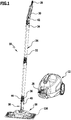
- FIG. 1 schematically shows a steam cleaning device 10, generally designated by the reference number 10. It comprises a mobile housing 12, in which a storage tank 14 and a steam generating device 18, which is in fluid communication with it via a connecting line 16, are arranged.
- the steam generating device 18 preferably comprises an electrically operated heating device 20.
- An outlet 22 of the steam generating device 18 is connected via an external connecting line 24 to a steam cleaning device floor nozzle 26, hereinafter referred to as floor nozzle 26.
- the connecting line 24 comprises a flexible connecting hose 28, on the end of which pointing away from the housing 12 a handle 30 is arranged.
- switching elements can be arranged or formed on the grip piece 30 in order to control the delivery of liquid vapor generated by the steam generating device 18 through the outlet 22.
- An extension tube 32 can optionally also be part of the connecting line 24. This can in particular be made telescopic.
- the extension tube 32 can be coupled with the handle 30 with a first end 34 and with a second end 36 with a connecting element 38 of the floor nozzle 26, in particular with a tubular coupling section 40 of the connecting element 38.
- the handle 30 and also the end 36 each form connecting sections 42 and 44, which are temporarily connectable or permanently coupled to the connecting element 38, in particular to the coupling section 40 thereof. It goes without saying that the handle 30 can also be coupled directly to the connection element 38, so that the floor nozzle 26 can be moved directly with the handle 30 by a user over a surface to be cleaned which is to be loaded with liquid vapor.
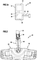
- the floor nozzle 26 comprises a nozzle body 46, which is coupled to the connection element 40, in an articulated manner.
- Fluid channels 48 are formed on the nozzle body 46 and are in fluid communication with steam outlet openings which are formed on an underside 52 of the nozzle body 46.
- connection element 38 further comprises a tilt joint section 54, which is coupled to form a tilt joint 56 with the nozzle body 46 so as to be pivotable about a tilt axis 58.
- the rocker joint section 54 is also tubular and defines a longitudinal axis 60 of the rocker joint section.
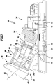
- the coupling section 40 defines a coupling section longitudinal axis 62 Figures 1 to 7
- the longitudinal axis 60 of the articulated joint section and the longitudinal axis of the coupling section extend 62 across. They are inclined relative to one another and enclose an inclination angle 64, which in particular can be in a range from approximately 0 ° to approximately 50 °. In the in the Figures 1 to 7 In the illustrated embodiment, the angle of inclination 64 is approximately 30 °.
- the coupling section 40 and the tilt joint section 54 can be rotated relative to one another about an axis of rotation 66.
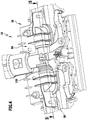
- a swivel joint 68 defining the axis of rotation 66 for rotating the coupling section 40 and the swivel joint section 54 and thus also the nozzle body 46 relative to one another about the swivel axis 66 is formed by a first coupling member 70 of the swivel joint section 60 and a second coupling member 72 of the coupling section 40.
- the first and second coupling members 70 and 72 are each designed in the form of a tube section, in such a way that they engage in one another in a connecting position. This is realized in such a way that the first coupling member 70 defines an inner diameter so that the second coupling member 72 can be inserted into it.
- a sealing element 78 in the form of a sealing ring is inserted in an annular groove 76 on the second coupling element 72, which sealing element seals the second coupling element 72 relative to the first coupling element 70. Liquid vapor can thus flow through the connecting line 24 through the connection element 38.
- first and second coupling members 70 and 72 are coupled to one another so as to be rotatable relative to one another about the axis of rotation 66, and are held essentially immovably to one another axially, that is to say parallel to the axis of rotation 60.
- Longitudinal axes of the first and second coupling members 70 and 72 coincide and define the longitudinal pivot axis section 60.
- an optional embodiment of the floor nozzle 26 can provide that the longitudinal axis 60 of the articulated joint section and the longitudinal axis 62 of the coupling section run parallel to one another, in particular coincide.
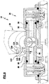
- the tilt joint section 54 has a tubular bearing shaft 80 which defines a longitudinal axis which forms the tilt axis 58. It is in fluid communication with the connecting element channel 74, so that liquid vapor can flow through the connecting element channel 74 into a bearing shaft channel 82 defined in its interior by the bearing shaft 80.
- the tilt joint 56 comprises on the one hand the bearing shaft 80 and a bearing device 84 for the bearing shaft 80 which is arranged or formed on the nozzle body 46.
- the bearing device 84 comprises two bearing shaft receptacles 86 which are essentially in the form of short hollow cylindrical tube sections.
- the bearing shaft receptacles 86 are closed in directions pointing away from one another and opened to point towards one another. They define annular end faces 88 and 90 which point towards one another and run parallel to one another and to the axis of rotation 66.
- the bearing shaft receptacles 86 are also in fluid communication with the fluid channels 48.
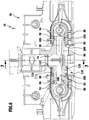
- An inner diameter of the bearing shaft receptacles 86 is adapted to an outer diameter of the bearing shaft 80. Free ends 92 and 94 of the bearing shaft 80 are each provided with an annular groove 96 and 98, in each of which a sealing element 100 or 102 is inserted. The sealing elements 100 and 102 seal the bearing shaft 80 relative to the bearing shaft receptacles 86.
- the bearing shaft 80 also has an annular flange 104 with an annular stop surface 106 which bears on the end face 90.
- a brake member 108 of a brake device designated overall by reference numeral 110 bears against the end face 88.
- the brake member 108 is designed in the form of an annular disk 112, which carries a short, hollow cylindrical connecting piece 114 pointing in the direction of the end face 90.
- the disk 112 protrudes somewhat in the radial direction with respect to the tilt axis 58 over the connection piece 114 and defines a stop surface 116 pointing in the direction of the end face 90.
- a prestressing element 118 of the braking device 110 is supported on this with a first end thereof.
- a second end of the prestressing element 118 is supported on an annular flange 120 of the tilt joint section 54, more precisely on an annular stop surface 122 of the annular flange 120, which points in the direction of the end face 88.
- the prestressing element 118 is designed in the form of a spring 124, specifically in the form of a helical spring 126 which surrounds the bearing shaft 80 and is aligned with its longitudinal axis coaxially with the tilt axis 58.
- the helical spring 126 is designed in the form of a compression spring and thus on the one hand holds the stop surface 106 in contact with the end face 90 and an annular surface 128 of the brake member 108 on the end face 88.
- the prestressing element 118 is thus arranged to act parallel to the tilt axis 58.
- the brake member 108 is preferably formed from a plastic which has a greater coefficient of friction than the bearing shaft 80, so that between the ring surface 128 and the end face 88 when the pivot joint section 54 rotates relative to the nozzle body 46, greater frictional forces act than between the stop surface 106 and the End face 90. In this way, by appropriate choice of the material of the brake member 108, a braking force acting as a result of a pivoting of the tilt joint section 54 relative to the nozzle body 46 or a corresponding braking torque can be predefined.
- the prestressing element 118 offers a second possibility of adjusting the braking force or the braking torque, since the acting braking force or the braking torque are proportional to the acting spring force of the prestressing element 118.
- the brake member 108 in the form shown in the figures can also be dispensed with.
- the prestressing element 118 can itself form the brake member if it is supported on the one hand on the ring flange 120 and on the other hand directly on the end face 88.
- FIG 8 a schematic sectional view of a second exemplary embodiment of a floor nozzle 26 is shown, which differs in the mode of operation of the braking device 118 from the first to Figures 1 to 7 schematically shown floor nozzle 26 differs.
- the brake member 108 bears against the bearing shaft 80 between the end face 88 and the stop face 122. It is pressed against the bearing shaft 80 by a prestressing element 118, which is supported on a support body 130, which is optionally arranged or formed on the nozzle body 46 or on the connection element 38.
- the prestressing element is preferably designed in the form of a spring 124 and is dimensioned such that it presses the brake member 108 against the bearing shaft 80 with a defined force F.
- the direction of the force F points in the direction of the tilt axis 58.
- a longitudinal axis of the spring 124 can run in the radial direction with respect to the tilt axis 58 and intersect the tilt axis 58 transversely, in particular perpendicularly.
- the brake member 108 together with the prestressing element can also act at any other point on the bearing shaft 80 in the radial direction.
- a positioning of this braking device 110 can be individually adapted to a construction of the nozzle body 46 or can be provided depending on the space available on the floor nozzle 26.
- FIG 9 is schematically similar to a sectional view Figure 7 a further embodiment of a floor nozzle 26 is shown schematically.
- the illustrated embodiment of the floor nozzle 26 again consists in the design of the braking device 110.
- the braking member 108 bears on the bearing shaft 80 with a contact surface 132 which points in the direction of the tilt axis 58.
- the biasing element 118 in the form of a spring 124 surrounds a leg 134 of the brake member 108, which extends transversely to the tilt axis 58, and is supported on the one hand on the connecting element 38 and on the other hand on the brake member 108.
- the prestressing element 118 thus acts in a direction tangential to the bearing shaft 80.
- the brake member 108 is held on the nozzle body 46 in a manner not shown.
- the braking device 110 generates a braking torque M which counteracts this movement.
- a wipe 136 is preferably stretched over the floor nozzle 26. It is ideally permeable to the liquid vapor, so that the surface to be cleaned can be acted upon in the desired manner.
- the braking force generated by this or the braking torque counteracting a pivoting movement of the coupling section 40 relative to the nozzle body 46 about the tilt axis 58 is greater than a frictional force between the bearing shaft 80 and the bearing shaft receptacles 86.
- the sealing elements 100 and 102 on the one hand and the bearing shaft receptacles 86 acting frictional forces or moments of friction, which occur when the bearing shaft 80 rotates in the bearing shaft receptacles 86 are smaller than the braking or frictional forces or braking or frictional moments which are generated by the braking device 110.
- the optimum pressing force can be set by appropriate selection of the prestressing element 118 and the brake member 108 in order to generate the desired braking or frictional torque, which counteracts a pivoting movement of the nozzle body 46 relative to the coupling section 40 when the nozzle body 46 begins to lift off from it due to the application of liquid vapor to the surface to be cleaned.
- the storage tank 14 is preferably charged with water and optionally with a water-soluble cleaning agent which has a dirt-dissolving property.
- the steam generating device 18 can, in particular, be designed to generate hot liquid vapor which is conducted under a pressure which is higher than atmospheric pressure through the connecting line 24 to the floor nozzle 26 and through this to the steam outlet openings 50.
Landscapes
- Nozzles For Electric Vacuum Cleaners (AREA)
- Cleaning By Liquid Or Steam (AREA)
Claims (15)
- Buse de sol d'appareil de nettoyage à vapeur (26) pour un appareil de nettoyage à vapeur (10), lequel comprend un réservoir de stockage (14) pour un liquide, un dispositif de génération de vapeur (18) en liaison fluidique avec le réservoir de stockage pour générer une vapeur de liquide et une conduite de liaison (24) en liaison fluidique avec le dispositif de génération de vapeur (18), laquelle buse de sol d'appareil de nettoyage à vapeur (26) comprend un corps de buse (46) avec au moins un orifice de sortie de vapeur (50) et un élément de raccordement (38), accouplé, en particulier de manière articulée, au corps de buse (46), définissant un canal d'élément de raccordement (74) en particulier de manière articulée, avec une partie d'accouplement (40), laquelle partie d'accouplement (40) est accouplée en permanence ou peut être accouplée temporairement à la conduite de liaison (24), en particulier en forme de tuyau ou de tube, en liaison fluidique avec le dispositif de génération de vapeur (18), laquelle buse de sol d'appareil de nettoyage à vapeur (26) comprend en outre une articulation rotative (68) définissant un axe de rotation (66), pour faire tourner la partie d'accouplement (40) et le corps de buse (46) l'une par rapport à l'autre autour de l'axe de rotation (66), une articulation à basculement (56) définissant un axe de basculement (58) s'étendant transversalement à l'axe de rotation (66), pour faire pivoter la partie d'accouplement (40) et le corps de buse (46) l'une par rapport à l'autre autour de l'axe de basculement (58) et un dispositif de freinage (110) coopérant avec l'articulation à basculement (56) pour exercer une force de freinage ou un couple de freinage sur l'articulation à basculement (56), à l'encontre de l'action de laquelle la partie d'accouplement (40) et le corps de buse (46) peuvent pivoter l'une par rapport à l'autre autour de l'axe de basculement (58), dans laquelle l'élément de raccordement (38) présente une partie d'articulation à basculement (54), laquelle, pour réaliser l'articulation à basculement (56), est accouplée au corps de buse (46) de manière à pouvoir pivoter autour de l'axe de basculement (58), caractérisée en ce que la partie d'articulation à basculement (54) et la partie d'accouplement (40) sont accouplées l'une à l'autre de manière à pouvoir tourner l'une par rapport à l'autre autour de l'axe de rotation (66).
- Buse de sol d'appareil de nettoyage à vapeur selon la revendication 1, caractérisée en ce que la partie d'accouplement (40) est réalisée de manière tubulaire ou sensiblement tubulaire.
- Buse de sol d'appareil de nettoyage à vapeur selon la revendication 1 ou 2, caractérisée en ce que la partie d'articulation à basculement (54)a) est réalisée de manière tubulaire ou sensiblement tubulaire et/oub) définit un axe longitudinal de partie d'articulation à basculement (60), la partie d'accouplement (40) définit un axe longitudinal de partie d'accouplement (62) et l'axe longitudinal de partie d'articulation à basculement (60) et l'axe longitudinal de partie d'accouplement (62) s'étendent parallèlement ou transversalement l'un à l'autre,
dans laquelle en particulier l'axe longitudinal de partie d'articulation à basculement (60) et l'axe longitudinal de partie d'accouplement (62) forment un angle d'inclinaison (64), lequel se situe dans une plage d'environ 0° à environ 50°, en particulier dans une plage d'environ 25° à environ 35°,
et/ouc) définit l'axe de rotation (66),
dans laquelle en particulier l'axe longitudinal de partie d'articulation à basculement (60) définit l'axe de rotation (66). - Buse de sol d'appareil de nettoyage à vapeur selon l'une quelconque des revendications précédentes, caractérisée en ce que la partie d'articulation à basculement (54) comprend un premier organe d'accouplement (70), que la partie d'accouplement (40) comprend un deuxième organe d'accouplement (72) et que le premier et le deuxième organe d'accouplement (70, 72) sont en prise l'un avec l'autre à force et/ou par coopération de formes.
- Buse de sol d'appareil de nettoyage à vapeur selon la revendication 4, caractérisée en ce que le premier et le deuxième organe d'accouplement (70, 72)a) sont réalisés sous la forme de parties tubulaires s'imbriquant et/oub) sont accouplés l'un à l'autre de manière à pouvoir tourner l'un par rapport à l'autre autour de l'axe de rotation (66) et/ouc) définissent des axes longitudinaux coïncidents, lesquels coïncident avec l'axe longitudinal de partie d'articulation à basculement (60).
- Buse de sol d'appareil de nettoyage à vapeur selon l'une quelconque des revendications précédentes, caractérisée en ce quea) le corps de buse (46) comprend une face inférieure (52) et que l'axe de basculement (58) s'étend parallèlement ou sensiblement parallèlement à la face inférieure (52)
et/oub) l'axe de rotation (66) coupe l'axe de basculement (58), en particulier à angle droit,
et/ouc) l'articulation à basculement (56) comprend un arbre de palier (80), lequel est monté pivotant sur le corps de buse (46) et définit l'axe de basculement (58),
dans laquelle en particulier l'arbre de palier (80) est creux et est en liaison fluidique avec le canal d'élément de raccordement (74)
et/ou
l'arbre de palier (80) et la partie d'articulation à basculement (54) sont réalisés d'une seule pièce. - Buse de sol d'appareil de nettoyage à vapeur selon l'une quelconque des revendications précédentes, caractérisée en ce que le dispositif de freinage (110) comprend au moins un organe de freinage (108) coopérant avec la partie d'articulation à basculement (54) ou l'arbre de palier (80) d'une part et/ou avec le corps de buse (46) d'autre part.
- Buse de sol d'appareil de nettoyage à vapeur selon la revendication 7, caractérisée en ce quea) l'organe de freinage (108) est en prise à force avec la partie d'articulation à basculement (54) ou l'arbre de palier (80) d'une part et le corps de buse (46) d'autre part
et/oub) l'organe de freinage (108) est réalisé sous la forme d'un disque annulaire (112) ou sous la forme d'un élément de précontrainte (118), lequel s'appuie d'une part sur la partie d'articulation à basculement (54) ou sur l'arbre de palier (80) et d'autre part sur le corps de buse (46),
dans laquelle en particulier l'élément de précontrainte (118) est disposé ou réalisé de manière à agir parallèlement ou transversalement, en particulier perpendiculairement, à l'axe de basculement (58),
et/ouc) un élément de précontrainte (118) retenu sur le corps de buse (46) presse l'organe de freinage (108) contre la partie d'articulation à basculement (54) ou l'arbre de palier (80)
et/oud) l'organe de freinage (108) est disposé ou réalisé de manière à entourer l'arbre de palier (80),
dans laquelle en particulier l'élément de précontrainte (118) est disposé ou réalisé de manière à agir parallèlement ou transversalement, en particulier perpendiculairement, à l'axe de basculement (58). - Buse de sol d'appareil de nettoyage à vapeur selon l'une quelconque des alternatives b), c) ou d) de la revendication 8, caractérisée en ce quea) l'élément de précontrainte (118) est réalisé sous la forme d'un élément élastique, en particulier élastique à ressort et/oub) l'élément de précontrainte (118) est réalisé sous la forme d'un ressort (124) ou d'un corps plastique élastique
dans laquelle en particulier le ressort (124) est réalisé sous la forme d'un ressort hélicoïdal (126),
dans laquelle plus particulièrement le ressort hélicoïdal (126) définit un axe de ressort hélicoïdal, lequel coïncide avec l'axe de basculement (58). - Buse de sol d'appareil de nettoyage à vapeur selon l'une quelconque des revendications précédentes, caractérisée en ce que le corps de buse (46) comprend un dispositif support (84) et que l'arbre de palier (80) et/ou la partie d'articulation à basculement (54) sont montés sur le dispositif support (84) de manière à pouvoir tourner autour de l'axe de basculement (58).
- Buse de sol d'appareil de nettoyage à vapeur selon la revendication 10, caractérisée en ce quea) le dispositif support (84) comprend au moins deux logements d'arbre de palier (86) destinés à loger respectivement une partie d'arbre de palier de l'arbre de palier (80),
dans laquelle en particulier l'arbre de palier (80) présente une première surface de butée (106), qui s'applique contre une surface frontale (90) entourant l'un des logements d'arbre de palier (86), et une deuxième surface de butée (122), sur laquelle l'élément de précontrainte (118) s'appuie,
et/oub) l'arbre de palier (80) est étanchéifié par rapport au dispositif support (84), en particulier par au moins un élément d'étanchéité (102),
dans laquelle en particulier l'arbre de palier (80) présente une première surface de butée (106), qui s'applique sur une surface frontale (90) entourant l'un des logements d'arbre de palier (86), et une deuxième surface de butée (122), sur laquelle l'élément de précontrainte (118) s'appuie,
et/ouc) l'organe de freinage (108) effectue une pression contre une surface frontale (88) annulaire ou sensiblement annulaire, entourant l'arbre de palier (80), du dispositif support (84). - Buse de sol d'appareil de nettoyage à vapeur selon l'une quelconque des revendications précédentes, caractérisée en ce que la partie d'articulation à basculement (54) et la partie d'accouplement (40) sont étanchéifiées l'une par rapport à l'autre, en particulier par au moins un élément d'étanchéité (78).
- Buse de sol d'appareil de nettoyage à vapeur selon l'une quelconque des alternatives facultatives des alternatives a) ou b) de la revendication 11, caractérisée en ce quea) la première et la deuxième surface de butée (106, 122) sont orientées en s'écartant l'une de l'autre ou en direction l'une de l'autre
et/oub) l'élément de précontrainte (118) s'appuie d'une part sur l'organe de freinage (108) et d'autre part sur la deuxième surface de butée (122). - Appareil de nettoyage à vapeur (10) avec un réservoir de stockage (14) pour un liquide, un dispositif de génération de vapeur (18) en liaison fluidique avec le réservoir de stockage (14) pour générer une vapeur de liquide et une buse de sol (26) en liaison fluidique avec le dispositif de génération de vapeur (18) par l'intermédiaire d'une conduite de liaison (24), caractérisé en ce que la buse de sol (26) est réalisée sous la forme d'une buse de sol d'appareil de nettoyage à vapeur (26) selon l'une quelconque des revendications précédentes.
- Appareil de nettoyage à vapeur selon la revendication 14, caractérisé en ce que la conduite de liaison (24)a) comprend un tuyau de liaison (28) et/ou un tube de liaison (32)
et/oub) comprend une partie de liaison et que la partie de liaison (42, 44) peut être accouplée de manière temporaire ou est accouplée de manière permanente à l'élément de raccordement (38), en particulier à la partie d'accouplement (40) de celui-ci.
Applications Claiming Priority (1)
| Application Number | Priority Date | Filing Date | Title |
|---|---|---|---|
| PCT/EP2014/071763 WO2016055121A1 (fr) | 2014-10-10 | 2014-10-10 | Buse de sol d'un appareil de nettoyage à vapeur et appareil de nettoyage à vapeur |
Publications (2)
| Publication Number | Publication Date |
|---|---|
| EP3203893A1 EP3203893A1 (fr) | 2017-08-16 |
| EP3203893B1 true EP3203893B1 (fr) | 2020-06-17 |
Family
ID=51703152
Family Applications (1)
| Application Number | Title | Priority Date | Filing Date |
|---|---|---|---|
| EP14784038.3A Active EP3203893B1 (fr) | 2014-10-10 | 2014-10-10 | Buse de sol pour nettoyeur à vapeur et nettoyeur à vapeur |
Country Status (4)
| Country | Link |
|---|---|
| EP (1) | EP3203893B1 (fr) |
| JP (1) | JP2017529970A (fr) |
| CN (1) | CN106793907A (fr) |
| WO (1) | WO2016055121A1 (fr) |
Cited By (3)
| Publication number | Priority date | Publication date | Assignee | Title |
|---|---|---|---|---|
| US11910977B2 (en) | 2022-01-10 | 2024-02-27 | Bissell Inc. | Surface cleaning apparatus with steam |
| US11986139B2 (en) | 2022-02-02 | 2024-05-21 | Bissell Inc. | Extraction cleaner with steam |
| DE102023124185A1 (de) * | 2023-09-07 | 2025-03-13 | Alfred Kärcher SE & Co. KG | Heißfluidgerät und Aufsatz für Heißfluidgerät |
Families Citing this family (3)
| Publication number | Priority date | Publication date | Assignee | Title |
|---|---|---|---|---|
| DE102017107345A1 (de) | 2017-04-05 | 2018-10-11 | Alfred Kärcher SE & Co. KG | Bodendüse für einen Dampfreiniger und Dampfreiniger |
| DE102019133971A1 (de) * | 2019-12-11 | 2021-06-17 | Alfred Kärcher SE & Co. KG | Vorrichtung zum führen einer flexiblen leitung |
| CN114847827B (zh) * | 2022-03-15 | 2023-10-03 | 苏州克林威尔电器有限公司 | 带自清洁能力的蒸汽拖把 |
Family Cites Families (14)
| Publication number | Priority date | Publication date | Assignee | Title |
|---|---|---|---|---|
| JPS51148264A (en) * | 1975-06-12 | 1976-12-20 | Fukuba Kogyo Kk | Carpet cleaner |
| JPS60194925A (ja) * | 1984-03-19 | 1985-10-03 | 松下電器産業株式会社 | 電気掃除機の床ノズル |
| JPH07143947A (ja) * | 1993-11-22 | 1995-06-06 | Tec Corp | 電気掃除機の吸込口体 |
| JPH11104051A (ja) * | 1997-09-30 | 1999-04-20 | Nippon Dennetsu Co Ltd | オゾンスチーム放出器及びそれを用いたスチームクリーナ |
| JP3457909B2 (ja) * | 1999-02-08 | 2003-10-20 | シャープ株式会社 | 電気掃除機用吸込口体 |
| JP3868679B2 (ja) * | 1999-09-14 | 2007-01-17 | 株式会社日立製作所 | 電気掃除機 |
| JP2001327449A (ja) * | 2000-05-19 | 2001-11-27 | Alpha Homes:Kk | スチーム洗浄用アタッチメント及びブラシ用部品 |
| JP2007054405A (ja) * | 2005-08-25 | 2007-03-08 | Kao Corp | 清掃具 |
| US7735182B2 (en) * | 2006-07-18 | 2010-06-15 | Kimberly-Clark Worldwide, Inc. | Mop assembly with reversible head |
| US8052342B2 (en) * | 2008-05-09 | 2011-11-08 | Euro-Pro Operating Llc | Universal connector for a fluid mop |
| AU2010272316B2 (en) * | 2009-07-16 | 2013-02-07 | Dyson Technology Limited | A surface treating head |
| KR101258493B1 (ko) * | 2010-09-06 | 2013-04-26 | 한경희 | 스팀청소기용 힌지 어셈블리 |
| AU2012201161B2 (en) * | 2011-03-04 | 2014-04-17 | Bissell Inc. | Surface cleaning apparatus with pivoting manifold |
| SG11201402550XA (en) * | 2011-12-02 | 2014-09-26 | Kao Corp | Cleaning tool |
-
2014
- 2014-10-10 EP EP14784038.3A patent/EP3203893B1/fr active Active
- 2014-10-10 JP JP2017518529A patent/JP2017529970A/ja active Pending
- 2014-10-10 CN CN201480082599.6A patent/CN106793907A/zh active Pending
- 2014-10-10 WO PCT/EP2014/071763 patent/WO2016055121A1/fr not_active Ceased
Non-Patent Citations (1)
| Title |
|---|
| None * |
Cited By (5)
| Publication number | Priority date | Publication date | Assignee | Title |
|---|---|---|---|---|
| US11910977B2 (en) | 2022-01-10 | 2024-02-27 | Bissell Inc. | Surface cleaning apparatus with steam |
| US12171384B2 (en) | 2022-01-10 | 2024-12-24 | Bissell Inc. | Surface cleaning apparatus with steam |
| US11986139B2 (en) | 2022-02-02 | 2024-05-21 | Bissell Inc. | Extraction cleaner with steam |
| DE102023124185A1 (de) * | 2023-09-07 | 2025-03-13 | Alfred Kärcher SE & Co. KG | Heißfluidgerät und Aufsatz für Heißfluidgerät |
| WO2025051504A1 (fr) | 2023-09-07 | 2025-03-13 | Alfred Kärcher SE & Co. KG | Dispositif à fluide haute température et fixation pour dispositif à fluide haute température |
Also Published As
| Publication number | Publication date |
|---|---|
| WO2016055121A1 (fr) | 2016-04-14 |
| CN106793907A (zh) | 2017-05-31 |
| EP3203893A1 (fr) | 2017-08-16 |
| JP2017529970A (ja) | 2017-10-12 |
Similar Documents
| Publication | Publication Date | Title |
|---|---|---|
| EP3203893B1 (fr) | Buse de sol pour nettoyeur à vapeur et nettoyeur à vapeur | |
| EP3244776B1 (fr) | Ferrure pivotante, meuble et siège de véhicule automobile | |
| DE202017104994U1 (de) | Spray-Mopp | |
| EP0362566B1 (fr) | Support élastique | |
| EP3246059B1 (fr) | Dispositif de régulation de débit pour une conduite d'un système d'infusion médical | |
| EP3057714A1 (fr) | Pompe | |
| DE2017833C3 (de) | Absperrklappe | |
| EP4179943A1 (fr) | Machine de nettoyage de sol guidée à la main | |
| EP2640248B1 (fr) | Appareil de nettoyage du sol comportant un dispositif de réception de salissures pivotant | |
| DE2307439A1 (de) | Schwenkduese fuer ein lueftungs- oder beheizungssystem | |
| EP1816942B1 (fr) | Tube d'aspiration pour aspirateur | |
| DE3302297A1 (de) | Staubsauger | |
| DE60107524T2 (de) | Betätigungsvorrichtung für Ausgabeventile | |
| EP3185742B1 (fr) | Buse d'aspiration et aspirateur pour surfaces dures | |
| EP1864717A2 (fr) | Dispositif mécanique d'inversion de sens d'un composant de commande rotatif | |
| EP1974828B1 (fr) | Dispositif de distribution de fluide | |
| WO2014082726A1 (fr) | Dispositif de distribution actionné par levier, pour un milieu fluide | |
| EP2233054A2 (fr) | Aspirateur doté d'un élément de liaison | |
| DE19715967A1 (de) | Verbinder zum Ankuppeln eines Rohres geringen Durchmessers | |
| EP3959106A1 (fr) | Dispositif d'essuie-glace | |
| DE10206013C1 (de) | Bodenreinigungsgerät | |
| DE2829439C2 (de) | Staubsauger mit einem Saugschlauch, an dem ein Anschlußstutzen vorgesehen ist | |
| DE202011005690U1 (de) | Wischer | |
| DE19711362C2 (de) | Kaminrohr-Formstück mit seitlicher Rohrabzweigung | |
| EP1788915A2 (fr) | Recipient |
Legal Events
| Date | Code | Title | Description |
|---|---|---|---|
| STAA | Information on the status of an ep patent application or granted ep patent |
Free format text: STATUS: THE INTERNATIONAL PUBLICATION HAS BEEN MADE |
|
| PUAI | Public reference made under article 153(3) epc to a published international application that has entered the european phase |
Free format text: ORIGINAL CODE: 0009012 |
|
| STAA | Information on the status of an ep patent application or granted ep patent |
Free format text: STATUS: REQUEST FOR EXAMINATION WAS MADE |
|
| 17P | Request for examination filed |
Effective date: 20170410 |
|
| AK | Designated contracting states |
Kind code of ref document: A1 Designated state(s): AL AT BE BG CH CY CZ DE DK EE ES FI FR GB GR HR HU IE IS IT LI LT LU LV MC MK MT NL NO PL PT RO RS SE SI SK SM TR |
|
| AX | Request for extension of the european patent |
Extension state: BA ME |
|
| DAX | Request for extension of the european patent (deleted) | ||
| RAP1 | Party data changed (applicant data changed or rights of an application transferred) |
Owner name: ALFRED KAERCHER SE & CO. KG |
|
| GRAP | Despatch of communication of intention to grant a patent |
Free format text: ORIGINAL CODE: EPIDOSNIGR1 |
|
| GRAJ | Information related to disapproval of communication of intention to grant by the applicant or resumption of examination proceedings by the epo deleted |
Free format text: ORIGINAL CODE: EPIDOSDIGR1 |
|
| GRAP | Despatch of communication of intention to grant a patent |
Free format text: ORIGINAL CODE: EPIDOSNIGR1 |
|
| STAA | Information on the status of an ep patent application or granted ep patent |
Free format text: STATUS: GRANT OF PATENT IS INTENDED |
|
| INTG | Intention to grant announced |
Effective date: 20190822 |
|
| INTC | Intention to grant announced (deleted) | ||
| INTG | Intention to grant announced |
Effective date: 20190917 |
|
| GRAJ | Information related to disapproval of communication of intention to grant by the applicant or resumption of examination proceedings by the epo deleted |
Free format text: ORIGINAL CODE: EPIDOSDIGR1 |
|
| STAA | Information on the status of an ep patent application or granted ep patent |
Free format text: STATUS: REQUEST FOR EXAMINATION WAS MADE |
|
| INTC | Intention to grant announced (deleted) | ||
| GRAP | Despatch of communication of intention to grant a patent |
Free format text: ORIGINAL CODE: EPIDOSNIGR1 |
|
| STAA | Information on the status of an ep patent application or granted ep patent |
Free format text: STATUS: GRANT OF PATENT IS INTENDED |
|
| GRAS | Grant fee paid |
Free format text: ORIGINAL CODE: EPIDOSNIGR3 |
|
| GRAA | (expected) grant |
Free format text: ORIGINAL CODE: 0009210 |
|
| STAA | Information on the status of an ep patent application or granted ep patent |
Free format text: STATUS: THE PATENT HAS BEEN GRANTED |
|
| INTG | Intention to grant announced |
Effective date: 20200506 |
|
| AK | Designated contracting states |
Kind code of ref document: B1 Designated state(s): AL AT BE BG CH CY CZ DE DK EE ES FI FR GB GR HR HU IE IS IT LI LT LU LV MC MK MT NL NO PL PT RO RS SE SI SK SM TR |
|
| REG | Reference to a national code |
Ref country code: GB Ref legal event code: FG4D Free format text: NOT ENGLISH |
|
| REG | Reference to a national code |
Ref country code: CH Ref legal event code: EP |
|
| REG | Reference to a national code |
Ref country code: DE Ref legal event code: R096 Ref document number: 502014014326 Country of ref document: DE |
|
| REG | Reference to a national code |
Ref country code: IE Ref legal event code: FG4D Free format text: LANGUAGE OF EP DOCUMENT: GERMAN |
|
| REG | Reference to a national code |
Ref country code: AT Ref legal event code: REF Ref document number: 1280334 Country of ref document: AT Kind code of ref document: T Effective date: 20200715 |
|
| PG25 | Lapsed in a contracting state [announced via postgrant information from national office to epo] |
Ref country code: LT Free format text: LAPSE BECAUSE OF FAILURE TO SUBMIT A TRANSLATION OF THE DESCRIPTION OR TO PAY THE FEE WITHIN THE PRESCRIBED TIME-LIMIT Effective date: 20200617 Ref country code: SE Free format text: LAPSE BECAUSE OF FAILURE TO SUBMIT A TRANSLATION OF THE DESCRIPTION OR TO PAY THE FEE WITHIN THE PRESCRIBED TIME-LIMIT Effective date: 20200617 Ref country code: GR Free format text: LAPSE BECAUSE OF FAILURE TO SUBMIT A TRANSLATION OF THE DESCRIPTION OR TO PAY THE FEE WITHIN THE PRESCRIBED TIME-LIMIT Effective date: 20200918 Ref country code: NO Free format text: LAPSE BECAUSE OF FAILURE TO SUBMIT A TRANSLATION OF THE DESCRIPTION OR TO PAY THE FEE WITHIN THE PRESCRIBED TIME-LIMIT Effective date: 20200917 Ref country code: FI Free format text: LAPSE BECAUSE OF FAILURE TO SUBMIT A TRANSLATION OF THE DESCRIPTION OR TO PAY THE FEE WITHIN THE PRESCRIBED TIME-LIMIT Effective date: 20200617 |
|
| REG | Reference to a national code |
Ref country code: LT Ref legal event code: MG4D |
|
| REG | Reference to a national code |
Ref country code: NL Ref legal event code: MP Effective date: 20200617 |
|
| PG25 | Lapsed in a contracting state [announced via postgrant information from national office to epo] |
Ref country code: RS Free format text: LAPSE BECAUSE OF FAILURE TO SUBMIT A TRANSLATION OF THE DESCRIPTION OR TO PAY THE FEE WITHIN THE PRESCRIBED TIME-LIMIT Effective date: 20200617 Ref country code: LV Free format text: LAPSE BECAUSE OF FAILURE TO SUBMIT A TRANSLATION OF THE DESCRIPTION OR TO PAY THE FEE WITHIN THE PRESCRIBED TIME-LIMIT Effective date: 20200617 Ref country code: HR Free format text: LAPSE BECAUSE OF FAILURE TO SUBMIT A TRANSLATION OF THE DESCRIPTION OR TO PAY THE FEE WITHIN THE PRESCRIBED TIME-LIMIT Effective date: 20200617 Ref country code: BG Free format text: LAPSE BECAUSE OF FAILURE TO SUBMIT A TRANSLATION OF THE DESCRIPTION OR TO PAY THE FEE WITHIN THE PRESCRIBED TIME-LIMIT Effective date: 20200917 |
|
| PG25 | Lapsed in a contracting state [announced via postgrant information from national office to epo] |
Ref country code: AL Free format text: LAPSE BECAUSE OF FAILURE TO SUBMIT A TRANSLATION OF THE DESCRIPTION OR TO PAY THE FEE WITHIN THE PRESCRIBED TIME-LIMIT Effective date: 20200617 Ref country code: NL Free format text: LAPSE BECAUSE OF FAILURE TO SUBMIT A TRANSLATION OF THE DESCRIPTION OR TO PAY THE FEE WITHIN THE PRESCRIBED TIME-LIMIT Effective date: 20200617 |
|
| PG25 | Lapsed in a contracting state [announced via postgrant information from national office to epo] |
Ref country code: RO Free format text: LAPSE BECAUSE OF FAILURE TO SUBMIT A TRANSLATION OF THE DESCRIPTION OR TO PAY THE FEE WITHIN THE PRESCRIBED TIME-LIMIT Effective date: 20200617 Ref country code: CZ Free format text: LAPSE BECAUSE OF FAILURE TO SUBMIT A TRANSLATION OF THE DESCRIPTION OR TO PAY THE FEE WITHIN THE PRESCRIBED TIME-LIMIT Effective date: 20200617 Ref country code: ES Free format text: LAPSE BECAUSE OF FAILURE TO SUBMIT A TRANSLATION OF THE DESCRIPTION OR TO PAY THE FEE WITHIN THE PRESCRIBED TIME-LIMIT Effective date: 20200617 Ref country code: PT Free format text: LAPSE BECAUSE OF FAILURE TO SUBMIT A TRANSLATION OF THE DESCRIPTION OR TO PAY THE FEE WITHIN THE PRESCRIBED TIME-LIMIT Effective date: 20201019 Ref country code: IT Free format text: LAPSE BECAUSE OF FAILURE TO SUBMIT A TRANSLATION OF THE DESCRIPTION OR TO PAY THE FEE WITHIN THE PRESCRIBED TIME-LIMIT Effective date: 20200617 Ref country code: SM Free format text: LAPSE BECAUSE OF FAILURE TO SUBMIT A TRANSLATION OF THE DESCRIPTION OR TO PAY THE FEE WITHIN THE PRESCRIBED TIME-LIMIT Effective date: 20200617 Ref country code: EE Free format text: LAPSE BECAUSE OF FAILURE TO SUBMIT A TRANSLATION OF THE DESCRIPTION OR TO PAY THE FEE WITHIN THE PRESCRIBED TIME-LIMIT Effective date: 20200617 |
|
| PG25 | Lapsed in a contracting state [announced via postgrant information from national office to epo] |
Ref country code: PL Free format text: LAPSE BECAUSE OF FAILURE TO SUBMIT A TRANSLATION OF THE DESCRIPTION OR TO PAY THE FEE WITHIN THE PRESCRIBED TIME-LIMIT Effective date: 20200617 Ref country code: SK Free format text: LAPSE BECAUSE OF FAILURE TO SUBMIT A TRANSLATION OF THE DESCRIPTION OR TO PAY THE FEE WITHIN THE PRESCRIBED TIME-LIMIT Effective date: 20200617 Ref country code: IS Free format text: LAPSE BECAUSE OF FAILURE TO SUBMIT A TRANSLATION OF THE DESCRIPTION OR TO PAY THE FEE WITHIN THE PRESCRIBED TIME-LIMIT Effective date: 20201017 |
|
| REG | Reference to a national code |
Ref country code: DE Ref legal event code: R097 Ref document number: 502014014326 Country of ref document: DE |
|
| PLBE | No opposition filed within time limit |
Free format text: ORIGINAL CODE: 0009261 |
|
| STAA | Information on the status of an ep patent application or granted ep patent |
Free format text: STATUS: NO OPPOSITION FILED WITHIN TIME LIMIT |
|
| PG25 | Lapsed in a contracting state [announced via postgrant information from national office to epo] |
Ref country code: DK Free format text: LAPSE BECAUSE OF FAILURE TO SUBMIT A TRANSLATION OF THE DESCRIPTION OR TO PAY THE FEE WITHIN THE PRESCRIBED TIME-LIMIT Effective date: 20200617 |
|
| 26N | No opposition filed |
Effective date: 20210318 |
|
| PG25 | Lapsed in a contracting state [announced via postgrant information from national office to epo] |
Ref country code: SI Free format text: LAPSE BECAUSE OF FAILURE TO SUBMIT A TRANSLATION OF THE DESCRIPTION OR TO PAY THE FEE WITHIN THE PRESCRIBED TIME-LIMIT Effective date: 20200617 |
|
| REG | Reference to a national code |
Ref country code: CH Ref legal event code: PL |
|
| GBPC | Gb: european patent ceased through non-payment of renewal fee |
Effective date: 20201010 |
|
| PG25 | Lapsed in a contracting state [announced via postgrant information from national office to epo] |
Ref country code: LU Free format text: LAPSE BECAUSE OF NON-PAYMENT OF DUE FEES Effective date: 20201010 Ref country code: MC Free format text: LAPSE BECAUSE OF FAILURE TO SUBMIT A TRANSLATION OF THE DESCRIPTION OR TO PAY THE FEE WITHIN THE PRESCRIBED TIME-LIMIT Effective date: 20200617 |
|
| REG | Reference to a national code |
Ref country code: BE Ref legal event code: MM Effective date: 20201031 |
|
| PG25 | Lapsed in a contracting state [announced via postgrant information from national office to epo] |
Ref country code: LI Free format text: LAPSE BECAUSE OF NON-PAYMENT OF DUE FEES Effective date: 20201031 Ref country code: GB Free format text: LAPSE BECAUSE OF NON-PAYMENT OF DUE FEES Effective date: 20201010 Ref country code: CH Free format text: LAPSE BECAUSE OF NON-PAYMENT OF DUE FEES Effective date: 20201031 Ref country code: BE Free format text: LAPSE BECAUSE OF NON-PAYMENT OF DUE FEES Effective date: 20201031 |
|
| PG25 | Lapsed in a contracting state [announced via postgrant information from national office to epo] |
Ref country code: IE Free format text: LAPSE BECAUSE OF NON-PAYMENT OF DUE FEES Effective date: 20201010 |
|
| REG | Reference to a national code |
Ref country code: AT Ref legal event code: MM01 Ref document number: 1280334 Country of ref document: AT Kind code of ref document: T Effective date: 20201010 |
|
| PG25 | Lapsed in a contracting state [announced via postgrant information from national office to epo] |
Ref country code: AT Free format text: LAPSE BECAUSE OF NON-PAYMENT OF DUE FEES Effective date: 20201010 |
|
| PG25 | Lapsed in a contracting state [announced via postgrant information from national office to epo] |
Ref country code: TR Free format text: LAPSE BECAUSE OF FAILURE TO SUBMIT A TRANSLATION OF THE DESCRIPTION OR TO PAY THE FEE WITHIN THE PRESCRIBED TIME-LIMIT Effective date: 20200617 Ref country code: MT Free format text: LAPSE BECAUSE OF FAILURE TO SUBMIT A TRANSLATION OF THE DESCRIPTION OR TO PAY THE FEE WITHIN THE PRESCRIBED TIME-LIMIT Effective date: 20200617 Ref country code: CY Free format text: LAPSE BECAUSE OF FAILURE TO SUBMIT A TRANSLATION OF THE DESCRIPTION OR TO PAY THE FEE WITHIN THE PRESCRIBED TIME-LIMIT Effective date: 20200617 |
|
| PG25 | Lapsed in a contracting state [announced via postgrant information from national office to epo] |
Ref country code: MK Free format text: LAPSE BECAUSE OF FAILURE TO SUBMIT A TRANSLATION OF THE DESCRIPTION OR TO PAY THE FEE WITHIN THE PRESCRIBED TIME-LIMIT Effective date: 20200617 |
|
| P01 | Opt-out of the competence of the unified patent court (upc) registered |
Effective date: 20230520 |
|
| PGFP | Annual fee paid to national office [announced via postgrant information from national office to epo] |
Ref country code: FR Payment date: 20240808 Year of fee payment: 11 |
|
| PGFP | Annual fee paid to national office [announced via postgrant information from national office to epo] |
Ref country code: DE Payment date: 20241024 Year of fee payment: 11 |