EP3204147B1 - Dispositif de conversion catalytique presentant un temps d'activation reduit - Google Patents
Dispositif de conversion catalytique presentant un temps d'activation reduit Download PDFInfo
- Publication number
- EP3204147B1 EP3204147B1 EP15780810.6A EP15780810A EP3204147B1 EP 3204147 B1 EP3204147 B1 EP 3204147B1 EP 15780810 A EP15780810 A EP 15780810A EP 3204147 B1 EP3204147 B1 EP 3204147B1
- Authority
- EP
- European Patent Office
- Prior art keywords
- sic
- support
- catalysts
- catalytic conversion
- thermal barrier
- Prior art date
- Legal status (The legal status is an assumption and is not a legal conclusion. Google has not performed a legal analysis and makes no representation as to the accuracy of the status listed.)
- Active
Links
Images
Classifications
-
- B—PERFORMING OPERATIONS; TRANSPORTING
- B01—PHYSICAL OR CHEMICAL PROCESSES OR APPARATUS IN GENERAL
- B01D—SEPARATION
- B01D53/00—Separation of gases or vapours; Recovering vapours of volatile solvents from gases; Chemical or biological purification of waste gases, e.g. engine exhaust gases, smoke, fumes, flue gases, aerosols
- B01D53/34—Chemical or biological purification of waste gases
- B01D53/92—Chemical or biological purification of waste gases of engine exhaust gases
- B01D53/94—Chemical or biological purification of waste gases of engine exhaust gases by catalytic processes
- B01D53/944—Simultaneously removing carbon monoxide, hydrocarbons or carbon making use of oxidation catalysts
-
- B—PERFORMING OPERATIONS; TRANSPORTING
- B01—PHYSICAL OR CHEMICAL PROCESSES OR APPARATUS IN GENERAL
- B01D—SEPARATION
- B01D53/00—Separation of gases or vapours; Recovering vapours of volatile solvents from gases; Chemical or biological purification of waste gases, e.g. engine exhaust gases, smoke, fumes, flue gases, aerosols
- B01D53/34—Chemical or biological purification of waste gases
- B01D53/92—Chemical or biological purification of waste gases of engine exhaust gases
- B01D53/94—Chemical or biological purification of waste gases of engine exhaust gases by catalytic processes
- B01D53/9445—Simultaneously removing carbon monoxide, hydrocarbons or nitrogen oxides making use of three-way catalysts [TWC] or four-way-catalysts [FWC]
- B01D53/945—Simultaneously removing carbon monoxide, hydrocarbons or nitrogen oxides making use of three-way catalysts [TWC] or four-way-catalysts [FWC] characterised by a specific catalyst
-
- B—PERFORMING OPERATIONS; TRANSPORTING
- B01—PHYSICAL OR CHEMICAL PROCESSES OR APPARATUS IN GENERAL
- B01J—CHEMICAL OR PHYSICAL PROCESSES, e.g. CATALYSIS OR COLLOID CHEMISTRY; THEIR RELEVANT APPARATUS
- B01J21/00—Catalysts comprising the elements, oxides, or hydroxides of magnesium, boron, aluminium, carbon, silicon, titanium, zirconium, or hafnium
- B01J21/16—Clays or other mineral silicates
-
- B—PERFORMING OPERATIONS; TRANSPORTING
- B01—PHYSICAL OR CHEMICAL PROCESSES OR APPARATUS IN GENERAL
- B01J—CHEMICAL OR PHYSICAL PROCESSES, e.g. CATALYSIS OR COLLOID CHEMISTRY; THEIR RELEVANT APPARATUS
- B01J23/00—Catalysts comprising metals or metal oxides or hydroxides, not provided for in group B01J21/00
- B01J23/38—Catalysts comprising metals or metal oxides or hydroxides, not provided for in group B01J21/00 of noble metals
- B01J23/40—Catalysts comprising metals or metal oxides or hydroxides, not provided for in group B01J21/00 of noble metals of the platinum group metals
- B01J23/42—Platinum
-
- B—PERFORMING OPERATIONS; TRANSPORTING
- B01—PHYSICAL OR CHEMICAL PROCESSES OR APPARATUS IN GENERAL
- B01J—CHEMICAL OR PHYSICAL PROCESSES, e.g. CATALYSIS OR COLLOID CHEMISTRY; THEIR RELEVANT APPARATUS
- B01J23/00—Catalysts comprising metals or metal oxides or hydroxides, not provided for in group B01J21/00
- B01J23/38—Catalysts comprising metals or metal oxides or hydroxides, not provided for in group B01J21/00 of noble metals
- B01J23/40—Catalysts comprising metals or metal oxides or hydroxides, not provided for in group B01J21/00 of noble metals of the platinum group metals
- B01J23/44—Palladium
-
- B—PERFORMING OPERATIONS; TRANSPORTING
- B01—PHYSICAL OR CHEMICAL PROCESSES OR APPARATUS IN GENERAL
- B01J—CHEMICAL OR PHYSICAL PROCESSES, e.g. CATALYSIS OR COLLOID CHEMISTRY; THEIR RELEVANT APPARATUS
- B01J23/00—Catalysts comprising metals or metal oxides or hydroxides, not provided for in group B01J21/00
- B01J23/38—Catalysts comprising metals or metal oxides or hydroxides, not provided for in group B01J21/00 of noble metals
- B01J23/40—Catalysts comprising metals or metal oxides or hydroxides, not provided for in group B01J21/00 of noble metals of the platinum group metals
- B01J23/46—Ruthenium, rhodium, osmium or iridium
- B01J23/464—Rhodium
-
- B—PERFORMING OPERATIONS; TRANSPORTING
- B01—PHYSICAL OR CHEMICAL PROCESSES OR APPARATUS IN GENERAL
- B01J—CHEMICAL OR PHYSICAL PROCESSES, e.g. CATALYSIS OR COLLOID CHEMISTRY; THEIR RELEVANT APPARATUS
- B01J23/00—Catalysts comprising metals or metal oxides or hydroxides, not provided for in group B01J21/00
- B01J23/38—Catalysts comprising metals or metal oxides or hydroxides, not provided for in group B01J21/00 of noble metals
- B01J23/48—Silver or gold
- B01J23/50—Silver
-
- B—PERFORMING OPERATIONS; TRANSPORTING
- B01—PHYSICAL OR CHEMICAL PROCESSES OR APPARATUS IN GENERAL
- B01J—CHEMICAL OR PHYSICAL PROCESSES, e.g. CATALYSIS OR COLLOID CHEMISTRY; THEIR RELEVANT APPARATUS
- B01J23/00—Catalysts comprising metals or metal oxides or hydroxides, not provided for in group B01J21/00
- B01J23/38—Catalysts comprising metals or metal oxides or hydroxides, not provided for in group B01J21/00 of noble metals
- B01J23/54—Catalysts comprising metals or metal oxides or hydroxides, not provided for in group B01J21/00 of noble metals combined with metals, oxides or hydroxides provided for in groups B01J23/02 - B01J23/36
- B01J23/56—Platinum group metals
- B01J23/63—Platinum group metals with rare earths or actinides
-
- B—PERFORMING OPERATIONS; TRANSPORTING
- B01—PHYSICAL OR CHEMICAL PROCESSES OR APPARATUS IN GENERAL
- B01J—CHEMICAL OR PHYSICAL PROCESSES, e.g. CATALYSIS OR COLLOID CHEMISTRY; THEIR RELEVANT APPARATUS
- B01J27/00—Catalysts comprising the elements or compounds of halogens, sulfur, selenium, tellurium, phosphorus or nitrogen; Catalysts comprising carbon compounds
- B01J27/20—Carbon compounds
- B01J27/22—Carbides
- B01J27/224—Silicon carbide
-
- B—PERFORMING OPERATIONS; TRANSPORTING
- B01—PHYSICAL OR CHEMICAL PROCESSES OR APPARATUS IN GENERAL
- B01J—CHEMICAL OR PHYSICAL PROCESSES, e.g. CATALYSIS OR COLLOID CHEMISTRY; THEIR RELEVANT APPARATUS
- B01J35/00—Catalysts, in general, characterised by their form or physical properties
- B01J35/50—Catalysts, in general, characterised by their form or physical properties characterised by their shape or configuration
- B01J35/56—Foraminous structures having flow-through passages or channels, e.g. grids or three-dimensional [3D] monoliths
-
- B—PERFORMING OPERATIONS; TRANSPORTING
- B01—PHYSICAL OR CHEMICAL PROCESSES OR APPARATUS IN GENERAL
- B01J—CHEMICAL OR PHYSICAL PROCESSES, e.g. CATALYSIS OR COLLOID CHEMISTRY; THEIR RELEVANT APPARATUS
- B01J37/00—Processes, in general, for preparing catalysts; Processes, in general, for activation of catalysts
- B01J37/02—Impregnation, coating or precipitation
- B01J37/0215—Coating
- B01J37/0228—Coating in several steps
-
- B—PERFORMING OPERATIONS; TRANSPORTING
- B01—PHYSICAL OR CHEMICAL PROCESSES OR APPARATUS IN GENERAL
- B01J—CHEMICAL OR PHYSICAL PROCESSES, e.g. CATALYSIS OR COLLOID CHEMISTRY; THEIR RELEVANT APPARATUS
- B01J37/00—Processes, in general, for preparing catalysts; Processes, in general, for activation of catalysts
- B01J37/02—Impregnation, coating or precipitation
- B01J37/0238—Impregnation, coating or precipitation via the gaseous phase-sublimation
-
- B—PERFORMING OPERATIONS; TRANSPORTING
- B01—PHYSICAL OR CHEMICAL PROCESSES OR APPARATUS IN GENERAL
- B01J—CHEMICAL OR PHYSICAL PROCESSES, e.g. CATALYSIS OR COLLOID CHEMISTRY; THEIR RELEVANT APPARATUS
- B01J37/00—Processes, in general, for preparing catalysts; Processes, in general, for activation of catalysts
- B01J37/02—Impregnation, coating or precipitation
- B01J37/024—Multiple impregnation or coating
- B01J37/0244—Coatings comprising several layers
-
- B—PERFORMING OPERATIONS; TRANSPORTING
- B01—PHYSICAL OR CHEMICAL PROCESSES OR APPARATUS IN GENERAL
- B01J—CHEMICAL OR PHYSICAL PROCESSES, e.g. CATALYSIS OR COLLOID CHEMISTRY; THEIR RELEVANT APPARATUS
- B01J37/00—Processes, in general, for preparing catalysts; Processes, in general, for activation of catalysts
- B01J37/08—Heat treatment
-
- F—MECHANICAL ENGINEERING; LIGHTING; HEATING; WEAPONS; BLASTING
- F01—MACHINES OR ENGINES IN GENERAL; ENGINE PLANTS IN GENERAL; STEAM ENGINES
- F01N—GAS-FLOW SILENCERS OR EXHAUST APPARATUS FOR MACHINES OR ENGINES IN GENERAL; GAS-FLOW SILENCERS OR EXHAUST APPARATUS FOR INTERNAL-COMBUSTION ENGINES
- F01N13/00—Exhaust or silencing apparatus characterised by constructional features
- F01N13/14—Exhaust or silencing apparatus characterised by constructional features having thermal insulation
-
- F—MECHANICAL ENGINEERING; LIGHTING; HEATING; WEAPONS; BLASTING
- F01—MACHINES OR ENGINES IN GENERAL; ENGINE PLANTS IN GENERAL; STEAM ENGINES
- F01N—GAS-FLOW SILENCERS OR EXHAUST APPARATUS FOR MACHINES OR ENGINES IN GENERAL; GAS-FLOW SILENCERS OR EXHAUST APPARATUS FOR INTERNAL-COMBUSTION ENGINES
- F01N3/00—Exhaust or silencing apparatus having means for purifying, rendering innocuous, or otherwise treating exhaust
- F01N3/08—Exhaust or silencing apparatus having means for purifying, rendering innocuous, or otherwise treating exhaust for rendering innocuous
- F01N3/10—Exhaust or silencing apparatus having means for purifying, rendering innocuous, or otherwise treating exhaust for rendering innocuous by thermal or catalytic conversion of noxious components of exhaust
- F01N3/24—Exhaust or silencing apparatus having means for purifying, rendering innocuous, or otherwise treating exhaust for rendering innocuous by thermal or catalytic conversion of noxious components of exhaust characterised by constructional aspects of converting apparatus
- F01N3/28—Construction of catalytic reactors
- F01N3/2803—Construction of catalytic reactors characterised by structure, by material or by manufacturing of catalyst support
- F01N3/2825—Ceramics
- F01N3/2828—Ceramic multi-channel monoliths, e.g. honeycombs
-
- B—PERFORMING OPERATIONS; TRANSPORTING
- B01—PHYSICAL OR CHEMICAL PROCESSES OR APPARATUS IN GENERAL
- B01D—SEPARATION
- B01D2255/00—Catalysts
- B01D2255/10—Noble metals or compounds thereof
- B01D2255/102—Platinum group metals
- B01D2255/1021—Platinum
-
- B—PERFORMING OPERATIONS; TRANSPORTING
- B01—PHYSICAL OR CHEMICAL PROCESSES OR APPARATUS IN GENERAL
- B01D—SEPARATION
- B01D2255/00—Catalysts
- B01D2255/10—Noble metals or compounds thereof
- B01D2255/102—Platinum group metals
- B01D2255/1023—Palladium
-
- B—PERFORMING OPERATIONS; TRANSPORTING
- B01—PHYSICAL OR CHEMICAL PROCESSES OR APPARATUS IN GENERAL
- B01D—SEPARATION
- B01D2255/00—Catalysts
- B01D2255/10—Noble metals or compounds thereof
- B01D2255/102—Platinum group metals
- B01D2255/1025—Rhodium
-
- B—PERFORMING OPERATIONS; TRANSPORTING
- B01—PHYSICAL OR CHEMICAL PROCESSES OR APPARATUS IN GENERAL
- B01D—SEPARATION
- B01D2255/00—Catalysts
- B01D2255/10—Noble metals or compounds thereof
- B01D2255/104—Silver
-
- B—PERFORMING OPERATIONS; TRANSPORTING
- B01—PHYSICAL OR CHEMICAL PROCESSES OR APPARATUS IN GENERAL
- B01D—SEPARATION
- B01D2255/00—Catalysts
- B01D2255/90—Physical characteristics of catalysts
- B01D2255/902—Multilayered catalyst
- B01D2255/9022—Two layers
-
- B—PERFORMING OPERATIONS; TRANSPORTING
- B01—PHYSICAL OR CHEMICAL PROCESSES OR APPARATUS IN GENERAL
- B01D—SEPARATION
- B01D2255/00—Catalysts
- B01D2255/90—Physical characteristics of catalysts
- B01D2255/902—Multilayered catalyst
- B01D2255/9025—Three layers
-
- F—MECHANICAL ENGINEERING; LIGHTING; HEATING; WEAPONS; BLASTING
- F01—MACHINES OR ENGINES IN GENERAL; ENGINE PLANTS IN GENERAL; STEAM ENGINES
- F01N—GAS-FLOW SILENCERS OR EXHAUST APPARATUS FOR MACHINES OR ENGINES IN GENERAL; GAS-FLOW SILENCERS OR EXHAUST APPARATUS FOR INTERNAL-COMBUSTION ENGINES
- F01N2330/00—Structure of catalyst support or particle filter
- F01N2330/06—Ceramic, e.g. monoliths
-
- Y—GENERAL TAGGING OF NEW TECHNOLOGICAL DEVELOPMENTS; GENERAL TAGGING OF CROSS-SECTIONAL TECHNOLOGIES SPANNING OVER SEVERAL SECTIONS OF THE IPC; TECHNICAL SUBJECTS COVERED BY FORMER USPC CROSS-REFERENCE ART COLLECTIONS [XRACs] AND DIGESTS
- Y02—TECHNOLOGIES OR APPLICATIONS FOR MITIGATION OR ADAPTATION AGAINST CLIMATE CHANGE
- Y02T—CLIMATE CHANGE MITIGATION TECHNOLOGIES RELATED TO TRANSPORTATION
- Y02T10/00—Road transport of goods or passengers
- Y02T10/10—Internal combustion engine [ICE] based vehicles
- Y02T10/12—Improving ICE efficiencies
Definitions
- the present invention relates to a catalytic conversion device having a reduced activation time intended for the depollution of gases, in particular for the depollution of exhaust gases from a motor vehicle.
- Pollution control systems are provided on the exhaust line to treat exhaust gases, in particular to reduce NOx to N 2 and oxidize CO to CO 2 .
- An example of a pollution control system includes a NOx trap, or NOx trap.
- This trap includes a reduction catalyst in diesel conditions, which periodically requires a supply of reducers via the engine (by post injection of fuel), and allows a reduction of 60% to 70% of NO but causes an overconsumption of 2g / km CO 2 .
- This trap operates by successive alternations under lean regime and under rich regime, the first phase corresponding to the storage of NOx in the gaseous effluents leaving the engine, the second phase corresponds to their reduction.
- the NOx trap comprises a support generally formed from a mixture of alumina, cerine or even zirconia on which are successively deposited an alkali or alkaline earth oxide, for example Ba or Sr, then precious metals, for example platinum or Rhodium.
- Rhodium is mainly used for the reduction reaction of nitrogen oxides while the elements Platinum and Palladium are active for the oxidation of CO and hydrocarbons.
- SiC offers the advantage of having good thermal conductivity which allows a rapid rise in temperature of the catalysts which are active for temperatures between approximately 150 ° C. and 600 ° C., the rise in temperature being caused by the heat of the gases. exhaust.
- this good thermal conductivity has the drawback of also causing a rapid drop in the temperature of the support for the catalysts.
- SiC is a fragile material and of high cost.
- thermoelectric generators for producing electricity from the heat of the exhaust gases and using this electricity to heat the catalysts when the vehicle is cold in order to reduce the activation time of the catalysts.
- thermoelectric generators are of complex construction and use a thermoelectric generator and means for storing the electricity produced by the thermoelectric generator.
- the document JP H10 85604 A describes another catalytic conversion device.
- a device comprising a support, for example ceramic, a layer of thermal insulating material on the support and a layer of porous SiC having a porosity between 55% and 70%, preferably between 60% and 65% on the insulating material layer and one or more catalysts on the porous SiC layer.
- the catalyst (s) are deposited by chemical vapor deposition, which offers the advantage of lowering the activation temperature of the catalyst (s), for example by 15 ° C.
- a catalytic converter is produced in which the support is made of a resistant material and of reduced cost and only a layer of SiC is produced which ensures the "thermalization" of the catalyst (s) ensuring a faster and more durable activation. of these, which makes it possible to treat the exhaust gases very quickly when the engine is started and to ensure continuous or substantially continuous treatment of the gases.
- the quantity of pollutants contained in the exhaust gases actually discharged into the air is significantly reduced compared to the quantity discharged with the devices of the prior art.
- the thermal barrier may comprise at least one layer, said layer being in at least one of the materials chosen from TiN, YSZ, AIZ, TiAIN.
- a buffer layer is interposed between the SiC and the catalyst (s).
- the material or materials of the buffer layer can be chosen from CeO 2 , ZrO 2 , Al 2 O 3 , BaCO 3 .
- the catalyst (s) can be chosen from Pt, Pd, Rh, Ag and a combination of these metals.
- the support is made of cordierite or mullite.
- the support may include channels, the surface of the support being formed by the interior surface of the channels.
- the present invention also relates to a device for treating the exhaust gases of an internal combustion engine comprising at least one catalytic conversion device according to the invention.
- oxidation catalysts and reduction catalysts can be deposited.
- the oxidation catalysts and the reduction catalysts are for example deposited during different substeps.
- a continuous layer of SiC can be formed, then said continuous layer undergoes a porosification step, for example by heating between 800 ° C. and 1100 ° C.
- the device is intended to be placed in an exhaust duct and to be traversed by the entire exhaust flow.
- the device comprises a plurality of channels 2 extending in the direction of the flow of exhaust gas.
- the exhaust gases come into contact with the internal surface of the channels which include catalysts causing the conversion, for example, of NOx to N 2 and of CO to CO 2 .
- the channels have a square cross section but they could have a hexagonal section so as to approach a honeycomb structure. More generally, the channels have a polygonal section.
- any other form allowing good contact between the gases and the device is suitable.
- the device could include channels, one of their ends of which would be closed.
- a channel, having a closed longitudinal end would be surrounded by channels having an opposite longitudinal end which would be closed in order to force the gas to pass through the wall of the channels, the latter being porous.
- This structure has the effect of increasing the time of presence of the gases in the device and therefore of increasing the amount of pollutants converted.
- the device comprises a support 4 made of ceramic material such as mullite, cordierite or isotropic ceramic, the support forms the skeleton of the device and comprises a plurality of channels parallel to each other.
- the support is for example made of porous material with a porosity of between 30% and 70%.
- the ceramic of the support is chosen so as to be less brittle than SiC and advantageously to have a reduced cost price compared to SiC.
- the material of the support 4 is electrically and thermally insulating.
- Mullite and cordierite have a low thermal conductivity of less than 1 W.m.K.
- the device comprises a thermal barrier 6 on the support 4, the thermal barrier 6 comprising one or more thermal insulating materials 6, these thermal insulating materials covering at least partially the support 4.
- the thermal barrier 6 may comprise one or more layers of materials thermal insulators.
- the device also comprises porous SixCy 8, with 0 ⁇ x ⁇ 1 and 0 ⁇ y ⁇ 1, on the material 6, a buffer layer 10 also called “wash-coat” on the SixCy, and one or more catalysts 12 on the buffer layer 10 intended to be in contact with the exhaust gases.
- SiC SixCy
- the porosity of SiC offers a large developed surface which makes it possible either to reduce the size of the support while preserving the same surface of SiC, or to increase the surface of SiC while preserving the same size of support.
- the porous SiC has a structure which causes turbulence in the flow of the exhaust gases which improves the contacts between the gases and the catalysts and facilitates the conversion reactions.
- the structure of the porous SiC can be fine enough to form a nanostructuring.
- SiC has an open porosity. It is between 55% and 70%, preferably between 60% and 65% determined by the BET method (Brunauer, Emmet and Teller theory).
- the material or materials forming a thermal barrier 6, for example formed from one or more layers, are chosen for example from TiN, YSZ, AIZ (mixture of Al 2 O 3 and ZrO 2 with 5% and 30% of ZrO 2 ), TiAIN.
- the material or materials forming the thermal barrier have a thermal conductivity preferably less than 10 W / mK
- the YSZ has the advantage of stopping cracks within the material.
- the thermal barrier 6 is discontinuous. This discontinuity can come from the heterogeneous nature of the support. A device in which the thermal barrier would continuously cover the support is not beyond the scope of the present invention.
- the buffer layer 10 is for example CeO 2 , ZrO 2 , Al 2 O 3 , BaCO 3
- the catalyst (s) 12 are chosen for example from Pt, Pd, Rh, Ag or a combination of these.
- the catalyst (s) are deposited selectively on the SiC.
- Pt and Pd are preferably used to oxidize CO to CO 2 and Rh is preferably used to reduce NOx to N 2 .
- the support has a thickness of between 1 and 2 mm
- the thermal barrier layer has a thickness of between 20 ⁇ m to 250 ⁇ m, preferably of the order of 150 ⁇ m +/- 20 ⁇ m
- the layer of Porous SiC has a thickness between 1 ⁇ m and 50 ⁇ m, preferably between 5 to 10 ⁇ m and the catalyst layer which can be discontinuous at a thickness between 4 and 12 nm.
- the device is arranged in an exhaust duct.
- the device in particular the catalysts are cold and are therefore not activated, they are therefore not capable of converting NOx to N 2 .
- the hot exhaust gases come into contact with the surface of the device which is cold, however, due to the good thermal conductivity of the SiC, its temperature increases rapidly all the more as the thermal barrier 6 limits the thermal losses on the side of the support.
- the SiC then radiates the heat towards the catalysts which therefore see their temperature increased rapidly and are therefore activated quickly. They are ready to convert the NOx to N 2 contained in the exhaust gases.
- the activation temperature is between approximately 150 ° C and 600 ° C.
- porous SiC forms thermal reservoirs since it is thermally isolated from the support, it therefore forms a heat source available for the catalysts, keeping them at a temperature close to the activation temperature or even at the activation temperature. .
- transitional periods of activation of the catalysts during the stop / start phases are shortened, ensuring a substantially continuous depollution of the exhaust gases.
- a ceramic support for example cordierite or mullite, is produced.
- the support has for example the general shape of the figure 1 .
- the thermal barrier 6 is formed on the support.
- the porous SiC is formed on the thermal barrier.
- a continuous SiC layer is first deposited and then this layer undergoes a porosification step.
- the SiC layer is for example produced by coating for example by means of a polysiloxane, then this layer is heated for example between 800 ° C and 1100 ° C which makes the layer porous.
- the wash-coat is formed for example by impregnation.
- the catalyst (s) are deposited on the wash-coat.
- the catalysts are deposited by chemical vapor deposition or CVD ("Chemical Vapor Deposition" in English terminology) and preferably selectively on SiC.
- the CVD deposition on the porous SiC has the advantage of reducing the amount of catalyst required, since the deposition takes place selectively on the SiC.
- the deposition of the catalysts on the SiC takes place at a lower temperature than on the cordierite thus by heating the SiC to a sufficient temperature to ensure the deposition of catalyst on the SiC only, one obtains a deposition of catalysts only on the SiC.
- This reduction in the required quantity of catalyst is all the more advantageous since it is generally precious metals.
- the amount of catalyst required can be reduced by up to 50%.
- CVD deposition takes place for example at a temperature between 300 ° C and 400 ° C.
- the object on which it is desired to carry out the deposition is heated for example by radiation and is then brought into contact with a gas mixture containing a precursor of said metal to be deposited or precursors of said metals to be deposited and / or their alloys.
- Pt and Pd are preferably used for the oxidation of CO to CO 2 and Rh is preferentially used for the reduction of NOx to N 2 .
- the catalytic conversion devices comprise both oxidation catalysts and reduction catalysts.
- the deposition of catalysts is done in two sub-steps:
- the oxidation catalyst (s), for example Pt and / or Pd, is deposited, and during a second substep, the reduction catalyst (s) is deposited. for example Rh.
- the reduction catalysts could be deposited before the oxidation catalysts.
- the catalysts are activated more quickly.
- NEDC New European Driving Cycle
- the catalysts take approximately 1 min to activate while in a device according to the invention this activation time is reduced from 5 s to 20 s per cycle.
- the catalysts can be activated continuously or substantially continuously, the depollution of gases is therefore improved.
- the turbulence caused by the nanostructuring of the surfaces of the conversion device further promotes the conversion of pollutants.
- the device according to the invention makes it possible to avoid this injection and therefore allows a gain in the quantity of CO 2 emitted.
- the structure of the device according to the invention makes it possible to reduce the quantity of precious metals by CVD deposition, which also has the effect of reducing the activation temperature of the catalysts by around 15 ° C., which allows to obtain an even faster activation of the catalysts.
- the catalysts deposited by CVD on the porous SiC have a faceted structure which makes them more active, and a structure of controlled size, for example between 4 to 12 nm. An optimum yield is then obtained between the material used and the active material.
- a device for the catalytic conversion of CO only or NOx only does not depart from the scope of the present invention.
- the invention applies to the catalytic conversion of any substance, the catalyst or catalysts being chosen as a function of the substance or substances to be converted.
- the invention is not limited to exhaust gas conversion devices for motor vehicles but to any system producing gases to be treated.
Landscapes
- Chemical & Material Sciences (AREA)
- Engineering & Computer Science (AREA)
- Chemical Kinetics & Catalysis (AREA)
- Materials Engineering (AREA)
- Organic Chemistry (AREA)
- Combustion & Propulsion (AREA)
- Health & Medical Sciences (AREA)
- Mechanical Engineering (AREA)
- General Engineering & Computer Science (AREA)
- Oil, Petroleum & Natural Gas (AREA)
- Biomedical Technology (AREA)
- Environmental & Geological Engineering (AREA)
- Analytical Chemistry (AREA)
- General Chemical & Material Sciences (AREA)
- Ceramic Engineering (AREA)
- Toxicology (AREA)
- Physics & Mathematics (AREA)
- Thermal Sciences (AREA)
- Dispersion Chemistry (AREA)
- Catalysts (AREA)
- Exhaust Gas After Treatment (AREA)
- Exhaust Gas Treatment By Means Of Catalyst (AREA)
Description
- La présente invention se rapporte à un dispositif de conversion catalytique présentant un temps d'activation réduit destiné à la dépollution des gaz, notamment à la dépollution des gaz d'échappement de véhicule automobile.
- Les moteurs à combustion interne, notamment les moteurs diesel, produisent des gaz d'échappement contenant des oxydes d'azotes couramment désignés NOx, principalement composé de monoxyde d'azote NO, et du monoxyde de carbone CO.
- On souhaite réduire ces émissions polluantes.
- Des systèmes de dépollution sont prévus sur la ligne d'échappement pour traiter les gaz d'échappement, notamment pour réduire les NOx en N2 et oxyder le CO en CO2.
- Un exemple de système de dépollution comporte un piège à NOx, ou NOx trap. Ce piège comporte un catalyseur de réduction dans les conditions diesel, qui nécessite périodiquement un apport de réducteurs via le moteur (par post injection du carburant), et permet une réduction de 60% à 70 % des NO mais provoque une surconsommation de 2g/km de CO2.
- Ce piège fonctionne par alternances successives sous régime pauvre et sous régime riche, la première phase correspondant au stockage des NOx dans les effluents gazeux en sortie du moteur, la deuxième phase correspond à leur réduction.
- Le piège à NOx comporte un support généralement formé à partir d'un mélange d'alumine, de cérine voire de la zircone sur lequel sont déposés successivement un oxyde d'alcalin ou d'alcalino-terreux, par exemple du Ba ou Sr, puis des métaux précieux, par exemple du platine ou du Rhodium. Le Rhodium est majoritairement utilisé pour la réaction de réduction des oxydes d'azote alors que les éléments Platine et Palladium sont actifs pour l'oxydation de CO et des hydrocarbures.
- Or, si l'oxydation catalytique des polluants ne pose pas de difficulté au sein du flux gazeux fortement oxydant sortant d'un moteur Diesel, la réduction des NOx en N2 dans un tel milieu n'est pas totale.
- Il existe d'autres pièges comportant un support en SiC recouverts de métaux précieux formant catalyseurs. Le SiC offre l'avantage de présenter une bonne conductivité thermique ce qui permet une montée en température rapide des catalyseurs qui sont actifs pour des températures comprises environ entre 150°C et 600°C, la montée en température étant provoquée par la chaleur des gaz d'échappement. Or cette bonne conductivité thermique a pour inconvénient de provoquer également une baisse rapide de la température du support des catalyseurs. Par ailleurs, le SiC est un matériau fragile et d'un coût important.
- Il existe des convertisseurs catalytiques décrits dans le document
US 6 986 247 comportant un générateur thermoélectrique pour produire de l'électricité à partir de la chaleur des gaz d'échappement et utiliser cette électricité pour chauffer les catalyseurs lorsque le véhicule est froid afin de réduire le temps d'activation des catalyseurs. Ces convertisseurs sont de réalisation complexe et mettent en œuvre un générateur thermoélectrique et des moyens pour stocker l'électricité produite par le générateur thermoélectrique. - Le document
JP H10 85604 A - C'est par conséquent un but de la présente invention d'offrir un dispositif de conversion catalytique présentant une efficacité de conversion améliorée et étant de réalisation simplifiée par rapport aux dispositifs de l'état de la technique.
- Le but précédemment énoncé est atteint par un dispositif comportant un support, par exemple en céramique, une couche de matériau isolant thermique sur le support et une couche de SiC poreux présentant une porosité comprise entre 55% et 70%, de préférence entre 60% et 65% sur la couche de matériau isolant et un ou des catalyseurs sur la couche de SiC poreux.
- Ainsi on bénéficie de la bonne conductivité thermique du SiC mais sans avoir à gérer sa fragilité puisqu'il ne forme pas le support. Grâce à la bonne conductivité thermique du SiC, la montée en température lors du démarrage est rapide. De plus du fait de l'isolant thermique entre le support et le SiC, la chaleur est stockée dans le SiC, ce qui permet de maintenir la température pendant tout le fonctionnement ou au moins ralentir la baisse de température, ainsi les catalyseurs peuvent être maintenus dans un état d'activation ou à une température proche de l'activation, leur réactivation peut alors être rapide.
- De manière avantageuse, le ou les catalyseurs sont déposés par dépôt chimique en phase vapeur, ce qui offre l'avantage d'abaisser la température d'activation du ou des catalyseurs, par exemple de 15°C.
- En d'autres termes, on réalise un convertisseur catalytique dans lequel le support est dans un matériau résistant et de coût réduit et on réalise uniquement une couche en SiC qui assure la "thermalisation" du ou des catalyseurs assurant une activation plus rapide et plus durable de ceux-ci, ce qui permet de traiter très rapidement les gaz d'échappement au démarrage du moteur et d'assurer un traitement continu ou sensiblement continu des gaz. Ainsi la quantité de polluants contenue dans les gaz d'échappement effectivement rejetée dans l'air est sensiblement réduite par rapport à la quantité rejetée avec les dispositifs de l'état de la technique.
- La présente invention a alors pour objet un dispositif de conversion catalytique comportant:
- un support en céramique muni d'au moins une surface,
- une barrière thermique comportant au moins un matériau isolant thermique recouvrant au moins une partie de ladite surface du support,
- du SiC poreux présentant porosité comprise entre 55% et 70%, de préférence entre 60% et 65% recouvrant au moins en partie la barrière thermique de sorte que le SiC soit séparé du support par la barrière thermique,
- un ou des catalyseurs de conversion au moins sur le SiC poreux.
- La barrière thermique peut comporter au moins une couche, ladite couche étant dans au moins l'un des matériaux choisis parmi le TiN, le YSZ, le AIZ, TiAIN.
- Avantageusement, une couche tampon est interposée entre le SiC et le ou les catalyseurs.
- Le ou les matériaux de la couche tampon peuvent être choisis parmi CeO2, ZrO2, Al2O3, BaCO3.
- Le ou les catalyseurs peuvent être choisis parmi le Pt, Pd, Rh, Ag et une combinaison de ces métaux.
- Dans un exemple avantageux, le support est en cordiérite ou en mullite.
- Le support peut comporter des canaux, la surface du support étant formée par la surface intérieure des canaux.
- La présente invention a également pour objet un dispositif de traitement des gaz d'échappement d'un moteur à combustion interne comportant au moins un dispositif de conversion catalytique selon l'invention.
- La présente invention a également pour objet un procédé de réalisation d'un dispositif de conversion catalytique selon l'invention comportant les étapes:
- a) réalisation d'un support en céramique,
- b) formation d'une barrière thermique sur au moins une partie d'une surface dudit support,
- c) formation de SiC poreux sur au moins une partie de ladite barrière thermique,
- d) formation d'un ou de plusieurs catalyseurs de conversion sur le SiC. L'étape d) a avantageusement lieu par dépôt chimique en phase vapeur.
- Lors de l'étape d) des catalyseurs d'oxydation et des catalyseurs de réduction peuvent être déposés. Les catalyseurs d'oxydation et les catalyseurs de réduction sont par exemple déposés lors de sous-étapes différentes.
- Lors de l'étape b), une couche continue de SiC peut être formée puis ladite couche continue subit une étape de porosification, par exemple par chauffage entre 800°C et 1100°C.
- La présente invention sera mieux comprise sur la base de la description qui va suivre et des dessins en annexe sur lesquels:
- la
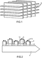
figure 1 est une vue en perspective d'un exemple de support de conversion catalytique selon l'invention, - la
figure 2 est une représentation schématique d'une vue en coupe d'une zone du dispositif de conversion catalytique de lafigure 1 . - Sur la
figure 1 , on peut voir un exemple de dispositif de conversion catalytique selon l'invention. Le dispositif est destiné à être disposé dans un conduit d'échappement et à être traversé par l'ensemble du débit d'échappement. Le dispositif comporte une pluralité de canaux 2 s'étendant dans la direction du flux de gaz d'échappement. Les gaz d'échappement entrent en contact avec la surface intérieure des canaux qui comportent des catalyseurs provoquant la conversion par exemple des NOx en N2 et du CO en CO2. Dans l'exemple représenté, les canaux ont une section transversale carrée mais ils pourraient présenter une section hexagonale de sorte à se rapprocher d'une structure en nid d'abeille. Plus généralement les canaux présentent une section polygonale. Par ailleurs toute autre forme permettant un bon contact entre les gaz et le dispositif convient. - En variante, le dispositif pourrait comporter des canaux dont l'une de leurs extrémités serait obturée. Par exemple un canal, comportant une extrémité longitudinale obturée, serait entouré par des canaux comportant une extrémité longitudinale opposée qui serait obturée afin de forcer le gaz à traverser la paroi des canaux, celles-ci étant poreuses. Cette structure a pour effet d'augmenter le temps de présence des gaz dans le dispositif et donc d'augmenter la quantité de polluants convertis.
- Sur la
figure 2 , on peut voir une vue en coupe de la paroi d'un canal 2 représentée schématiquement. - Le dispositif comporte un support 4 en matériau céramique tel qu'en mullite, cordiérite ou en céramique isotrope, le support forme le squelette du dispositif et comporte une pluralité de canaux parallèles les uns des autres. Le support est par exemple en matériau poreux avec une porosité comprise entre 30% et 70%.
- La céramique du support est choisie de sorte à être moins fragile que le SiC et à présenter avantageusement un coût de revient réduit par rapport au SiC. En outre, le matériau du support 4 est isolant électrique et thermique.
- La mullite et la cordiérite ont une conductivité thermique faible inférieure à 1 W.m.K.
- Le dispositif comporte une barrière thermique 6 sur le support 4, la barrière thermique 6 comportant un ou des matériaux isolants thermiques 6, ces matériaux isolants thermiques recouvrant au moins en partie le support 4. La barrière thermique 6 peut comporter une ou plusieurs couches de matériaux isolants thermiques.
- Le dispositif comporte également du SixCy poreux 8, avec 0<x<1 et 0<y<1, sur le matériau 6, une couche tampon 10 également appelée "wash-coat" sur le SixCy, et un ou plusieurs catalyseurs 12 sur la couche tampon 10 destinée à être en contact avec les gaz d'échappement.
- A des fins de simplicité, le SixCy sera désigné par la suite SiC.
- La porosité du SiC offre une surface développée importante ce qui permet soit de réduire la taille du support tout en conservant la même surface de SiC, soit d'augmenter la surface de SiC tout en conservant la même taille de support. En outre, le SiC poreux présente une structuration qui provoque une turbulence dans l'écoulement des gaz d'échappement ce qui améliore les contacts entre les gaz et les catalyseurs et facilites les réactions de conversion. La structuration du SiC poreux peut être suffisamment fine pour former une nanostructuration. Le SiC présente une porosité ouverte. Elle est comprise entre 55% et 70%, de préférence entre 60% et 65% déterminée par la méthode BET (théorie Brunauer, Emmet et Teller).
- Le ou les matériaux formant une barrière thermique 6, par exemple formés d'une ou plusieurs couches, sont choisis par exemple parmi le TiN, le YSZ, le AIZ (mélange de Al2O3 et de ZrO2 avec 5% et 30% de le ZrO2), TiAIN. Le ou les matériaux formant la barrière thermique présentent une conductivité thermique de préférence inférieure à 10 W/m.K. Le YSZ présente l'avantage de stopper les fissures au sein du matériau.
- Dans l'exemple représenté, la barrière thermique 6 est discontinue. Cette discontinuité peut provenir de la nature hétérogène du support. Un dispositif dans lequel la barrière thermique recouvrirait de manière continue le support ne sort pas du cadre de la présente invention.
- La couche tampon 10 est par exemple en CeO2, en ZrO2, en Al2O3, en BaCO3
- Le ou les catalyseurs 12 sont choisis par exemple parmi le Pt, Pd, Rh, Ag ou une combinaison de ceux-ci.
- De préférence, le ou les catalyseurs sont déposés sélectivement sur le SiC.
- Il est à noter que le Pt et le Pd servent préférentiellement à oxyder le CO en CO2 et le Rh sert préférentiellement à réduire les NOx en N2.
- A titre d'exemple le support a une épaisseur comprise entre 1 et 2mm, la couche de barrière thermique a une épaisseur comprise entre 20 µm à 250 µm, de préférence de l'ordre de 150 µm +/- 20 µm, la couche de SiC poreux a une épaisseur comprise entre 1 µm et 50 µm, de préférence comprise entre 5 à 10 µm et la couche de catalyseur qui peut être discontinue a une épaisseur comprise entre 4 et 12 nm.
- Le fonctionnement du dispositif de conversion catalytique va maintenant être décrit. Nous considérerons la conversion des NOx en N2.
- Par exemple, le dispositif est disposé dans un conduit d'échappement. Au démarrage du moteur à combustion, le dispositif en particulier les catalyseurs sont froids et ne sont donc pas activés, ils ne sont donc pas aptes à convertir les NOx en N2.
- Les gaz d'échappement chauds entrent en contact avec la surface du dispositif qui est froid, or, du fait de la bonne conductivité thermique du SiC, sa température augmente rapidement d'autant plus que la barrière thermique 6 limite les pertes thermiques du côté du support. Le SiC rayonne alors la chaleur vers les catalyseurs qui voient donc leur température augmentée rapidement et se trouvent donc activés rapidement. Ils sont prêts à convertir les NOx en N2 contenus dans les gaz d'échappement. La température d'activation est comprise environ entre 150°C et 600°C.
- Par ailleurs, le SiC poreux forme des réservoirs thermiques puisqu'il est isolé thermiquement du support, il forme donc une source de chaleur disponible pour les catalyseurs, les maintenant à une température proche de la température d'activation voire à la température d'activation. Ainsi les périodes transitoires d'activation des catalyseurs pendant les phases d'arrête/démarrage sont écourtées, assurant une dépollution sensiblement en continu des gaz d'échappement.
- Il en résulte une diminution, voire une suppression des NOx rejetés dans l'air.
- Un procédé de réalisation du dispositif selon l'invention va maintenant être décrit.
- Lors d'une première étape, un support en céramique par exemple en cordiérite ou en mullite est réalisé. Le support a par exemple la forme générale de la
figure 1 . - Lors d'une étape suivante, la barrière thermique 6 est formée sur le support.
- Lors d'une étape suivante, le SiC poreux est formé sur la barrière thermique. Avantageusement, une couche de SiC continue est tout d'abord déposée puis cette couche subit une étape de porosification. La couche de SiC est par exemple réalisée par enduction par exemple au moyen d'un polysiloxane, ensuite cette couche est chauffée par exemple entre 800°C et 1100°C ce qui rend la couche poreuse.
- Lors d'une étape suivante, le wash-coat est formé par exemple par imprégnation.
- Lors d'une étape suivante, le ou les catalyseurs sont déposés sur le wash-coat.
- De préférence, les catalyseurs sont déposés par dépôt chimique en phase vapeur ou CVD ("Chemical Vapor Déposition" en terminologie anglo-saxonne) et de préférence sélectivement sur le SiC.
- Le dépôt par CVD sur le SiC poreux présente l'avantage de réduire la quantité de catalyseur nécessaire, puisque le dépôt se fait sélectivement sur le SiC. En effet, le dépôt des catalyseurs sur le SiC se fait à température plus faible que sur la cordiérite ainsi en chauffant à une température suffisante le SiC pour assurer le dépôt de catalyseur sur le SiC uniquement, on obtient un dépôt de catalyseurs uniquement sur le SiC. Cette réduction de la quantité requise de catalyseur est d'autant plus avantageuse qu'il s'agit généralement de métaux précieux. La quantité de catalyseurs requise peut être réduite jusqu'à 50%. Le dépôt CVD a lieu par exemple à une température comprise entre 300°C et 400°C. Pour effectuer le dépôt CVD, l'objet sur lequel on souhaite effectuer le dépôt est chauffé par exemple par rayonnement et est ensuite mis en contact avec un mélange gazeux contenant un précurseur dudit métal à déposer ou des précurseurs desdits métaux à déposer et/ou de leurs alliages.
- Comme cela a été mentionné ci-dessus, le Pt et le Pd servent préférentiellement à l'oxydation du CO en CO2 et le Rh sert préférentiellement à la réduction des NOx en N2.
- De préférence, les dispositifs de conversion catalytique comportent à la fois des catalyseurs d'oxydation et des catalyseurs de réduction.
- De préférence, le dépôt de catalyseurs se fait en deux sous-étapes:
- Par exemple, lors d'une première sous-étape, on effectue le dépôt du ou des catalyseurs d'oxydation par exemple Pt et/ou Pd, et lors d'une deuxième sous-étape on effectue le dépôt du ou des catalyseurs de réduction par exemple du Rh. Cet ordre n'est pas limitatif et les catalyseurs de réduction pourraient être déposés avant les catalyseurs d'oxydation.
- Grâce à l'invention, les catalyseurs sont activés plus rapidement. Par exemple, en considérant le cycle de roulage normalisé NEDC (New European Driving Cycle) dans lequel les catalyseurs sont testés à froid, dans un dispositif de l'état de la technique, à partir d'un démarrage à froid les catalyseurs mettent environ 1 min à s'activer alors que dans un dispositif selon l'invention on réduit ce temps d'activation de 5 s à 20 s par cycle. En outre, les catalyseurs peuvent être activés en continu ou sensiblement en continu, la dépollution des gaz est donc améliorée. En outre, les turbulences provoquées par la nanostructuration des surfaces du dispositif de conversion favorisent encore davantage la conversion des polluants.
- Par exemple par rapport aux procédés de dépollution dans les moteurs diesel imposant l'injection de carburant pour les catalyseurs de réduction, le dispositif selon l'invention permet d'éviter cette injection et donc permet un gain sur la quantité de CO2 émise.
- En outre, la structure du dispositif selon l'invention permet de réduire la quantité de métaux précieux par dépôt CVD, ce qui a également pour effet de diminuer la température d'activation des catalyseurs de l'ordre de 15°C, ce qui permet d'obtenir une activation des catalyseurs encore plus rapide.
- Les catalyseurs déposés par CVD sur le SiC poreux présentent une structure facettée ce qui les rend plus actif, et une structure de taille contrôlée, par exemple comprise entre 4 à 12 nm. On obtient alors un rendement optimum entre la matière utilisée et la matière active.
- Un dispositif de conversion catalytique de CO uniquement ou de NOx uniquement ne sort pas du cadre de la présente invention.
- En outre, l'invention s'applique à la conversion catalytique de toute substance, le ou les catalyseurs étant choisis en fonction de la ou des substances à convertir.
- De plus l'invention ne se limite pas à des dispositifs de conversion de gaz d'échappement pour véhicule automobile mais à tout système produisant des gaz à traiter.
Claims (12)
- Dispositif de conversion catalytique comportant:- un support (4) en céramique muni d'au moins une surface- une barrière thermique (6) en au moins un matériau isolant thermique recouvrant au moins une partie de ladite surface du support (4),- du SiC poreux (8) recouvrant au moins en partie la barrière thermique (6) de sorte que le SiC (8) soit séparé du support par la barrière thermique (6), le SiC poreux (8) présentant une porosité comprise entre 55% et 70%, de préférence entre 60% et 65%.- un ou des catalyseurs (12) de conversion au moins sur le SiC poreux.
- Dispositif de conversion catalytique selon la revendication 1, dans lequel la barrière thermique comporte au moins une couche, ladite couche étant dans au moins l'un des matériaux choisis parmi le TiN, le YSZ, le AIZ, TiAIN.
- Dispositif de conversion catalytique selon la revendication 1 ou 2, dans lequel une couche tampon (10) est interposée entre le SiC (8) et le ou les catalyseurs (12).
- Dispositif de conversion catalytique selon la revendication 3, dans lequel le ou les matériaux de la couche tampon (10) sont choisis parmi CeO2, ZrO2, Al2O3, BaCO3.
- Dispositif de conversion catalytique selon l'une des revendications 1 à 4, dans lequel le ou les catalyseurs (12) sont choisis parmi le Pt, Pd, Rh, Ag, une combinaison de ces métaux.
- Dispositif de conversion catalytique selon l'une des revendications 1 à 5, dans lequel le support (4) est en cordiérite ou en mullite.
- Dispositif de conversion catalytique selon l'une des revendications 1 à 6, dans lequel le support (4) comporte des canaux (2), la surface du support (4) étant formée par la surface intérieure des canaux (2).
- Dispositif de traitement des gaz d'échappement d'un moteur à combustion interne comportant au moins un dispositif de conversion catalytique selon l'une des revendications 1 à 7.
- Procédé de réalisation d'un dispositif de conversion catalytique selon l'une des revendications 1 à 7, comportant les étapes:a) réalisation d'un support en céramique,b) formation d'une barrière thermique sur au moins une partie d'une surface dudit support,c) formation de SiC poreux sur une partie au moins de ladite barrière thermique,d) formation d'un ou de plusieurs catalyseurs de conversion sur le SiC.
- Procédé de réalisation selon la revendication 9, dans lequel l'étape d) a lieu par dépôt chimique en phase vapeur.
- Procédé de réalisation selon la revendication 9 ou 10, dans lequel lors de l'étape d) des catalyseurs d'oxydation et des catalyseurs de réduction sont déposés, et dans lequel les catalyseurs d'oxydation et les catalyseurs de réduction sont déposés lors de sous-étapes différentes.
- Procédé de réalisation selon l'une des revendications 9 à 11, dans lequel lors de l'étape b), une couche continue de SiC est formée puis ladite couche continue subit une étape de porosification, par exemple par chauffage entre 800°C et 1100°C.
Applications Claiming Priority (2)
| Application Number | Priority Date | Filing Date | Title |
|---|---|---|---|
| FR1459732A FR3026961B1 (fr) | 2014-10-10 | 2014-10-10 | Dispositif de conversion catalytique presentant un temps d'activation reduit |
| PCT/EP2015/073312 WO2016055596A1 (fr) | 2014-10-10 | 2015-10-08 | Dispositif de conversion catalytique presentant un temps d'activation reduit |
Publications (2)
| Publication Number | Publication Date |
|---|---|
| EP3204147A1 EP3204147A1 (fr) | 2017-08-16 |
| EP3204147B1 true EP3204147B1 (fr) | 2020-05-20 |
Family
ID=52102859
Family Applications (1)
| Application Number | Title | Priority Date | Filing Date |
|---|---|---|---|
| EP15780810.6A Active EP3204147B1 (fr) | 2014-10-10 | 2015-10-08 | Dispositif de conversion catalytique presentant un temps d'activation reduit |
Country Status (7)
| Country | Link |
|---|---|
| US (1) | US10408109B2 (fr) |
| EP (1) | EP3204147B1 (fr) |
| JP (1) | JP6618532B2 (fr) |
| KR (1) | KR20170066489A (fr) |
| CN (1) | CN106794422B (fr) |
| FR (1) | FR3026961B1 (fr) |
| WO (1) | WO2016055596A1 (fr) |
Families Citing this family (2)
| Publication number | Priority date | Publication date | Assignee | Title |
|---|---|---|---|---|
| CN112684832B (zh) * | 2019-10-17 | 2022-01-28 | 中国石油化工股份有限公司 | 克服碳化硅环状载体温度反应滞后的方法及设备 |
| KR102861679B1 (ko) * | 2022-05-12 | 2025-09-18 | 한국화학연구원 | 전기증착을 이용하여 산화촉매 모듈을 제조하는 방법 및 이에 따라 제조된 촉매 |
Family Cites Families (17)
| Publication number | Priority date | Publication date | Assignee | Title |
|---|---|---|---|---|
| CN1008513B (zh) * | 1984-04-13 | 1990-06-27 | 日本触媒化学株式会社 | 环氧乙烷生产用银催化剂及其制备方法 |
| JPS63248446A (ja) * | 1987-04-04 | 1988-10-14 | Mazda Motor Corp | 排気ガス浄化用触媒 |
| JPS6485604A (en) * | 1987-09-28 | 1989-03-30 | Yoshinobu Shimabukuro | Coral accessory and method for manufacturing the same |
| JPH01127045A (ja) * | 1987-11-13 | 1989-05-19 | Babcock Hitachi Kk | 燃焼用触媒 |
| JPH1085604A (ja) * | 1996-09-19 | 1998-04-07 | Denki Kagaku Kogyo Kk | 排気ガス浄化用触媒 |
| US5968456A (en) | 1997-05-09 | 1999-10-19 | Parise; Ronald J. | Thermoelectric catalytic power generator with preheat |
| US7250385B1 (en) | 1999-11-16 | 2007-07-31 | Ibiden Co., Ltd. | Catalyst and method for preparation thereof |
| EP1312776A3 (fr) * | 2001-11-16 | 2004-05-12 | Isuzu Motors Limited | Système pour la purification de gaz d'échappement |
| CN1320943C (zh) * | 2002-03-25 | 2007-06-13 | 揖斐电株式会社 | 废气净化用过滤器 |
| JP3899998B2 (ja) * | 2002-04-26 | 2007-03-28 | トヨタ自動車株式会社 | ハニカム構造体とその製造方法及びディーゼルパティキュレートフィルタ |
| US20040077494A1 (en) * | 2002-10-22 | 2004-04-22 | Labarge William J. | Method for depositing particles onto a catalytic support |
| US7799375B2 (en) * | 2004-06-30 | 2010-09-21 | Poco Graphite, Inc. | Process for the manufacturing of dense silicon carbide |
| JP4140636B2 (ja) * | 2006-04-10 | 2008-08-27 | いすゞ自動車株式会社 | 排気ガス浄化方法及び排気ガス浄化システム |
| JPWO2009133857A1 (ja) * | 2008-04-28 | 2011-09-01 | 住友大阪セメント株式会社 | 排ガス浄化フィルタ |
| WO2012077240A1 (fr) * | 2010-12-06 | 2012-06-14 | トヨタ自動車株式会社 | Dispositif de purification de gaz d'échappement destiné à un moteur à combustion interne |
| WO2015022399A2 (fr) * | 2013-08-14 | 2015-02-19 | Dinex A/S | Filtre à particules revêtu multi-couches |
| US9719176B2 (en) * | 2013-09-20 | 2017-08-01 | Hrl Laboratories, Llc | Thermal barrier materials and coatings with low heat capacity and low thermal conductivity |
-
2014
- 2014-10-10 FR FR1459732A patent/FR3026961B1/fr not_active Expired - Fee Related
-
2015
- 2015-10-08 JP JP2017518879A patent/JP6618532B2/ja not_active Expired - Fee Related
- 2015-10-08 KR KR1020177011485A patent/KR20170066489A/ko not_active Ceased
- 2015-10-08 US US15/517,560 patent/US10408109B2/en not_active Expired - Fee Related
- 2015-10-08 EP EP15780810.6A patent/EP3204147B1/fr active Active
- 2015-10-08 WO PCT/EP2015/073312 patent/WO2016055596A1/fr not_active Ceased
- 2015-10-08 CN CN201580054977.4A patent/CN106794422B/zh not_active Expired - Fee Related
Non-Patent Citations (1)
| Title |
|---|
| None * |
Also Published As
| Publication number | Publication date |
|---|---|
| WO2016055596A1 (fr) | 2016-04-14 |
| KR20170066489A (ko) | 2017-06-14 |
| JP6618532B2 (ja) | 2019-12-11 |
| EP3204147A1 (fr) | 2017-08-16 |
| CN106794422A (zh) | 2017-05-31 |
| US20180223714A1 (en) | 2018-08-09 |
| JP2017536975A (ja) | 2017-12-14 |
| FR3026961A1 (fr) | 2016-04-15 |
| US10408109B2 (en) | 2019-09-10 |
| CN106794422B (zh) | 2020-09-25 |
| FR3026961B1 (fr) | 2016-12-09 |
Similar Documents
| Publication | Publication Date | Title |
|---|---|---|
| JP5735983B2 (ja) | NOxトラップ | |
| EP0077711B1 (fr) | Pot catalytique pour l'épuration des gaz d'échappement d'un moteur à combustion interne | |
| EP0556129B1 (fr) | Tubulure d'échappement à paroi catalytique pour moteur à combustion interne | |
| EP3204147B1 (fr) | Dispositif de conversion catalytique presentant un temps d'activation reduit | |
| FR2928561A1 (fr) | Structure de filtration de gaz | |
| FR2907689A1 (fr) | Procede de traitement du methane imbrule par oxydation par plasma | |
| FR2728301A1 (fr) | Dispositif de traitement des gaz d'echappement d'un moteur a allumage commande comportant un corps catalyseur et un adsorbeur d'hydrocarbures disposes a l'interieur d'un collecteur d'echappement | |
| EP3197597B1 (fr) | Module catalytique presentant une efficacite amelioree au vieillissement | |
| WO2008020129A1 (fr) | Procédé d'imprégnation d'un corps poreux par une suspension et installation pour mettre en oeuvre un tel procédé. | |
| FR3057020A1 (fr) | Dispositif de post-traitement des gaz d’echappement d’un moteur thermique | |
| EP1381464B1 (fr) | Reacteur de catalyse comprenant un support de catalyseur avec des reseaux de canaux sécants | |
| EP1472442A1 (fr) | Procede de gestion de moyens de decolmatage d un filtre a particules. | |
| FR2728300A1 (fr) | Dispositif de traitement des gaz d'echappement d'un moteur a allumage par compression comportant un catalyseur et un adsorbeur d'oxydes d'azote places dans le collecteur d'echappement | |
| FR3066408B1 (fr) | Dispositif de post-traitement des gaz d’echappement d’un moteur thermique | |
| EP2959124B1 (fr) | Dispositif de traitement des gaz d'echappement par catalyse | |
| FR3061742A1 (fr) | Dispositif de post-traitement des gaz d’echappement d’un moteur thermique | |
| FR3062680A1 (fr) | Dispositif de post-traitement des gaz d’echappement d’un moteur thermique | |
| US20070009398A1 (en) | Waste gas cleaning system for an internal combustion engine | |
| JP2008069727A (ja) | 排ガス浄化装置、排ガス浄化触媒用担体基材及び排ガス浄化触媒 | |
| FR2914689A1 (fr) | Systeme de traitement des oxydes d'azote pour moteur a combustion interne | |
| WO2008078021A2 (fr) | Media filtrant pour dispositif de filtration des gaz d'echappement d'un moteur diesel, dispositif de filtration mettant en oeuvre un tel media, et ligne d'echappement des gaz d'un moteur a combustion interne mettant en oeuvre un tel dispositif | |
| WO2003099420A2 (fr) | Dispositif de filtration de gaz d'echappement | |
| FR2808840A1 (fr) | Procede de determination du point de montage d'un precatalyseur dans la tubulure d'echappement d'un moteur a combustion interne et installation d'epuration l'utilisant |
Legal Events
| Date | Code | Title | Description |
|---|---|---|---|
| STAA | Information on the status of an ep patent application or granted ep patent |
Free format text: STATUS: THE INTERNATIONAL PUBLICATION HAS BEEN MADE |
|
| PUAI | Public reference made under article 153(3) epc to a published international application that has entered the european phase |
Free format text: ORIGINAL CODE: 0009012 |
|
| STAA | Information on the status of an ep patent application or granted ep patent |
Free format text: STATUS: REQUEST FOR EXAMINATION WAS MADE |
|
| 17P | Request for examination filed |
Effective date: 20170414 |
|
| AK | Designated contracting states |
Kind code of ref document: A1 Designated state(s): AL AT BE BG CH CY CZ DE DK EE ES FI FR GB GR HR HU IE IS IT LI LT LU LV MC MK MT NL NO PL PT RO RS SE SI SK SM TR |
|
| AX | Request for extension of the european patent |
Extension state: BA ME |
|
| DAV | Request for validation of the european patent (deleted) | ||
| DAX | Request for extension of the european patent (deleted) | ||
| STAA | Information on the status of an ep patent application or granted ep patent |
Free format text: STATUS: EXAMINATION IS IN PROGRESS |
|
| 17Q | First examination report despatched |
Effective date: 20190521 |
|
| GRAP | Despatch of communication of intention to grant a patent |
Free format text: ORIGINAL CODE: EPIDOSNIGR1 |
|
| STAA | Information on the status of an ep patent application or granted ep patent |
Free format text: STATUS: GRANT OF PATENT IS INTENDED |
|
| RIC1 | Information provided on ipc code assigned before grant |
Ipc: B01J 23/48 20060101ALI20191202BHEP Ipc: B01J 35/04 20060101ALI20191202BHEP Ipc: F01N 3/28 20060101ALI20191202BHEP Ipc: B01J 27/224 20060101ALI20191202BHEP Ipc: B01J 23/44 20060101ALI20191202BHEP Ipc: B01J 23/63 20060101ALI20191202BHEP Ipc: B01D 53/94 20060101AFI20191202BHEP Ipc: B01J 23/40 20060101ALI20191202BHEP Ipc: B01J 37/02 20060101ALI20191202BHEP Ipc: B01J 23/42 20060101ALI20191202BHEP Ipc: B01J 23/46 20060101ALI20191202BHEP Ipc: F01N 3/10 20060101ALI20191202BHEP |
|
| INTG | Intention to grant announced |
Effective date: 20191220 |
|
| GRAS | Grant fee paid |
Free format text: ORIGINAL CODE: EPIDOSNIGR3 |
|
| GRAA | (expected) grant |
Free format text: ORIGINAL CODE: 0009210 |
|
| STAA | Information on the status of an ep patent application or granted ep patent |
Free format text: STATUS: THE PATENT HAS BEEN GRANTED |
|
| AK | Designated contracting states |
Kind code of ref document: B1 Designated state(s): AL AT BE BG CH CY CZ DE DK EE ES FI FR GB GR HR HU IE IS IT LI LT LU LV MC MK MT NL NO PL PT RO RS SE SI SK SM TR |
|
| REG | Reference to a national code |
Ref country code: GB Ref legal event code: FG4D Free format text: NOT ENGLISH |
|
| REG | Reference to a national code |
Ref country code: CH Ref legal event code: EP |
|
| REG | Reference to a national code |
Ref country code: DE Ref legal event code: R096 Ref document number: 602015053083 Country of ref document: DE |
|
| REG | Reference to a national code |
Ref country code: AT Ref legal event code: REF Ref document number: 1272238 Country of ref document: AT Kind code of ref document: T Effective date: 20200615 |
|
| REG | Reference to a national code |
Ref country code: LT Ref legal event code: MG4D |
|
| REG | Reference to a national code |
Ref country code: NL Ref legal event code: MP Effective date: 20200520 |
|
| PG25 | Lapsed in a contracting state [announced via postgrant information from national office to epo] |
Ref country code: NO Free format text: LAPSE BECAUSE OF FAILURE TO SUBMIT A TRANSLATION OF THE DESCRIPTION OR TO PAY THE FEE WITHIN THE PRESCRIBED TIME-LIMIT Effective date: 20200820 Ref country code: GR Free format text: LAPSE BECAUSE OF FAILURE TO SUBMIT A TRANSLATION OF THE DESCRIPTION OR TO PAY THE FEE WITHIN THE PRESCRIBED TIME-LIMIT Effective date: 20200821 Ref country code: FI Free format text: LAPSE BECAUSE OF FAILURE TO SUBMIT A TRANSLATION OF THE DESCRIPTION OR TO PAY THE FEE WITHIN THE PRESCRIBED TIME-LIMIT Effective date: 20200520 Ref country code: PT Free format text: LAPSE BECAUSE OF FAILURE TO SUBMIT A TRANSLATION OF THE DESCRIPTION OR TO PAY THE FEE WITHIN THE PRESCRIBED TIME-LIMIT Effective date: 20200921 Ref country code: LT Free format text: LAPSE BECAUSE OF FAILURE TO SUBMIT A TRANSLATION OF THE DESCRIPTION OR TO PAY THE FEE WITHIN THE PRESCRIBED TIME-LIMIT Effective date: 20200520 Ref country code: SE Free format text: LAPSE BECAUSE OF FAILURE TO SUBMIT A TRANSLATION OF THE DESCRIPTION OR TO PAY THE FEE WITHIN THE PRESCRIBED TIME-LIMIT Effective date: 20200520 Ref country code: IS Free format text: LAPSE BECAUSE OF FAILURE TO SUBMIT A TRANSLATION OF THE DESCRIPTION OR TO PAY THE FEE WITHIN THE PRESCRIBED TIME-LIMIT Effective date: 20200920 |
|
| PG25 | Lapsed in a contracting state [announced via postgrant information from national office to epo] |
Ref country code: HR Free format text: LAPSE BECAUSE OF FAILURE TO SUBMIT A TRANSLATION OF THE DESCRIPTION OR TO PAY THE FEE WITHIN THE PRESCRIBED TIME-LIMIT Effective date: 20200520 Ref country code: BG Free format text: LAPSE BECAUSE OF FAILURE TO SUBMIT A TRANSLATION OF THE DESCRIPTION OR TO PAY THE FEE WITHIN THE PRESCRIBED TIME-LIMIT Effective date: 20200820 Ref country code: RS Free format text: LAPSE BECAUSE OF FAILURE TO SUBMIT A TRANSLATION OF THE DESCRIPTION OR TO PAY THE FEE WITHIN THE PRESCRIBED TIME-LIMIT Effective date: 20200520 Ref country code: LV Free format text: LAPSE BECAUSE OF FAILURE TO SUBMIT A TRANSLATION OF THE DESCRIPTION OR TO PAY THE FEE WITHIN THE PRESCRIBED TIME-LIMIT Effective date: 20200520 |
|
| REG | Reference to a national code |
Ref country code: AT Ref legal event code: MK05 Ref document number: 1272238 Country of ref document: AT Kind code of ref document: T Effective date: 20200520 |
|
| PG25 | Lapsed in a contracting state [announced via postgrant information from national office to epo] |
Ref country code: AL Free format text: LAPSE BECAUSE OF FAILURE TO SUBMIT A TRANSLATION OF THE DESCRIPTION OR TO PAY THE FEE WITHIN THE PRESCRIBED TIME-LIMIT Effective date: 20200520 Ref country code: NL Free format text: LAPSE BECAUSE OF FAILURE TO SUBMIT A TRANSLATION OF THE DESCRIPTION OR TO PAY THE FEE WITHIN THE PRESCRIBED TIME-LIMIT Effective date: 20200520 |
|
| PG25 | Lapsed in a contracting state [announced via postgrant information from national office to epo] |
Ref country code: ES Free format text: LAPSE BECAUSE OF FAILURE TO SUBMIT A TRANSLATION OF THE DESCRIPTION OR TO PAY THE FEE WITHIN THE PRESCRIBED TIME-LIMIT Effective date: 20200520 Ref country code: AT Free format text: LAPSE BECAUSE OF FAILURE TO SUBMIT A TRANSLATION OF THE DESCRIPTION OR TO PAY THE FEE WITHIN THE PRESCRIBED TIME-LIMIT Effective date: 20200520 Ref country code: RO Free format text: LAPSE BECAUSE OF FAILURE TO SUBMIT A TRANSLATION OF THE DESCRIPTION OR TO PAY THE FEE WITHIN THE PRESCRIBED TIME-LIMIT Effective date: 20200520 Ref country code: CZ Free format text: LAPSE BECAUSE OF FAILURE TO SUBMIT A TRANSLATION OF THE DESCRIPTION OR TO PAY THE FEE WITHIN THE PRESCRIBED TIME-LIMIT Effective date: 20200520 Ref country code: IT Free format text: LAPSE BECAUSE OF FAILURE TO SUBMIT A TRANSLATION OF THE DESCRIPTION OR TO PAY THE FEE WITHIN THE PRESCRIBED TIME-LIMIT Effective date: 20200520 Ref country code: SM Free format text: LAPSE BECAUSE OF FAILURE TO SUBMIT A TRANSLATION OF THE DESCRIPTION OR TO PAY THE FEE WITHIN THE PRESCRIBED TIME-LIMIT Effective date: 20200520 Ref country code: EE Free format text: LAPSE BECAUSE OF FAILURE TO SUBMIT A TRANSLATION OF THE DESCRIPTION OR TO PAY THE FEE WITHIN THE PRESCRIBED TIME-LIMIT Effective date: 20200520 Ref country code: DK Free format text: LAPSE BECAUSE OF FAILURE TO SUBMIT A TRANSLATION OF THE DESCRIPTION OR TO PAY THE FEE WITHIN THE PRESCRIBED TIME-LIMIT Effective date: 20200520 |
|
| REG | Reference to a national code |
Ref country code: DE Ref legal event code: R097 Ref document number: 602015053083 Country of ref document: DE |
|
| PG25 | Lapsed in a contracting state [announced via postgrant information from national office to epo] |
Ref country code: SK Free format text: LAPSE BECAUSE OF FAILURE TO SUBMIT A TRANSLATION OF THE DESCRIPTION OR TO PAY THE FEE WITHIN THE PRESCRIBED TIME-LIMIT Effective date: 20200520 Ref country code: PL Free format text: LAPSE BECAUSE OF FAILURE TO SUBMIT A TRANSLATION OF THE DESCRIPTION OR TO PAY THE FEE WITHIN THE PRESCRIBED TIME-LIMIT Effective date: 20200520 |
|
| PLBE | No opposition filed within time limit |
Free format text: ORIGINAL CODE: 0009261 |
|
| STAA | Information on the status of an ep patent application or granted ep patent |
Free format text: STATUS: NO OPPOSITION FILED WITHIN TIME LIMIT |
|
| 26N | No opposition filed |
Effective date: 20210223 |
|
| PG25 | Lapsed in a contracting state [announced via postgrant information from national office to epo] |
Ref country code: SI Free format text: LAPSE BECAUSE OF FAILURE TO SUBMIT A TRANSLATION OF THE DESCRIPTION OR TO PAY THE FEE WITHIN THE PRESCRIBED TIME-LIMIT Effective date: 20200520 |
|
| REG | Reference to a national code |
Ref country code: CH Ref legal event code: PL |
|
| PG25 | Lapsed in a contracting state [announced via postgrant information from national office to epo] |
Ref country code: MC Free format text: LAPSE BECAUSE OF FAILURE TO SUBMIT A TRANSLATION OF THE DESCRIPTION OR TO PAY THE FEE WITHIN THE PRESCRIBED TIME-LIMIT Effective date: 20200520 Ref country code: LU Free format text: LAPSE BECAUSE OF NON-PAYMENT OF DUE FEES Effective date: 20201008 |
|
| REG | Reference to a national code |
Ref country code: BE Ref legal event code: MM Effective date: 20201031 |
|
| PG25 | Lapsed in a contracting state [announced via postgrant information from national office to epo] |
Ref country code: LI Free format text: LAPSE BECAUSE OF NON-PAYMENT OF DUE FEES Effective date: 20201031 Ref country code: CH Free format text: LAPSE BECAUSE OF NON-PAYMENT OF DUE FEES Effective date: 20201031 Ref country code: BE Free format text: LAPSE BECAUSE OF NON-PAYMENT OF DUE FEES Effective date: 20201031 |
|
| PG25 | Lapsed in a contracting state [announced via postgrant information from national office to epo] |
Ref country code: IE Free format text: LAPSE BECAUSE OF NON-PAYMENT OF DUE FEES Effective date: 20201008 |
|
| PGFP | Annual fee paid to national office [announced via postgrant information from national office to epo] |
Ref country code: GB Payment date: 20211020 Year of fee payment: 7 Ref country code: DE Payment date: 20211008 Year of fee payment: 7 |
|
| PGFP | Annual fee paid to national office [announced via postgrant information from national office to epo] |
Ref country code: FR Payment date: 20211029 Year of fee payment: 7 |
|
| PG25 | Lapsed in a contracting state [announced via postgrant information from national office to epo] |
Ref country code: TR Free format text: LAPSE BECAUSE OF FAILURE TO SUBMIT A TRANSLATION OF THE DESCRIPTION OR TO PAY THE FEE WITHIN THE PRESCRIBED TIME-LIMIT Effective date: 20200520 Ref country code: MT Free format text: LAPSE BECAUSE OF FAILURE TO SUBMIT A TRANSLATION OF THE DESCRIPTION OR TO PAY THE FEE WITHIN THE PRESCRIBED TIME-LIMIT Effective date: 20200520 Ref country code: CY Free format text: LAPSE BECAUSE OF FAILURE TO SUBMIT A TRANSLATION OF THE DESCRIPTION OR TO PAY THE FEE WITHIN THE PRESCRIBED TIME-LIMIT Effective date: 20200520 |
|
| PG25 | Lapsed in a contracting state [announced via postgrant information from national office to epo] |
Ref country code: MK Free format text: LAPSE BECAUSE OF FAILURE TO SUBMIT A TRANSLATION OF THE DESCRIPTION OR TO PAY THE FEE WITHIN THE PRESCRIBED TIME-LIMIT Effective date: 20200520 |
|
| REG | Reference to a national code |
Ref country code: DE Ref legal event code: R119 Ref document number: 602015053083 Country of ref document: DE |
|
| GBPC | Gb: european patent ceased through non-payment of renewal fee |
Effective date: 20221008 |
|
| PG25 | Lapsed in a contracting state [announced via postgrant information from national office to epo] |
Ref country code: FR Free format text: LAPSE BECAUSE OF NON-PAYMENT OF DUE FEES Effective date: 20221031 Ref country code: DE Free format text: LAPSE BECAUSE OF NON-PAYMENT OF DUE FEES Effective date: 20230503 |
|
| PG25 | Lapsed in a contracting state [announced via postgrant information from national office to epo] |
Ref country code: GB Free format text: LAPSE BECAUSE OF NON-PAYMENT OF DUE FEES Effective date: 20221008 |