EP3204239B1 - Fahrzeugluftreifen aufweisend eine gürtelbandage - Google Patents
Fahrzeugluftreifen aufweisend eine gürtelbandage Download PDFInfo
- Publication number
- EP3204239B1 EP3204239B1 EP15745212.9A EP15745212A EP3204239B1 EP 3204239 B1 EP3204239 B1 EP 3204239B1 EP 15745212 A EP15745212 A EP 15745212A EP 3204239 B1 EP3204239 B1 EP 3204239B1
- Authority
- EP
- European Patent Office
- Prior art keywords
- pneumatic vehicle
- dtex
- belt
- yarn
- vehicle tire
- Prior art date
- Legal status (The legal status is an assumption and is not a legal conclusion. Google has not performed a legal analysis and makes no representation as to the accuracy of the status listed.)
- Active
Links
Images
Classifications
-
- B—PERFORMING OPERATIONS; TRANSPORTING
- B60—VEHICLES IN GENERAL
- B60C—VEHICLE TYRES; TYRE INFLATION; TYRE CHANGING; CONNECTING VALVES TO INFLATABLE ELASTIC BODIES IN GENERAL; DEVICES OR ARRANGEMENTS RELATED TO TYRES
- B60C9/00—Reinforcements or ply arrangement of pneumatic tyres
- B60C9/18—Structure or arrangement of belts or breakers, crown-reinforcing or cushioning layers
- B60C9/20—Structure or arrangement of belts or breakers, crown-reinforcing or cushioning layers built-up from rubberised plies each having all cords arranged substantially parallel
- B60C9/22—Structure or arrangement of belts or breakers, crown-reinforcing or cushioning layers built-up from rubberised plies each having all cords arranged substantially parallel the plies being arranged with all cords disposed along the circumference of the tyre
-
- B—PERFORMING OPERATIONS; TRANSPORTING
- B60—VEHICLES IN GENERAL
- B60C—VEHICLE TYRES; TYRE INFLATION; TYRE CHANGING; CONNECTING VALVES TO INFLATABLE ELASTIC BODIES IN GENERAL; DEVICES OR ARRANGEMENTS RELATED TO TYRES
- B60C9/00—Reinforcements or ply arrangement of pneumatic tyres
- B60C9/0042—Reinforcements made of synthetic materials
-
- B—PERFORMING OPERATIONS; TRANSPORTING
- B60—VEHICLES IN GENERAL
- B60C—VEHICLE TYRES; TYRE INFLATION; TYRE CHANGING; CONNECTING VALVES TO INFLATABLE ELASTIC BODIES IN GENERAL; DEVICES OR ARRANGEMENTS RELATED TO TYRES
- B60C9/00—Reinforcements or ply arrangement of pneumatic tyres
- B60C9/005—Reinforcements made of different materials, e.g. hybrid or composite cords
-
- B—PERFORMING OPERATIONS; TRANSPORTING
- B60—VEHICLES IN GENERAL
- B60C—VEHICLE TYRES; TYRE INFLATION; TYRE CHANGING; CONNECTING VALVES TO INFLATABLE ELASTIC BODIES IN GENERAL; DEVICES OR ARRANGEMENTS RELATED TO TYRES
- B60C9/00—Reinforcements or ply arrangement of pneumatic tyres
- B60C2009/0071—Reinforcements or ply arrangement of pneumatic tyres characterised by special physical properties of the reinforcements
- B60C2009/0078—Modulus
-
- B—PERFORMING OPERATIONS; TRANSPORTING
- B60—VEHICLES IN GENERAL
- B60C—VEHICLE TYRES; TYRE INFLATION; TYRE CHANGING; CONNECTING VALVES TO INFLATABLE ELASTIC BODIES IN GENERAL; DEVICES OR ARRANGEMENTS RELATED TO TYRES
- B60C9/00—Reinforcements or ply arrangement of pneumatic tyres
- B60C9/18—Structure or arrangement of belts or breakers, crown-reinforcing or cushioning layers
- B60C9/20—Structure or arrangement of belts or breakers, crown-reinforcing or cushioning layers built-up from rubberised plies each having all cords arranged substantially parallel
- B60C9/22—Structure or arrangement of belts or breakers, crown-reinforcing or cushioning layers built-up from rubberised plies each having all cords arranged substantially parallel the plies being arranged with all cords disposed along the circumference of the tyre
- B60C2009/2223—Structure or arrangement of belts or breakers, crown-reinforcing or cushioning layers built-up from rubberised plies each having all cords arranged substantially parallel the plies being arranged with all cords disposed along the circumference of the tyre with an interrupted zero degree ply, e.g. using two or more portions for the same ply
-
- B—PERFORMING OPERATIONS; TRANSPORTING
- B60—VEHICLES IN GENERAL
- B60C—VEHICLE TYRES; TYRE INFLATION; TYRE CHANGING; CONNECTING VALVES TO INFLATABLE ELASTIC BODIES IN GENERAL; DEVICES OR ARRANGEMENTS RELATED TO TYRES
- B60C9/00—Reinforcements or ply arrangement of pneumatic tyres
- B60C9/18—Structure or arrangement of belts or breakers, crown-reinforcing or cushioning layers
- B60C9/20—Structure or arrangement of belts or breakers, crown-reinforcing or cushioning layers built-up from rubberised plies each having all cords arranged substantially parallel
- B60C9/22—Structure or arrangement of belts or breakers, crown-reinforcing or cushioning layers built-up from rubberised plies each having all cords arranged substantially parallel the plies being arranged with all cords disposed along the circumference of the tyre
- B60C2009/2252—Physical properties or dimension of the zero degree ply cords
- B60C2009/2257—Diameters of the cords; Linear density thereof
-
- B—PERFORMING OPERATIONS; TRANSPORTING
- B60—VEHICLES IN GENERAL
- B60C—VEHICLE TYRES; TYRE INFLATION; TYRE CHANGING; CONNECTING VALVES TO INFLATABLE ELASTIC BODIES IN GENERAL; DEVICES OR ARRANGEMENTS RELATED TO TYRES
- B60C9/00—Reinforcements or ply arrangement of pneumatic tyres
- B60C9/18—Structure or arrangement of belts or breakers, crown-reinforcing or cushioning layers
- B60C9/20—Structure or arrangement of belts or breakers, crown-reinforcing or cushioning layers built-up from rubberised plies each having all cords arranged substantially parallel
- B60C9/22—Structure or arrangement of belts or breakers, crown-reinforcing or cushioning layers built-up from rubberised plies each having all cords arranged substantially parallel the plies being arranged with all cords disposed along the circumference of the tyre
- B60C2009/2252—Physical properties or dimension of the zero degree ply cords
- B60C2009/2261—Modulus of the cords
Definitions
- the invention relates to a pneumatic vehicle tire with a carcass, a profiled tread, a belt and a single-layer or multi-layer belt bandage covering this belt with reinforcements running in the circumferential direction of the tire, with at least one bandage layer of the belt bandage in its axial extent having two side sections, each of which is axial Edge of the bandage layer, and comprises a middle section arranged between the two side sections, each side section having at least one hybrid strength member, the middle section having at least one strength member which has a lower modulus of elasticity than the hybrid strength members of the side sections, in each case measured in accordance with ASTM D885M when stretching of 3% and wherein the at least one hybrid strength member of each side section is a hybrid cord of at least two twisted yarns, at least one first yarn is a high modulus yarn and another yarn is a low modulus yarn, In order to prevent the tire from being raised by the centrifugal forces that occur during driving operation in pneumatic vehicle tires, in particular in high-speed use, it is known in
- the bandage is applied in the form of layers in the form of layers with reinforcements embedded in an unvulcanized rubber mixture, which are wound or wound on the belt.
- the reinforcement bars are embedded in rubber for such layers, in that a family of essentially parallel thread-like reinforcement bars, which are usually thermally and / or pretreated with impregnation in a manner known to the person skilled in the art with impregnation for better adhesion to the embedding rubber, have a calender in the longitudinal direction or passes through an extruder for coating with a rubber mixture.
- the strength members of the belt bandage should allow a sufficient elevation in the bombing and in the vulcanization form during tire manufacture, so that the tire can be shaped precisely, and they should ensure good high-speed suitability when the tire is finished in operation.
- the tire When the tire is bombed and vulcanized, the tire generally rises / stretches in the shoulder area by approx. 0.1% to 1.5% and in the middle area by approx. 2% to 4% compared to the unvulcanized blank when the blank is wound on a flat drum.
- the reinforcement should have an elongation at break sufficient for tire manufacture and should be able to be stretched in the central area of the pneumatic vehicle vehicle up to an expansion of approx. 3% to 4% with moderate effort and from a higher elongation only with a very high effort ,
- the DE 10 2008 037 615 A1 discloses a pneumatic vehicle tire with a belt bandage which, as a reinforcement, has a hybrid cord made of an aramid yarn and a polyamide yarn which are twisted together.
- the aramid yarn and the polyamide yarn each have a fineness of 250 dtex to 3000 dtex.
- the JP 2008 081076 A discloses a pneumatic vehicle tire with a belt bandage comprising a hybrid cord made of a polyketone yarn and a nylon yarn which are twisted together.
- a pneumatic vehicle tire is known whose belt bandage has cords made of PA 6.6 in its central section with a lower modulus of elasticity than the cords of the side sections, which are formed as a composite of aramid fibers and PA 6.6 fibers.
- the use of high-modulus material in the side areas enables good binding of the forces that occur there, whereas the pneumatic tire develops a round contour in the center area due to the low-modulus PA6.6 and thus has positive high-speed properties.
- Such a belt bandage thus has a positive effect on the high-speed strength and durability of the pneumatic vehicle tire.
- a pneumatic vehicle tire with a belt bandage with a bandage ply which has at least a first reinforcement and a second reinforcement.
- the first strength member is a hybrid cord composed of at least one high-modulus yarn and one low-modulus yarn.
- the second reinforcement has a lower modulus of elasticity than the first reinforcement.
- the ratio of the thread density of the hybrid cords to the thread density of the second reinforcement bars is 1: 1 in a central area and 2: 1 in a side area.
- the invention has for its object to provide a pneumatic vehicle tire with a belt bandage, which has reduced rolling resistance and good high-speed properties and which is also reliable to manufacture.
- the at least one hybrid strength member of each of the side sections has a fineness of at most 550 dtex, preferably of at most 500 dtex, particularly preferably of at most 460 dtex, and that the at least one strength member of the central section has a fineness of at most 1100 dtex , preferably of at most 600 dtex, particularly preferably of at most 500 dtex.
- the strength members in the side sections are hybrid cords made of at least one high-modulus yarn and at least one low-modulus yarn, which are twisted together.
- the high-modulus yarn is brought onto a helical path in order to enable it to constructively stretch in the hybrid cord and to increase the elongation at break increase.
- a reduction in the fineness of such hybrid cords to improve the rolling resistance generally leads to a lower structural elongation and thus to a reduction in the elongation at break.
- a “yarn” is a linear structure based on DIN 60900, which consists of individual filaments or fibers. The filaments or fibers of the yarn are preferably twisted together.
- a "cord” consists of two or more twisted yarns. The fineness of a cord is calculated as the sum of the fineness of the yarns of the cord.
- high modulus yarn means a yarn which consists of a high modulus material.
- low-modulus yarn means a yarn which consists of a low-modulus material.
- the low-modulus yarn and the high-modulus yarn are defined using the values in (mN / tex) described in Table 1 below.
- the force is determined, which must be applied to a yarn at 1% elongation and at 2% elongation, standardized to the yarn count in tex. It is determined according to ASTM D885.
- Table 1 Yarn / stretch 1% 2% Niedermodulig ⁇ 150 mN / tex ⁇ 200 mN / tex High modulus > 300 mN / tex > 500 mN / tex
- the essence of the invention is, in the two side areas of the belt bandage, in which the demands on the elongation at break of the reinforcement are less than in the middle area, thin hybrid cords, which are characterized by a very low fineness of at most 550 dtex, preferably of at most 500 dtex preferably of at most 460 dtex.
- the belt layer in the side sections can be made thinner, so that the weight of the tire and the build-up of heat when rolling off of the tire can be reduced. This reduces the tire's rolling resistance. It has been shown that a reduction in the fineness of the higher-modulus strength members of the side areas has a positive influence on the rolling resistance.
- Such thin cords can also be arranged at a higher density, which means that the belt bandage ensures very good high-speed durability.
- the lower-modulus strength member (s) of the central section ensure sufficient elevation in tire construction and in use. These reinforcements are also made with a small fineness, which has a positive effect on the rolling resistance.
- This provides a pneumatic vehicle tire with a belt bandage which, while still having good high-speed properties, has a reduced rolling resistance and which permits the different requirements for elevation in the case of bombing and in the form of vulcanization in the axial regions of the tire, and is therefore reliable to manufacture.
- the elongation at break of the hybrid strength members of the side sections is in a range from 4% to 7%, preferably in a range from 5% to 6%.
- the elongation at break of the reinforcement in the central area is at least 7%, preferably at least 8%.
- the elongation at break is determined according to ASTM D885.
- the high-modulus yarn advantageously consists of one of the materials mentioned below: aramid fiber, carbon fiber, glass fiber, basalt.
- the high-modulus yarn preferably consists of aramid fiber, preferably fibers of para-aramid or meta-aramid.
- the low-modulus yarn advantageously consists of a polyamide or a polyester.
- the polyamides (PA) can be the polyamides PA 4.6, PA 6, PA 6.6, PA 10.10, PA 11 and / or PA12, preferably PA 6.6 or PA 10.10.
- the polyesters can be the polyesters polyethylene naphthalate (PEN), polyethylene furanoate (PEF), polybutylene terephthalate (PBT), polybutylene naphtalate (PBN), polypropylene terephthalate (PPT), polypropylene naphthalate (PPN), polyethylene terephthalate (PET) and in particular thermoplastic polyester or crosslinked unsaturated polyesters.
- the individual yarns of the hybrid cords of the side sections each have a fineness of at most 320 dtex, preferably of at most 240 dtex. It has been shown that hybrid cords made from such thin yarns are outstandingly suitable for the side sections of a belt bandage and that such a belt bandage has a reduced rolling resistance.
- the hybrid cords of the side sections are formed from exactly two or from exactly three yarns. It is further expedient if the hybrid cords of the side sections are formed from exactly two yarns twisted together, the first yarn being an aramid yarn of the fineness 220 dtex and the second yarn either a PA 6.6 yarn of the fineness 235 dtex or a PET yarn of the fineness Is 238 dtex.
- the strength member of the central section is a yarn or a cord.
- the reinforcement of the central section consists of a polyamide (PA), preferably PA 6.6 or PA 10.10, or a polyester, preferably polyethylene terephthalate (PET).
- PA polyamide
- PET polyethylene terephthalate
- an adhesive impregnation e.g. to be provided with an RFL dip in a 1 or 2 bath process and stretched under the influence of temperature.
- each side section on its axial side of the tire covers at least the belt edge of the radially outermost belt layer and the axially outermost belt edge of the belt.
- the belt bandage is made in one layer.
- the belt bandage it is also appropriate for the belt bandage to have two or more bandage layers, at least one of the bandage layer comprising the center section and the two side sections.
- the belt bandage is particularly preferably a belt bandage of a motor vehicle.
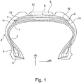
- the Figure 1 shows a radial cross section through a pneumatic vehicle tire for a passenger car.
- the essential components that make up the pneumatic vehicle tire shown are a largely air-impermeable inner layer 1, a carcass 2, which extends in a conventional manner from the zenith area of the pneumatic vehicle tire over the side walls 3 to the bead areas 4 and is anchored there by looping tensile bead cores 5, a profiled tread 6 located radially outside the carcass and one between the tread 6 and of the carcass 2 arranged belt 7 containing two reinforcement layers, which is covered radially on the outside with the belt bandage, which comprises a bandage layer 8.
- the bandage ply covers the belt edges 9 and contains reinforcements which are wound in parallel in the circumferential direction of the pneumatic vehicle tire along the axial width.
- the bandage layer 8 comprises two side sections 10, each of which comprises an axial edge 11 of the bandage layer 8, as well as a central section 12 arranged between the two side sections 10.
- Each of the two side sections 10 covers on its axial side of the tire at least the belt edge 9 of the radially outermost belt layer and the axially outermost belt edge 9 of the belt 7.
- the strength members of the two side sections 10 are formed as hybrid cords from a high-modulus yarn and a low-modulus yarn and have a cord fineness of at most 550 dtex, preferably at most 500 dtex, particularly preferably at most 460 dtex.
- the elongation at break of the hybrid cords is 5% to 6%.
- the strength member (s) of the middle section 12 are cords made of two twisted, low-modulus yarns and have a lower elastic modulus than the hybrid cords of the side sections 10, each measured according to ASTM D885M at an elongation of 3%.
- the cord fineness is at most 1100 dtex, preferably at most 600 dtex, particularly preferably at most 500 dtex.
- the elongation at break is at least 7%.
- the strength members of the belt bandage layer 8 are provided with an RFL dip and stretched under the influence of temperature.
- the high-modulus yarn of the hybrid cords of the side sections 10 is an aramid yarn of fineness 220 dtex and the low-modulus yarn is either a PA 6.6 yarn of fineness 235 dtex or a PET yarn of fineness 238 dtex.
- the one or more strength members of the central section 12 is made of two together Twisted yarns made of PA 6.6 with a fineness of 470 dtex or less or formed from two twisted yarns made of PET with a fineness of 550 dtex or less.
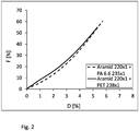
- the Fig.2 gives force-elongation curves, determined according to ASTM D885, of dipped hybrid cords for use in the side areas of the belt bandage as in Fig. 1 shown pneumatic vehicle tire.
- “Dipped” means: The cord was impregnated with a dip solution after twisting in a manner known to the person skilled in the art and was thus equipped in a rubber-friendly manner and stretched under the influence of temperature. The horizontal axis shows the strain D, the vertical axis the force F.
- the center cords have a lower modulus of elasticity at 3% elongation than the hybrid cords of the side sections.
- the use of high-modulus aramid material in the side areas ensures good binding of the forces occurring there, particularly in high-speed use, whereas the pneumatic tires in the center area develop a round contour due to the lower-modulus PA6.6 or PET and thus have positive high-speed properties.
Landscapes
- Engineering & Computer Science (AREA)
- Mechanical Engineering (AREA)
- Tires In General (AREA)
Description
- Die Erfindung betrifft einen Fahrzeugluftreifen mit einer Karkasse, einem profilierten Laufstreifen, einem Gürtel und einer diesen Gürtel bedeckenden ein- oder mehrlagigen Gürtelbandage mit in Umfangsrichtung des Reifens verlaufenden Festigkeitsträgern, wobei zumindest eine Bandagenlage der Gürtelbandage in ihrer axialen Ausdehnung zwei Seitenabschnitte, welche jeweils eine axiale Kante der Bandagenlage umfassen, sowie einen zwischen den beiden Seitenabschnitten angeordneten Mittenabschnitt umfasst, wobei jeder Seitenabschnitt zumindest einen Hybridfestigkeitsträger aufweist, wobei der Mittenabschnitt zumindest einen Festigkeitsträger aufweist, welcher einen geringeren Elastizitätsmodul aufweist als die Hybridfestigkeitsträger der Seitenabschnitte, jeweils gemessen gemäß ASTM D885M bei einer Dehnung von 3% und wobei der zumindest eine Hybridfestigkeitsträger jedes Seitenabschnittes ein Hybridcord aus wenigstens zwei miteinander vertwisteten Garnen ist, wobei wenigstens ein erstes Garn ein hochmoduliges Garn ist und wobei ein weiteres Garn ein niedermoduliges Garn ist,
Um bei Fahrzeugluftreifen, insbesondere beim Hochgeschwindigkeitseinsatz, eine Erhebung des Reifens durch die im Fahrbetrieb auftretenden Fliehkräfte zu verhindern, ist es bekannt, bei einem Fahrzeugluftreifen, der im Allgemeinen eine luftundurchlässige Innenschicht, eine Festigkeitsträger enthaltende Radialkarkasse, die vom Zenitbereich des Reifens über die Seitenwände bis in den Wulstbereich reicht und dort durch Umschlingen zugfester Wulstkerne verankert ist, einen radial außen befindlichen, Profilrillen aufweisenden Gummilaufstreifen und einen Gürtel zwischen dem Gummilaufstreifen und der Karkasse aufweist, eine Gürtelbandage vorzusehen. Die Gürtelbandage kann ein- oder mehrlagig ausgebildet sein, deckt zumindest die Gürtelränder ab und enthält parallel und im Wesentlichen in Umfangsrichtung verlaufende Festigkeitsträger, die in Gummi eingebettet sind. - Die Bandage wird bei der Reifenherstellung in Form von Lagen mit in eine unvulkanisierte Kautschukmischung eingebetteten Festigkeitsträgern aufgebracht, die auf den Gürtel gewickelt oder gespult werden. Die Festigkeitsträger werden für solche Lagen in Kautschuk eingebettet, indem eine Schar von im Wesentlichen parallel liegenden fadenförmigen Festigkeitsträgern, die in der Regel thermisch und/oder zur besseren Haftung am einbettenden Gummi in dem Fachmann bekannter Art mit einer Imprägnierung vorbehandelt sind, in Längsrichtung einen Kalander oder einen Extruder zur Ummantelung mit einer Kautschukmischung durchläuft.
- Die Festigkeitsträger der Gürtelbandage sollen bei der Reifenherstellung eine ausreichende Erhebung bei der Bombage sowie in der Vulkanisationsform zulassen, damit der Reifen präzise ausgeformt werden kann, und sie sollen nach der Fertigstellung des Reifens im Fahrbetrieb eine gute Hochgeschwindigkeitstauglichkeit gewährleisten.
- Bei der Bombage und Vulkanisation des Reifens erhebt/dehnt sich der Reifen in der Regel im Schulterbereich um ca. 0,1 % bis 1,5 % und im Mittenbereich um ca. 2 % bis 4 % im Vergleich zum unvulkanisierten Rohling, wenn der Rohling auf einer flachen Trommel gewickelt wird. Um diesen Anforderungen zu genügen, sollten die Festigkeitsträger eine für die Reifenherstellung ausreichende Bruchdehnung aufweisen und sich im Mittenbereich des Fahrzeugluftreifens bis zu einer Dehnung von ca. 3% bis 4% mit mäßigem Kraftaufwand und ab einer höheren Dehnung nur noch mit sehr hohem Kraftaufwand dehnen lassen.
- Die
DE 10 2008 037 615 A1 offenbart einen Fahrzeugluftreifen mit einer Gürtelbandage, welche als Festigkeitsträger einen Hybridcord aus einem Garn aus Aramid und einem Garn aus Polyamid, welche miteinander verdreht sind, aufweist. Das Aramid-Garn und das Polyamid-Garn weisen jeweils eine Feinheit von 250 dtex bis 3000 dtex auf. - Die
JP 2008 081076 A - Aus der
EP 1580030 B1 ist ein Fahrzeugluftreifen bekannt, dessen Gürtelbandage in ihrem Mittenabschnitt Corde aus PA 6.6 mit einen niedereren Elastizitätsmodul aufweisen als die Corde der Seitenabschnitte, welche als Verbund aus Aramidfasern und PA 6.6 Fasern ausgebildet sind. Im Fahrbetrieb, insbesondere im Hochgeschwindigkeitseinsatz, ermöglicht die Verwendung von hochmoduligerem Material in den Seitenbereichen eine gute Bindung der dort auftretenden Kräfte, wohingegen der Fahrzeugluftreifen durch das niedermoduligere PA6.6 im Mittenbereich eine runde Kontur entwickelt und somit positive Hochgeschwindigkeitseigenschaften aufweist. Eine solche Gürtelbandage wirkt sich somit positiv auf die Schnelllauffestigkeit und Dauerhaltbarkeit des Fahrzeugluftreifens aus. - Aus der
WO 2005/002884 A1 ist ein Fahrzeugluftreifen mit einer Gürtelbandage mit einer Bandagenlage bekannt welche zumindest einen ersten Festigkeitsträger und einen zweiten Festigkeitsträger aufweist. Der erste Festigkeitsträger ist dabei ein Hybridcord aus zumindest einem hochmoduligen Garn und einem niedermoduligen Garn. Der zweite Festigkeitsträger weist einen niedrigeren Elastizitätsmodul als der erste Festigkeitsträger auf. Das Verhältnis der Fadendichte der Hybridcorde zur Fadendichte der zweiten Festigkeitsträger beträgt in einem Mittenbereich 1:1 und in einem Seitenbereich 2:1. - Die Entwicklung geht dahin, den Rollwiderstand zu verbessern. Es ist dabei bekannt, dass dünne hochmodulige Materialien als Festigkeitsträger der Gürtelbandage zur Verbesserung des Rollwiderstands beitragen. Hierbei gibt es jedoch den Zielkonflikt, dass hochmodulige Materialien mit zu geringer Bruchdehnung den Bau auf einer Expansions-Trommel nicht ermöglichen.
- Der Erfindung liegt die Aufgabe zugrunde, einen Fahrzeugluftreifen mit einer Gürtelbandage bereitzustellen, der einen verringerten Rollwiderstand und gute Hochgeschwindigkeitseigenschaften aufweist und der zudem zuverlässig herzustellen ist.
- Gelöst wird die gestellte Aufgabe erfindungsgemäß dadurch, dass der zumindest eine Hybridfestigkeitsträger jedes der Seitenabschnitte eine Feinheit von höchstens 550 dtex, bevorzugt von höchstens 500 dtex, besonders bevorzugt von höchstens 460 dtex aufweisen und dass der zumindest eine Festigkeitsträger des Mittenabschnitts eine Feinheit von höchstens 1100 dtex, bevorzugt von höchstens 600 dtex, besonders bevorzugt von höchstens 500 dtex, aufweist.
- Im Rahmen der Erfindung hat sich herausgestellt, dass solche Festigkeitsträger mit einer derart geringen Feinheit sehr gut für die Gürtelbandage von Fahrzeugluftreifen geeignet sind.
- Die Festigkeitsträger in den Seitenabschnitten sind Hybridcorde aus wenigstens einem hochmoduligen Garn und wenistens einem niedermoduligen Garn, welche miteinander vertwistet sind. Hierdurch ist das hochmodulige Garn auf eine helikale Bahn gebracht, um ihm eine konstruktive Dehnung im Hybridcord zu ermöglichen und die Bruchdehnung zu erhöhen. Eine Verringerung der Feinheit solcher Hybridcorde zur Verbesserung des Rollwiderstandes führt im Allgemeinen jedoch zu einem geringeren konstruktiven Dehnungsvermögen und damit zu einer Verminderung der Bruchdehnung.
- Ein "Garn" ist im Rahmen der vorliegenden Erfindung in Anlehnung an die DIN 60900 ein linienförmiges Gebilde, das aus einzelnen Filamenten oder Fasern besteht. Bevorzugt sind die Filamente oder Fasern des Garns miteinander verdreht. Ein "Cord" besteht aus zwei oder mehr miteinander vertwisteten Garnen. Die Feinheit eines Cordes wird als die Summe der Feinheiten der Garne des Cordes berechnet.
- Mit dem Begriff "hochmoduliges Garn" ist ein Garn gemeint, welches aus einem hochmoduligen Material besteht. Mit dem Begriff "niedermoduliges Garn" ist ein Garn gemeint, welches aus einem niedermoduligen Material besteht. Dabei werden das niedermodulige Garn und das hochmodulige Garn anhand der in der nachfolgenden Tabelle 1 beschriebenen Werte in (mN/tex) definiert. Es ist die Kraft bestimmt, die jeweils auf ein Garn bei 1% Dehnung und bei 2% Dehnung aufgebracht werden muss, normiert auf die Garnfeinheit in tex. Ermittelt wird nach ASTM D885.
Tabelle 1 Garn/ Dehnung 1% 2% Niedermodulig < 150 mN/tex < 200 mN/tex Hochmodulig > 300 mN/tex > 500 mN/tex - Kern der Erfindung ist es, in den beiden Seitenbereichen der Gürtelbandage, in welchen die Anforderungen an die Bruchdehnung der Festigkeitsträger geringer sind als im Mittenbereich, dünne Hybridcorde, welche sich durch eine sehr geringe Feinheit von höchstens 550 dtex, bevorzugt von höchstens 500 dtex, besonders bevorzugt von höchstens 460 dtex, auszeichnen, einzusetzen. Hierdurch ist die Gürtellage in den Seitenabschnitten dünner ausführbar, sodass das Gewicht des Reifens und der Wärmeaufbau beim Abrollen des Reifens verringert werden. Dadurch wird der Rollwiderstand des Reifens reduziert. Es hat sich gezeigt, dass eine Reduktion der Feinheit der höhermoduligen Festigkeitsträger der Seitenbereiche den Rollwiderstand positiv beeinflusst. Auch lassen sich solch dünne Corde in höherer Dichte anordnen, wodurch die Gürtelbanddage eine sehr gute Hochgeschwindigkeitshaltbarkeit gewährleistet.
- Der oder die niedermoduligeren Festigkeitsträger des Mittenabschnitts gewährleisten die ausreichende Erhebung bei Reifenbau und im Einsatz. Auch diese Festigkeitsträger sind mit einer geringen Feinheit ausgeführt, was sich positiv auf den Rollwiderstand auswirkt.
- Der Einsatz von hochmoduligem Material in den Seitenabschnitten sowie der Einsatz von Festigkeitsträgern im Mittenabschnitt, deren Elastizitätsmodul geringer ist als das Elastizitätsmodul der Hybridcorde der Seitenabschnitte, gewährleistet weiterhin sehr gute Hochgeschwindigkeitseigenschaften des Reifens.
- Hierdurch ist ein Fahrzeugluftreifen mit einer Gürtelbandage zur Verfügung gestellt, der bei weiterhin guten Hochgeschwindigkeitseigenschaften einen verringerten Rollwiderstand aufweist und der die in den axialen Bereichen des Reifens unterschiedlichen Anforderungen an die Erhebung bei der Bombage und in der Vulkanisationsform zulassen und somit zuverlässig herzustellen ist.
- Für einen problemlosen Reifenbau ist es ausreichend, wenn die Bruchdehnung der Hybridfestigkeitsträger der Seitenabschnitte in einem Bereich von 4 % bis 7 %, bevorzugt in einem Bereich von 5 % bis 6 %, beträgt.
- Um die Erhebung des Reifens im Mittenbereich zu gewährleisten ist es vorteilhaft, wenn die Bruchdehnung des Festigkeitsträgers im Mittenbereich mindestens 7 %, bevorzugt mindestens 8 %, beträgt.
- Die Bruchdehnung wird ermittelt nach ASTM D885.
- Vorteilhafterweise besteht das hochmodulige Garn aus einem der nachfolgend genannten Materialien: Aramidfaser, Carbonfaser, Glasfaser, Basalt. Bevorzugt besteht das hochmodulige Garn aus Aramidfaser, wobei es sich bevorzugt um Fasern aus para-Aramid oder aus meta-Aramid handelt.
- Vorteilhafterweise besteht das niedermodulige Garn aus einem Polyamid oder einem Polyester. Bei den Polyamiden (PA) kann es sich um die Polyamide PA 4.6, PA 6, PA 6.6, PA 10.10, PA 11 und/oder PA12, bevorzugt um PA 6.6 oder PA 10.10, handeln. Bei den Polyestern kann es sich um die Polyester Polyethylennaphthalat (PEN), Polyethylenfuranoat (PEF), Polybutylenterephthalat (PBT), Polybutylennaphttalat (PBN), Polypropylenterephthalat (PPT), Polypropylennaphthalat (PPN), Polyethylenterephthalat (PET), insbesondere um thermoplastische Polyester und/oder vernetzte ungesättigte Polyester handeln.
- In einer bevorzugten Ausführungsform weisen die einzelnen Garne der Hybridcorde der Seitenabschnitte jeweils eine Feinheit von höchstens 320 dtex, bevorzugt von höchstens 240 dtex, auf. Es hat sich gezeigt, dass sich Hybridcorde aus solch dünnen Garnen hervorragend für die Seitenabschnitte einer Gürtelbandage eignen und dass eine solche Gürtelbandage einen verringerten Rollwiderstand aufweisen.
- Zweckmäßig ist es dabei, wenn die Hybridcorde der Seitenabschnitte aus genau zwei oder aus genau drei Garnen gebildet sind. Zweckmäßig ist es weiter, wenn die Hybridcorde der Seitenabschnitte aus genau zwei miteinander endverdrehten Garnen gebildet sind, wobei das erste Garn ein Aramidgarn der Feinheit 220 dtex und das zweite Garn entweder ein PA 6.6 -Garn der Feinheit 235 dtex oder ein PET-Garn der Feinheit 238 dtex ist.
- Zweckmäßig ist es, wenn der Festigkeitsträger des Mittenabschnitts ein Garn oder ein Cord ist.
- Vorteilhaft ist es, wenn der Festigkeitsträger des Mittenabschnitts aus einem Polyamid (PA), bevorzugt aus PA 6.6 oder PA 10.10, oder einem Polyester, bevorzugt aus Polyethylenterephthalat (PET), besteht.
- Um eine zuverlässige Haftung eines Festigkeitsträgers zum Gummi zu gewährleisten, ist es zweckmäßig, die Festigkeitsträger der Bandagenlage mit einer Haftimprägnierung, z.B. mit einem RFL-Dip im 1- oder 2-Bad-Verfahren, zu versehen und unter Temperatureinwirkung zu verstrecken.
- Als vorteilhaft hat es sich herausgestellt, wenn jeder Seitenabschnitt auf seiner axialen Seite des Reifens zumindest die Gürtelkante der radial äußersten Gürtellage sowie die axial äußerste Gürtelkante des Gürtels abdeckt.
- Zweckmäßig ist es, wenn die Gürtelbandage einlagig ausgeführt ist. Zeckmäßig ist es aber auch, wenn die Gürtelbandage zwei oder mehr Bandagenlagen aufweist, wobei zumindest eine der Bandagenlage den Mittenabschnitt und die zwei Seitenabschnitte umfasst.
- Besonders bevorzugt handelt es sich bei der Gürtelbandage um eine Gürtelbandage eines Personenkraftwagens.
- Weitere Merkmale, Vorteile und Einzelheiten der Erfindung werden nun anhand der schematischen Zeichnungen, die Ausführungsbeispiele darstellen, näher erläutert. Dabei zeigt die
-
Fig. 1 einen radialen Querschnitt durch einen erfindungsgemäßen Fahrzeugluftreifen; -
Fig. 2 eine Kraft-Dehnungskurve von im Rahmen der Erfindung geeigneten Festigkeitsträgercorden. - Die
Figur 1 zeigt einen radialen Querschnitt durch einen Fahrzeugluftreifen für einen Personenkraftwagen. Die wesentlichen Bauteile, aus welchen sich der dargestellte Fahrzeugluftreifen zusammensetzt, sind eine weitgehend luftundurchlässige Innenschicht 1, eine Karkasse 2, die in herkömmlicher Weise vom Zenitbereich des Fahrzeugluftreifens über die Seitenwände 3 bis in die Wulstbereiche 4 reicht und dort durch Umschlingen zugfester Wulstkerne 5 verankert ist, einen radial außerhalb der Karkasse befindlichen profilierten Laufstreifen 6 und einen zwischen dem Laufstreifen 6 und der Karkasse 2 angeordneten, zwei Festigkeitsträgerlagen beinhaltenden Gürtel 7, welcher radial außen mit der Gürtelbandage abgedeckt ist, welche eine Bandagenlage 8 umfasst. Die Bandagenlage deckt die Gürtelkanten 9 ab und beinhaltet Festigkeitsträger, die parallel in Umfangsrichtung des Fahrzeugluftreifens entlang der axialen Breite gewickelt sind. - Die Bandagenlage 8 umfasst in ihrer axialen Ausdehnung zwei Seitenabschnitte 10, welche jeweils eine axiale Kante 11 der Bandagenlage 8 umfassen, sowie einen zwischen den beiden Seitenabschnitten 10 angeordneten Mittenabschnitt 12 umfasst. Jeder der beiden Seitenabschnitt 10 deckt auf seiner axialen Seite des Reifens zumindest die Gürtelkante 9 der radial äußersten Gürtellage sowie die axial äußerste Gürtelkante 9 des Gürtels 7 ab.
- Die Festigkeitsträger der beiden Seitenabschnitte 10 sind als Hybridcorde aus einem hochmoduligen Garn und einem niedermoduligen Garn ausgebildet und weisen eine Cord-Feinheit von höchstens 550 dtex, bevorzugt von höchstens 500 dtex, besonders bevorzugt von höchstens 460 dtex auf. Die Bruchdehnung der Hybridcorde beträgt dabei 5% bis 6%. Der oder die Festigkeitsträger des Mittenabschnitts 12 sind Corde aus zwei vertwisteten niedermoduligen Garnen und weisen einen geringeren Elastizitätsmodul auf als die Hybridcorde der Seitenabschnitte 10, jeweils gemessen gemäß ASTM D885M bei einer Dehnung von 3%. Weiter beträgt die Cord-Feinheit höchstens 1100 dtex, bevorzugt höchstens 600 dtex, besonders bevorzugt höchstens 500 dtex. Die Bruchdehnung beträgt dabei mind. 7%. Die Festigkeitsträger der Gürtelbandagenlage 8 sind mit einem RFL-Dip versehen und unter Temperatureinwirkung verstreckt.
- In einer Ausführungsform der Erfindung ist das hochmodulige Garn der Hybridcorde der Seitenabschnitte 10 ein Aramidgarn der Feinheit 220 dtex und das niedermodulige Garn entweder ein PA 6.6 -Garn der Feinheit 235 dtex oder ein PET-Garn der Feinheit 238 dtex. Der oder die Festigkeitsträger des Mittenabschnitts 12 ist aus zwei miteinander vertwisteten Garnen aus PA 6.6 der Feinheit 470 dtex oder kleiner oder aus zwei miteinander vertwisteten Garnen aus PET der Feinheit 550 dtex oder kleiner gebildet.
- Die
Fig.2 gibt Kraft-Dehnungskurven, ermittelt gemäß ASTM D885, von gedippten Hybridkorden für den Einsatz in den Seitenbereichen der Gürtelbandage eines wie inFig. 1 gezeigten Fahrzeugluftreifens an. "Gedippt" bedeutet: Der Cord wurde in einer dem Fachmann bekannten Weise nach dem Twisten mit einer Dip-Lösung imprägniert und damit gummifreundlich ausgerüstet und unter Temperatureinwirkung verstreckt. Die horizontale Achse zeigt die Dehnung D, die vertikale Achse die Kraft F an. - Es sind Kraft-Dehnungskurven der zwei oben beschriebenen Hybridcorde der Konstruktionen Aramid 220x1 + PA 6.6 235x1 und Aramid 220x1 + PET 238x1 dargestellt. Es ist ersichtlich, dass beide Hybridcorde eine Bruchdehnung von 5 % bis 6 % aufweisen. In den Seitenbereichen ist somit eine ausreichende Erhebung beim Reifenbau gewährleistet.
- Weiter ist ersichtlich, dass die Mitten-Corde einen geringeren Elastizitätsmodul bei 3% Dehnung aufweisen als die Hybridcorde der Seitenabschnitte. Die Verwendung von hochmoduligem Aramid-Material in den Seitenbereichen gewährleistet eine gute Bindung der dort, insbesondere im Hochgeschwindigkeitseinsatz, auftretenden Kräfte, wohingegen der Fahrzeugluftreifen durch das niedermoduligere PA6.6 oder PET im Mittenbereich eine runde Kontur entwickelt und somit positive Hochgeschwindigkeitseigenschaften aufweist.
-
- 1
- Innenschicht
- 2
- Karkasse
- 3
- Seitenwand
- 4
- Wulstbereich
- 5
- Wulstkern
- 6
- Laufstreifen
- 7
- Gürtel
- 8
- Bandagenlage
- 9
- Gürtelkante
- 10
- Seitenabschnitt
- 11
- axiale Kante der Bandagenlage
- 12
- Mittenabschnitt
- aR
- axiale Richtung
- rR
- radiale Richtung
Claims (10)
- Fahrzeugluftreifen mit einer Karkasse (2), einem profilierten Laufstreifen (6), einem Gürtel (7) und einer diesen Gürtel (7) bedeckenden ein- oder mehrlagigen Gürtelbandage mit in Umfangsrichtung des Reifens verlaufenden Festigkeitsträgern,• wobei zumindest eine Bandagenlage (8) der Gürtelbandage in ihrer axialen Ausdehnung zwei Seitenabschnitte (10), welche jeweils eine axiale Kante (11) der Bandagenlage (8) umfassen, sowie einen zwischen den beiden Seitenabschnitten (10) angeordneten Mittenabschnitt (12) umfasst,• wobei jeder Seitenabschnitt (10) zumindest einen Hybridfestigkeitsträger aufweist,• wobei der Mittenabschnitt (12) zumindest einen Festigkeitsträger aufweist, welcher einen geringeren Elastizitätsmodul aufweist als die Hybridfestigkeitsträger der Seitenabschnitte (10), jeweils gemessen gemäß ASTM D885M bei einer Dehnung von 3% und• wobei der zumindest eine Hybridfestigkeitsträger jedes Seitenabschnittes (10) ein Hybridcord aus wenigstens zwei miteinander vertwisteten Garnen ist, wobei wenigstens ein erstes Garn ein hochmoduliges Garn ist und wobei ein weiteres Garn ein niedermoduliges Garn istdadurch gekennzeichnet, dass• der zumindest eine Hybridfestigkeitsträger jedes der Seitenabschnitte (10) eine Feinheit von höchstens 550 dtex, bevorzugt von höchstens 500 dtex, besonders bevorzugt von höchstens 460 dtex aufweisen und• dass der zumindest eine Festigkeitsträger des Mittenabschnitts (12) eine Feinheit von höchstens 1100 dtex, bevorzugt von höchstens 600 dtex, besonders bevorzugt von höchstens 500 dtex, aufweist.
- Fahrzeugluftreifen nach Anspruch 1, dadurch gekennzeichnet, dass die Bruchdehnung der Hybridfestigkeitsträger der Seitenabschnitte (10) in einem Bereich von 4 % bis 7 %, bevorzugt in einem Bereich von 5 % bis 6 %, liegt.
- Fahrzeugluftreifen nach Anspruch 1, dadurch gekennzeichnet, dass die Bruchdehnung des Festigkeitsträgers im Mittenbereich (12) mindestens 7 %, bevorzugt mindestens 8 %, liegt.
- Fahrzeugluftreifen nach Anspruch 2 oder 3, dadurch gekennzeichnet, dass das hochmodulige Garn aus Aramidfaser, Carbonfaser, Glasfaser oder Basalt besteht.
- Fahrzeugluftreifen nach einem oder mehreren der Ansprüche 2 bis 4, dadurch gekennzeichnet, dass das niedermodulige Garn das niedermodulige Garn aus einem Polyamid (PA), bevorzugt aus PA 6.6 oder PA 10.10, oder einem Polyester, bevorzugt aus Polyethylenterephthalat (PET), besteht.
- Fahrzeugluftreifen nach einem oder mehreren der Ansprüche 2 bis 5, dadurch gekennzeichnet, dass die einzelnen Garne der Hybridcorde der Seitenabschnitte (10) jeweils eine Feinheit von höchstens 320 dtex, bevorzugt von höchstens 240 dtex, aufweisen.
- Fahrzeugluftreifen nach einem oder mehreren der Ansprüche 1 bis 6, dadurch gekennzeichnet, dass der Festigkeitsträger des Mittenabschnitts (12) ein Garn oder ein Cord ist.
- Fahrzeugluftreifen nach einem oder mehreren der Ansprüche 1 bis 7, dadurch gekennzeichnet, dass der Festigkeitsträger des Mittenabschnitts (12) aus einem Polyamid (PA), bevorzugt aus PA 6.6 oder PA 10.10, oder einem Polyester, bevorzugt aus Polyethylenterephthalat (PET), besteht.
- Fahrzeugluftreifen nach einem oder mehreren der Ansprüche 1 bis 8, dadurch gekennzeichnet, dass jeder Seitenabschnitt (10) auf seiner axialen Seite des Reifens zumindest die Gürtelkante (9) der radial äußersten Gürtellage sowie die axial äußerste Gürtelkante (9) des Gürtels (7) abdeckt.
- Fahrzeugluftreifen nach einem oder mehreren der Ansprüche 1 bis 9, dadurch gekennzeichnet, dass es sich um einen Reifen für Personenkraftwagen handelt.
Applications Claiming Priority (2)
| Application Number | Priority Date | Filing Date | Title |
|---|---|---|---|
| DE102014220518.2A DE102014220518A1 (de) | 2014-10-09 | 2014-10-09 | Fahrzeugluftreifen aufweisend eine Gürtelbandage |
| PCT/EP2015/067899 WO2016055189A1 (de) | 2014-10-09 | 2015-08-04 | Fahrzeugluftreifen aufweisend eine gürtelbandage |
Publications (2)
| Publication Number | Publication Date |
|---|---|
| EP3204239A1 EP3204239A1 (de) | 2017-08-16 |
| EP3204239B1 true EP3204239B1 (de) | 2020-02-19 |
Family
ID=53773451
Family Applications (1)
| Application Number | Title | Priority Date | Filing Date |
|---|---|---|---|
| EP15745212.9A Active EP3204239B1 (de) | 2014-10-09 | 2015-08-04 | Fahrzeugluftreifen aufweisend eine gürtelbandage |
Country Status (5)
| Country | Link |
|---|---|
| US (1) | US20170246913A1 (de) |
| EP (1) | EP3204239B1 (de) |
| CN (1) | CN106715152B (de) |
| DE (1) | DE102014220518A1 (de) |
| WO (1) | WO2016055189A1 (de) |
Families Citing this family (6)
| Publication number | Priority date | Publication date | Assignee | Title |
|---|---|---|---|---|
| US11639565B2 (en) | 2016-09-29 | 2023-05-02 | Kolon Industries, Inc. | Hybrid tire cord and method for manufacturing the same |
| CN107364285A (zh) * | 2017-06-21 | 2017-11-21 | 太仓轮达汽车配件有限公司 | 一种高强度耐用型轮胎 |
| DE102018206562A1 (de) | 2018-04-27 | 2019-10-31 | Continental Reifen Deutschland Gmbh | Fahrzeugluftreifen |
| DE102019208984A1 (de) * | 2019-06-19 | 2020-12-24 | Continental Reifen Deutschland Gmbh | Fahrzeugreifen mit Gürtelbandage |
| WO2022074046A1 (en) * | 2020-10-07 | 2022-04-14 | Bridgestone Europe Nv/Sa | Sustainable hybrid cord for tyres |
| DE102021207531A1 (de) * | 2021-07-15 | 2023-01-19 | Continental Reifen Deutschland Gmbh | Duplexkord zur Verwendung als Festigkeitsträger in einer Gürtelbandage eines Fahrzeugluftreifens |
Family Cites Families (13)
| Publication number | Priority date | Publication date | Assignee | Title |
|---|---|---|---|---|
| AU625337B2 (en) * | 1989-05-31 | 1992-07-09 | Sp Reifenwerke Gmbh | Vehicle tyre |
| USH1333H (en) * | 1990-03-21 | 1994-07-05 | Helfer Farrel B | High strength reinforcement |
| DE4216695A1 (de) * | 1992-05-20 | 1993-12-02 | Sp Reifenwerke Gmbh | Fahrzeugreifen mit Verstärkungseinlagen |
| DE69509323T2 (de) * | 1994-08-23 | 1999-08-26 | Dunlop Gmbh | Fahrzeug-Luftreifen |
| EP0990539B1 (de) * | 1998-10-02 | 2006-07-26 | Société de Technologie Michelin | Reifen mit direkt auf den Textilkorden der radial äussersten Gürtelverstärkungslage aufgebrachter Laufflächenmischung |
| JP3993378B2 (ja) * | 2000-11-01 | 2007-10-17 | 住友ゴム工業株式会社 | 空気入りラジアルタイヤ |
| WO2005002884A1 (en) * | 2003-06-19 | 2005-01-13 | Pirelli Pneumatici S.P.A. | Tyre with improved belt structure |
| JP4723198B2 (ja) * | 2004-03-22 | 2011-07-13 | 住友ゴム工業株式会社 | 空気入りタイヤ |
| JP2008001248A (ja) * | 2006-06-23 | 2008-01-10 | Yokohama Rubber Co Ltd:The | 空気入りラジアルタイヤ |
| JP5007548B2 (ja) * | 2006-09-29 | 2012-08-22 | 横浜ゴム株式会社 | 空気入りラジアルタイヤ |
| JP4295795B2 (ja) * | 2007-12-07 | 2009-07-15 | 住友ゴム工業株式会社 | 空気入りタイヤ |
| DE102008037615A1 (de) * | 2008-12-01 | 2010-06-02 | Continental Reifen Deutschland Gmbh | Hybridkord zur Verwendung als Festigkeitsträger in einer Gürtelbandage eines Fahrzeugluftreifens |
| KR101411209B1 (ko) * | 2012-12-26 | 2014-06-23 | 한국타이어 주식회사 | 아라미드-폴리아미드 66 하이브리드 코드 및 그를 포함하는 연비 성능이 향상된 래디얼 타이어 |
-
2014
- 2014-10-09 DE DE102014220518.2A patent/DE102014220518A1/de not_active Withdrawn
-
2015
- 2015-08-04 EP EP15745212.9A patent/EP3204239B1/de active Active
- 2015-08-04 WO PCT/EP2015/067899 patent/WO2016055189A1/de not_active Ceased
- 2015-08-04 CN CN201580051749.1A patent/CN106715152B/zh active Active
- 2015-08-04 US US15/513,191 patent/US20170246913A1/en not_active Abandoned
Non-Patent Citations (1)
| Title |
|---|
| None * |
Also Published As
| Publication number | Publication date |
|---|---|
| CN106715152A (zh) | 2017-05-24 |
| EP3204239A1 (de) | 2017-08-16 |
| WO2016055189A1 (de) | 2016-04-14 |
| DE102014220518A1 (de) | 2016-04-14 |
| CN106715152B (zh) | 2019-05-21 |
| US20170246913A1 (en) | 2017-08-31 |
Similar Documents
| Publication | Publication Date | Title |
|---|---|---|
| EP1878591B1 (de) | Lage mit in eine Kautschukmischung eingebetteten Festigkeitsträgern und Fahrzeugluftreifen mit einer Gürtelbandage daraus | |
| EP3441237B1 (de) | Hybridkord zur verwendung als festigkeitsträger in einer gürtelbandage eines fahrzeugluftreifens | |
| WO2008145421A1 (de) | Hybridkord, insbesondere für eine gürtelbandage eines fahrzeugluftreifens | |
| EP1475248A1 (de) | Gürtelbandage mit Hybridkord und Reifen damit | |
| EP3204239A1 (de) | Fahrzeugluftreifen aufweisend eine gürtelbandage | |
| EP3724003B1 (de) | Festigkeitsträgerlage und fahrzeugluftreifen | |
| EP3031623B1 (de) | Hybridkord zur verwendung als festigkeitsträger in einer gürtelbandage eines fahrzeugluftreifens | |
| EP3073002B1 (de) | Festigkeitsträger für elastomere erzeugnisse, insbesondere für die gürtelbandage von fahrzeugluftreifen | |
| EP2114697B1 (de) | Festigkeitsträgerlage aus hybridcorden für elastomere erzeugnisse, insbesondere für die gürtelbandage von fahrzeugluftreifen | |
| EP2829419B1 (de) | Fahrzeugluftreifen | |
| EP2113397B1 (de) | Festigkeitsträgerlage aus Hybridcorden für elastomere Erzeugnisse, insbesondere für die Gürtelbandage von Fahrzeugluftreifen | |
| DE102017215655A1 (de) | Fahrzeugluftreifen aufweisend eine Gürtelbandage | |
| DE102014205700A1 (de) | Festigkeitsträgerlage für Fahrzeugluftreifen, insbesondere Karkassfestigkeitsträgerlage, aufweisend Hybridcorde | |
| EP2829420B1 (de) | Fahrzeugluftreifen | |
| DE102009044143A1 (de) | Gürtelbandage für einen Fahrzeugluftreifen und Fahrzeugluftreifen, enthaltend diese Gürtelbandage | |
| EP4177079B1 (de) | Festigkeitsträgerlage für elastomere erzeugnisse und fahrzeugluftreifen | |
| EP4433312B1 (de) | Fahrzeugluftreifen mit einer gürtelbandage | |
| EP3715144B1 (de) | Fahrzeugluftreifen aufweisend eine gürtelbandage mit einem hybridkord aufweisend pa 6.6 und pet | |
| DE102022211706A1 (de) | Verstärkungslage für einen Fahrzeugluftreifen aufweisend Monofilamente aus PA 4.6 | |
| DE102023202755A1 (de) | Verstärkungslage und Fahrzeugluftreifen aufweisend Monofilamentkorde aufweisend PA 4.6 | |
| DE102017217597A1 (de) | Festigkeitsträger für eine Festigkeitsträgerlage | |
| DE102017216883A1 (de) | Verstärkungscord zur Verwendung als Festigkeitsträger in einer Gürtelbandage und/oder Karkasse eines Fahrzeugluftreifens | |
| DE102009044216A1 (de) | Gürtelbandage für einen Fahrzeugluftreifen, enthaltend diese Gürtelbandage | |
| DE102010000563A1 (de) | Gürtelbandage für einen Fahrzeugluftreifen und Fahrzeugluftreifen, enthaltend diese Gürtelbandage | |
| DE102006023231A1 (de) | Elastomerprodukt |
Legal Events
| Date | Code | Title | Description |
|---|---|---|---|
| STAA | Information on the status of an ep patent application or granted ep patent |
Free format text: STATUS: THE INTERNATIONAL PUBLICATION HAS BEEN MADE |
|
| PUAI | Public reference made under article 153(3) epc to a published international application that has entered the european phase |
Free format text: ORIGINAL CODE: 0009012 |
|
| STAA | Information on the status of an ep patent application or granted ep patent |
Free format text: STATUS: REQUEST FOR EXAMINATION WAS MADE |
|
| 17P | Request for examination filed |
Effective date: 20170509 |
|
| AK | Designated contracting states |
Kind code of ref document: A1 Designated state(s): AL AT BE BG CH CY CZ DE DK EE ES FI FR GB GR HR HU IE IS IT LI LT LU LV MC MK MT NL NO PL PT RO RS SE SI SK SM TR |
|
| AX | Request for extension of the european patent |
Extension state: BA ME |
|
| DAV | Request for validation of the european patent (deleted) | ||
| DAX | Request for extension of the european patent (deleted) | ||
| GRAP | Despatch of communication of intention to grant a patent |
Free format text: ORIGINAL CODE: EPIDOSNIGR1 |
|
| RIC1 | Information provided on ipc code assigned before grant |
Ipc: B60C 9/22 20060101ALI20190917BHEP Ipc: B60C 9/00 20060101AFI20190917BHEP Ipc: B60C 9/18 20060101ALI20190917BHEP |
|
| STAA | Information on the status of an ep patent application or granted ep patent |
Free format text: STATUS: GRANT OF PATENT IS INTENDED |
|
| INTG | Intention to grant announced |
Effective date: 20191024 |
|
| GRAS | Grant fee paid |
Free format text: ORIGINAL CODE: EPIDOSNIGR3 |
|
| GRAA | (expected) grant |
Free format text: ORIGINAL CODE: 0009210 |
|
| STAA | Information on the status of an ep patent application or granted ep patent |
Free format text: STATUS: THE PATENT HAS BEEN GRANTED |
|
| AK | Designated contracting states |
Kind code of ref document: B1 Designated state(s): AL AT BE BG CH CY CZ DE DK EE ES FI FR GB GR HR HU IE IS IT LI LT LU LV MC MK MT NL NO PL PT RO RS SE SI SK SM TR |
|
| REG | Reference to a national code |
Ref country code: CH Ref legal event code: EP |
|
| REG | Reference to a national code |
Ref country code: DE Ref legal event code: R096 Ref document number: 502015011795 Country of ref document: DE |
|
| REG | Reference to a national code |
Ref country code: AT Ref legal event code: REF Ref document number: 1234525 Country of ref document: AT Kind code of ref document: T Effective date: 20200315 |
|
| REG | Reference to a national code |
Ref country code: IE Ref legal event code: FG4D Free format text: LANGUAGE OF EP DOCUMENT: GERMAN |
|
| REG | Reference to a national code |
Ref country code: NL Ref legal event code: MP Effective date: 20200219 |
|
| PG25 | Lapsed in a contracting state [announced via postgrant information from national office to epo] |
Ref country code: RS Free format text: LAPSE BECAUSE OF FAILURE TO SUBMIT A TRANSLATION OF THE DESCRIPTION OR TO PAY THE FEE WITHIN THE PRESCRIBED TIME-LIMIT Effective date: 20200219 Ref country code: FI Free format text: LAPSE BECAUSE OF FAILURE TO SUBMIT A TRANSLATION OF THE DESCRIPTION OR TO PAY THE FEE WITHIN THE PRESCRIBED TIME-LIMIT Effective date: 20200219 Ref country code: NO Free format text: LAPSE BECAUSE OF FAILURE TO SUBMIT A TRANSLATION OF THE DESCRIPTION OR TO PAY THE FEE WITHIN THE PRESCRIBED TIME-LIMIT Effective date: 20200519 |
|
| REG | Reference to a national code |
Ref country code: LT Ref legal event code: MG4D |
|
| PG25 | Lapsed in a contracting state [announced via postgrant information from national office to epo] |
Ref country code: HR Free format text: LAPSE BECAUSE OF FAILURE TO SUBMIT A TRANSLATION OF THE DESCRIPTION OR TO PAY THE FEE WITHIN THE PRESCRIBED TIME-LIMIT Effective date: 20200219 Ref country code: GR Free format text: LAPSE BECAUSE OF FAILURE TO SUBMIT A TRANSLATION OF THE DESCRIPTION OR TO PAY THE FEE WITHIN THE PRESCRIBED TIME-LIMIT Effective date: 20200520 Ref country code: BG Free format text: LAPSE BECAUSE OF FAILURE TO SUBMIT A TRANSLATION OF THE DESCRIPTION OR TO PAY THE FEE WITHIN THE PRESCRIBED TIME-LIMIT Effective date: 20200519 Ref country code: SE Free format text: LAPSE BECAUSE OF FAILURE TO SUBMIT A TRANSLATION OF THE DESCRIPTION OR TO PAY THE FEE WITHIN THE PRESCRIBED TIME-LIMIT Effective date: 20200219 Ref country code: LV Free format text: LAPSE BECAUSE OF FAILURE TO SUBMIT A TRANSLATION OF THE DESCRIPTION OR TO PAY THE FEE WITHIN THE PRESCRIBED TIME-LIMIT Effective date: 20200219 Ref country code: IS Free format text: LAPSE BECAUSE OF FAILURE TO SUBMIT A TRANSLATION OF THE DESCRIPTION OR TO PAY THE FEE WITHIN THE PRESCRIBED TIME-LIMIT Effective date: 20200619 |
|
| PG25 | Lapsed in a contracting state [announced via postgrant information from national office to epo] |
Ref country code: NL Free format text: LAPSE BECAUSE OF FAILURE TO SUBMIT A TRANSLATION OF THE DESCRIPTION OR TO PAY THE FEE WITHIN THE PRESCRIBED TIME-LIMIT Effective date: 20200219 |
|
| PG25 | Lapsed in a contracting state [announced via postgrant information from national office to epo] |
Ref country code: SK Free format text: LAPSE BECAUSE OF FAILURE TO SUBMIT A TRANSLATION OF THE DESCRIPTION OR TO PAY THE FEE WITHIN THE PRESCRIBED TIME-LIMIT Effective date: 20200219 Ref country code: PT Free format text: LAPSE BECAUSE OF FAILURE TO SUBMIT A TRANSLATION OF THE DESCRIPTION OR TO PAY THE FEE WITHIN THE PRESCRIBED TIME-LIMIT Effective date: 20200712 Ref country code: RO Free format text: LAPSE BECAUSE OF FAILURE TO SUBMIT A TRANSLATION OF THE DESCRIPTION OR TO PAY THE FEE WITHIN THE PRESCRIBED TIME-LIMIT Effective date: 20200219 Ref country code: CZ Free format text: LAPSE BECAUSE OF FAILURE TO SUBMIT A TRANSLATION OF THE DESCRIPTION OR TO PAY THE FEE WITHIN THE PRESCRIBED TIME-LIMIT Effective date: 20200219 Ref country code: EE Free format text: LAPSE BECAUSE OF FAILURE TO SUBMIT A TRANSLATION OF THE DESCRIPTION OR TO PAY THE FEE WITHIN THE PRESCRIBED TIME-LIMIT Effective date: 20200219 Ref country code: SM Free format text: LAPSE BECAUSE OF FAILURE TO SUBMIT A TRANSLATION OF THE DESCRIPTION OR TO PAY THE FEE WITHIN THE PRESCRIBED TIME-LIMIT Effective date: 20200219 Ref country code: DK Free format text: LAPSE BECAUSE OF FAILURE TO SUBMIT A TRANSLATION OF THE DESCRIPTION OR TO PAY THE FEE WITHIN THE PRESCRIBED TIME-LIMIT Effective date: 20200219 Ref country code: LT Free format text: LAPSE BECAUSE OF FAILURE TO SUBMIT A TRANSLATION OF THE DESCRIPTION OR TO PAY THE FEE WITHIN THE PRESCRIBED TIME-LIMIT Effective date: 20200219 Ref country code: ES Free format text: LAPSE BECAUSE OF FAILURE TO SUBMIT A TRANSLATION OF THE DESCRIPTION OR TO PAY THE FEE WITHIN THE PRESCRIBED TIME-LIMIT Effective date: 20200219 |
|
| REG | Reference to a national code |
Ref country code: DE Ref legal event code: R097 Ref document number: 502015011795 Country of ref document: DE |
|
| RAP2 | Party data changed (patent owner data changed or rights of a patent transferred) |
Owner name: CONTINENTAL REIFEN DEUTSCHLAND GMBH |
|
| PLBE | No opposition filed within time limit |
Free format text: ORIGINAL CODE: 0009261 |
|
| STAA | Information on the status of an ep patent application or granted ep patent |
Free format text: STATUS: NO OPPOSITION FILED WITHIN TIME LIMIT |
|
| 26N | No opposition filed |
Effective date: 20201120 |
|
| PG25 | Lapsed in a contracting state [announced via postgrant information from national office to epo] |
Ref country code: IT Free format text: LAPSE BECAUSE OF FAILURE TO SUBMIT A TRANSLATION OF THE DESCRIPTION OR TO PAY THE FEE WITHIN THE PRESCRIBED TIME-LIMIT Effective date: 20200219 |
|
| PG25 | Lapsed in a contracting state [announced via postgrant information from national office to epo] |
Ref country code: PL Free format text: LAPSE BECAUSE OF FAILURE TO SUBMIT A TRANSLATION OF THE DESCRIPTION OR TO PAY THE FEE WITHIN THE PRESCRIBED TIME-LIMIT Effective date: 20200219 Ref country code: SI Free format text: LAPSE BECAUSE OF FAILURE TO SUBMIT A TRANSLATION OF THE DESCRIPTION OR TO PAY THE FEE WITHIN THE PRESCRIBED TIME-LIMIT Effective date: 20200219 |
|
| PG25 | Lapsed in a contracting state [announced via postgrant information from national office to epo] |
Ref country code: MC Free format text: LAPSE BECAUSE OF FAILURE TO SUBMIT A TRANSLATION OF THE DESCRIPTION OR TO PAY THE FEE WITHIN THE PRESCRIBED TIME-LIMIT Effective date: 20200219 |
|
| REG | Reference to a national code |
Ref country code: CH Ref legal event code: PL |
|
| GBPC | Gb: european patent ceased through non-payment of renewal fee |
Effective date: 20200804 |
|
| PG25 | Lapsed in a contracting state [announced via postgrant information from national office to epo] |
Ref country code: LI Free format text: LAPSE BECAUSE OF NON-PAYMENT OF DUE FEES Effective date: 20200831 Ref country code: LU Free format text: LAPSE BECAUSE OF NON-PAYMENT OF DUE FEES Effective date: 20200804 Ref country code: CH Free format text: LAPSE BECAUSE OF NON-PAYMENT OF DUE FEES Effective date: 20200831 |
|
| REG | Reference to a national code |
Ref country code: BE Ref legal event code: MM Effective date: 20200831 |
|
| PG25 | Lapsed in a contracting state [announced via postgrant information from national office to epo] |
Ref country code: IE Free format text: LAPSE BECAUSE OF NON-PAYMENT OF DUE FEES Effective date: 20200804 Ref country code: BE Free format text: LAPSE BECAUSE OF NON-PAYMENT OF DUE FEES Effective date: 20200831 Ref country code: GB Free format text: LAPSE BECAUSE OF NON-PAYMENT OF DUE FEES Effective date: 20200804 |
|
| REG | Reference to a national code |
Ref country code: AT Ref legal event code: MM01 Ref document number: 1234525 Country of ref document: AT Kind code of ref document: T Effective date: 20200804 |
|
| PG25 | Lapsed in a contracting state [announced via postgrant information from national office to epo] |
Ref country code: AT Free format text: LAPSE BECAUSE OF NON-PAYMENT OF DUE FEES Effective date: 20200804 |
|
| PG25 | Lapsed in a contracting state [announced via postgrant information from national office to epo] |
Ref country code: TR Free format text: LAPSE BECAUSE OF FAILURE TO SUBMIT A TRANSLATION OF THE DESCRIPTION OR TO PAY THE FEE WITHIN THE PRESCRIBED TIME-LIMIT Effective date: 20200219 Ref country code: MT Free format text: LAPSE BECAUSE OF FAILURE TO SUBMIT A TRANSLATION OF THE DESCRIPTION OR TO PAY THE FEE WITHIN THE PRESCRIBED TIME-LIMIT Effective date: 20200219 Ref country code: CY Free format text: LAPSE BECAUSE OF FAILURE TO SUBMIT A TRANSLATION OF THE DESCRIPTION OR TO PAY THE FEE WITHIN THE PRESCRIBED TIME-LIMIT Effective date: 20200219 |
|
| PG25 | Lapsed in a contracting state [announced via postgrant information from national office to epo] |
Ref country code: MK Free format text: LAPSE BECAUSE OF FAILURE TO SUBMIT A TRANSLATION OF THE DESCRIPTION OR TO PAY THE FEE WITHIN THE PRESCRIBED TIME-LIMIT Effective date: 20200219 Ref country code: AL Free format text: LAPSE BECAUSE OF FAILURE TO SUBMIT A TRANSLATION OF THE DESCRIPTION OR TO PAY THE FEE WITHIN THE PRESCRIBED TIME-LIMIT Effective date: 20200219 |
|
| REG | Reference to a national code |
Ref country code: DE Ref legal event code: R081 Ref document number: 502015011795 Country of ref document: DE Owner name: CONTINENTAL REIFEN DEUTSCHLAND GMBH, DE Free format text: FORMER OWNER: CONTINENTAL REIFEN DEUTSCHLAND GMBH, 30165 HANNOVER, DE |
|
| PGFP | Annual fee paid to national office [announced via postgrant information from national office to epo] |
Ref country code: DE Payment date: 20250831 Year of fee payment: 11 |
|
| PGFP | Annual fee paid to national office [announced via postgrant information from national office to epo] |
Ref country code: FR Payment date: 20250829 Year of fee payment: 11 |