EP3204561B1 - Vanne de remplissage - Google Patents
Vanne de remplissage Download PDFInfo
- Publication number
- EP3204561B1 EP3204561B1 EP15775448.2A EP15775448A EP3204561B1 EP 3204561 B1 EP3204561 B1 EP 3204561B1 EP 15775448 A EP15775448 A EP 15775448A EP 3204561 B1 EP3204561 B1 EP 3204561B1
- Authority
- EP
- European Patent Office
- Prior art keywords
- flow
- membrane
- opening
- fill valve
- valve according
- Prior art date
- Legal status (The legal status is an assumption and is not a legal conclusion. Google has not performed a legal analysis and makes no representation as to the accuracy of the status listed.)
- Active
Links
Images


Classifications
-
- E—FIXED CONSTRUCTIONS
- E03—WATER SUPPLY; SEWERAGE
- E03D—WATER-CLOSETS OR URINALS WITH FLUSHING DEVICES; FLUSHING VALVES THEREFOR
- E03D1/00—Water flushing devices with cisterns ; Setting up a range of flushing devices or water-closets; Combinations of several flushing devices
- E03D1/30—Valves for high or low level cisterns; Their arrangement ; Flushing mechanisms in the cistern, optionally with provisions for a pre-or a post- flushing and for cutting off the flushing mechanism in case of leakage
- E03D1/32—Arrangement of inlet valves
-
- F—MECHANICAL ENGINEERING; LIGHTING; HEATING; WEAPONS; BLASTING
- F16—ENGINEERING ELEMENTS AND UNITS; GENERAL MEASURES FOR PRODUCING AND MAINTAINING EFFECTIVE FUNCTIONING OF MACHINES OR INSTALLATIONS; THERMAL INSULATION IN GENERAL
- F16K—VALVES; TAPS; COCKS; ACTUATING-FLOATS; DEVICES FOR VENTING OR AERATING
- F16K31/00—Actuating devices; Operating means; Releasing devices
- F16K31/12—Actuating devices; Operating means; Releasing devices actuated by fluid
- F16K31/18—Actuating devices; Operating means; Releasing devices actuated by fluid actuated by a float
- F16K31/34—Actuating devices; Operating means; Releasing devices actuated by fluid actuated by a float acting on pilot valve controlling the cut-off apparatus
-
- F—MECHANICAL ENGINEERING; LIGHTING; HEATING; WEAPONS; BLASTING
- F16—ENGINEERING ELEMENTS AND UNITS; GENERAL MEASURES FOR PRODUCING AND MAINTAINING EFFECTIVE FUNCTIONING OF MACHINES OR INSTALLATIONS; THERMAL INSULATION IN GENERAL
- F16K—VALVES; TAPS; COCKS; ACTUATING-FLOATS; DEVICES FOR VENTING OR AERATING
- F16K47/00—Means in valves for absorbing fluid energy
- F16K47/02—Means in valves for absorbing fluid energy for preventing water-hammer or noise
-
- G—PHYSICS
- G05—CONTROLLING; REGULATING
- G05D—SYSTEMS FOR CONTROLLING OR REGULATING NON-ELECTRIC VARIABLES
- G05D7/00—Control of flow
- G05D7/01—Control of flow without auxiliary power
- G05D7/0106—Control of flow without auxiliary power the sensing element being a flexible member, e.g. bellows, diaphragm, capsule
- G05D7/012—Control of flow without auxiliary power the sensing element being a flexible member, e.g. bellows, diaphragm, capsule the sensing element being deformable and acting as a valve
Definitions
- the invention relates to a filling valve for filling a cistern with a liquid, in particular with water, wherein the filling valve has an inlet with a flow regulator having a throttle device for reducing the pressure of the liquid flowing in the direction of flow.
- a problem with such filling valves is that the inflow of liquid through the throttle device is connected to the filling valve with a slightly annoying perceived noise.
- a generic, complex constructed filling valve with flow regulator is in the EP 1 862 604 A2 described.
- a flow regulator disclosed has a housing in which a housing core is arranged. Between housing and housing core, a flow cross-section is provided. On the housing, a sealing lip is provided to the housing core robend. With increasing pressure, the sealing lip approaches the housing core to reduce the flow cross-section.
- FR 2 369 615 A1 discloses a flow regulator with an inflow and an outflow opening. The flow regulator has a membrane which, with increasing flow pressure of the Outflow increasingly approaches the increasing closure of the outflow opening.
- WO 2013/178912 A1 discloses a valve that transmits fluid flow only in a forward direction and blocks in an opposite reverse direction.
- a membrane is provided, which rests on one side of a flow opening. In a fluid flow in the forward direction, the membrane is lifted from the passage opening to expose a flow cross-section, with a fluid flow in the reverse direction, the membrane is sealingly pressed against the opening.
- WO 2007/105020 A1 discloses a valve that allows fluid flow substantially only in a flow direction and substantially blocks in a reverse direction. In this case, a membrane is provided, which rests on a surface portion in which a flow opening is provided. In the flow direction, the membrane is lifted off the surface to release a flow area.
- a membrane is provided which abuts on one side of a flow opening and which is lifted at a fluid flow in the forward direction of the flow opening for releasing a flow cross-section, whereas it is pressed against the opening in a fluid flow in the reverse direction.
- one Passage valve disclosed in which a damping element is provided for reducing the flow noise through the valve, wherein the damping element for this purpose has a blocking surface which blocks a flow cross-section of the valve in sections and extending from the arms away in the flow direction.
- WO 2010/098750 A1 discloses a check valve which blocks a flow of fluid as soon as the fluid pressure exceeds a predetermined threshold. For this purpose, the check valve to a membrane which is deformed in response to the fluid pressure and depending on their deformation on a housing to the plant to block the fluid flow.
- An object of the invention is to provide a generic filling valve in which the flow noise during filling are further reduced.
- the flow regulator is designed as a flow control to maintain a flow constant as a function of the flow pressure of the liquid at the inlet to reduce flow noise when filling the cistern
- the flow control has a extending over the flow cross-section of the inlet support with at least one primary opening by means of an upstream membrane with increasing flow pressure progressively sealingly coverable or arranged with decreasing the same progressively releasable
- the flow control has at least one secondary opening which is permanently open, which ensures that a part of the liquid flow control in the case of a complete sealing overlap flows through the at least one primary opening as long as the Flow pressure of the liquid at the at least one secondary opening is greater than zero
- the at least one secondary opening is bounded by an inner wall, which is roughened to reduce noise emission during the flow and / or formed dotted.
- the noise when filling the water box through the filling valve depends, among other things, on the volume flow and its changes.
- the noise changes with the change in the volume flow.
- changes in the noise can be easily perceived as corresponding disturbing.
- the volume flow increases with increasing pressure.
- the throttle according to the invention on the other hand, owing to the constant volume flow, no increased flow noise occurs even at higher pressures.
- the volume flow constancy can be understood in each case so that the volume flow remains approximately constant and thus may have deviations upwards and / or downwards. These deviations may be within a range of up to ⁇ 25%, preferably up to ⁇ 15%, and ideally of a few percentage points, such as up to ⁇ 10% of an average.
- the flow pressure also called dynamic or hydrodynamic pressure, results from the difference between the total pressure and the pressure loss due to a flow of the liquid in a line.
- the volumetric flow control to have a support with at least one primary opening extending over the flow cross-section of the inlet.
- the primary opening can depend on the flow pressure or the Total pressure of the liquid with increasing pressure progressively sealing overcoverable or be arranged with a reduction thereof progressively releasable.
- the flow cross-section of the primary opening may be smaller than that of the inflow formed, which causes a pressure reduction of the liquid at the primary opening in the sense of a throttle.
- a membrane is connected upstream of the volume flow control of the primary opening. It is arranged upstream of the primary opening in the flow direction. This construction with carrier allows a simple construction of the flow control.
- the carrier can be integrally formed, for example, as an injection molded part, in particular as a plastic injection molded part.
- the flow pressure increases on the input side, there is a progressive overlap of the primary opening, which causes a reduction of the flow effective flow cross section of the primary opening and thus an increase in the flow velocity of the liquid at the primary openings and at the same time a further pressure reduction in the liquid.
- This overlap can be done advantageously sealing. If the filling valve is closed, a pressure equalization takes place between the spaces in the flow direction in front of and behind the primary opening, whereby the same is released again.
- the overlap to cover the primary opening in the flow direction can be performed by the pressure under construction of a restoring force against the primary opening. With the pressure compensation, the cover can be returned to its original position by reducing the restoring force, in particular be returned. It can be done automatically and self-regulated by the flow pressure-dependent control of the flow.
- the membrane can be designed to be flexible. Advantageous because of a slight flexibility and flexibility, the membrane can be designed unloaded as a disk, in particular as a circular disk. It may be made in one piece, for example, from a butadiene rubber.
- the membrane can be guided by increasing the flow pressure of the liquid into a sealing position in a sealing manner against the primary opening. If the liquid flow in the direction of flow behind the membrane is shut off from the flow regulator, a pressure equalization takes place behind the membrane with the pressure in front of the membrane, whereby the membrane can flexibly swing back into an open position in which the flow pressure is equal to or about zero ,
- the membrane can be arranged in the flow control that they are brought by regulating the flow under increasing flow pressure in a defined curved or curved shape.
- This shape definition of the membrane can be carried out by design measures, by means of which an intended for the sealing position exception space for the membrane is limited.
- the control behavior of the membrane can be decisively influenced.
- the curved or curved shape of the membrane may be formed so as to define a curved space, in particular a single curved space.
- a curved space in particular a single curved space.
- it can be brought to a spherical shape or approximately spherical shape. It roughly means that the shape can also have flattening and other changes in its spherical curvature.
- the flattening can be formed by a defined supporting the membrane on the support body.
- the Abstützgroper preferably radially inward to the membrane have a support surface.
- the spacers may be arranged radially spaced from each other in a development of the filling valve to form a gap radially to the support surface.
- the membrane can bend under further tension between the support surface and Distanzgroper in the space to the primary openings out.
- the deflection can take place to form a bead, in particular ring-like bead.
- the membrane may have a W-shaped profile in the sealing position with respect to a radial axial sectional plane. The support of the membrane can already occur on the way from the open position into the sealing position or in the sealing position.
- the curved spatial shape of the membrane may be that of a hollow ellipsoidal dome preferably flattened at the zenith.
- This ellipsoid can have an ellipse as base area or, as a special case of the ellipse, a circle.
- About the shape means that it can deviate from this rather mathematical form, in particular in the nature of the flattening, with this over a further strain of the membrane can be achieved.
- the membrane Due to the elastic deformation of the membrane into the defined curved or curved shape, the membrane can be clamped in a defined manner, whereby it opposes a further deformation, such as a noise-generating swing, a defined deformation resistance.
- This spatial deformation to the defined curved shape thus causes a more stable control behavior, by the swinging of the membrane, for which it tends in its flat, ie non-curved shape, can be avoided.
- This swinging is noticeable in certain pressure ranges in that the controller restricts the volume flow more than necessary and the liquid is slowed down, in order then to reduce the flow of liquid immediately less and to accelerate the liquid again more strongly. This behavior causes a swing within the entire pipe system of the filling valve and thus a corresponding noise emission.
- the membrane is formed flat in the open position. It can have a flat body.
- This form has the advantage that the membrane can begin even at low flow velocities, deform spatially.
- the membrane may be arranged in the open position parallel to the opening cross section of the first opening.
- the diaphragm may bulge outwardly as the flow pressure increases toward the first opening and, for the purpose of further sealing the first opening, preferably come into contact with the support body at the zenith of its curved shape.
- the membrane can form in the sealing position a flattened in zenith spherical shape, in particular a flattened in zenith Hohlkugelkalotte or Hohlellipsoidkalotte.
- the membrane may already be curved in the open position, in particular be formed spherical. It can be arranged so that it already bulges in the open position in the direction of flow to the carrier and indeed to the first opening and that then, as described above, but here to reinforce the Curvature is brought into the defined curved shape in the sealing position inside.
- the membrane For its mounting and positioning, the membrane may be arranged in the open position of the volume flow control in the flow direction before and in an axial distance to the flow direction to the primary opening.
- at least one spacer can be provided, on which the membrane is axially supported.
- the membrane In a closed position of the volume flow limitation, the membrane may be arranged in the flow direction sealingly against the primary opening, in particular forming the above-described curved, in particular the spherical shape.
- the membrane Before on the way of the membrane towards its sealing contact with the primary openings, a reduction of the flow-effective flow cross-section and thus a throttling of the pressure and increasing the flow velocity can take place.
- the membrane can abut against the at least one spacer body, at least in the direction of flow, in a manner that remains loose.
- the at least one spacer or the plurality of spacers can form a ring-like, in particular annular, facing the flow direction bearing surface for the membrane.
- the at least one spacer can have a ring shape. This can be provided for pressure equalization with radial passage openings and / or slots.
- a plurality of spacers may each be the same or even identical. They can be arranged in a circular shape. In particular, they may be arranged with respect to a central axis of the carrier on a circumferential circle and preferably circumferentially equally spaced from one another. Thus, they can in their entirety a broken across the circumference ring shape and form a correspondingly discontinued contact surface for the membrane. In both cases, the ring shape can be arranged coaxially to a planned center axis of the flow control. Preferably, center axis of the carrier and the volume flow control coincide.
- the membrane can be arranged to the annular shape that it is supported, preferably permanently, on the annular shape with a radially outer circumferential region and with onset of the flow of liquid through the flow control, preferably from a certain flow pressure, with further support the ring shape begins to become the carrier, ie preferably bulging toward the first opening.
- the contact surface for defined support and easier curvature of the adjacent membrane, be formed in the flow direction radially tapered inwards.
- the contact surface with a component can point radially inwards.
- the contact surface may have a surface normal with a component facing the flow direction.
- the contact surface may have a radially outer second portion for supporting the membrane in the unloaded state, the surface normal facing the flow direction.
- the contact surface is preferably formed without bending.
- the inclined contact surface facilitates the deformation of the membrane into the curved spatial shape.
- the inclined contact surface can also serve as a boundary surface, which defines the curved spatial shape of the membrane from the outside.
- the spacers may be formed as protruding from the carrier towards the flow direction extending projections. These can have a cylindrical shape. You can use the contact surface the shape of an oblique cut cylinder, in particular circular cylinder have. In this case, the above-described radially outer second section may be a residual surface of the end face of the cylinder facing the direction of flow.
- the membrane may ideally be bent in the sealing position to a rotationally symmetrical body.
- the projections may be arranged with respect to a central axis on a radius. It may have the same with respect to the central axis projections opposite an equal height. For this purpose, all projections may have an equal height.
- circumferentially adjacent protrusions may also have a different height and opposing protrusions having the same height. If in this case, for example, a total of four projections are provided, the bending behavior of the membrane changes compared to that of four identical projections.
- the membrane is first bent approximately channel-like at the higher projections with respect to a first radial bending axis perpendicular to a straight line connecting the higher projections. With a further increase in the flow pressure, the membrane is lowered onto the smaller projections in order to be additionally spatially bent on them by a second bending axis, preferably perpendicular to the first bending axis.
- the membrane can be radial perpendicular to the flow direction non-displaceable and preferably axially relatively movable, in particular displaceable, be centrally connected to the carrier.
- the membrane may centrally have a plug-in opening, in which engages the formation of a plug connection to the carrier centrally provided, extending against the flow direction plug projection.
- the stiffness of the membrane is so high that it is self-supporting.
- At least two primary openings preferably at least four primary openings, can be provided. These may preferably be equidistantly spaced with respect to a center at a first radius and preferably circumferentially.
- the center can be characterized with respect to the symmetrical arrangement of the primary openings by a rotational symmetry axis parallel to the flow direction.
- the primary openings may have the same opening cross-sections.
- the carrier may have a counter-flow direction and radially outside the primary opening arranged spacer body on which the membrane in flow properly preferably remains loosely axially.
- the spacers may be arranged to engage axially in a radially outer region engaging the membrane.
- This flow pressure region may have a lower limit at which the membrane begins to be deflected by the spacers in the direction of flow against the primary openings, and the upper limit at which the membrane may flow Completely covering primary openings.
- the filling valve has at least one secondary opening.
- This is permanently open. That is, the secondary opening is not covered as the primary opening, but is kept free in normal operation.
- the secondary opening can be arranged on the carrier and here preferably radially spaced from the primary openings. It is thus provided that a portion of the liquid practically flows through the volume flow control as a "base load" as long as the flow pressure of the liquid at the secondary opening is greater than zero. This base load is maintained even if the primary openings are completely covered by sealing.
- the volume flow can be for example 0.1 l / s.
- a possible fluctuation range of the volume flow may be less than +/- 20%.
- the at least one secondary opening and / or the at least one primary opening are each bounded by an inner wall, which is preferably roughened with a constant roughness depth to reduce acoustic emission during the flow.
- the roughened surface causes an increase in the microturbulences to the inner wall of the secondary openings.
- at least those in the flow direction directly to the openings be provided subsequent surfaces of the carrier with the roughened surface.
- the roughening can have a surface structure in the form of transverse grooves transversely to the flow direction. Preferred for increased noise reduction is a structure with longitudinal grooves.
- the roughened surface may also have an isotropic structure.
- the roughening of the surface can be produced, for example, by brushing it.
- the surfaces may be formed dimpled. They may thus be coated by a plurality of preferably equally spaced dimples.
- the dimples may be similar to a conventional golf ball. They may be formed as small shallow wells with kugelkalottenartigem interior. Due to the dimpled surface, the zone of the laminar and therefore low-noise flow of the liquid towards the wall can be increased.
- At least two secondary openings preferably at least eight secondary openings, can be provided.
- the secondary openings may be arranged with respect to a central axis parallel to the flow direction preferably at a second radius and preferably circumferentially equidistant from each other.
- the secondary openings may have the same opening cross-sections.
- the carrier is rotationally symmetrical to the central axis as rotational symmetry axis.
- the Primary openings can be arranged radially inward to the secondary openings. It may be the first radius smaller than the second radius.
- the secondary openings are arranged radially on the outside of the carrier.
- the second radius may be equal to the outer radius of the carrier.
- the spacers may be arranged on a third radius.
- the third radius may be larger than the first radius and smaller than the second radius.
- the "basic load” described above can be preset, for example, via the number of secondary openings and their opening cross-sections.
- the sum of the opening cross sections of the primary openings may be greater than the sum of the opening cross sections of the secondary openings.
- the flow cross-section of the secondary opening or all secondary openings may be less than 40%, preferably less than 20% or ideally 10% as the flow cross-section of the primary opening or all primary openings.
- the opening cross section of each individual primary opening is preferably larger than the opening cross section of each individual secondary opening.
- At least one tertiary opening whose opening cross section is smaller than that of each of the primary openings and larger than that of each of the secondary openings. These may preferably be sealingly coverable, regardless of the coverage of the primary openings.
- the covering of the tertiary openings can thus be designed so that the primary openings are started before the completion or after the covering Cover tertiary openings.
- the proportion of the liquid flow through the opened primary openings can be greater than that through the secondary openings. This ensures an initial high volume flow.
- the volume flow or flow does not increase linearly continuously.
- the volumetric flow control in the filling valve according to the invention can be summarized in that the flow is higher in a lower pressure range by the throttle device compared to a conventional throttle device, but that as the pressure is increased, continuously controlled by the progressive coverage of the primary openings becomes. If secondary openings are provided, the flow takes place after covering the primary openings solely through the secondary openings. If the sum of the opening cross sections of the secondary openings is substantially smaller than that of the primary openings, it can be assumed in a first approximation that the flow, since it is small due to the secondary openings and thus increases only slightly with a further increase in pressure, essentially increases when the pressure increases remains constant.
- the membrane On the size of the membrane can be adjusted whether all or which of the primary openings are covered in the closed position. It can also remain uncovered primary openings, which then act as secondary openings.
- the primary openings may alternatively be arranged in the form of a grid or formed as meshes of a sieve.
- the carrier can have an axially symmetrical structure with respect to a rotational symmetry axis parallel to the flow direction.
- the rotational symmetry axis may be equal to the center axis of the carrier.
- This symmetry form is also called radial symmetry.
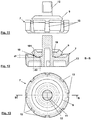
- FIG. 1 is a side view with detail sections a waste set A with filling valve 1 and drain pipe R for installation in a cistern, not shown here, which is filled by means of the drain set A with liquid, here with water, represented.
- the filling valve 1 has an inlet 2 with a flow regulator 3 having a throttle device 4 for reducing the pressure of the fluid flowing in the direction of flow s and a drain 5.
- the FIGS. 2 and 4 each show an enlarged detail according to the section II in FIG. 1 with a first embodiment and a second embodiment of the filling valve 1.
- An associated respective plan view of the flow regulator 3 is in the FIGS. 3 and 5 played.
- the flow regulator 3 is designed according to the invention as a volume flow control 6 and allows a constant volume flow of the liquid as a function of the flow pressure of the liquid at the inlet 2.
- a first embodiment and in the FIGS. 4 and 5 a second embodiment of the volume flow control 6 is shown.
- the volume flow control 6 is arranged in the inlet 2. This has a circular cross-section.
- the volume flow control 6 has a carrier 7 extending over the flow cross section of the inlet 2.
- the support 7 has four primary openings 8, which, depending on the flow pressure of the liquid at the inlet 2, increase it progressively sealingly coverable or arranged with a reduction of the same progressively releasable.
- a flow-effective flow cross-section at the primary openings 8 can be reduced continuously until it becomes zero with a sealing overlap of the primary openings 8.
- the carrier 7 is rotationally symmetrical with respect to a central rotational symmetry axis d parallel to the flow direction s.
- the rotational symmetry axis d is equal to a central axis m.
- the primary openings 8 are arranged with respect to the central axis m of the volume flow control 6 on a first radius r1 and circumferentially equal complaint. They each have a same opening cross-section and are, according to the rotational symmetry by rotation on the rotational symmetry axis congruent superimposed brought.
- a membrane 9 is provided, which is arranged in the flow direction s in front of the primary openings 8.
- the membrane 9 is arranged in an open position shown in the figures of the volume flow control 6, in which the flow pressure is equal to zero, held in an axial direction to the flow direction s distance a. In a closing position of the volume flow control 6, which is not shown here but can easily be deduced from the figures, the membrane 9 bears against the primary openings 8 in a sealing manner.
- spacer bodies here in the form of projections 10 which extend away from the carrier 7 in the direction of flow s and are arranged radially outside the primary openings 8. The membrane 9 abuts the projections 10 axially in the flow direction.
- two projections 10 are provided radially outside per primary opening.
- the membrane 9 is in both embodiments of Volumetric flow control 6 as an annular circular disk with a central plug opening 11 is formed, slid perpendicular to the flow direction s axially displaceable and with elastic expansion at its insertion opening 11 in the flow direction s on a 7 away from the carrier 7 extending projection 12 is fixed.
- the membrane 9 has a stiffness which is high enough to be self-supporting and low enough to provide the required flexibility for bending the membrane 9 towards and covering the primary openings 8.
- secondary openings 13 are in the flow control 6 secondary openings 13 additionally provided. These are permanently open and thus not covered by the membrane 8. They are slot-like introduced radially inwardly into the carrier 7 and have a circular segment-like shape.
- the secondary openings 13 are each divided in the direction of flow, by the inner wall 14 of the secondary openings 13 radially outside of the inlet 2 and radially inwardly formed by the carrier 7, wherein the carrier 7 rests radially outwardly positively against the inlet 2.
- the secondary openings 13 are arranged on a circumferential circle with a second radius r2, which is larger than the circumferential circle with the first radius r1.
- the projections 10 are in turn arranged on a circumferential circle with a third radius r3 which is greater than the first radius r1 and smaller than the second radius r2.
- the sum of the opening cross sections of the primary openings 8 is greater than the sum of the opening cross sections of the secondary openings 13. That is, in the open position, the main portion of the inflowing liquid flows through the primary openings 8. The proportion of flowing liquid through the secondary openings 13 is thus smaller than that through the primary openings 8. If the primary openings 8 are closed, liquid continues to flow through the secondary openings 13.
- the carrier 7 is in turn radially 29iebungsfestaufsteckbar in the flow direction s to form a plug connection to an axially central in an insertion opening 11 on the carrier engaging male projection 12 of the filling valve 1. It can thus be withdrawn together with the membrane 9 against flow direction s of the plug-in projection 12 and possibly cleaned and / or replaced.
- the carrier 8 has a cup-like shape with a peripheral edge 15 and a recess 16, wherein the secondary opening 13 is incorporated in the edge 15 and the membrane 9 is arranged protected in the recess 16.
- the extending against the flow direction s plug projection 12 of the carrier 7 extends through the insertion opening 13 of the annular membrane 9 with a free end 17, through which the carrier 7 with membrane 9 engaged under the inlet 2, pulled out and can be replaced.
- FIGS 8-14 different views of the carrier 7 with and without membrane 9 two different embodiments of the filling valve 1 are shown.
- the membrane 9 on the projections 10 of the in Figures 7-9 shown open position in the in Figure 11-14 shown sealing position to form a defined curved shape, here spherical shape, to be deformed.
- These embodiments differ from the previous design in particular by the arrangement and design of the spacers and the diaphragm 9, whereby a deformation of the diaphragm 9 from the open position into the sealing position into a defined curved shape is made possible.
- Radially opposing projections 10 each have an equal height h1, h2. You are here formed circular cylindrical.
- the membrane 9 is located in the flow direction s loosely adhering to the projections. Furthermore, it is axially slidably mounted on the plug projection 12 via its plug-in opening 11 with play.
- the membrane 9 is formed without curves as a circular disk. Furthermore, it is made of butadiene rubber.
- the projections form in their entirety a ring-like contact surface facing here in the direction of flow e, which here is interrupted by the circumferential spacing of the projections 10 into individual abutment surfaces 18, forming the membrane 8.
- the membrane 8 is flat in the sealing position.
- the abutment surfaces 18 of the projections 10 define the curved shape of the diaphragm 9 in the sealing position (FIG. FIG. 14 ).
- the abutment surface 18 of the individual projections 10 radially outside a here exactly against the flow direction s facing circular segment-like second portion 182 on which the membrane 9 abuts in the open position (see FIG. 7 ).
- the projections 10 each end a wedge-like shape with a wedge angle, in which the wedge-like shape tapers against the flow direction s and radially outward.
- the employment of the first portion 181 of the contact surface 18 also determines the curved shape of the membrane 9.
- the wedge angle is here about 60 °.
- a bearing against the flow direction s facing support surface 19 is provided, to which the membrane 9 applies on the way to its sealing position with an opening edge region of its insertion opening 11.
- This support surface 19 determines the formation of the zenith of the spherical shape of the diaphragm 9 in the sealing position.
- the second portion 182 of the abutment surface 18 is arranged at a certain axial first distance d1.
- the larger the first distance the stronger the membrane 9 is curved in the sealing position.
- the first portion 181 of the abutment surface 18 is arranged at a second distance d2 to the support surface 19, on which the membrane 9 lies flat in the sealing position.
- this second distance d2 in particular determines the formation of the radial center of the membrane 9.
- the embodiments of the filling valve 1 shown in the figures are also distinguished by the fact that the inner wall 14 of the secondary openings 13 is roughened to reduce the emission of noise during the passage of liquid.
- This can not be explicitly stated in the drawing figures designed as a line drawing.
- a purely schematically illustrated detail magnification in FIG. 6a should clarify this roughening.
- the roughening is introduced here into the inner wall 14 by a brushing carried out in the flow direction s.
- the wall of the inlet 2 and of the carrier 7 adjoining the inner wall 14 of the primary opening 8 and the secondary opening 13 in the flow direction s is roughened.
Landscapes
- Engineering & Computer Science (AREA)
- General Engineering & Computer Science (AREA)
- Mechanical Engineering (AREA)
- Health & Medical Sciences (AREA)
- Life Sciences & Earth Sciences (AREA)
- Hydrology & Water Resources (AREA)
- Public Health (AREA)
- Water Supply & Treatment (AREA)
- Physics & Mathematics (AREA)
- General Physics & Mathematics (AREA)
- Automation & Control Theory (AREA)
- Details Of Valves (AREA)
Claims (14)
- Vanne de remplissage pour remplir un réservoir de chasse d'eau avec un liquide, en particulier avec de l'eau, la vanne de remplissage (1) présentant une arrivée (2) avec un dispositif d'étranglement (4) qui présente un régulateur de débit (3) pour réduire la pression du liquide qui afflue dans le sens d'écoulement (s) qui est configuré comme régulation du débit volumétrique (6) pour maintenir une constance du flux volumétrique du liquide en fonction de la pression d'écoulement du liquide à l'arrivée (2) pour réduire les bruits d'écoulement lors du remplissage du réservoir de chasse d'eau, cependant que la régulation du débit volumétrique (6) présente un support (7) qui s'étend sur la section d'écoulement de l'arrivée (2) et qui a au moins une ouverture primaire (8) qui est placée en pouvant être couverte de manière étanche de manière progressive avec l'augmentation de la pression d'écoulement au moyen d'une membrane placée en amont ou pouvant être dégagée de manière progressive avec la diminution de celle-ci, caractérisée en ce que la régulation du débit volumétrique (6) présente au moins une ouverture secondaire (13) qui est configurée ouverte en permanence ce qui garantit qu'une partie du liquide traverse la régulation du débit volumétrique (6) même en cas de recouvrement complètement étanche de la au moins une ouverture primaire (8) tant que la pression d'écoulement du liquide est supérieure à zéro à la au moins une ouverture secondaire (13), cependant que la au moins une ouverture secondaire (13) est délimitée par une paroi intérieure (14) qui est configurée rugueuse et/ou alvéolée pour la réduction de l'émission sonore lors de l'écoulement.
- Vanne de remplissage selon la revendication 1, caractérisée en ce que la membrane (9) est configurée plate dans sa forme de base et qu'elle est placée dans la régulation du débit volumétrique de telle manière qu'elle peut, avec l'augmentation de la pression d'écoulement, être mise en une forme spatiale courbée définie.
- Vanne de remplissage selon la revendication 2, caractérisée en ce que la forme spatiale courbée de la membrane (9) est approximativement celle d'une calotte ellipsoïdale creuse aplatie en son zénith.
- Vanne de remplissage selon la revendication 2 ou 3, caractérisée en ce que la membrane (9) est placée maintenue dans une position ouverte de la régulation du débit volumétrique (6), dans laquelle la pression d'écoulement est égale ou approximativement égale à zéro, au moyen d'au moins un corps d'espacement à une distance axiale (a) par rapport au sens d'écoulement (s) de l'ouverture primaire (8) et, avec l'augmentation de la pression d'écoulement, en formant la forme spatiale courbée, en particulier une forme sphérique aplatie en son zénith, repose sur l'ouverture primaire (8) de manière étanche par rapport au sens d'écoulement (s) en entrant dans une position fermée de la régulation du débit volumétrique (6).
- Vanne de remplissage selon la revendication 4, caractérisée en ce que la membrane (9) repose sur le au moins un corps d'espacement en restant desserrée dans le sens d'écoulement (s).
- Vanne de remplissage selon la revendication 4 ou 5, caractérisée en ce que le au moins un corps d'espacement ou plusieurs corps d'espacement forment en tout une surface d'appui (18) annulaire, en particulier de type anneau circulaire, tournée à l'encontre du sens d'écoulement (s), pour la membrane (9).
- Vanne de remplissage selon la revendication 6, caractérisée en ce qu'au moins une première section (181) de la surface d'appui (18), située radialement à l'intérieur, est configurée biseautée radialement vers l'intérieur dans le sens d'écoulement (s).
- Vanne de remplissage selon l'une des revendications 4 à 7, caractérisée en ce que les corps d'espacement sont configurés comme des saillies qui s'étendent en s'éloignant du support (7) contre le sens d'écoulement (s), cependant que les saillies opposées (10) par rapport à un axe médian (m) présentent une même hauteur (h1, h2).
- Vanne de remplissage selon l'une des revendications précédentes, caractérisée en ce que la membrane (9) est configurée non chargée comme un disque, en particulier comme un disque circulaire qui est relié au support (7) axialement en son milieu en étant radialement fixe en translation, perpendiculairement au sens d'écoulement (s).
- Vanne de remplissage selon la revendication 9, caractérisée en ce que la membrane (9) présente en son centre une ouverture d'emboîtement (13) dans laquelle une saillie d'emboîtement (12) prévue au milieu sur le support (7) et qui s'étend à l'encontre du sens d'écoulement (s) est en prise pour former un raccordement emboîté.
- Vanne de remplissage selon l'une des revendications précédentes, caractérisée en ce qu'au moins deux ouvertures primaires (8), de préférence au moins quatre ouvertures primaires (8) sont prévues qui sont placées sur un premier rayon (r1) par rapport à un axe de symétrie de rotation central (d) et en étant équidistantes sur la circonférence.
- Vanne de remplissage selon l'une des revendications précédentes, caractérisée en ce qu'au moins la paroi intérieure du support (s), en particulier la paroi intérieure du support (7) qui est placée dans le sens d'écoulement (s) derrière les ouvertures primaires, est configurée rugueuse.
- Vanne de remplissage selon l'une des revendications précédentes, caractérisée en ce qu'au moins deux ouvertures secondaires (13), de préférence au moins huit ouvertures secondaires (13) sont prévues qui sont placées sur un second rayon (r2) par rapport à l'axe central (m) parallèlement au sens d'écoulement (s) et de préférence en étant équidistantes sur la circonférence.
- Vanne de remplissage selon l'une des revendications précédentes, caractérisée en ce que la somme des sections d'ouverture des ouvertures primaires (8) est plus grande que la somme des sections d'ouverture des ouvertures secondaires (13).
Applications Claiming Priority (2)
| Application Number | Priority Date | Filing Date | Title |
|---|---|---|---|
| DE102014114548.8A DE102014114548A1 (de) | 2014-10-07 | 2014-10-07 | Füllventil |
| PCT/EP2015/073055 WO2016055481A1 (fr) | 2014-10-07 | 2015-10-06 | Vanne de remplissage |
Publications (2)
| Publication Number | Publication Date |
|---|---|
| EP3204561A1 EP3204561A1 (fr) | 2017-08-16 |
| EP3204561B1 true EP3204561B1 (fr) | 2018-08-22 |
Family
ID=54256751
Family Applications (1)
| Application Number | Title | Priority Date | Filing Date |
|---|---|---|---|
| EP15775448.2A Active EP3204561B1 (fr) | 2014-10-07 | 2015-10-06 | Vanne de remplissage |
Country Status (4)
| Country | Link |
|---|---|
| EP (1) | EP3204561B1 (fr) |
| CN (1) | CN107208409B (fr) |
| DE (1) | DE102014114548A1 (fr) |
| WO (1) | WO2016055481A1 (fr) |
Families Citing this family (4)
| Publication number | Priority date | Publication date | Assignee | Title |
|---|---|---|---|---|
| DE202017007227U1 (de) * | 2017-03-27 | 2020-02-13 | Tece Gmbh | Hygienestation |
| EP3736388B1 (fr) | 2019-05-09 | 2023-11-22 | TECE GmbH | Soupape de remplissage pourvue de protection contre la contamination |
| DE202019104935U1 (de) * | 2019-09-06 | 2020-12-08 | Neoperl Gmbh | Durchflussmengenregler |
| RU203921U1 (ru) * | 2020-12-22 | 2021-04-28 | Общество с ограниченной ответственностью "Газпром трансгаз Ухта" | Регулирующий клапан |
Family Cites Families (10)
| Publication number | Priority date | Publication date | Assignee | Title |
|---|---|---|---|---|
| DE941334C (de) * | 1952-11-23 | 1956-04-05 | Benkiser Werke Kommandit Ges | Drosselorgan mit einer auf Druckdifferenz durch die Stroemung ansprechenden veraenderlichen Drosselstelle |
| IL50771A (en) * | 1976-10-27 | 1988-08-31 | Bron Dan | Fluid flow-rate control device |
| IT1319015B1 (it) * | 2000-10-20 | 2003-09-19 | Oliveira & Irmao Sa | Valvola di alimentazione a bassa rumorosita' per una cassetta dirisciacquamento |
| DE10311502B4 (de) * | 2003-03-15 | 2005-09-08 | Neoperl Gmbh | Einbauteil zum Einsetzen in eine Gas- oder Flüssigkeitsleitung |
| HU230292B1 (hu) * | 2006-03-13 | 2015-12-28 | BERY INTELLECTUAL PROPERTIES Szellemi Tulajdonjogokat Hasznosító és Kezelő Kf | Szabályozószelep alakos tömítőelemmel |
| SI1862604T1 (sl) | 2006-06-02 | 2017-08-31 | Sanitaertechnik Eisenberg Gmbh | Polnilni ventil |
| US8820358B2 (en) * | 2009-02-25 | 2014-09-02 | Hewlett-Packard Development Company, L.P. | Check valve |
| FR2986847B1 (fr) * | 2012-02-09 | 2014-12-05 | Coutier Moulage Gen Ind | Clapet anti-retour a membrane |
| FR2991423B1 (fr) * | 2012-05-30 | 2015-05-01 | Coutier Moulage Gen Ind | Clapet anti-retour du type a membrane |
| TWI468607B (zh) * | 2012-07-12 | 2015-01-11 | Delta Electronics Inc | 穩流裝置 |
-
2014
- 2014-10-07 DE DE102014114548.8A patent/DE102014114548A1/de not_active Ceased
-
2015
- 2015-10-06 WO PCT/EP2015/073055 patent/WO2016055481A1/fr not_active Ceased
- 2015-10-06 CN CN201580065059.1A patent/CN107208409B/zh active Active
- 2015-10-06 EP EP15775448.2A patent/EP3204561B1/fr active Active
Non-Patent Citations (1)
| Title |
|---|
| None * |
Also Published As
| Publication number | Publication date |
|---|---|
| EP3204561A1 (fr) | 2017-08-16 |
| WO2016055481A1 (fr) | 2016-04-14 |
| CN107208409B (zh) | 2018-10-02 |
| DE102014114548A1 (de) | 2016-04-07 |
| CN107208409A (zh) | 2017-09-26 |
Similar Documents
| Publication | Publication Date | Title |
|---|---|---|
| DE2729458C3 (de) | Strömungsregulator, insbesondere zum Einbau zwischen einem Wasserkran und einem Wasserleitungsende | |
| EP2757299B1 (fr) | Dispositif de serrage de tuyau | |
| EP3204561B1 (fr) | Vanne de remplissage | |
| DE60310346T2 (de) | Verschlussstopfen für eine Öffnung in einem Bauteil | |
| EP2420708B1 (fr) | Vanne de commande | |
| EP3268547B1 (fr) | Pièce insérable par ajustement serré dans une section de conduit | |
| DE102010064074A1 (de) | Stoßdämpfer | |
| EP3850260B1 (fr) | Dispositif de raccordement de canalisations avec indication de fuite | |
| EP4025812B1 (fr) | Joint métallique pour une soupape à clapet | |
| DE102009001099A1 (de) | Kraftstoffeinspritzventil | |
| EP3827189B1 (fr) | Moyen d'arrêt | |
| EP0492111A2 (fr) | Régulateur d'écoulement | |
| EP4088053A1 (fr) | Soupape et pompe à membrane ayant des soupapes d'entrée et de sortie | |
| DE202023105489U1 (de) | Ventilkäfig für ein Stellventil mit elastischem Bereich | |
| DE4301004C2 (de) | Dichtung für Armaturen | |
| EP1235011A1 (fr) | Dispositif de joint | |
| DE102022132645A1 (de) | Druckausgleichsvorrichtung für ein Gehäuse | |
| DE2525708A1 (de) | Anordnung fuer ventilstangenstoessel | |
| WO2018104265A1 (fr) | Buse à obturation pour jet de liquide | |
| DE2915889A1 (de) | Drehschieber | |
| EP4352391B1 (fr) | Lanterne de soupape destinée à une soupape de commande | |
| EP1447601B1 (fr) | Soupape à siège double | |
| DE102008009714A1 (de) | Gasventil mit Vorentlastung | |
| EP1614948B1 (fr) | Soupape | |
| DE3834997A1 (de) | Wasserauslaufarmatur mit schalldaempfereinsatz |
Legal Events
| Date | Code | Title | Description |
|---|---|---|---|
| PUAI | Public reference made under article 153(3) epc to a published international application that has entered the european phase |
Free format text: ORIGINAL CODE: 0009012 |
|
| 17P | Request for examination filed |
Effective date: 20170406 |
|
| AK | Designated contracting states |
Kind code of ref document: A1 Designated state(s): AL AT BE BG CH CY CZ DE DK EE ES FI FR GB GR HR HU IE IS IT LI LT LU LV MC MK MT NL NO PL PT RO RS SE SI SK SM TR |
|
| AX | Request for extension of the european patent |
Extension state: BA ME |
|
| DAV | Request for validation of the european patent (deleted) | ||
| DAX | Request for extension of the european patent (deleted) | ||
| REG | Reference to a national code |
Ref country code: DE Ref legal event code: R079 Ref document number: 502015005587 Country of ref document: DE Free format text: PREVIOUS MAIN CLASS: E03D0001320000 Ipc: F16K0031340000 |
|
| GRAP | Despatch of communication of intention to grant a patent |
Free format text: ORIGINAL CODE: EPIDOSNIGR1 |
|
| RIC1 | Information provided on ipc code assigned before grant |
Ipc: G05D 7/01 20060101ALI20180410BHEP Ipc: F16K 31/34 20060101AFI20180410BHEP Ipc: E03D 1/32 20060101ALI20180410BHEP Ipc: F16K 47/02 20060101ALI20180410BHEP |
|
| INTG | Intention to grant announced |
Effective date: 20180514 |
|
| GRAS | Grant fee paid |
Free format text: ORIGINAL CODE: EPIDOSNIGR3 |
|
| GRAA | (expected) grant |
Free format text: ORIGINAL CODE: 0009210 |
|
| AK | Designated contracting states |
Kind code of ref document: B1 Designated state(s): AL AT BE BG CH CY CZ DE DK EE ES FI FR GB GR HR HU IE IS IT LI LT LU LV MC MK MT NL NO PL PT RO RS SE SI SK SM TR |
|
| REG | Reference to a national code |
Ref country code: GB Ref legal event code: FG4D Free format text: NOT ENGLISH |
|
| REG | Reference to a national code |
Ref country code: CH Ref legal event code: EP |
|
| REG | Reference to a national code |
Ref country code: AT Ref legal event code: REF Ref document number: 1032927 Country of ref document: AT Kind code of ref document: T Effective date: 20180915 |
|
| REG | Reference to a national code |
Ref country code: IE Ref legal event code: FG4D Free format text: LANGUAGE OF EP DOCUMENT: GERMAN |
|
| REG | Reference to a national code |
Ref country code: DE Ref legal event code: R096 Ref document number: 502015005587 Country of ref document: DE |
|
| REG | Reference to a national code |
Ref country code: NL Ref legal event code: MP Effective date: 20180822 |
|
| REG | Reference to a national code |
Ref country code: LT Ref legal event code: MG4D |
|
| PG25 | Lapsed in a contracting state [announced via postgrant information from national office to epo] |
Ref country code: LT Free format text: LAPSE BECAUSE OF FAILURE TO SUBMIT A TRANSLATION OF THE DESCRIPTION OR TO PAY THE FEE WITHIN THE PRESCRIBED TIME-LIMIT Effective date: 20180822 Ref country code: BG Free format text: LAPSE BECAUSE OF FAILURE TO SUBMIT A TRANSLATION OF THE DESCRIPTION OR TO PAY THE FEE WITHIN THE PRESCRIBED TIME-LIMIT Effective date: 20181122 Ref country code: NL Free format text: LAPSE BECAUSE OF FAILURE TO SUBMIT A TRANSLATION OF THE DESCRIPTION OR TO PAY THE FEE WITHIN THE PRESCRIBED TIME-LIMIT Effective date: 20180822 Ref country code: SE Free format text: LAPSE BECAUSE OF FAILURE TO SUBMIT A TRANSLATION OF THE DESCRIPTION OR TO PAY THE FEE WITHIN THE PRESCRIBED TIME-LIMIT Effective date: 20180822 Ref country code: IS Free format text: LAPSE BECAUSE OF FAILURE TO SUBMIT A TRANSLATION OF THE DESCRIPTION OR TO PAY THE FEE WITHIN THE PRESCRIBED TIME-LIMIT Effective date: 20181222 Ref country code: FI Free format text: LAPSE BECAUSE OF FAILURE TO SUBMIT A TRANSLATION OF THE DESCRIPTION OR TO PAY THE FEE WITHIN THE PRESCRIBED TIME-LIMIT Effective date: 20180822 Ref country code: RS Free format text: LAPSE BECAUSE OF FAILURE TO SUBMIT A TRANSLATION OF THE DESCRIPTION OR TO PAY THE FEE WITHIN THE PRESCRIBED TIME-LIMIT Effective date: 20180822 Ref country code: NO Free format text: LAPSE BECAUSE OF FAILURE TO SUBMIT A TRANSLATION OF THE DESCRIPTION OR TO PAY THE FEE WITHIN THE PRESCRIBED TIME-LIMIT Effective date: 20181122 Ref country code: GR Free format text: LAPSE BECAUSE OF FAILURE TO SUBMIT A TRANSLATION OF THE DESCRIPTION OR TO PAY THE FEE WITHIN THE PRESCRIBED TIME-LIMIT Effective date: 20181123 |
|
| PG25 | Lapsed in a contracting state [announced via postgrant information from national office to epo] |
Ref country code: LV Free format text: LAPSE BECAUSE OF FAILURE TO SUBMIT A TRANSLATION OF THE DESCRIPTION OR TO PAY THE FEE WITHIN THE PRESCRIBED TIME-LIMIT Effective date: 20180822 Ref country code: HR Free format text: LAPSE BECAUSE OF FAILURE TO SUBMIT A TRANSLATION OF THE DESCRIPTION OR TO PAY THE FEE WITHIN THE PRESCRIBED TIME-LIMIT Effective date: 20180822 Ref country code: AL Free format text: LAPSE BECAUSE OF FAILURE TO SUBMIT A TRANSLATION OF THE DESCRIPTION OR TO PAY THE FEE WITHIN THE PRESCRIBED TIME-LIMIT Effective date: 20180822 |
|
| PG25 | Lapsed in a contracting state [announced via postgrant information from national office to epo] |
Ref country code: ES Free format text: LAPSE BECAUSE OF FAILURE TO SUBMIT A TRANSLATION OF THE DESCRIPTION OR TO PAY THE FEE WITHIN THE PRESCRIBED TIME-LIMIT Effective date: 20180822 Ref country code: EE Free format text: LAPSE BECAUSE OF FAILURE TO SUBMIT A TRANSLATION OF THE DESCRIPTION OR TO PAY THE FEE WITHIN THE PRESCRIBED TIME-LIMIT Effective date: 20180822 Ref country code: IT Free format text: LAPSE BECAUSE OF FAILURE TO SUBMIT A TRANSLATION OF THE DESCRIPTION OR TO PAY THE FEE WITHIN THE PRESCRIBED TIME-LIMIT Effective date: 20180822 Ref country code: RO Free format text: LAPSE BECAUSE OF FAILURE TO SUBMIT A TRANSLATION OF THE DESCRIPTION OR TO PAY THE FEE WITHIN THE PRESCRIBED TIME-LIMIT Effective date: 20180822 Ref country code: CZ Free format text: LAPSE BECAUSE OF FAILURE TO SUBMIT A TRANSLATION OF THE DESCRIPTION OR TO PAY THE FEE WITHIN THE PRESCRIBED TIME-LIMIT Effective date: 20180822 Ref country code: PL Free format text: LAPSE BECAUSE OF FAILURE TO SUBMIT A TRANSLATION OF THE DESCRIPTION OR TO PAY THE FEE WITHIN THE PRESCRIBED TIME-LIMIT Effective date: 20180822 |
|
| REG | Reference to a national code |
Ref country code: DE Ref legal event code: R097 Ref document number: 502015005587 Country of ref document: DE |
|
| PG25 | Lapsed in a contracting state [announced via postgrant information from national office to epo] |
Ref country code: DK Free format text: LAPSE BECAUSE OF FAILURE TO SUBMIT A TRANSLATION OF THE DESCRIPTION OR TO PAY THE FEE WITHIN THE PRESCRIBED TIME-LIMIT Effective date: 20180822 Ref country code: SK Free format text: LAPSE BECAUSE OF FAILURE TO SUBMIT A TRANSLATION OF THE DESCRIPTION OR TO PAY THE FEE WITHIN THE PRESCRIBED TIME-LIMIT Effective date: 20180822 Ref country code: SM Free format text: LAPSE BECAUSE OF FAILURE TO SUBMIT A TRANSLATION OF THE DESCRIPTION OR TO PAY THE FEE WITHIN THE PRESCRIBED TIME-LIMIT Effective date: 20180822 |
|
| REG | Reference to a national code |
Ref country code: CH Ref legal event code: PL |
|
| REG | Reference to a national code |
Ref country code: BE Ref legal event code: MM Effective date: 20181031 |
|
| PG25 | Lapsed in a contracting state [announced via postgrant information from national office to epo] |
Ref country code: LU Free format text: LAPSE BECAUSE OF NON-PAYMENT OF DUE FEES Effective date: 20181006 Ref country code: MC Free format text: LAPSE BECAUSE OF FAILURE TO SUBMIT A TRANSLATION OF THE DESCRIPTION OR TO PAY THE FEE WITHIN THE PRESCRIBED TIME-LIMIT Effective date: 20180822 |
|
| PLBE | No opposition filed within time limit |
Free format text: ORIGINAL CODE: 0009261 |
|
| STAA | Information on the status of an ep patent application or granted ep patent |
Free format text: STATUS: NO OPPOSITION FILED WITHIN TIME LIMIT |
|
| REG | Reference to a national code |
Ref country code: IE Ref legal event code: MM4A |
|
| 26N | No opposition filed |
Effective date: 20190523 |
|
| PG25 | Lapsed in a contracting state [announced via postgrant information from national office to epo] |
Ref country code: CH Free format text: LAPSE BECAUSE OF NON-PAYMENT OF DUE FEES Effective date: 20181031 Ref country code: SI Free format text: LAPSE BECAUSE OF FAILURE TO SUBMIT A TRANSLATION OF THE DESCRIPTION OR TO PAY THE FEE WITHIN THE PRESCRIBED TIME-LIMIT Effective date: 20180822 Ref country code: LI Free format text: LAPSE BECAUSE OF NON-PAYMENT OF DUE FEES Effective date: 20181031 Ref country code: FR Free format text: LAPSE BECAUSE OF NON-PAYMENT OF DUE FEES Effective date: 20181022 Ref country code: BE Free format text: LAPSE BECAUSE OF NON-PAYMENT OF DUE FEES Effective date: 20181031 |
|
| PG25 | Lapsed in a contracting state [announced via postgrant information from national office to epo] |
Ref country code: IE Free format text: LAPSE BECAUSE OF NON-PAYMENT OF DUE FEES Effective date: 20181006 |
|
| PG25 | Lapsed in a contracting state [announced via postgrant information from national office to epo] |
Ref country code: MT Free format text: LAPSE BECAUSE OF FAILURE TO SUBMIT A TRANSLATION OF THE DESCRIPTION OR TO PAY THE FEE WITHIN THE PRESCRIBED TIME-LIMIT Effective date: 20180822 |
|
| PG25 | Lapsed in a contracting state [announced via postgrant information from national office to epo] |
Ref country code: TR Free format text: LAPSE BECAUSE OF FAILURE TO SUBMIT A TRANSLATION OF THE DESCRIPTION OR TO PAY THE FEE WITHIN THE PRESCRIBED TIME-LIMIT Effective date: 20180822 |
|
| PG25 | Lapsed in a contracting state [announced via postgrant information from national office to epo] |
Ref country code: PT Free format text: LAPSE BECAUSE OF FAILURE TO SUBMIT A TRANSLATION OF THE DESCRIPTION OR TO PAY THE FEE WITHIN THE PRESCRIBED TIME-LIMIT Effective date: 20180822 |
|
| PG25 | Lapsed in a contracting state [announced via postgrant information from national office to epo] |
Ref country code: MK Free format text: LAPSE BECAUSE OF NON-PAYMENT OF DUE FEES Effective date: 20180822 Ref country code: HU Free format text: LAPSE BECAUSE OF FAILURE TO SUBMIT A TRANSLATION OF THE DESCRIPTION OR TO PAY THE FEE WITHIN THE PRESCRIBED TIME-LIMIT; INVALID AB INITIO Effective date: 20151006 Ref country code: CY Free format text: LAPSE BECAUSE OF FAILURE TO SUBMIT A TRANSLATION OF THE DESCRIPTION OR TO PAY THE FEE WITHIN THE PRESCRIBED TIME-LIMIT Effective date: 20180822 |
|
| GBPC | Gb: european patent ceased through non-payment of renewal fee |
Effective date: 20191006 |
|
| PG25 | Lapsed in a contracting state [announced via postgrant information from national office to epo] |
Ref country code: GB Free format text: LAPSE BECAUSE OF NON-PAYMENT OF DUE FEES Effective date: 20191006 |
|
| REG | Reference to a national code |
Ref country code: AT Ref legal event code: MM01 Ref document number: 1032927 Country of ref document: AT Kind code of ref document: T Effective date: 20201006 |
|
| PG25 | Lapsed in a contracting state [announced via postgrant information from national office to epo] |
Ref country code: AT Free format text: LAPSE BECAUSE OF NON-PAYMENT OF DUE FEES Effective date: 20201006 |
|
| P01 | Opt-out of the competence of the unified patent court (upc) registered |
Effective date: 20230527 |
|
| PGFP | Annual fee paid to national office [announced via postgrant information from national office to epo] |
Ref country code: DE Payment date: 20251024 Year of fee payment: 11 |
|
| REG | Reference to a national code |
Ref country code: DE Ref legal event code: R081 Ref document number: 502015005587 Country of ref document: DE Owner name: TECE SE, DE Free format text: FORMER OWNER: TECE GMBH, 48282 EMSDETTEN, DE |