EP3205457A1 - Übertragungsverfahren und übertragungsvorrichtung - Google Patents
Übertragungsverfahren und übertragungsvorrichtung Download PDFInfo
- Publication number
- EP3205457A1 EP3205457A1 EP14903589.1A EP14903589A EP3205457A1 EP 3205457 A1 EP3205457 A1 EP 3205457A1 EP 14903589 A EP14903589 A EP 14903589A EP 3205457 A1 EP3205457 A1 EP 3205457A1
- Authority
- EP
- European Patent Office
- Prior art keywords
- end section
- component
- robot
- target
- target position
- Prior art date
- Legal status (The legal status is an assumption and is not a legal conclusion. Google has not performed a legal analysis and makes no representation as to the accuracy of the status listed.)
- Granted
Links
Images


Classifications
-
- B—PERFORMING OPERATIONS; TRANSPORTING
- B25—HAND TOOLS; PORTABLE POWER-DRIVEN TOOLS; MANIPULATORS
- B25J—MANIPULATORS; CHAMBERS PROVIDED WITH MANIPULATION DEVICES
- B25J9/00—Program-controlled manipulators
- B25J9/16—Program controls
- B25J9/1628—Program controls characterised by the control loop
- B25J9/1641—Program controls characterised by the control loop compensation for backlash, friction, compliance, elasticity in the joints
-
- B—PERFORMING OPERATIONS; TRANSPORTING
- B25—HAND TOOLS; PORTABLE POWER-DRIVEN TOOLS; MANIPULATORS
- B25J—MANIPULATORS; CHAMBERS PROVIDED WITH MANIPULATION DEVICES
- B25J13/00—Controls for manipulators
- B25J13/08—Controls for manipulators by means of sensing devices, e.g. viewing or touching devices
- B25J13/088—Controls for manipulators by means of sensing devices, e.g. viewing or touching devices with position, velocity or acceleration sensors
-
- B—PERFORMING OPERATIONS; TRANSPORTING
- B25—HAND TOOLS; PORTABLE POWER-DRIVEN TOOLS; MANIPULATORS
- B25J—MANIPULATORS; CHAMBERS PROVIDED WITH MANIPULATION DEVICES
- B25J15/00—Gripping heads and other end effectors
- B25J15/06—Gripping heads and other end effectors with vacuum or magnetic holding means
- B25J15/0616—Gripping heads and other end effectors with vacuum or magnetic holding means with vacuum
-
- B—PERFORMING OPERATIONS; TRANSPORTING
- B25—HAND TOOLS; PORTABLE POWER-DRIVEN TOOLS; MANIPULATORS
- B25J—MANIPULATORS; CHAMBERS PROVIDED WITH MANIPULATION DEVICES
- B25J9/00—Program-controlled manipulators
- B25J9/16—Program controls
- B25J9/1694—Program controls characterised by use of sensors other than normal servo-feedback from position, speed or acceleration sensors, perception control, multi-sensor controlled systems, sensor fusion
- B25J9/1697—Vision controlled systems
-
- G—PHYSICS
- G05—CONTROLLING; REGULATING
- G05B—CONTROL OR REGULATING SYSTEMS IN GENERAL; FUNCTIONAL ELEMENTS OF SUCH SYSTEMS; MONITORING OR TESTING ARRANGEMENTS FOR SUCH SYSTEMS OR ELEMENTS
- G05B2219/00—Program-control systems
- G05B2219/30—Nc systems
- G05B2219/39—Robotics, robotics to robotics hand
- G05B2219/39195—Control, avoid oscillation, vibration due to low rigidity
-
- G—PHYSICS
- G05—CONTROLLING; REGULATING
- G05B—CONTROL OR REGULATING SYSTEMS IN GENERAL; FUNCTIONAL ELEMENTS OF SUCH SYSTEMS; MONITORING OR TESTING ARRANGEMENTS FOR SUCH SYSTEMS OR ELEMENTS
- G05B2219/00—Program-control systems
- G05B2219/30—Nc systems
- G05B2219/39—Robotics, robotics to robotics hand
- G05B2219/39241—Force and vibration control
-
- G—PHYSICS
- G05—CONTROLLING; REGULATING
- G05B—CONTROL OR REGULATING SYSTEMS IN GENERAL; FUNCTIONAL ELEMENTS OF SUCH SYSTEMS; MONITORING OR TESTING ARRANGEMENTS FOR SUCH SYSTEMS OR ELEMENTS
- G05B2219/00—Program-control systems
- G05B2219/30—Nc systems
- G05B2219/42—Servomotor, servo controller kind till VSS
- G05B2219/42077—Position, speed or current, combined with vibration feedback
-
- G—PHYSICS
- G05—CONTROLLING; REGULATING
- G05B—CONTROL OR REGULATING SYSTEMS IN GENERAL; FUNCTIONAL ELEMENTS OF SUCH SYSTEMS; MONITORING OR TESTING ARRANGEMENTS FOR SUCH SYSTEMS OR ELEMENTS
- G05B2219/00—Program-control systems
- G05B2219/30—Nc systems
- G05B2219/45—Nc applications
- G05B2219/45063—Pick and place manipulator
-
- G—PHYSICS
- G05—CONTROLLING; REGULATING
- G05D—SYSTEMS FOR CONTROLLING OR REGULATING NON-ELECTRIC VARIABLES
- G05D19/00—Control of mechanical oscillations, e.g. of amplitude, of frequency, of phase
- G05D19/02—Control of mechanical oscillations, e.g. of amplitude, of frequency, of phase characterised by the use of electric means
Definitions
- the present invention relates to a conveyance method and a conveyance device using a robot an end section of which is movable in a first direction and a second direction, that loads a target object held by the end section by conveying the target object to a specified target position.
- Conveyance devices that convey work are well-known.
- disclosed in patent literature 1 is an item that, in a conveyance system provided with a conveyance device that conveys a work and a work robot that performs work on the work during conveyance, eliminates the influence of vibration between the robot and the work by predicting a vibration pattern that arises in the work during conveyance and recreating the vibration that arises in the work in the work robot based on the predicted vibration pattern.
- Patent Literature 1 JP-A-2014-14894
- a system that performs work on a work during conveyance of the work in this manner is able to eliminate the influence of vibration that arises in the work (target object), but because the work itself continues to experience vibration, it is not appropriate in a case in which the work is being loaded to a target position.
- An object of the present invention is to improve the loading accuracy of a target object for an item that conveys and loads a target object held by an end section of a robot to a specified target position.
- the present invention using the following means to achieve the above object.
- the present invention of a conveyance method includes:
- first direction movement control is performed such that the position in the first direction of the end section holding the target object matches the first target position
- the vibration waveform of the end section in the first direction is measured after first direction movement control has been performed
- second direction movement control to load the target object by controlling the robot such that the position of the end section in the second direction matches the second target position at a specified timing during vibration is performed based on the vibration waveform. According, the loading accuracy of the target object is improved.
- the second direction movement control may be performed to control the robot such that the position of the end section in the second direction matches the second target position when a displacement of the end section in the first direction becomes a node of the vibration waveform as the specified timing during vibration. Accordingly, a vibrating target object can be loaded to the target position with good accuracy.
- the end section may be provided with an imaging means, and the vibration waveform of the end section in the first direction measured based on multiple images obtained by the imaging means performing imaging multiple times after the performing of the first direction movement control; or the end section may be provided with an acceleration sensor, and the vibration waveform of the end section in the first direction measured based on an acceleration detected by the acceleration sensor; or the vibration waveform of the end section in the first direction may be predicted based on a control instruction signal used when the robot is controlled by the first direction movement control.
- the vibration waveform of the end section in the first direction after the first direction movement control has been performed may be predicted or learned
- the first direction movement control may control the robot such that the position of the end section in the first direction matches a position deviated from the first target position by the amplitude of the vibration waveform that was predicted or learned
- the second direction movement control may control the robot such that the position of the end section in the second direction matches the second target position when the displacement of the end section in the first direction becomes an antinode of the vibration waveform as the specified timing during vibration. Accordingly, a vibrating target object can be loaded to the target position with good accuracy.
- a conveyance device of the present invention is a conveyance device that performs specified work at a specified target position, and includes: a robot provided with an end section able to hold the target object and move in a first direction and a second direction; a target position acquiring means configured to acquire a first target position that is a target position in the first direction, and a second target position that is a target position in the second direction as the specified target positions; a first direction movement control means configured to perform first direction movement control on the robot such that the position of the robot in the first direction matches the first target position; a vibration waveform acquiring means configured to acquire a vibration waveform of the end section in the first direction after the first direction movement control has been performed; and a second direction movement control means configured to perform second direction movement control on the robot such that the position of the end section in the second direction matches the second target position at a specified timing during vibration, based on the acquired vibration waveform of the end section in the first direction.
- a conveyance device of the present invention it is possible to achieve the same effect as the above conveyance method, that is, the effect of improving the loading accuracy of a target object.
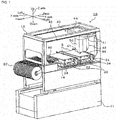
- Fig. 1 is a configuration diagram showing an outline of the configuration of component mounter 10, which is an embodiment of the present invention
- fig. 2 shows the electrical connections of control device 70 of component mounter 10. Note that, in fig. 1 the left-right direction is the X-axis direction, the front-rear direction is the Y-axis direction, and the up-down direction is Z-axis direction.
- Component mounter 10 picks up component P, conveys component P to board S, and mounts component P at a target position on board S.
- component mounter 10 is provided with board conveyance device 30 configured to convey board S, component supply device 20 configured to supply components P, head 50 that picks up component P supplied from component supply device 20 using suction nozzle 51 and mounts component P on board S conveyed by board conveyance device 30, XY robot 40 that moves head 50 in the XY direction, and control device 70 that controls the mounting machine overall (refer to fig. 2 ).
- component mounter 10 in addition to the above, is equipped with mark camera 56 provided on head 50 for imaging board positioning reference marks provided on board S, acceleration sensor 55 (refer to fig. 2 ) provided near suction nozzle 51 of head 50 that detects acceleration ⁇ in the Y direction, component camera 60 for imaging the holding orientation of component P picked up by suction nozzle 51, and the like.
- Component supply device 20 may use a tape feeder that supplies component by feeding carrier tape.
- board conveyance device 30 is provided with belt conveyor device 32, and board S is conveyed from the left to the right in fig. 1 (board conveyance direction) by the driving of belt conveyor device 32.
- Backup plate 34 for supporting conveyed board S from beneath is provided in a central portion of board conveyance device 30 in the board conveyance direction (X-axis direction).
- head 50 is provided with Z-axis actuator 52 that moves suction nozzle 51 in the up-down direction (Z direction) and ⁇ -axis actuator 54 that rotates suction nozzle 51 around the Z-axis.
- the suction opening of suction nozzle 51 selectively connects to vacuum pump 58 or air pipe 59 via electromagnetic valve 57.
- Control device 70 is able to pick up component P using negative pressure at the suction opening of suction nozzle 51 by connecting the suction opening of suction nozzle 51 to vacuum pump 58 and then operating electromagnetic valve 57, and is able to release component P using positive pressure at the suction opening of suction nozzle 51 by connecting the suction opening of suction nozzle 51 to air pipe 59 and then operating electromagnetic valve 57.
- XY robot 40 is provided with Y-axis guide rail 43 attached to an upper level of main body frame 12 extending in the front-rear direction (Y direction), Y-axis slider 44 that is able to slide along Y-axis guide rail 43 while being supported on Y-axis guide rail 43, X-axis guide rail 41 attached to the lower surface of Y-axis slider 44 extending in the left-right direction (X direction), and X-axis slider 42 that is able to slide along X-axis guide rail 41.
- Head 50 is attached to X-axis slider 42, and control device 70 is able to move head 50 to any position in an XY plane by controlling XY robot 40.
- Mark camera 56 images board positioning reference marks provided on board S, and outputs a captured image to control device 70.
- Control device 70 to which the image is inputted recognizes the backup position of board S based on the image.
- control device 70 is configured from CPU 71 that is based around a microprocessor, and is also provided with ROM 72, HDD 73, RAM 74, and input/output interface 75. These items are electrically connected by bus 76.
- a control signal to component supply device 20, a control signal to board conveyance device 30, a drive signal to X-axis actuator 46 that moves X-axis slider 42, a drive signal to Y-axis actuator 48 that moves Y-axis slider 44, a drive signal Z-axis actuator 52, a drive signal to ⁇ -axis actuator 54, a drive signal to electromagnetic valve 57, and so on, are inputted to control device 70 via input/output interface 75.
- FIG. 3 is a flowchart showing an example of component mounting processing performed by CPU 71 of control device 70. This processing is performed when an operator gives an instruction to perform mounting (production) of components P on board S.
- first CPU 71 of control device 70 inputs the target mounting position (X*, Y*, Z*) of board S (S100). Continuing, CPU 71 performs pickup operation of causing suction nozzle 51 to pick up component P supplied from component supply device 20 (S110).
- pickup operation specifically means, after controlling XY robot 40 such that suction nozzle 51 attached to head 50 comes directly above component P, controlling Z-axis actuator 52 such that the suction opening of suction nozzle 51 contacts component P, and controlling electromagnetic valve 57 to supply negative pressure to the suction opening of suction nozzle 51.
- CPU 71 controls XY robot 40 such that the component P picked up by suction nozzle 51 matches the target mounting position (X*, Y*) in the XY plane (S120), and inputs the current position in the XY plane (current XY coordinates) of the component P detected by X-axis position sensor 47 and Y-axis position sensor 49 (S130).
- CPU 71 determines whether the inputted current position of component P is near the target mounting position in the XY plane (X*, Y*) (S140), and if it is determined that the current position is near the target mounting position (X*, Y*), enters acceleration ⁇ in the Y direction of suction nozzle 51 (component P) from acceleration sensor 55 (S150), and measures the vibration waveform in the Y direction of component P based on the inputted acceleration ⁇ in the Y direction and the Y coordinate (displacement y in the Y direction) of the current position of component P inputted in S130.
- CPU 71 sets (S170) control timing in the Z direction such that displacement y of component P in the Y direction crosses a node of the vibration waveform of the Y component measured in S160 when the time required for component P to be moved in the Z direction from the current position and mounted on board S will have elapsed, and controls (S180) Z-axis actuator 52 such that component P is moved in the Z direction and mounted on board S according to the set control timing.
- the required time for example, is obtained by performing experiments in advance of the elapsed time of moving component P in the Z direction to mounting component P on board S.
- Figs. 4 and 5 illustrate the waveforms of robot end coordinates over time as XY robot 40 is operated.
- Fig. 4 shows the waveform over time for the embodiment
- fig. 5 shows the waveform over time of a comparative example.
- the vibration waveform in the Y direction is measured, and control of movement in the Z direction is performed such that component P arrives at the target Z coordinate (value zero) as displacement y of component P in the Y direction crosses a node of the vibration waveform.
- component P is mounted on board S at the earliest possible timing without measuring the vibration waveform.
- component P is mounted at a position deviated from the target Y coordinate.
- Component mounting processing 10 of the present embodiment described above after moving component P picked up by suction nozzle 51 towards the target XY coordinates, measures the waveform of the vibration (vibration waveform) arising in component P, and controls Z-axis actuator 52 such that component P arrives at the target Z coordinate (value zero) when displacement y of component P crosses a node of the measured vibration waveform.
- the mounting position accuracy of component P is improved while shortening the time required for mounting.
- control is performed such that component P arrives at the target Z coordinate (value zero) when displacement y of the robot end (component P) crosses a node of the measured vibration waveform
- embodiments are not restricted to this, and may also be configured as follows.
- Amplitude A of vibration arising in the robot end (component P) when the robot end (component P) arrives near the target XY coordinates may be experimentally obtained in advance, and the target Y coordinate may be set as a corrected target Y coordinate that is shifted by amplitude A, and CPU 71 may control XY robot 40 such that component P moves to the target X coordinate and the corrected target Y coordinate when receiving an instruction to move and mount component P.
- CPU 71 may measure the vibration waveform in the Y direction of the robot end (component P), and set control timing in the Z direction such that displacement y of component P in the Y direction passes through an antinode of the vibration waveform of the Y component that was measured when the time required for component P to be moved in the Z direction from the current position and mounted on board S will have elapsed, and may control Z-axis actuator 52 such that component P is moved in the Z direction and mounted on board S according to the set control timing.
- component mounting processing 10 of the embodiment in a case in which the movement distance is longer in the Y direction than in the X direction when component P is moved to the target XY coordinates, only the Y component of the vibration arising in the robot end (component P) after component P has arrived near the target XY coordinates is considered, but embodiments are not limited to this, and in a case in which the movement distance is longer in the X direction than in the Y direction when component P is moved to the target XY coordinates, only the X component of the vibration arising in the robot end (component P) after component P has arrived near the target XY coordinates may be considered, or both the X and the Y component of the vibration arising in the robot end (component P) after component P has arrived near the target XY coordinates may be considered.
- the vibration waveform of the X component and the vibration waveform of the Y component when component P arrives near the target XY coordinates may be measured, and control may be performed such that component P arrives at the target Z coordinate when the total of the deviation in the X direction and the deviation in the Y direction of the robot end (component P) is minimized.
- the vibration waveform and the X component and the vibration waveform of the Y component when component P arrives near the target XY coordinates may be measured, then waiting for settling of the robot end (component P) in one of the X direction or the Y direction may be performed, and control performed such that component P arrives at the target Z coordinate at timing based on the other vibration waveform.
- the residual vibration waveform when component P is moved in the XY direction is measured based on displacement y and acceleration ⁇ , but embodiments are not limited to this; vibration waveforms may be measured based on image data obtained by imaging consecutively using a camera (for example, mark camera 56) attached to the robot end (head 50), or vibration waveforms may be predicted by estimating acceleration ⁇ using control signals output to X-axis actuator 46 and Y-axis actuator 48 when controlling XY robot 40.
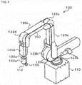
- component P is moved using a horizontal cartesian robot, but embodiments are not limited to this and various robot types are applicable, for example, a vertical cartesian robot, a cylindrical coordinate robot, or a vertical articulated robot.
- An example of a vertical articulated robot device is shown in fig. 6 .
- Component mounter 100 of fig. 6 is a vertical articulated robot provided with base 110 that is set on the floor, first to fifth links 120a to 120e, first to fifth joints 122a to 122e forming an articulated arm connected in series to base 110 and first to fifth links 120a to 120e, and drive motors that are not shown and that drive each of first to fifth joints 122a to 122e.
- base 110 that is set on the floor
- first to fifth links 120a to 120e first to fifth joints 122a to 122e forming an articulated arm connected in series to base 110 and first to fifth links 120a to 120e
- drive motors that are not shown and that drive each of first to fifth joints 122a to 122e.
- first joint 122a and fifth joint 122e are rotation joints
- second to fourth joints 122b to 122d are swing joints.
- the flowchart in fig. 3 may be performed by replacing the XYZ directions of the first embodiment with rotation directions or swing directions of first to fifth joints 122a to 122e. Because for this type of articulated robot, the vibration of the arm end section when the arm is moved is large, the invention is particularly effective.
- the present invention was described applied to component mounter 10 that moves and mounts component P on board S using a robot (XY robot 40 and head 50), but embodiments are not limited to this and may be applied to an adhesive application device that uses a robot to move adhesive to a target position and apply the adhesive, or a solder application device that uses a robot to move solder to a target position and apply the solder.
- the flowchart in fig. 3 may be performed by replacing component P with adhesive or solder respectively.
- XY robot 40 and head 50 correspond to "robot”
- the X direction or Y direction corresponds to "first direction”
- the Z direction corresponds to "second direction”.
- mark camera 56 corresponds to "imaging means”.
- acceleration sensor 55 corresponds to "acceleration sensor”.
- CPU 71 of control device 70 that performs processing of S100 of the component mounting processing shown in fig.
- CPU 71 of control device 70 that performs the processing of S120 to S140 corresponds to the "first direction movement control means”
- CPU 71 of control device 70 that performs the processing of S150 and S160 corresponds to the "vibration waveform acquiring means”
- CPU 71 of control device 70 that performs the processing of S170 to S210 corresponds to the "second direction movement control means”.
- the present invention may be applied to the industrial field of component mounters and the like.
Landscapes
- Engineering & Computer Science (AREA)
- Robotics (AREA)
- Mechanical Engineering (AREA)
- Human Computer Interaction (AREA)
- Physics & Mathematics (AREA)
- General Physics & Mathematics (AREA)
- Automation & Control Theory (AREA)
- Manipulator (AREA)
- Supply And Installment Of Electrical Components (AREA)
Applications Claiming Priority (1)
| Application Number | Priority Date | Filing Date | Title |
|---|---|---|---|
| PCT/JP2014/077165 WO2016056117A1 (ja) | 2014-10-10 | 2014-10-10 | 搬送方法および搬送装置 |
Publications (3)
| Publication Number | Publication Date |
|---|---|
| EP3205457A1 true EP3205457A1 (de) | 2017-08-16 |
| EP3205457A4 EP3205457A4 (de) | 2018-08-08 |
| EP3205457B1 EP3205457B1 (de) | 2020-07-08 |
Family
ID=55652773
Family Applications (1)
| Application Number | Title | Priority Date | Filing Date |
|---|---|---|---|
| EP14903589.1A Active EP3205457B1 (de) | 2014-10-10 | 2014-10-10 | Übertragungsverfahren und übertragungsvorrichtung |
Country Status (5)
| Country | Link |
|---|---|
| US (1) | US10456911B2 (de) |
| EP (1) | EP3205457B1 (de) |
| JP (1) | JP6472813B2 (de) |
| CN (1) | CN107073716B (de) |
| WO (1) | WO2016056117A1 (de) |
Families Citing this family (4)
| Publication number | Priority date | Publication date | Assignee | Title |
|---|---|---|---|---|
| JP6688172B2 (ja) * | 2016-06-24 | 2020-04-28 | 東京エレクトロン株式会社 | 基板処理システムおよび方法 |
| JP7305258B2 (ja) * | 2018-07-18 | 2023-07-10 | 株式会社ディスコ | 搬送システム |
| KR20210118062A (ko) * | 2019-01-25 | 2021-09-29 | 다카노 가부시키가이샤 | 화상 검사 장치 |
| CN113277314B (zh) * | 2021-05-21 | 2022-07-26 | 盐城工学院 | 基于fpga图像检测控制的板材偏移调整装置及方法 |
Family Cites Families (13)
| Publication number | Priority date | Publication date | Assignee | Title |
|---|---|---|---|---|
| JP2909331B2 (ja) * | 1992-12-02 | 1999-06-23 | 三菱重工業株式会社 | 吊荷着床制御方法 |
| JP3030555B1 (ja) | 1999-06-22 | 2000-04-10 | 株式会社ユーシン精機 | 成形品の取出装置 |
| JP2001092511A (ja) * | 1999-09-17 | 2001-04-06 | Kawasaki Heavy Ind Ltd | ロボットなどの制御ゲイン調整装置 |
| JP4390415B2 (ja) * | 1999-12-16 | 2009-12-24 | パナソニック株式会社 | ロボットの位置決め制御方法と位置決め制御装置 |
| JP3947384B2 (ja) * | 2001-10-31 | 2007-07-18 | Juki株式会社 | 部品搭載方法及び装置 |
| US6983199B2 (en) * | 2003-04-30 | 2006-01-03 | General Electric Company | Vibration measurement and recording system and method |
| JP5803189B2 (ja) | 2011-03-23 | 2015-11-04 | セイコーエプソン株式会社 | ロボット装置 |
| JP5962020B2 (ja) * | 2012-01-17 | 2016-08-03 | セイコーエプソン株式会社 | ロボット制御装置、ロボットシステム、ロボット及びロボット制御方法 |
| JP5832388B2 (ja) | 2012-07-09 | 2015-12-16 | 本田技研工業株式会社 | 作業方法及び作業装置 |
| JP5932578B2 (ja) * | 2012-09-06 | 2016-06-08 | 三菱電機株式会社 | 振動抑制方法、振動抑制装置および振動抑制機能を備えた産業用機械装置 |
| CN104669244A (zh) * | 2013-12-02 | 2015-06-03 | 精工爱普生株式会社 | 机器人 |
| JP2017087301A (ja) * | 2015-11-02 | 2017-05-25 | セイコーエプソン株式会社 | ロボット、制御装置およびロボットシステム |
| US10245724B2 (en) * | 2016-06-09 | 2019-04-02 | Shmuel Ur Innovation Ltd. | System, method and product for utilizing prediction models of an environment |
-
2014
- 2014-10-10 JP JP2016552781A patent/JP6472813B2/ja active Active
- 2014-10-10 CN CN201480082470.5A patent/CN107073716B/zh active Active
- 2014-10-10 WO PCT/JP2014/077165 patent/WO2016056117A1/ja not_active Ceased
- 2014-10-10 EP EP14903589.1A patent/EP3205457B1/de active Active
- 2014-10-10 US US15/517,292 patent/US10456911B2/en active Active
Also Published As
| Publication number | Publication date |
|---|---|
| EP3205457B1 (de) | 2020-07-08 |
| CN107073716A (zh) | 2017-08-18 |
| US10456911B2 (en) | 2019-10-29 |
| CN107073716B (zh) | 2020-03-10 |
| WO2016056117A1 (ja) | 2016-04-14 |
| JPWO2016056117A1 (ja) | 2017-07-20 |
| US20170305012A1 (en) | 2017-10-26 |
| JP6472813B2 (ja) | 2019-02-20 |
| EP3205457A4 (de) | 2018-08-08 |
Similar Documents
| Publication | Publication Date | Title |
|---|---|---|
| EP3258764B1 (de) | Ausrüstungsmontagevorrichtung und steuerungsverfahren für eine ausrüstungsmontagevorrichtung | |
| JPWO2015079740A1 (ja) | ロボットシステムおよびロボットシステムの制御方法 | |
| US11330749B2 (en) | Component-mounting device | |
| US9887111B2 (en) | Die mounting system and die mounting method | |
| EP3205457A1 (de) | Übertragungsverfahren und übertragungsvorrichtung | |
| JP4769232B2 (ja) | 実装機および部品吸着装置 | |
| JP2009016673A5 (de) | ||
| JP2017220498A (ja) | 部品実装装置及び部品実装方法 | |
| US11395449B2 (en) | Three-dimensional mounting device and three-dimensional mounting method | |
| EP3784014A1 (de) | Montageoperationsmaschine und bestätigungsverfahren | |
| US11382246B2 (en) | Substrate work system under adjustable rail spacing distance | |
| EP3713386B1 (de) | Berechnungsvorrichtung | |
| JP3927664B2 (ja) | 部品搭載装置及びその方法 | |
| US12082345B2 (en) | Component mounting machine | |
| JP6716969B2 (ja) | 実装装置 | |
| US20230413502A1 (en) | Component mounter and clamp control method | |
| JP2025121534A (ja) | ガントリ装置及び部品実装装置 | |
| JP2023067338A (ja) | 部品実装機および部品実装方法 | |
| EP3125661B1 (de) | Formmontagesystem und formmontageverfahren | |
| JP2011023684A (ja) | 電子部品実装装置 |
Legal Events
| Date | Code | Title | Description |
|---|---|---|---|
| STAA | Information on the status of an ep patent application or granted ep patent |
Free format text: STATUS: THE INTERNATIONAL PUBLICATION HAS BEEN MADE |
|
| PUAI | Public reference made under article 153(3) epc to a published international application that has entered the european phase |
Free format text: ORIGINAL CODE: 0009012 |
|
| STAA | Information on the status of an ep patent application or granted ep patent |
Free format text: STATUS: REQUEST FOR EXAMINATION WAS MADE |
|
| 17P | Request for examination filed |
Effective date: 20170330 |
|
| AK | Designated contracting states |
Kind code of ref document: A1 Designated state(s): AL AT BE BG CH CY CZ DE DK EE ES FI FR GB GR HR HU IE IS IT LI LT LU LV MC MK MT NL NO PL PT RO RS SE SI SK SM TR |
|
| AX | Request for extension of the european patent |
Extension state: BA ME |
|
| DAX | Request for extension of the european patent (deleted) | ||
| REG | Reference to a national code |
Ref country code: DE Ref legal event code: R079 Ref document number: 602014067618 Country of ref document: DE Free format text: PREVIOUS MAIN CLASS: B25J0013000000 Ipc: B25J0009160000 |
|
| A4 | Supplementary search report drawn up and despatched |
Effective date: 20180706 |
|
| RIC1 | Information provided on ipc code assigned before grant |
Ipc: G05D 19/02 20060101ALN20180702BHEP Ipc: B25J 9/16 20060101AFI20180702BHEP |
|
| RAP1 | Party data changed (applicant data changed or rights of an application transferred) |
Owner name: FUJI CORPORATION |
|
| RIN1 | Information on inventor provided before grant (corrected) |
Inventor name: NAGATA, RYO Inventor name: FUJITA, MASATOSHI |
|
| STAA | Information on the status of an ep patent application or granted ep patent |
Free format text: STATUS: EXAMINATION IS IN PROGRESS |
|
| 17Q | First examination report despatched |
Effective date: 20190624 |
|
| GRAP | Despatch of communication of intention to grant a patent |
Free format text: ORIGINAL CODE: EPIDOSNIGR1 |
|
| STAA | Information on the status of an ep patent application or granted ep patent |
Free format text: STATUS: GRANT OF PATENT IS INTENDED |
|
| INTG | Intention to grant announced |
Effective date: 20200311 |
|
| GRAS | Grant fee paid |
Free format text: ORIGINAL CODE: EPIDOSNIGR3 |
|
| GRAA | (expected) grant |
Free format text: ORIGINAL CODE: 0009210 |
|
| STAA | Information on the status of an ep patent application or granted ep patent |
Free format text: STATUS: THE PATENT HAS BEEN GRANTED |
|
| AK | Designated contracting states |
Kind code of ref document: B1 Designated state(s): AL AT BE BG CH CY CZ DE DK EE ES FI FR GB GR HR HU IE IS IT LI LT LU LV MC MK MT NL NO PL PT RO RS SE SI SK SM TR |
|
| REG | Reference to a national code |
Ref country code: CH Ref legal event code: EP Ref country code: AT Ref legal event code: REF Ref document number: 1287955 Country of ref document: AT Kind code of ref document: T Effective date: 20200715 |
|
| REG | Reference to a national code |
Ref country code: DE Ref legal event code: R096 Ref document number: 602014067618 Country of ref document: DE |
|
| REG | Reference to a national code |
Ref country code: IE Ref legal event code: FG4D |
|
| REG | Reference to a national code |
Ref country code: LT Ref legal event code: MG4D |
|
| REG | Reference to a national code |
Ref country code: AT Ref legal event code: MK05 Ref document number: 1287955 Country of ref document: AT Kind code of ref document: T Effective date: 20200708 |
|
| REG | Reference to a national code |
Ref country code: NL Ref legal event code: MP Effective date: 20200708 |
|
| PG25 | Lapsed in a contracting state [announced via postgrant information from national office to epo] |
Ref country code: LT Free format text: LAPSE BECAUSE OF FAILURE TO SUBMIT A TRANSLATION OF THE DESCRIPTION OR TO PAY THE FEE WITHIN THE PRESCRIBED TIME-LIMIT Effective date: 20200708 Ref country code: HR Free format text: LAPSE BECAUSE OF FAILURE TO SUBMIT A TRANSLATION OF THE DESCRIPTION OR TO PAY THE FEE WITHIN THE PRESCRIBED TIME-LIMIT Effective date: 20200708 Ref country code: PT Free format text: LAPSE BECAUSE OF FAILURE TO SUBMIT A TRANSLATION OF THE DESCRIPTION OR TO PAY THE FEE WITHIN THE PRESCRIBED TIME-LIMIT Effective date: 20201109 Ref country code: FI Free format text: LAPSE BECAUSE OF FAILURE TO SUBMIT A TRANSLATION OF THE DESCRIPTION OR TO PAY THE FEE WITHIN THE PRESCRIBED TIME-LIMIT Effective date: 20200708 Ref country code: SE Free format text: LAPSE BECAUSE OF FAILURE TO SUBMIT A TRANSLATION OF THE DESCRIPTION OR TO PAY THE FEE WITHIN THE PRESCRIBED TIME-LIMIT Effective date: 20200708 Ref country code: ES Free format text: LAPSE BECAUSE OF FAILURE TO SUBMIT A TRANSLATION OF THE DESCRIPTION OR TO PAY THE FEE WITHIN THE PRESCRIBED TIME-LIMIT Effective date: 20200708 Ref country code: GR Free format text: LAPSE BECAUSE OF FAILURE TO SUBMIT A TRANSLATION OF THE DESCRIPTION OR TO PAY THE FEE WITHIN THE PRESCRIBED TIME-LIMIT Effective date: 20201009 Ref country code: NO Free format text: LAPSE BECAUSE OF FAILURE TO SUBMIT A TRANSLATION OF THE DESCRIPTION OR TO PAY THE FEE WITHIN THE PRESCRIBED TIME-LIMIT Effective date: 20201008 Ref country code: BG Free format text: LAPSE BECAUSE OF FAILURE TO SUBMIT A TRANSLATION OF THE DESCRIPTION OR TO PAY THE FEE WITHIN THE PRESCRIBED TIME-LIMIT Effective date: 20201008 Ref country code: AT Free format text: LAPSE BECAUSE OF FAILURE TO SUBMIT A TRANSLATION OF THE DESCRIPTION OR TO PAY THE FEE WITHIN THE PRESCRIBED TIME-LIMIT Effective date: 20200708 |
|
| PG25 | Lapsed in a contracting state [announced via postgrant information from national office to epo] |
Ref country code: RS Free format text: LAPSE BECAUSE OF FAILURE TO SUBMIT A TRANSLATION OF THE DESCRIPTION OR TO PAY THE FEE WITHIN THE PRESCRIBED TIME-LIMIT Effective date: 20200708 Ref country code: PL Free format text: LAPSE BECAUSE OF FAILURE TO SUBMIT A TRANSLATION OF THE DESCRIPTION OR TO PAY THE FEE WITHIN THE PRESCRIBED TIME-LIMIT Effective date: 20200708 Ref country code: LV Free format text: LAPSE BECAUSE OF FAILURE TO SUBMIT A TRANSLATION OF THE DESCRIPTION OR TO PAY THE FEE WITHIN THE PRESCRIBED TIME-LIMIT Effective date: 20200708 Ref country code: IS Free format text: LAPSE BECAUSE OF FAILURE TO SUBMIT A TRANSLATION OF THE DESCRIPTION OR TO PAY THE FEE WITHIN THE PRESCRIBED TIME-LIMIT Effective date: 20201108 |
|
| PG25 | Lapsed in a contracting state [announced via postgrant information from national office to epo] |
Ref country code: NL Free format text: LAPSE BECAUSE OF FAILURE TO SUBMIT A TRANSLATION OF THE DESCRIPTION OR TO PAY THE FEE WITHIN THE PRESCRIBED TIME-LIMIT Effective date: 20200708 |
|
| REG | Reference to a national code |
Ref country code: DE Ref legal event code: R097 Ref document number: 602014067618 Country of ref document: DE |
|
| PG25 | Lapsed in a contracting state [announced via postgrant information from national office to epo] |
Ref country code: IT Free format text: LAPSE BECAUSE OF FAILURE TO SUBMIT A TRANSLATION OF THE DESCRIPTION OR TO PAY THE FEE WITHIN THE PRESCRIBED TIME-LIMIT Effective date: 20200708 Ref country code: DK Free format text: LAPSE BECAUSE OF FAILURE TO SUBMIT A TRANSLATION OF THE DESCRIPTION OR TO PAY THE FEE WITHIN THE PRESCRIBED TIME-LIMIT Effective date: 20200708 Ref country code: CZ Free format text: LAPSE BECAUSE OF FAILURE TO SUBMIT A TRANSLATION OF THE DESCRIPTION OR TO PAY THE FEE WITHIN THE PRESCRIBED TIME-LIMIT Effective date: 20200708 Ref country code: SM Free format text: LAPSE BECAUSE OF FAILURE TO SUBMIT A TRANSLATION OF THE DESCRIPTION OR TO PAY THE FEE WITHIN THE PRESCRIBED TIME-LIMIT Effective date: 20200708 Ref country code: RO Free format text: LAPSE BECAUSE OF FAILURE TO SUBMIT A TRANSLATION OF THE DESCRIPTION OR TO PAY THE FEE WITHIN THE PRESCRIBED TIME-LIMIT Effective date: 20200708 Ref country code: EE Free format text: LAPSE BECAUSE OF FAILURE TO SUBMIT A TRANSLATION OF THE DESCRIPTION OR TO PAY THE FEE WITHIN THE PRESCRIBED TIME-LIMIT Effective date: 20200708 |
|
| PLBE | No opposition filed within time limit |
Free format text: ORIGINAL CODE: 0009261 |
|
| STAA | Information on the status of an ep patent application or granted ep patent |
Free format text: STATUS: NO OPPOSITION FILED WITHIN TIME LIMIT |
|
| PG25 | Lapsed in a contracting state [announced via postgrant information from national office to epo] |
Ref country code: AL Free format text: LAPSE BECAUSE OF FAILURE TO SUBMIT A TRANSLATION OF THE DESCRIPTION OR TO PAY THE FEE WITHIN THE PRESCRIBED TIME-LIMIT Effective date: 20200708 |
|
| REG | Reference to a national code |
Ref country code: CH Ref legal event code: PL |
|
| 26N | No opposition filed |
Effective date: 20210409 |
|
| GBPC | Gb: european patent ceased through non-payment of renewal fee |
Effective date: 20201010 |
|
| PG25 | Lapsed in a contracting state [announced via postgrant information from national office to epo] |
Ref country code: MC Free format text: LAPSE BECAUSE OF FAILURE TO SUBMIT A TRANSLATION OF THE DESCRIPTION OR TO PAY THE FEE WITHIN THE PRESCRIBED TIME-LIMIT Effective date: 20200708 Ref country code: LU Free format text: LAPSE BECAUSE OF NON-PAYMENT OF DUE FEES Effective date: 20201010 Ref country code: SK Free format text: LAPSE BECAUSE OF FAILURE TO SUBMIT A TRANSLATION OF THE DESCRIPTION OR TO PAY THE FEE WITHIN THE PRESCRIBED TIME-LIMIT Effective date: 20200708 |
|
| REG | Reference to a national code |
Ref country code: BE Ref legal event code: MM Effective date: 20201031 |
|
| PG25 | Lapsed in a contracting state [announced via postgrant information from national office to epo] |
Ref country code: FR Free format text: LAPSE BECAUSE OF NON-PAYMENT OF DUE FEES Effective date: 20201031 |
|
| PG25 | Lapsed in a contracting state [announced via postgrant information from national office to epo] |
Ref country code: SI Free format text: LAPSE BECAUSE OF FAILURE TO SUBMIT A TRANSLATION OF THE DESCRIPTION OR TO PAY THE FEE WITHIN THE PRESCRIBED TIME-LIMIT Effective date: 20200708 Ref country code: GB Free format text: LAPSE BECAUSE OF NON-PAYMENT OF DUE FEES Effective date: 20201010 Ref country code: LI Free format text: LAPSE BECAUSE OF NON-PAYMENT OF DUE FEES Effective date: 20201031 Ref country code: CH Free format text: LAPSE BECAUSE OF NON-PAYMENT OF DUE FEES Effective date: 20201031 Ref country code: BE Free format text: LAPSE BECAUSE OF NON-PAYMENT OF DUE FEES Effective date: 20201031 |
|
| PG25 | Lapsed in a contracting state [announced via postgrant information from national office to epo] |
Ref country code: IE Free format text: LAPSE BECAUSE OF NON-PAYMENT OF DUE FEES Effective date: 20201010 |
|
| PG25 | Lapsed in a contracting state [announced via postgrant information from national office to epo] |
Ref country code: TR Free format text: LAPSE BECAUSE OF FAILURE TO SUBMIT A TRANSLATION OF THE DESCRIPTION OR TO PAY THE FEE WITHIN THE PRESCRIBED TIME-LIMIT Effective date: 20200708 Ref country code: MT Free format text: LAPSE BECAUSE OF FAILURE TO SUBMIT A TRANSLATION OF THE DESCRIPTION OR TO PAY THE FEE WITHIN THE PRESCRIBED TIME-LIMIT Effective date: 20200708 Ref country code: CY Free format text: LAPSE BECAUSE OF FAILURE TO SUBMIT A TRANSLATION OF THE DESCRIPTION OR TO PAY THE FEE WITHIN THE PRESCRIBED TIME-LIMIT Effective date: 20200708 |
|
| PG25 | Lapsed in a contracting state [announced via postgrant information from national office to epo] |
Ref country code: MK Free format text: LAPSE BECAUSE OF FAILURE TO SUBMIT A TRANSLATION OF THE DESCRIPTION OR TO PAY THE FEE WITHIN THE PRESCRIBED TIME-LIMIT Effective date: 20200708 |
|
| P01 | Opt-out of the competence of the unified patent court (upc) registered |
Effective date: 20230328 |
|
| PGFP | Annual fee paid to national office [announced via postgrant information from national office to epo] |
Ref country code: DE Payment date: 20250902 Year of fee payment: 12 |