EP3205477A1 - Machine et procédé d'installation d'une feuille de revêtement sur des sections d'extrémité soudées d'un pipeline - Google Patents
Machine et procédé d'installation d'une feuille de revêtement sur des sections d'extrémité soudées d'un pipeline Download PDFInfo
- Publication number
- EP3205477A1 EP3205477A1 EP16155584.2A EP16155584A EP3205477A1 EP 3205477 A1 EP3205477 A1 EP 3205477A1 EP 16155584 A EP16155584 A EP 16155584A EP 3205477 A1 EP3205477 A1 EP 3205477A1
- Authority
- EP
- European Patent Office
- Prior art keywords
- pipe
- sheet
- roller
- mat
- machine according
- Prior art date
- Legal status (The legal status is an assumption and is not a legal conclusion. Google has not performed a legal analysis and makes no representation as to the accuracy of the status listed.)
- Withdrawn
Links
- 238000000576 coating method Methods 0.000 title claims abstract description 46
- 239000011248 coating agent Substances 0.000 title claims abstract description 45
- 238000000034 method Methods 0.000 title claims description 16
- 239000006260 foam Substances 0.000 claims description 11
- 238000010438 heat treatment Methods 0.000 claims description 10
- 229920002379 silicone rubber Polymers 0.000 claims description 6
- 239000004945 silicone rubber Substances 0.000 claims description 6
- 239000011324 bead Substances 0.000 claims description 5
- 239000002131 composite material Substances 0.000 claims description 5
- 238000003825 pressing Methods 0.000 claims description 5
- XUIMIQQOPSSXEZ-UHFFFAOYSA-N Silicon Chemical compound [Si] XUIMIQQOPSSXEZ-UHFFFAOYSA-N 0.000 claims description 3
- 229910052710 silicon Inorganic materials 0.000 claims description 3
- 239000010703 silicon Substances 0.000 claims description 3
- 238000011065 in-situ storage Methods 0.000 claims description 2
- 239000004033 plastic Substances 0.000 claims description 2
- 229920003023 plastic Polymers 0.000 claims description 2
- 230000001105 regulatory effect Effects 0.000 claims description 2
- 239000000155 melt Substances 0.000 claims 1
- -1 Polypropylene Polymers 0.000 description 9
- 238000005096 rolling process Methods 0.000 description 8
- 229920003002 synthetic resin Polymers 0.000 description 7
- 239000000057 synthetic resin Substances 0.000 description 7
- 239000004698 Polyethylene Substances 0.000 description 6
- 239000004743 Polypropylene Substances 0.000 description 6
- 229920000573 polyethylene Polymers 0.000 description 6
- 229920001155 polypropylene Polymers 0.000 description 6
- 230000007797 corrosion Effects 0.000 description 5
- 238000005260 corrosion Methods 0.000 description 5
- 239000000463 material Substances 0.000 description 5
- 238000003466 welding Methods 0.000 description 4
- 230000033228 biological regulation Effects 0.000 description 3
- 230000004927 fusion Effects 0.000 description 3
- 229920001343 polytetrafluoroethylene Polymers 0.000 description 3
- 239000004810 polytetrafluoroethylene Substances 0.000 description 3
- 229920001169 thermoplastic Polymers 0.000 description 3
- 239000004593 Epoxy Substances 0.000 description 2
- 239000000853 adhesive Substances 0.000 description 2
- 230000001070 adhesive effect Effects 0.000 description 2
- 239000007788 liquid Substances 0.000 description 2
- 239000011253 protective coating Substances 0.000 description 2
- 238000003860 storage Methods 0.000 description 2
- 239000004416 thermosoftening plastic Substances 0.000 description 2
- 229910000831 Steel Inorganic materials 0.000 description 1
- 238000005270 abrasive blasting Methods 0.000 description 1
- 230000005540 biological transmission Effects 0.000 description 1
- 238000010276 construction Methods 0.000 description 1
- 229920001577 copolymer Polymers 0.000 description 1
- 230000009977 dual effect Effects 0.000 description 1
- 238000009413 insulation Methods 0.000 description 1
- 230000010354 integration Effects 0.000 description 1
- 238000004519 manufacturing process Methods 0.000 description 1
- 238000002844 melting Methods 0.000 description 1
- 230000008018 melting Effects 0.000 description 1
- 239000000203 mixture Substances 0.000 description 1
- 239000012768 molten material Substances 0.000 description 1
- 229920000642 polymer Polymers 0.000 description 1
- 239000000843 powder Substances 0.000 description 1
- 238000002360 preparation method Methods 0.000 description 1
- 230000001681 protective effect Effects 0.000 description 1
- 238000003908 quality control method Methods 0.000 description 1
- 238000009877 rendering Methods 0.000 description 1
- 239000011343 solid material Substances 0.000 description 1
- 230000006641 stabilisation Effects 0.000 description 1
- 238000011105 stabilization Methods 0.000 description 1
- 239000010959 steel Substances 0.000 description 1
- 239000000758 substrate Substances 0.000 description 1
- 230000001360 synchronised effect Effects 0.000 description 1
- 230000000930 thermomechanical effect Effects 0.000 description 1
- 239000012815 thermoplastic material Substances 0.000 description 1
Images


Classifications
-
- B—PERFORMING OPERATIONS; TRANSPORTING
- B29—WORKING OF PLASTICS; WORKING OF SUBSTANCES IN A PLASTIC STATE IN GENERAL
- B29C—SHAPING OR JOINING OF PLASTICS; SHAPING OF MATERIAL IN A PLASTIC STATE, NOT OTHERWISE PROVIDED FOR; AFTER-TREATMENT OF THE SHAPED PRODUCTS, e.g. REPAIRING
- B29C63/00—Lining or sheathing, i.e. applying preformed layers or sheathings of plastics; Apparatus therefor
- B29C63/0065—Heat treatment
-
- B—PERFORMING OPERATIONS; TRANSPORTING
- B29—WORKING OF PLASTICS; WORKING OF SUBSTANCES IN A PLASTIC STATE IN GENERAL
- B29C—SHAPING OR JOINING OF PLASTICS; SHAPING OF MATERIAL IN A PLASTIC STATE, NOT OTHERWISE PROVIDED FOR; AFTER-TREATMENT OF THE SHAPED PRODUCTS, e.g. REPAIRING
- B29C63/00—Lining or sheathing, i.e. applying preformed layers or sheathings of plastics; Apparatus therefor
- B29C63/02—Lining or sheathing, i.e. applying preformed layers or sheathings of plastics; Apparatus therefor using sheet or web-like material
- B29C63/024—Lining or sheathing, i.e. applying preformed layers or sheathings of plastics; Apparatus therefor using sheet or web-like material the sheet or web-like material being supported by a moving carriage
-
- B—PERFORMING OPERATIONS; TRANSPORTING
- B29—WORKING OF PLASTICS; WORKING OF SUBSTANCES IN A PLASTIC STATE IN GENERAL
- B29C—SHAPING OR JOINING OF PLASTICS; SHAPING OF MATERIAL IN A PLASTIC STATE, NOT OTHERWISE PROVIDED FOR; AFTER-TREATMENT OF THE SHAPED PRODUCTS, e.g. REPAIRING
- B29C63/00—Lining or sheathing, i.e. applying preformed layers or sheathings of plastics; Apparatus therefor
- B29C63/02—Lining or sheathing, i.e. applying preformed layers or sheathings of plastics; Apparatus therefor using sheet or web-like material
- B29C63/04—Lining or sheathing, i.e. applying preformed layers or sheathings of plastics; Apparatus therefor using sheet or web-like material by folding, winding, bending or the like
- B29C63/06—Lining or sheathing, i.e. applying preformed layers or sheathings of plastics; Apparatus therefor using sheet or web-like material by folding, winding, bending or the like around tubular articles
-
- F—MECHANICAL ENGINEERING; LIGHTING; HEATING; WEAPONS; BLASTING
- F16—ENGINEERING ELEMENTS AND UNITS; GENERAL MEASURES FOR PRODUCING AND MAINTAINING EFFECTIVE FUNCTIONING OF MACHINES OR INSTALLATIONS; THERMAL INSULATION IN GENERAL
- F16L—PIPES; JOINTS OR FITTINGS FOR PIPES; SUPPORTS FOR PIPES, CABLES OR PROTECTIVE TUBING; MEANS FOR THERMAL INSULATION IN GENERAL
- F16L58/00—Protection of pipes or pipe fittings against corrosion or incrustation
- F16L58/18—Protection of pipes or pipe fittings against corrosion or incrustation specially adapted for pipe fittings
- F16L58/181—Protection of pipes or pipe fittings against corrosion or incrustation specially adapted for pipe fittings for non-disconnectable pipe joints
-
- B—PERFORMING OPERATIONS; TRANSPORTING
- B29—WORKING OF PLASTICS; WORKING OF SUBSTANCES IN A PLASTIC STATE IN GENERAL
- B29C—SHAPING OR JOINING OF PLASTICS; SHAPING OF MATERIAL IN A PLASTIC STATE, NOT OTHERWISE PROVIDED FOR; AFTER-TREATMENT OF THE SHAPED PRODUCTS, e.g. REPAIRING
- B29C63/00—Lining or sheathing, i.e. applying preformed layers or sheathings of plastics; Apparatus therefor
- B29C63/0004—Component parts, details or accessories; Auxiliary operations
- B29C63/0013—Removing old coatings
-
- B—PERFORMING OPERATIONS; TRANSPORTING
- B29—WORKING OF PLASTICS; WORKING OF SUBSTANCES IN A PLASTIC STATE IN GENERAL
- B29C—SHAPING OR JOINING OF PLASTICS; SHAPING OF MATERIAL IN A PLASTIC STATE, NOT OTHERWISE PROVIDED FOR; AFTER-TREATMENT OF THE SHAPED PRODUCTS, e.g. REPAIRING
- B29C63/00—Lining or sheathing, i.e. applying preformed layers or sheathings of plastics; Apparatus therefor
- B29C63/02—Lining or sheathing, i.e. applying preformed layers or sheathings of plastics; Apparatus therefor using sheet or web-like material
- B29C63/04—Lining or sheathing, i.e. applying preformed layers or sheathings of plastics; Apparatus therefor using sheet or web-like material by folding, winding, bending or the like
- B29C63/12—Lining or sheathing, i.e. applying preformed layers or sheathings of plastics; Apparatus therefor using sheet or web-like material by folding, winding, bending or the like by winding spirally
- B29C63/14—Lining or sheathing, i.e. applying preformed layers or sheathings of plastics; Apparatus therefor using sheet or web-like material by folding, winding, bending or the like by winding spirally around tubular articles
- B29C63/145—Lining or sheathing, i.e. applying preformed layers or sheathings of plastics; Apparatus therefor using sheet or web-like material by folding, winding, bending or the like by winding spirally around tubular articles the tubular articles being mounted on transfer means
-
- F—MECHANICAL ENGINEERING; LIGHTING; HEATING; WEAPONS; BLASTING
- F16—ENGINEERING ELEMENTS AND UNITS; GENERAL MEASURES FOR PRODUCING AND MAINTAINING EFFECTIVE FUNCTIONING OF MACHINES OR INSTALLATIONS; THERMAL INSULATION IN GENERAL
- F16L—PIPES; JOINTS OR FITTINGS FOR PIPES; SUPPORTS FOR PIPES, CABLES OR PROTECTIVE TUBING; MEANS FOR THERMAL INSULATION IN GENERAL
- F16L13/00—Non-disconnectable pipe joints, e.g. soldered, adhesive, or caulked joints
- F16L13/02—Welded joints
- F16L13/0254—Welded joints the pipes having an internal or external coating
- F16L13/0272—Welded joints the pipes having an internal or external coating having an external coating
-
- Y—GENERAL TAGGING OF NEW TECHNOLOGICAL DEVELOPMENTS; GENERAL TAGGING OF CROSS-SECTIONAL TECHNOLOGIES SPANNING OVER SEVERAL SECTIONS OF THE IPC; TECHNICAL SUBJECTS COVERED BY FORMER USPC CROSS-REFERENCE ART COLLECTIONS [XRACs] AND DIGESTS
- Y10—TECHNICAL SUBJECTS COVERED BY FORMER USPC
- Y10T—TECHNICAL SUBJECTS COVERED BY FORMER US CLASSIFICATION
- Y10T156/00—Adhesive bonding and miscellaneous chemical manufacture
- Y10T156/12—Surface bonding means and/or assembly means with cutting, punching, piercing, severing or tearing
- Y10T156/1348—Work traversing type
-
- Y—GENERAL TAGGING OF NEW TECHNOLOGICAL DEVELOPMENTS; GENERAL TAGGING OF CROSS-SECTIONAL TECHNOLOGIES SPANNING OVER SEVERAL SECTIONS OF THE IPC; TECHNICAL SUBJECTS COVERED BY FORMER USPC CROSS-REFERENCE ART COLLECTIONS [XRACs] AND DIGESTS
- Y10—TECHNICAL SUBJECTS COVERED BY FORMER USPC
- Y10T—TECHNICAL SUBJECTS COVERED BY FORMER US CLASSIFICATION
- Y10T156/00—Adhesive bonding and miscellaneous chemical manufacture
- Y10T156/17—Surface bonding means and/or assemblymeans with work feeding or handling means
- Y10T156/1788—Work traversing type and/or means applying work to wall or static structure
Definitions
- the present invention relates generally to machines providing a protective synthetic resin coating and to methods of installing such a coating to welded end sections of pipeline.
- FC factory coating
- Three Layer Coating is a complete corrosion protection system composed of three elements (layers) working together.
- the first layer is a fusion bonded epoxy (FBE) coating.
- the second layer is a chemically modified PP or PE adhesive.
- the third layer is a co-polymer outer layer in varying thicknesses, usually several millimeters thick. Combined as a system these elements work together to protect the pipe from undesirable corrosion, wear and impact damage.
- a compatible field joint coating system for 3LPP or 3LPE coated pipelines comprising a heat assisted helically wrapped tape application system from US7243697 , is known prior art.
- This system utilizes existing equipment for abrasive blasting or surface preparation and application of a first fusion bonded epoxy (FBE) layer, then covered with chemically modified polypropylene (CMPP) or polyethylene (CMPE) dual powder second layer.
- FBE first fusion bonded epoxy
- CMPP chemically modified polypropylene
- CMPE polyethylene
- a third layer is immediately applied by the machine helically wrapping applied polypropylene (PP) or polyethylene (PE) tape, where the tape overlaps each preceding wrap and is also overlapping the factory coating to create a continuous coating.
- PP polypropylene
- PE polyethylene
- Another joint coating is provided by longitudinal sheet wrap which involves wrapping a sheet of thermoplastic material around the pipe.
- longitudinal sheet wrap which involves wrapping a sheet of thermoplastic material around the pipe.
- US-6440245 it is known a ready-to-use multi-layer coextruded sheathing comprising at least the 3 layers system in a single sheathing.
- the multi-layer sheathing is previously heated and then transferred with a roller having a larger diameter than the pipe, around the pipe.
- the applicator roller needs to be at least the pipe diameter or bigger. This feature restrict the ability of the machine to coat large diameters pipes, when line pipes are already landed and welded over kilometers, because, it will be no more possible to change the line pipe height relative to the ground.
- a machine for coating a pipe joint with a cylindrically wound unheated sheet of synthetic resin on the joint that is already coated with 2 layers includes a mounting frame mountable on adjacent coated sections of the pipeline to span the pipe joint being coated and a transport carriage rotatably movable on the mounting frame to move circumferentially about the pipe joint.
- a storage reel is mounted on the transport carriage for storing a supply of the unheated sheet of synthetic resin to be wound about the pipe joint.
- An applicator roller is mounted on the carriage frame and applies the unheated sheet of synthetic resin from the storage reel onto the pipe joint as the transport carriage moves about the circumference of the pipe joint.
- a heater is mounted on the transport carriage to heat the applied unheated sheet of synthetic resin after it has been applied to the pipe joint, to preheat the substrate and the factory coating overlap area, the newly applied unheated sheet of synthetic resin material, and the previously applied material on subsequent revolutions of the applicator.
- This machine has several drawbacks because it needs to develop a roller with specific heating capabilities for each type of synthetic resin sheet.
- This system needs to apply the sheet just after having coated the first two layer of the 3LPP or 3LPE system. This feature is not allowing intermediate control of the first two layers, and in rendering temperature control very difficult due to inevitable change in the production line speed. And the main drawback is the risk of having air trapped between each successive layers of wrapped sheet material provided for an efficient protective coating.
- An object of the invention is a machine for coating a pipe, especially a pipe joint formed after welding together stub ends of coated sections of pipe for a pipeline, the coating comprising a sheet applied circumferentially around the pipe, the machine comprising:
- the present invention achieves a better adhesion of the sheet wrapped around the pipe, the sheet being the last third layer of the 3LPP or 3LPE system, with high quality control of the former 2 layers.
- the machine and process of the invention achieves an excellent adhesion to the factory coating and the former 2 layers system, for example an adhesion that may withstand strength forces over 600 N/25mm, and also excellent adhesion of the overlapped ends of the sheet that may withstand strength forces superior to 600 N/25mm.
- the mat pusher may comprise an out feed table movable between a closed position and a retracted position, such that the roller has room to support the mat when the out feed table is in the retracted position.
- This feature allows the roller to press the mat supporting a sheet against the pipe joint at a location distant from the overlapping ends of the sheet.
- the mat pusher may comprise alignment means in order to adjust the orientation of the mat supporting a sheet perpendicularly to the pipe axis.
- the mat pusher may also be adjusted laterally to perfectly match the annular zone of the pipe joint to be covered.
- the mat may be a composite carrier comprising a foam layer covered by a silicone rubber profiled surface, where preferably the foam layer is an open cell silicon foam layer larger and the profiled surface is a silicone rubber film, such that the foam layer is larger than the profiled surface.
- the silicone rubber film may be a PTFE (polytetrafluoroethylene) film.
- the profiled surface of the mat may comprise two longitudinal parallel beads, configured to adjust to both lateral sides of the annular weld cap. Such conformance to the weld cap help preventing air trapped bulbs on both side of the weld cap at the interface between the pipe and the sheet, and also avoid burn through problem.
- the profiled surface may also comprise two additional longitudinal parallel beads, configured to adjust to both lateral edges of a factory coating of the pipe joint.
- any profile of foam can be conceived specifically developed in shape, and hardness to accommodate a multiplicity of joint profiles.
- the roller is preferably movable both clockwise and counterclockwise with reverse rotation being monitored and achievable at any location around the pipe.
- the roller is cylindrical in shape with parallel generatrices. Moreover, based on the concept of one size fits all, a single roller size may be used for all pipe from 50.8 mm (2") to 304.8 mm (12"), even 350,6 mm (14") pipe outer diameter. The outer diameter of the cylindrical roller may be 300 mm or less.
- the machine according to the invention may comprise pipe supports on either side of the roller in order to limit the movement of the pipe while the roller is applied against the pipe.
- the mounting frame may comprise two end plates secured together, both end plates having a hole to accommodate the pipe, and the transport carriage comprises two guide rings both rotatable around the pipe, such that each guide ring is mounted on a respective end plate of the two end plates
- guide rings are motorized, one of the guide rings may transmit the movement to the other guide ring by an axle and means of a motorized cinematic chain.
- the guide rings may comprise counterweights to balance the weight of the roller.
- the roller may comprise adjustment means to be moved radially relatively to the pipe in order to adjust the pressure, and adapt to the eccentricity and ovality of the pipe. Adjustment means may be defined prior to pressing the roller against the pipe body, prior to each new cycle. Additionally the transport carriage may comprise a pipe diameter compensation cylinder to adjust the axis of rotation of the roller.
- the push system may be a low friction air cylinder powered and regulated in function with the angular location of the roller around the pipe. Further, by incorporating a counter balance, the effective control of the pressure developed by the push system is optimized.
- the machine may comprise an overlap heater in order to heat locally the overlapping area of the overlapping ends of the sheet transferred to the pipe, such as for instance infrared resistances, hot air, heating blade or wheel.
- an overlap heater may be adjusted around the pipe over an angle of +/-30° around the apex of the pipe, preferably at +/-10° to the apex.
- the machine according to the invention may comprise a preliminary circumferential heater to heat the pipe field joint profile at a previous stage, prior to translating the heated pipe to the next station where the machine will ensure transfer of the sheet to the heated pipe.
- the machine may comprise an oven configured to heat the sheet in a heating station such that a feed table of the heating station provides the mat pusher with a heated sheet on a mat.
- This heating station allows a controlled process where temperatures and times are under control.
- Another object of the invention is a method for the anticorrosive protection in situ of an annular area of a pipe, wherein the method includes the stages of:
- the method may comprise a prior stage where the pipe to be coated is previously circumferentially heated to a temperature distinct from the heated sheet temperature. This ensures precise, and defined application temperature is achieved.
- a gradient of temperature formed within the heated sheet in order to obtain lateral location with the factory coating at a higher temperature than the center, both lateral location being intended to apply against those chamfered coated sections of pipe, while the center is applied against a primary coating, for example the primary coating being a 2 layer system previously placed on the annular area.
- This thermal regulation enhances adhesion to factory coating.
- the sheet may be heated to melt point, so that a semi-molten web of plastic is applied to the pipe. This improves how air is expelled from the interface between pipe and polymer coating. Thus a better adhesion with less pressure is achieved and protection of the weld cap is enhanced.
- the first part of the sheet placed in contact with the pipe may be away from overlapping ends of the sheet, especially biased towards the midpoint but not necessarily at the midpoint.
- thermoplastic sheet applied circumferentially around a pipe, for example with a machine according to the invention, wherein the sheet has chamfered overlapping ends, in order to limit the thickness of the applied sheet where those chamfered overlapping-ends are overlapping.
- the sheet may have a maximum thickness along a circumferential central line that is intended to be applied against an annular weld cap of the pipe joint.
- the invention can be used to add additional outer sheets, to form a composite of two, three or more overlaying sheets laminated and bonded together, each additional sheet being of the same or differing material, so as to improve the functional properties of the coating.
- Figure 1 show a machine 1 according to the invention mounted around two pipes P1 and P2 welded together.
- a circumferential heater 2 is placed next to machine 1. Pipes first go through the circumferential heater 2 prior being within machine 1.
- Machine 1 is dedicated to coating a pipe with a sheet 20 to apply circumferentially around the pipe.
- the principle of the invention is to wrap a pre-cut sheet around at least the circumference of a field joint FJ formed between pipes P1 and P2.
- the field joint FJ schematically represented on Figure 2 is obtained by any suitable welding process, and comprises a weld cap WC.
- the weld cap WC may also be covered with a primary coating PC of the field joint FJ.
- Pipes P1 and P2 are externally covered by a factory coating, respectively FC1 and FC2. Prior to the welding of P1 together with P2, factory coating is partially removed on both pipes in order to present naked end pipe sections able to be welded together. For example, factory coating is removed along respectively a chamfered section CS1 and CS2.
- the weld cap is covered by a primary coating PC.
- the aim of the invention is to wrap the sheet (or final layer FL) at least all around the weld cap WC, better all around the primary coating PC, and even better all around the primary coating PC and if existing remaining naked pipe section of P1 and P2, and also around at least part of both chamfered section CS1 and CS2 of respective factory coating FC1 and FC2. As shown on Figure 2 , the sheet 20 is fully covering CS1, FJ and CS2.
- the sheet 20 is pushed onto the pipe with pressure so that the sheet adheres to the primary coating PC. Adhesion is promoted by pre-heating the sheet 20 and the field joint, especially all the primary coating PC, sufficient to ensure fusion through localized and controlled melting, consequently satisfying the minimum specified adhesive force.
- Machine 1 comprises a system for supporting the pipe, such system comprises hollow pipe frames 3 and 4 and holding means 5 to hold the pipe on either side of the location to be coated.
- the function of the system for supporting the pipe is to limit the movement of the pipe while the sheet 20 is applied around the pipe.
- the system is adjustable for different ranges of pipe diameters.
- Holding means 5 comprise equally spaced radial pushers.
- holding means 5 may comprise three 120° spaced radially oriented pipe supports.
- Machine 1 comprises a sheet application roller 6 freely rotatable around an axle maintained between two guide rings, respectively 7 and 8.
- Guide rings 7 and 8 are rotatable relative to their respective pipe frame 3 and 4.
- a motor 9 is rotating a pinion 10 engaged via a drive system with the guide ring 8.
- Stabilization rollers 11 are ensuring vertical (11 a) and lateral (11b) position of the guide ring relative to its pipe frame when rotating. Rotation of both guide rings 7 and 8 are synchronized. For example, motorized transmission of the movement of guide ring 7 is transmitted to guide ring 8 with motorized cinematic chain (not shown).
- Axle of the roller is maintained by a pivot bearing 12 in a controlled contact position with the pipe, due to a balance with load balance weights 13, and low friction air cylinder management 14.
- Position of the axle of the roller is managed through a pipe diameter compensation push system 15, able to adapt to a slight eccentricity and ovality of the pipe in machine 1.
- Roller being located at one location around the guide rings.
- Guide rings are both equipped with counter balance weights 16.
- Guide rings, and consequently the roller is able to roll either clockwise or counterclockwise around the pipe.
- Machine 1 also comprises an oven 17 to heat the sheet prior to being transferred to the pipe.
- the oven 17 may be an infra-red heating system.
- Machine 1 comprises a feed table 18, or shuttle table 18, to transfer a mat 19 covered with the sheet 20 to apply into the oven 17, where the sheet 20 will be heated.
- the sheet 20 may be heated to a physical state where there may still be a mix of liquid and molten and solid material.
- the sheet 20 is preferably pre-cut to adapted dimension.
- Several sheets may be arranged in a stack 21 ready for handling to the oven 17.
- Sheet is made of polypropylene or polyethylene, or other composite thermoplastic polymers.
- the feed table 18 comprises longitudinal guides 22 able to cooperate with a mat pusher 23 able to shift the mat 19 and its heated sheet 20 from the oven 17 to the vicinity of the pipe.
- the mat pusher 23 is driven by a servo motor 24 driving a pusher ball screw 25 engaged with the mat pusher 23.
- the mat pusher 23 is bringing the mat below the pipe to coat.
- the mat pusher 23 comprises an out feed table 26.
- the mat pusher 23 cooperates with the feed table 18, such that the out feed table 26 is movable between a closed position and a retracted position relative to the feed table 18.
- the mat 19 is fully supported by the mat pusher 23, meaning fully supported by the feed table 18 and the out feed table 26.
- the out feed table 26 is in the retracted position.
- the out feed table 26 must be moved to the closed position, so that the overlapping ends of the mat are supported respectively by the feed table 18 and the out feed table 26.
- a central portion of the mat 19 when located in the advanced position is supported by roller 6.
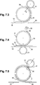
- roller 6 is raised into contact with the accessible part of the mat, and the mat and its heated sheet is in contact with the pipe, as shown on Figure 7.2 .
- out feed table 26 is placed in the retracted position. Translation of the out feed table 26 is obtained with an out feed table motor 33 cooperating with an out feed table screw 34 engaged with the out feed table 26.
- the out feed table 26 is even more driven away along direction F, to manage enough room for the roller 6.
- the process according to the invention doesn't need to place the sheet under tension, only to press it with an appropriate pressure in order for it to adhere.
- the roller is pressed and rolled around the pipe circumference in at first direction C.
- the temperature selection for the sheet is chosen to optimize adhesion with the only constraint being that the mat can withstands the sheet temperature during its application.
- the roller is at its first maximum position in the first rotating direction C, up to a point for example that is almost 170° over the initial point where the roller started to press the sheet onto the pipe. This position is 10° from the apex location 28 of the pipe.
- an overlap heater 29 can be used to maintain the heat of the first overlapping end 30 of the sheet 20 already applied onto the pipe.
- feed table 18 is moved back in order to allow the passage of the roller 6 to press the mat and the heated sheet onto the pipe.
- a feed table motor 27engaging a feed table screw 32 allows translation of the feed table 18.
- the roller 6 goes up to the apex 28, and up to the previous final location in order to bring the second overlapping end 31 of the sheet to overlap the first overlapping end 30.
- the overlap heater 29 provided sufficient heat to ensure both overlapping ends join.
- Overlapping ends 30 and 31 are preferably chamfered in order to limit the overlap thickness.
- roller 6 Through out the rotation of the roller around the pipe, he same pressure is applied to the mat, in order to allow uniform adhesion of the sheet to the pipe, accomplished using the counterweight system.
- the roller 6 is performing a two part turn in respective opposite direction. None the less, if found necessary it is possible to vary the application pressure of roller 6 against the mat and pipe P as a function of the roller position.
- roller When the roller ends the rotation, it rolls back in the first rolling direction C, and allows the mat to separate from the sheet and fall back on the feed table 18.
- the mat 19 allows heat insulation to keep the sheet at a desired temperature.
- the mat helps conformance to the field joint profile due to the specific profile of the mat with longitudinal beads 32.
- the mat 19 is in a material that is not sticking to the sheet, even at the hottest temperature the sheet is brought to.
- the mat 19 is made of an open cell silicon foam layer covered by a silicone rubber film, such film may comprise PTFE.
- the foam layer is larger than the profiled film.
Landscapes
- Engineering & Computer Science (AREA)
- Manufacturing & Machinery (AREA)
- General Engineering & Computer Science (AREA)
- Physics & Mathematics (AREA)
- Thermal Sciences (AREA)
- Mechanical Engineering (AREA)
- Lining Or Joining Of Plastics Or The Like (AREA)
Priority Applications (6)
| Application Number | Priority Date | Filing Date | Title |
|---|---|---|---|
| EP16155584.2A EP3205477A1 (fr) | 2016-02-12 | 2016-02-12 | Machine et procédé d'installation d'une feuille de revêtement sur des sections d'extrémité soudées d'un pipeline |
| GB1812971.8A GB2564273B (en) | 2016-02-12 | 2017-02-09 | Machine and method for installing a coating sheet over welded end sections of pipeline |
| PCT/EP2017/052817 WO2017137474A1 (fr) | 2016-02-12 | 2017-02-09 | Machine et procédé pour l'installation d'une feuille de revêtement sur des sections d'extrémité soudées d'un pipeline |
| CA3013831A CA3013831C (fr) | 2016-02-12 | 2017-02-09 | Machine et procede pour l'installation d'une feuille de revetement sur des sections d'extremite soudees d'un pipeline |
| US16/072,402 US10773453B2 (en) | 2016-02-12 | 2017-02-09 | Machine and method for installing a coating sheet over welded end sections of pipeline |
| NO20180969A NO20180969A1 (en) | 2016-02-12 | 2018-07-11 | Machine and method for installing a coating sheet over welded end sections of pipeline |
Applications Claiming Priority (1)
| Application Number | Priority Date | Filing Date | Title |
|---|---|---|---|
| EP16155584.2A EP3205477A1 (fr) | 2016-02-12 | 2016-02-12 | Machine et procédé d'installation d'une feuille de revêtement sur des sections d'extrémité soudées d'un pipeline |
Publications (1)
| Publication Number | Publication Date |
|---|---|
| EP3205477A1 true EP3205477A1 (fr) | 2017-08-16 |
Family
ID=55527241
Family Applications (1)
| Application Number | Title | Priority Date | Filing Date |
|---|---|---|---|
| EP16155584.2A Withdrawn EP3205477A1 (fr) | 2016-02-12 | 2016-02-12 | Machine et procédé d'installation d'une feuille de revêtement sur des sections d'extrémité soudées d'un pipeline |
Country Status (6)
| Country | Link |
|---|---|
| US (1) | US10773453B2 (fr) |
| EP (1) | EP3205477A1 (fr) |
| CA (1) | CA3013831C (fr) |
| GB (1) | GB2564273B (fr) |
| NO (1) | NO20180969A1 (fr) |
| WO (1) | WO2017137474A1 (fr) |
Cited By (1)
| Publication number | Priority date | Publication date | Assignee | Title |
|---|---|---|---|---|
| CN114920095A (zh) * | 2022-02-08 | 2022-08-19 | 河南新开源石化管道有限公司 | 一种曲率运动半径可调的支撑拖车系统 |
Families Citing this family (4)
| Publication number | Priority date | Publication date | Assignee | Title |
|---|---|---|---|---|
| RU197182U1 (ru) * | 2019-11-19 | 2020-04-08 | Акционерное общество "Делан" | Устройство для намотки изолирующей ленты на наружную поверхность магистрального трубопровода |
| CN113606398B (zh) * | 2021-08-10 | 2022-11-18 | 吉林建筑大学 | 一种桥梁施工用排水管道连接装置 |
| CN115091737B (zh) * | 2022-05-16 | 2023-09-19 | 安徽杰蓝特新材料有限公司 | 一种pe排水管热熔成型管头的成型工艺 |
| IT202300006267A1 (it) * | 2023-03-31 | 2024-10-01 | Gamma Mecc S P A | Apparato per il rivestimento di coppelle di coibentazione. |
Citations (5)
| Publication number | Priority date | Publication date | Assignee | Title |
|---|---|---|---|---|
| US6440245B1 (en) | 1998-11-25 | 2002-08-27 | Socotherm S.R.L. | Method for anticorrosive protection in situ of welding joints and/or of damaged coating areas of metal pipes |
| US7243697B2 (en) | 2000-08-03 | 2007-07-17 | Pipeline Indusction Heat Ltd. | Apparatus and method for coating pipes |
| WO2008107759A1 (fr) * | 2007-03-02 | 2008-09-12 | Saipem S.P.A. | Procédé et appareil de formation d'un revêtement protecteur autour d'un bitume fluidifié entre des conduites faisant partie d'un pipeline sous-marin, et bâtiment de pose de conduites sous-marines comprenant cet appareil |
| US20110259509A1 (en) * | 2010-04-27 | 2011-10-27 | Pirie Strewn S | Pipe Joint Coating |
| US20110297316A1 (en) * | 2010-06-04 | 2011-12-08 | Shawcor Ltd. | Low temperature method and system for forming field joints on undersea pipelines |
Family Cites Families (5)
| Publication number | Priority date | Publication date | Assignee | Title |
|---|---|---|---|---|
| US2696865A (en) * | 1952-01-28 | 1954-12-14 | Main Products Corp | Method of and apparatus for fabricating conveyer belting |
| US3656513A (en) | 1966-10-31 | 1972-04-18 | Continental Can Co | Method of manufacturing container bodies from composite strip material; container body blanks and container bodies |
| US4459251A (en) | 1982-04-29 | 1984-07-10 | Joint Systems, Inc. | Method and apparatus for controlled application of a coating material to a pipe joint |
| NL9400933A (nl) | 1994-06-08 | 1996-01-02 | Allseas Eng Bv | Werkwijze en inrichting voor het leggen van een pijpleiding. |
| ITMI20062402A1 (it) * | 2006-12-14 | 2008-06-15 | Saipem Spa | Metodo e apparecchiatura di giunzione di spezzoni di tubo per realizzare tubazioni sottomarine e natante di posa di tubazioni sottomarine comprendente tale apparecchiatura |
-
2016
- 2016-02-12 EP EP16155584.2A patent/EP3205477A1/fr not_active Withdrawn
-
2017
- 2017-02-09 US US16/072,402 patent/US10773453B2/en active Active
- 2017-02-09 CA CA3013831A patent/CA3013831C/fr active Active
- 2017-02-09 WO PCT/EP2017/052817 patent/WO2017137474A1/fr not_active Ceased
- 2017-02-09 GB GB1812971.8A patent/GB2564273B/en active Active
-
2018
- 2018-07-11 NO NO20180969A patent/NO20180969A1/en unknown
Patent Citations (6)
| Publication number | Priority date | Publication date | Assignee | Title |
|---|---|---|---|---|
| US6440245B1 (en) | 1998-11-25 | 2002-08-27 | Socotherm S.R.L. | Method for anticorrosive protection in situ of welding joints and/or of damaged coating areas of metal pipes |
| US7243697B2 (en) | 2000-08-03 | 2007-07-17 | Pipeline Indusction Heat Ltd. | Apparatus and method for coating pipes |
| WO2008107759A1 (fr) * | 2007-03-02 | 2008-09-12 | Saipem S.P.A. | Procédé et appareil de formation d'un revêtement protecteur autour d'un bitume fluidifié entre des conduites faisant partie d'un pipeline sous-marin, et bâtiment de pose de conduites sous-marines comprenant cet appareil |
| US20110259509A1 (en) * | 2010-04-27 | 2011-10-27 | Pirie Strewn S | Pipe Joint Coating |
| US20140076483A1 (en) | 2010-04-27 | 2014-03-20 | Subsea Services International, Inc. | Pipe joint coating |
| US20110297316A1 (en) * | 2010-06-04 | 2011-12-08 | Shawcor Ltd. | Low temperature method and system for forming field joints on undersea pipelines |
Cited By (1)
| Publication number | Priority date | Publication date | Assignee | Title |
|---|---|---|---|---|
| CN114920095A (zh) * | 2022-02-08 | 2022-08-19 | 河南新开源石化管道有限公司 | 一种曲率运动半径可调的支撑拖车系统 |
Also Published As
| Publication number | Publication date |
|---|---|
| US10773453B2 (en) | 2020-09-15 |
| CA3013831C (fr) | 2024-05-28 |
| GB2564273B (en) | 2021-09-08 |
| NO20180969A1 (en) | 2018-07-11 |
| US20190030786A1 (en) | 2019-01-31 |
| GB201812971D0 (en) | 2018-09-26 |
| CA3013831A1 (fr) | 2017-08-17 |
| WO2017137474A1 (fr) | 2017-08-17 |
| GB2564273A (en) | 2019-01-09 |
Similar Documents
| Publication | Publication Date | Title |
|---|---|---|
| CA3013831C (fr) | Machine et procede pour l'installation d'une feuille de revetement sur des sections d'extremite soudees d'un pipeline | |
| EP2477796B1 (fr) | Procédé et appareil pour le revêtement de tuyaux et de sections de tuyaux | |
| US9441768B2 (en) | Pipe-joining apparatus for producing underwater pipelines | |
| US9956583B2 (en) | Method and device for applying protective sheeting of polymer material to a pipeline | |
| JP5118647B2 (ja) | らせん形に巻かれた構造体を形成するための装置および方法 | |
| US20140076483A1 (en) | Pipe joint coating | |
| US20090065124A1 (en) | Method for the anticorrosion coating and the thermally insulating coating of tubular bodies and conduits for the transport of fluid and apparatus for implementing such method | |
| US7824595B2 (en) | Method and system for cast molding a fluid conduit | |
| CN100354107C (zh) | 金属增强塑料螺旋波纹管的制造装置 | |
| EP2903799B1 (fr) | Procédé, dispositif et poste de travail pour l'application d'un revêtement protecteur en feuille de matériau polymère sur une canalisation et programme informatique pour la mise en oeuvre de ce procédé | |
| CN107405673B (zh) | 在制造多层重型管期间施加包覆层的方法和敷层装置 | |
| IT9021252A1 (it) | Procedimento ed apparecchiatura per rivestire la superficie interna di recipienti | |
| CN112197099B (zh) | 一种防水卷材压紧设备 | |
| JPH0419121A (ja) | 積層スパイラル管の製造方法 | |
| KR102277153B1 (ko) | 엘에이에스 코팅 시트 | |
| RU231962U1 (ru) | Устройство нанесения изолирующего покрытия на основе полимерных лент с клеящимся слоем на неразъемные соединения полиэтилен-сталь | |
| JP2915189B2 (ja) | 積層スパイラル管の製造方法および装置 | |
| JPH01130934A (ja) | 溶接ビードのある防食被覆鋼管の製造装置 | |
| JPH0266217A (ja) | エンボス模様付重防食鋼管杭とその製造方法及び製造装置 |
Legal Events
| Date | Code | Title | Description |
|---|---|---|---|
| PUAI | Public reference made under article 153(3) epc to a published international application that has entered the european phase |
Free format text: ORIGINAL CODE: 0009012 |
|
| AK | Designated contracting states |
Kind code of ref document: A1 Designated state(s): AL AT BE BG CH CY CZ DE DK EE ES FI FR GB GR HR HU IE IS IT LI LT LU LV MC MK MT NL NO PL PT RO RS SE SI SK SM TR |
|
| AX | Request for extension of the european patent |
Extension state: BA ME |
|
| 17P | Request for examination filed |
Effective date: 20171215 |
|
| RBV | Designated contracting states (corrected) |
Designated state(s): AL AT BE BG CH CY CZ DE DK EE ES FI FR GB GR HR HU IE IS IT LI LT LU LV MC MK MT NL NO PL PT RO RS SE SI SK SM TR |
|
| STAA | Information on the status of an ep patent application or granted ep patent |
Free format text: STATUS: THE APPLICATION HAS BEEN WITHDRAWN |
|
| 18W | Application withdrawn |
Effective date: 20180216 |