EP3205571A1 - Durch menschenkraft angetriebenes boot und durch menschenkraft angetriebene antriebsvorrichtung dafür - Google Patents
Durch menschenkraft angetriebenes boot und durch menschenkraft angetriebene antriebsvorrichtung dafür Download PDFInfo
- Publication number
- EP3205571A1 EP3205571A1 EP15849538.2A EP15849538A EP3205571A1 EP 3205571 A1 EP3205571 A1 EP 3205571A1 EP 15849538 A EP15849538 A EP 15849538A EP 3205571 A1 EP3205571 A1 EP 3205571A1
- Authority
- EP
- European Patent Office
- Prior art keywords
- foil
- boat body
- coupled
- propulsion apparatus
- hinge
- Prior art date
- Legal status (The legal status is an assumption and is not a legal conclusion. Google has not performed a legal analysis and makes no representation as to the accuracy of the status listed.)
- Withdrawn
Links
- 239000011888 foil Substances 0.000 claims abstract description 139
- 230000033001 locomotion Effects 0.000 claims abstract description 70
- 230000008878 coupling Effects 0.000 claims description 66
- 238000010168 coupling process Methods 0.000 claims description 66
- 238000005859 coupling reaction Methods 0.000 claims description 66
- XLYOFNOQVPJJNP-UHFFFAOYSA-N water Substances O XLYOFNOQVPJJNP-UHFFFAOYSA-N 0.000 claims description 31
- 230000010355 oscillation Effects 0.000 claims description 9
- 230000007246 mechanism Effects 0.000 abstract description 20
- 230000008859 change Effects 0.000 abstract description 4
- 241000251468 Actinopterygii Species 0.000 abstract description 3
- 230000000694 effects Effects 0.000 description 9
- 238000004519 manufacturing process Methods 0.000 description 5
- 230000008901 benefit Effects 0.000 description 3
- 230000005540 biological transmission Effects 0.000 description 3
- 239000000470 constituent Substances 0.000 description 3
- 239000000243 solution Substances 0.000 description 3
- 230000007423 decrease Effects 0.000 description 2
- 238000013461 design Methods 0.000 description 2
- 238000005516 engineering process Methods 0.000 description 2
- 230000006872 improvement Effects 0.000 description 2
- 238000001746 injection moulding Methods 0.000 description 2
- 238000011056 performance test Methods 0.000 description 2
- 230000009182 swimming Effects 0.000 description 2
- 238000013459 approach Methods 0.000 description 1
- 230000003631 expected effect Effects 0.000 description 1
- 238000009434 installation Methods 0.000 description 1
- 238000000034 method Methods 0.000 description 1
- 230000004048 modification Effects 0.000 description 1
- 238000012986 modification Methods 0.000 description 1
- 238000011160 research Methods 0.000 description 1
- 230000007480 spreading Effects 0.000 description 1
- 230000003068 static effect Effects 0.000 description 1
Images








Classifications
-
- B—PERFORMING OPERATIONS; TRANSPORTING
- B63—SHIPS OR OTHER WATERBORNE VESSELS; RELATED EQUIPMENT
- B63H—MARINE PROPULSION OR STEERING
- B63H1/00—Propulsive elements directly acting on water
- B63H1/30—Propulsive elements directly acting on water of non-rotary type
- B63H1/36—Propulsive elements directly acting on water of non-rotary type swinging sideways, e.g. fishtail type
-
- B—PERFORMING OPERATIONS; TRANSPORTING
- B63—SHIPS OR OTHER WATERBORNE VESSELS; RELATED EQUIPMENT
- B63B—SHIPS OR OTHER WATERBORNE VESSELS; EQUIPMENT FOR SHIPPING
- B63B34/00—Vessels specially adapted for water sports or leisure; Body-supporting devices specially adapted for water sports or leisure
- B63B34/50—Body-supporting buoyant devices, e.g. bathing boats or water cycles
- B63B34/565—Accessories, e.g. sticks for water walking
-
- B—PERFORMING OPERATIONS; TRANSPORTING
- B63—SHIPS OR OTHER WATERBORNE VESSELS; RELATED EQUIPMENT
- B63H—MARINE PROPULSION OR STEERING
- B63H16/00—Marine propulsion by muscle power
- B63H16/04—Oars; Sculls; Paddles; Poles
-
- B—PERFORMING OPERATIONS; TRANSPORTING
- B63—SHIPS OR OTHER WATERBORNE VESSELS; RELATED EQUIPMENT
- B63H—MARINE PROPULSION OR STEERING
- B63H16/00—Marine propulsion by muscle power
- B63H16/08—Other apparatus for converting muscle power into propulsive effort
Definitions
- the present invention relates to a technical field of a boat moving by rowing oars that are taken out from left and right sides of the boat body.
- the boat is mostly compact and uses a non-motorized propulsion apparatus, i.e., human-powered propulsion apparatus as a propulsion apparatus thereof.
- a rider may row oars through a forward and backward movement of rider's arms.
- the human-powered boat uses a human-powered propulsion apparatus having a mechanism that converts a forward and backward movement of a rider's arm into a left and right motion of a foil submerged under the water surface so that the boat moves while the rider faces the front that is an advancing direction of the boat.
- the present invention is based on technical knowledge about 'forward-facing rowing' and 'oscillating foil' so as to safely secure a front view and improve energy efficiency of propulsion when a boat is propelled by using human power.
- the most common example of the forward-facing rowing may be found in narrow beam boats having a sharp boat body such as a kayak or a canoe.
- a pivot may be positioned at a middle portion of each oar.
- the rider may generate propulsion force through a motion that pulls a handle of the oar backward than a motion that pushes the handle of the oar forward.
- the pulling motion may be converted in direction by the pivot, and thus, the boat may be accelerated in a direction opposite to the rider's eyes (backward-facing rowing).
- the simplest solution of the ideas may be an "L-shaped oar", in which a middle portion of an oar's loom is bent.
- the oar When the oar has a shape in which the oar extends from the handle in a width direction of the boat body to meet a side of the boat body and then extends backward in a longitudinal direction of the boat body so that the extending end is coupled to a plate-shaped foil, the forward and backward movement of the rider's arm may be converted into a left and right oscillating motion of the foil to generate propulsion force as if a fish moves a tail fin thereof.
- the oscillating foil may be chosen as best technology in the above-described means that is capable of "generating the propulsion force like a fish" (see Robotic Design for SHOAL - swimming mechanism [on-line], SHOAL Project Consortium, 2012 .)
- a first pivot 11 is disposed on a front end of an oscillating crank 32 having a predetermined length
- a plate-shaped foil 12 is coupled to a rear end of the oscillating crank 32 to allow the oscillating crank 32 to oscillate about the first pivot 11.
- the foil 12 pushes water backward to generate propulsion force F.
- a second pivot 13 is additionally disposed on a front portion of the foil 12 to allow the foil 12 to relatively rotate with respect to the oscillating crank 32, thereby more improving propulsion efficiency.
- the foil 12 rotates about the second pivot 13 in a clockwise direction while largely moving along a rear end of the oscillating crank 32 and then is stopped at a limited angle ⁇ . Thereafter, the foil 12 obliquely pushes water until the oscillating crank 32 reaches a limited angle ⁇ .
- the foil 12 rotates in a counterclockwise direction and stops at a limited angle. Then, the foil 12 pushes water until the oscillating crank 32 reaches the limited angle.
- the foil 12 primarily largely oscillates about the first pivot 11, and simultaneously, secondarily flaps in small about the second pivot 13 to generate the propulsion force F.
- first pivot 11 and the second pivot 13 provide rotation axes that are perpendicular to the water surface to prevent the boat body from pitching due to the oscillation of the foil 12.
- propulsion efficiency can be increased by making the end portion of the foil 12 flexible. (see H. Yamaguchi et al., "Oscillating Foils for Marine Propulsion", The 4th International Society of Offshore and Polar Engineering Conference, vol. 3, 1994, pp. 539-544 .)
- Jack Parker introduced the most simplified mechanism that is imaginable in corresponding technical fields by coupling the foil directly to the first pivot through US Patent Registration No. 7,396,267 (2008.07.08 ).
- US Patent Registration No. 8,419,487 (2013.04.16 ) filed by the same inventor discloses a feature in which the first pivot is moved from the inside to the outside of the boat body.
- An objective of the present invention is to provide a propulsion apparatus having the most simplified structure while maintaining propulsion efficiency of oscillating foil.
- a foil is directly coupled to the first pivot in a state which the oscillating crank is omitted in the propulsion apparatus. Since the essential components for securing effectiveness of oscillating foil mechanism is not prepared, it may be difficult to expect higher propulsion efficiency.
- the foil can rotate at an angle of 180 degrees to generate reverse propulsion force through the same arm movement as the former arm movement (this function enables the rider to perform the forward-facing rowing and the backward-facing rowing). For this, the foil is positioned under a keel of the boat body. If an oscillating crank is added to a front portion of the foil positioned in the deep water, big resistance may occur when rowing.
- the present invention proposes a new solution that indirectly secures some advantages of the prior arts and resolutely abandons some preferable functions of them by totally redesigning the geometry and mechanism of the propulsion apparatus in which the oscillating foil mechanism is applied to the L-shaped oar.
- a human-powered boat which is capable of being propelled by rider's power and constituted by following units including a boat body having a predetermined length and width, at least one mounting means provided at a position that is away by a predetermined distance from a longitudinal axis of the boat body to at least one outside of left and right sides, and at least one propulsion apparatus coupled to the mounting means to operate by a rider's arm, wherein the mounting means provides a first rotation axis in a vertical direction.
- Each of the propulsion apparatuses includes a rotational post fixed in position by the mounting means to rotate about the first rotation axis, a handle crank having a predetermined length and placed in a width direction of the boat body so that an outer end thereof is coupled to an upper portion of the rotational post, an oscillating crank having a predetermined length and placed in a longitudinal direction of the boat body so that a front end thereof is coupled to the rotational post, and a rear end thereof has a height less than that of the outer end of the handle crank, and a plate-shaped foil having a predetermined length and height and coupled to the rear end of the oscillating crank in a longitudinal direction of the boat body.
- the foil may oscillate in a left and right direction about the first rotation axis to generate propulsion force.
- the human-powered boat according to the present invention includes following three limitations.
- the oscillating crank may be spread at an angle of 5 degrees or more in its top plan view to the outside of the boat body to increase the motion range of the foil.
- a flapping hinge having a rotation axis in the vertical direction may be coupled to the rear end of the oscillating crank, and the foil may be coupled to the flapping hinge in a longitudinal direction of the boat body, wherein since the foil horizontally rotates at a predetermined angle about the rotation axis provided by the flapping hinge, the foil may have a specific pitch in generating propulsion force.
- the foil when a side surface of the foil is divided into two front and rear portions by a virtual vertical center line, the rear portion may be more flexible than the front portion.
- the L-shaped propulsion apparatus may be basically used to allow the rider to row in the moving direction of the boat (the rider rows facing forward), thereby giving the psychological stability to the rider.
- the unnecessary additional ideas may be eliminated to provide the propulsion apparatus having the maximally simplified structure while maintaining the high-efficient propulsion property of the oscillating foil mechanism. This may provide the effects of the easy handling and reduced manufacturing costs.
- the motion range for generating the propulsion force at a side of the boat body may be sufficiently secured without using an outrigger to reduce the manufacturing costs and the overall width of the human-powered boat, thereby allowing the boat to be used in the crowded aquatic environments such as the public swimming pool.
- the rider may operate the propulsion apparatus through his/her arm movement freely without being aware of whether the propulsion apparatus is tilted or not, and also, the propulsion apparatus may be easily detached from or mounted on the boat body.
- a means for protecting the propulsion apparatus when colliding with the underwater obstacle may be prepared.
- the foil of the propulsion apparatus has the structure having a vertical rotation axis by itself, the injection molding may be easy, and the manufacturing costs may be reduced.
- the present invention relates to a propulsion apparatus to which an oscillating foil mechanism is applied to an 'L-shaped oar' and a boat that obtains propulsion force by using the same.
- the L-shaped oar means an oar having a 'loom that is bent in an L shape' in the whole outer appearance in a top plan view. This L-shaped oar may convert rider's forward and backward arm movement that is inputted to one end of the oar into a left and right motion of the other end when setting the boat's sailing direction forward.
- FIG. 2A is a schematic top plan view illustrating a human-powered propulsion apparatus and a geometry and mechanism of a human-powered boat using the same according to the present invention.
- a human-powered boat 100 has a structure in which two L-shaped propulsion apparatuses 35 are mounted bilaterally symmetric to each other with respect to a longitudinal axis 99 of a boat body 79 having a predetermined length and width and moving forward (M).
- a human-powered boat 100 may be a boat in a dictionary definition that is a small ship designed to be able to float while moving on water as well as a board concept including an inflatable float having various shapes in which a person rides thereon on water.
- the boat body 79 constituting the human-powered boat 100 of the present invention includes an inflatable float on at least one side of both sides thereof or the boat body is an inflatable float in itself but is not limited thereto.
- a first pivot 11 is positioned away by a predetermined distance outward from a longitudinal axis 99 of the boat body 79, and the propulsion apparatus 35 oscillates about the first pivot 11.
- a potion at which a handle crank 31 and an oscillating crank 32, which serve as an oar's loom in the propulsion apparatus 35, meet approximately perpendicular to each other and then coupled to each other is fixed to the boat body 79 by the first pivot 11.
- the handle crank 31 has a predetermined length and is placed in a width direction of the boat body 79 so that an outer end 33 thereof is coupled to the first pivot 11
- the oscillating crank 32 has a predetermined length and is placed in a longitudinal direction of the boat body 79 so that a front end thereof is coupled to the first pivot 11.
- the handle crank 31 and the oscillating crank 32 are coupled to each other at an angle that is approximately perpendicular to each other, but the angle may be adjusted according to a position of the rider or a structure of the boat body 79.
- a plate-shaped foil 12 having a length and height is coupled to a rear end 34 of the oscillating crank 32 in a longitudinal direction of the boat body 79.
- the foil 12 may oscillate in a left and right direction about the first pivot 11 to generate propulsion force. This operation may correspond to forward-facing rowing in which the rider faces an advancing direction of the boat body 79 and moves the boat.
- the propulsion apparatus 35 is illustrated in a state in which the oscillation is stopped at an angle at which propulsion resistance with respect to a flow of the water in a longitudinal direction of the boat body 79 is smallest and this state may be defined as an idle state in the present invention.
- a second pivot 13 is added to a portion at which the oscillating crank 32 and the foil are coupled to each other.
- the second pivot 13 may allow the propulsion apparatus 35 to have a specific pitch in generating the propulsion force, like a propeller, and the foil 12 may complexly oscillate about the first pivot 11 and the second pivot 13.
- an area on which the foil 12 is swept on a virtual plane that is parallel to the water surface and cuts a center of the foil 12 may be defined as a maximum motion range 21.
- the area is expressed on portions of the propulsion apparatus 35, which are symmetrically opposed to each other, due to spatial restraint.
- FIG. 2B is a schematic front view of the human-powered boat 100 illustrated in FIG. 2A .
- FIG. 2B illustrates a left side of the boat body 79. Since the outer end 33 of the handle crank 31 is positioned in a higher portion of the boat body 79, and the rear end 34 of the oscillating crank 32 is positioned in a lower portion of the boat body 79, it is confirmed that a height difference HI is clearly generated between the outer end 33 and the rear end 34. Further, the rear end 34 of the oscillating crank 32 is positioned higher than the lowest portion of the boat body 79.
- a reason in which a distance ⁇ from a first rotation axis 55 provided by the first pivot 11 to a second rotation axis 66 provided by the second pivot 13 is greater than a straight-line distance L1 from the first rotation axis 55 to the rear end 34 of the oscillating crank 32 in a longitudinal direction of the boat body 79 is for representing the technical knowledge in which the propulsion efficiency of the oscillating foil is improved when the second pivot 13 (or the second rotation axis 66) is positioned backward from a front portion of the foil 12 with somewhat space.
- the foil 12 has a height greater than a length thereof to form a shape that is elongated downward on the whole. This shape may improve the propulsion efficiency by quickly performing a flapping motion of the foil 12 together with the second rotation axis 66 moved backward.
- the above-described human-powered boat and human-powered propulsion apparatus may have three functional limitations in operation thereof.
- the propulsion apparatus 36 having an improved structure in which the oscillating crank 32 is spread outward to increase the motion range 21 of the foil 12 is mounted.
- This improvement may provide an economical effect, in which the motion range 21 is expanded, by locating the foil 12 of the propulsion apparatus farther away outward from the longitudinal axis 99 of the boat body 79, without moving the fixed position of the first pivot 11 outward by adding an outrigger on the boat body 79.
- a ratio of a straight-line distance W1 in a width direction of the boat body 79 to a straight-line distance L2 in a longitudinal direction of the boat body 79 from the first pivot 11 to the end 34 of the oscillating crank has an arc tangent of 5 degrees or more.
- FIG. 2D is a photograph of a state in which a working demonstrator of the human-powered boat is prepared to give a demonstration according to a first embodiment of the present invention in which various functions are added and embodied while maintaining the geometry and mechanism of the human-powered boat 101 in the top plan view illustrated in FIG. 2C .
- the human-powered boat may move at a speed that is greater than a walking speed despite the rider is a child having weak physical strength and the boat causes large propulsion resistance. It is also confirmed that previous education or practice is unnecessary when the propulsion apparatus 36 is initially used, and a reverse propulsion function is unnecessary because the boat is easily changed in direction. This may be impossible or very difficult in case where a child rows a general oar.
- the human-powered boat and the human-powered propulsion apparatus according to the present invention may take the above-described embodied functional limitations as technical features of the present invention.
- the propulsion force of the foil 12 may be generated in the uniform direction to improve the propulsion efficiency.
- the rider may move freely without having a concern of the mistake thereof.
- the maximum motion range 21 of the foil 12 does not cross the longitudinal axis 99 of the boat body 79.
- the function of each of the propulsion apparatuses 35 and 36 as a static rudder may be limited.
- the propulsion apparatus according to the present invention since the propulsion apparatus according to the present invention generates the propulsion force on the side of the boat body 79, the direction change may be enabled by causing a difference in left and right propulsion forces of the boat body 79. As a result, a dynamic rudder function is maintained as ever.
- the portion overlapped by each other may be less than 30% of the total area of the maximum motion range 21.
- the range in which the propulsion force is generated may be limited in size.
- a smaller overlapping portion is preferable, but the size percentage of overlapped portion is set under consideration of a change in draft according to loaded weight.
- each of the propulsion apparatuses is limited in size and capacity. If the propulsion apparatus mounted on the side of the boat body 79 operates to cross the longitudinal axis 99 of the boat body 79, the oscillating crank 32 may be elongated, or a power transmission device may be added thereby increasing a size of the propulsion apparatus. Therefore, this functional limitation may be necessary to simplify the propulsion apparatus. Since it has a clear limitation to improve the propulsion efficiency by increasing the maximum motion range of the foil 12 under the condition in which the limited human power is used as input power, this limitation may be preferable in consideration of the 'scale efficiency'.
- the propulsion apparatus widely operates under the area of the boat body 79 that is submerged in the water, the portion of the oscillating crank 32, which is submerged in the water increases (because the depth of the boat body 79 generally increases in cross-section toward a middle portion thereof) thereby causing unnecessary propulsion resistance.
- this limitation may act as a direct pulse effect in improving of the propulsion efficiency.
- the present invention adopts the three functional limitations to maximize the simplicity of the apparatus while maintaining the propulsion efficiency and obtain the reflective improvement in performance from each of the limitations.
- removing unnecessary ideas may improve the values of products.
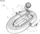
- the human-powered boat according to the first embodiment 101 of the present invention will be described in detail with reference to FIGS. 3A to 3C .
- the human-powered boat 101 has a structure in which two L-shaped propulsion apparatuses 36 and 36' are mounted on an inflatable boat body 179 having a predetermined length and width and moving forward, and bilaterally symmetrical to each other with respect to the longitudinal axis 99 of the boat body 179.
- Each of the propulsion apparatuses 36 and 36' illustrated in FIG. 3B is in an idle state.
- mounting means 37 and 37' may be coupled to positions that are away by a predetermined distance outward from the longitudinal axis 99 to left and right sides of the boat body 179, and the propulsion apparatuses 36 and 36' each of which has an L-shaped oar are respectively coupled to the mounting means 37 and 37'.
- the mounting means 37 and 37' may provide first pivots 11 and 11' to the propulsion apparatuses 36 and 36' coupled thereto, respectively.
- the propulsion apparatuses 36 and 36' may overall oscillate about the first pivots 11 and 11', respectively.
- Oars' looms which determine the whole shapes of the propulsion apparatuses in FIG. 3B , may be formed by coupling handle cranks 31 and 31' to oscillating cranks 32 and 32'. It is seen that the first pivots 11 and 11' are positioned on places at which the handle cranks 31 and 31' and the oscillating cranks 32 and 32' meet to be coupled to each other.
- Each of the handle cranks 31 and 31' has a predetermined length and is placed in a width direction of the boat body 179 so that an outer end thereof is coupled to each of the first pivots 11 and 11'.
- each of the oscillating cranks 32 and 32' has a predetermined length and is placed in a longitudinal direction of the boat body 179 so that a front end thereof is coupled to each of the first pivots 11 and 11'.
- each of the handle cranks 31 and 31' and each of the oscillating cranks 32 and 32' are coupled to each other at an angle that is approximately perpendicular to each other.
- the angle may be adjusted according to a position of the rider or a structure of the boat body 179.
- each of plate-shaped foils 12 and 12' is coupled to a rear end of each of the oscillating cranks 32 and 32' in a longitudinal direction of the boat body 179.
- the foils 12 and 12' may oscillate in a left and right direction about each of the first pivots 11 and 11' to generate propulsion force. This operation may correspond to forward-facing rowing in which the rider faces an advancing direction of the boat body 179 and moves the boat.
- FIG. 3C illustrates a right side view of the human-powered boat according to the first embodiment of the present invention.
- the handle crank 31 is positioned above the mounting means 37
- the oscillating crank 32 is positioned below the mounting means 37.
- the oscillating crank 32 is positioned above the water surface and thus does not contact the water surface during the operation, and the whole of the foil 12 may be submerged under the water surface if possible.
- the human-powered propulsion apparatus may represent a combination of the mounting means and the propulsion apparatus.
- FIGS. 4A to 4C are views of the human-powered propulsion apparatus of FIG. 3A according to the first embodiment of the present invention. Only the propulsion apparatus 36 mounted on the left side of the boat body 179 and operated by a left hand of the rider and the mounting means 37 fixing the propulsion apparatus 36 to the boat body 179 are illustrated.
- the mounting means 37 positioned on the side of the boat body 179 provides a first rotation axis 55 in a vertical direction to the propulsion apparatus 36 paired therewith.
- the propulsion apparatus 36 includes a rotational post 30 fixed in position by the mounting means 37 to rotate about the first rotation axis 55, a handle crank 31 having a predetermined length and placed in a width direction of the boat body 179 so that an outer end thereof is coupled to an upper portion of the rotational post 30, an oscillating crank 32 having a predetermined length and placed in a longitudinal direction of the boat body 179 so that a front end thereof is coupled to the rotational post 30, and a plate-shaped foil 12 having a predetermined length and width and coupled to a rear end of the oscillating crank 32 in a longitudinal direction of the boat body 179.
- the rider grasps the handle crank 31 and alternately move forward and backward, the foil 12 oscillates about the first rotation axis 55 to generate propulsion force.
- a ratio W1/L2 of a straight-line distance W1 from the first pivot 11 to an end of the oscillating crank 32 in a width direction of the boat body 179 to a straight-line distance L2 from the first pivot 11 to an end 34 of the oscillating crank 32 in a longitudinal direction of the boat body 179 may has an arc tangent value of 5 degrees or more. According to the geometry, a sufficient motion range 221 in which the foil 12 oscillates in the left and right directions may be secured although the mounting means 37 is closely coupled to the side of the inflatable boat body 179.
- the motion range of the foil 12 may increase without spreading a rear portion of the oscillating crank to the outside of the boat body 179.
- a rear end 34 of the oscillating crank 32 has a height less by a predetermined height HI than that of an outer end 33 of the handle crank 31. This is done because the height at which the rider easily moves an arm is higher than the water surface.
- the rear end 34 of the oscillating crank 32 may be positioned higher than the lowest portion of the boat body 179. This is intended to reduce the propulsion resistance during the operation by minimizing the portion of the oscillating crank 32, which is submerged under the water surface.
- a flapping hinge 67 having a rotation axis 66 in a vertical direction is coupled to the rear end of the oscillating crank 32, and then, the foil 12 is coupled to the flapping hinge 67 in a longitudinal direction of the boat body 179.
- the foil 12 horizontally rotates at a predetermined angle ⁇ about the rotation axis 66 provided by the flapping hinge 67, the foil 12 has a specific pitch in generating propulsion force, like a propeller.
- the rotation axis 66 provided by the flapping hinge 67 may be the same as the rotation axis provided by the second pivot 13, which is illustrated in FIGS. 1, 2A , 2C , and 4B .
- the foil 12 has a shape that is vertically elongated on the whole, so that the foil 12 has a height greater than a length thereof, Also, it is preferable that a rear portion of the foil 12 is more flexible than a front portion of the foil 12 when a side surface of the foil 12 is divided into two front and rear portions by using a virtual vertical center line 88.
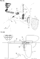
- the human-powered propulsion apparatus according to the first embodiment of the present invention will be more particularly described with reference to exploded views and operations illustrated in FIGS. 5A to 5G .
- a motion hinge 77 having a rotation axis 771 in a longitudinal direction of the boat body 179 is coupled to an upper portion of the rotational post 30, and an outer end of the handle crank 31 is coupled to the motion hinge 77 in a width direction of the boat body 179.
- the handle crank 31 may oscillate at a predetermined angle about the rotation axis provided by the motion hinge 77.
- an upward and downward motion may be added to a forward and backward motion to allow the rider's hand moves along an oval path at if the rider rows a general oar.
- the motion transmitted to the oscillating crank 32 in FIG. 5A may be only the oscillation about the first rotation axis 55.
- the motion hinge 77 may be provided by coupling a first coupling element 774 coupled to the handle crank 31 to a second coupling element 773 coupled to the rotational post 30 by inserting a hinge pin 772 having a rotation axis 771 in a longitudinal direction of the boat body 179.
- the vertical oscillating motion range of the handle crank 31 is limited from a horizontal line to a vertical line. This may be easily realized by forming an L-shaped hooking portion 775 in the second coupling element 773.
- a retracting hinge 78 having a rotation axis 781 in a width direction of the boat body 179 is coupled to the rear portion of the oscillating crank 32, and the foil 12 is coupled to the retracting hinge 78 in a longitudinal direction of the boat body 179.
- the foil 12 when the foil 12 collides with an underwater obstacle 789, the foil 12 may rotate at a predetermined angle about the rotation axis provided by the retracting hinge 78 and be lifted upward to reduce the risk of damage.
- the vertical oscillating motion range of the foil 12 is limited from a vertical line to horizontal line. This may be easily realized by forming an L-shaped hooking portion 783 in a third coupling element.
- two hinges such as the flapping hinge 67 and the retracting hinge 78 may be added when the oscillating crank 32 and the foil 12 of the human-powered propulsion apparatus are coupled to each other.
- a third coupling element 783 is coupled to the rear end of the oscillating crank 32, and then, a fourth coupling element 784 is coupled by using a horizontal hinge pin 782 to constitute the retracting hinge 78.
- a fifth coupling element 674 is coupled to a rear portion of the fourth coupling element 784 by using a vertical hinge pin 672 to constitute the flapping hinge 67.
- the foil 12 is coupled to a rear portion of the fifth coupling element 674 in a longitudinal direction of the boat body 179.
- the fourth coupling element 784 includes at least one or more rings 785 that are spaced away at a predetermined distance from each other along the second rotation axis 66 provided by the vertical hinge pin 672, and the fifth coupling element 674 includes at least one or more rings 675 that are disposed to miss the rings of the fourth coupling element.
- the rings 786 and 675 respectively provided at the elements may be engaged with each other like gears and then strung downward from top to bottom in a line by using the vertical hinge pin 672 and fixed in position.
- two hinge's function may be realized at the same time with small number of components. Also, since it is impossible to disassemble the flapping hinge 67 without withdrawing the hinge pin 782 constituting the retracting hinge 78, the flapping hinge 67 that has to endure vibrations may be improved in durability.
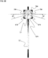
- At least one stopping protrusion 786 is disposed on each of left and right sides of the fourth coupling element 784, and at least one stopping protrusion 676 is disposed on each of left and right sides of the fifth coupling element 674. Since the stopping protrusions 786 and 676 are positioned at the same height when being coupled, if the foil 12 starts to rotate in one direction from the idle state illustrated in FIG. 5E (a rear view) with respect to the oscillating crank 32, the rotation stops when the stopping protrusions 786 and 676 meet together, so that the maximum rotation range of the fin is defined.
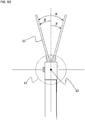
- the oscillation of the foil 12 with respect to the oscillating crank 32 is illustrated in the top plan view of FIG. 5G .
- the second rotation axis 66 provided by the flapping hinge 67 may be the same as the second pivot 13 on the drawing.
- Angles ⁇ and ⁇ ' at which the foil rotates in a left or right direction with respect to the idle state may be different from each other. In this case, it is preferable that the internal angle positioned closer to the boat body 179 is greater than another angle ( ⁇ > ⁇ ').
- the oscillating crank 32 is coupled to a lower portion of the rotational post 30, it is difficult to detach or mount the propulsion apparatus 36 from or to the mounting means 37.
- the boat body 179 is inflatable as described in the human-powered boat according to the first embodiment of the present invention, or a potion of the boat body 179, on which the mounting means is fixed, is provided as an inflatable float
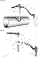
- the mounting means 37 may be divided into at least two components 371 and 372 by using at least one vertical cross-section as illustrated in the perspective view of FIG. 6A , contact surfaces of at least two components constituting the mounting means 37 may be spread to easily detach the propulsion apparatus 36 from the mounting means 37 in a state in which air within the boat body 179 may be discharged to reduce an internal pressure as illustrated in FIG. 6B .
- the vertically divided mounting means 37 may be manufactured through injection molding by using a simple mold and thus reduced in manufacturing costs.
- the boat body is for a one-seater boat and two propulsion apparatuses 36 and 36' positioned bilaterally symmetrical to each other are mounted on the boat body.
- each of the propulsion apparatuses may be asymmetrically disposed on left and right sides one another.
- the symmetrical feature of the propulsion apparatuses may be flexibly applicable.
- the present invention may include a structure in which only one propulsion apparatus is mounted on one side of the boat body 179, and the general oar is rowed at an opposite side.
- FIGS. 7A to 7E are views of a human-powered propulsion apparatus according to a second embodiment of the present invention.
- a human-powered propulsion apparatus 336 according to a second embodiment of the present invention it is confirmed that an oscillating crank 322 is coupled to an upper portion of a rotational post 30, unlike the propulsion apparatus 36 according to the foregoing first embodiment.
- the oscillating crank 322 gradually decreases in height from a portion thereof coupled to the rotational post 30 to a rear of a boat body 179 and then is coupled to a foil 12.
- a shape in which the oscillating crank 322 is inclined backward and downward may provide an effect in which energy loss is less because a portion of the oscillating crank 322, which is submerged under the water, is reduced even though the boat body 179 is deeply submerged under the water surface due to the large loadage.
- the largest advantage of the propulsion apparatus 336 having the geometry is that the propulsion apparatus 336 may be easily lifted and detached from the boat body 179 as illustrated in FIG. 7C .
- the rotational post 30 may be simply inserted into the mounting means 37 to mount the propulsion apparatus 336 on the boat body 179.
- a folding hinge 56 having a rotation axis 561 in a width direction of the boat body 179 is added to the coupled portion between the rotational post 30 and the oscillating crank 322.
- the folding hinge 56 includes a sixth coupling element 562 coupled to the rotational post 30, and a seventh coupling element 563 inserted into the folding hinge 56 to rotate at a fixed angle about the rotation axis 561 in a width direction of the boat body 179 and coupled to a front end of the oscillating crank 322.
- the sixth coupling element 562 and the seventh coupling element 563 do not have to be separated from each other during the operation of the propulsion apparatus 336 and have to provide a function that restricts the oscillating crank 322 so that the oscillating crank 322 stops to rotate downward at a specific angle. Since this is capable of being secured through a simple design change of the folding hinge 56, such as adding of a predetermined locking means operable by a rider's hand and a modification of contact surfaces of the two coupling elements 562 and 563 into uneven surfaces, its detailed description will be omitted in the present invention.
- the propulsion apparatus 336 may be reduced in overall volume because the oscillating crank 322 rotates upward at a predetermined angle about the rotation axis 561 provided by the folding hinge 56 and then is lifted.
- the propulsion apparatus 336 is detached from the boat body 179, and then, a handle crank 31 is folded upward with respect to a motion hinge 77. Then, the oscillating crank 322 is folded upward with respect to the folding hinge 56, and then, a foil 12 is folded upward with respect to a retracting hinge 78 to reduce the overall volume. Therefore, the propulsion apparatus 336 may be easily carried and stored.
- the folding hinge 56 provides the same effect when the folding hinge 56 is applied to the human-powered propulsion apparatus 36 according to the first embodiment.
- the handle cranks 31 and 31' and the oscillating cranks 32, 32,' and 322 of the human-powered propulsion apparatus according to the present invention have to be changed in length according to the boat body 179 or a body size of the rider.
- the boat body 179 increases in width thereby increasing a distance from the rider's position to the mounting means, it is necessary to increase a length of each of the handle cranks 31 and 31'.
- the increase in length of each of the oscillating cranks 32, 32' and 322 may be effective as a method for expanding the motion range of each of the foils 12 and 12'.
- each of the handle cranks 31 and 31' or the oscillating cranks 32, 32' and 322 may have a telescopic tube structure that is adjustable in length. Since this structure is commonly found from an umbrella to a smartphone antenna, the structure will be omitted in the drawings.
- the telescope tube structure may include a stopping means for fixing the telescopic tube such after a length of the telescope tube is adjusted as a screw.
- a constituent for remotely adjusting a length of each of the oscillating cranks 32, 32' and 322 by using a string may be added. Since these constituents are commonly adopted to operate a sail or rudder in the small-sized boat technical fields, their detailed descriptions will be omitted.
- the human-powered boat according to the second embodiment of the present invention may represent a human-powered boat in which the human-powered propulsion apparatus according to the second embodiment is mounted on the boat body 179 of the human-powered boat according to the first embodiment.
- the human-powered boat according to the third embodiment of the present invention may represent a human-powered boat in which the human-powered propulsion apparatus according to the third embodiment is mounted on the boat body 179 of the human-powered boat according to the first embodiment.
- the telescope tube structure of the human-powered propulsion apparatus according to the third embodiment may be applied to the handle crank of the human-powered propulsion apparatus according to the second embodiment
- the folding hinge of the human-powered propulsion apparatus according to the second embodiment may be applied to the human-powered boat according to the first embodiment.
- the structure in which the mounting means of the human-powered boat according to the first embodiment is divided into at least two components may be applied to the human-powered boat according to the second or third embodiment.
- the present invention relates to the non-motorized movable human-powered boat and the human-powered propulsion apparatus thereof.
- the present invention may be applied to the structure in which the rider rows the oar through the forward and backward movement of the rider's arm while facing the advancing direction of the boat.
Landscapes
- Chemical & Material Sciences (AREA)
- Engineering & Computer Science (AREA)
- Combustion & Propulsion (AREA)
- Mechanical Engineering (AREA)
- Ocean & Marine Engineering (AREA)
- Toys (AREA)
- Wind Motors (AREA)
Applications Claiming Priority (2)
| Application Number | Priority Date | Filing Date | Title |
|---|---|---|---|
| KR1020140134083A KR101553781B1 (ko) | 2014-10-06 | 2014-10-06 | 인력추진보트와 그를 위한 인력추진장치 |
| PCT/KR2015/010546 WO2016056816A1 (ko) | 2014-10-06 | 2015-10-06 | 인력추진보트와 그를 위한 인력추진장치 |
Publications (2)
| Publication Number | Publication Date |
|---|---|
| EP3205571A1 true EP3205571A1 (de) | 2017-08-16 |
| EP3205571A4 EP3205571A4 (de) | 2018-05-30 |
Family
ID=54248504
Family Applications (1)
| Application Number | Title | Priority Date | Filing Date |
|---|---|---|---|
| EP15849538.2A Withdrawn EP3205571A4 (de) | 2014-10-06 | 2015-10-06 | Durch menschenkraft angetriebenes boot und durch menschenkraft angetriebene antriebsvorrichtung dafür |
Country Status (5)
| Country | Link |
|---|---|
| US (1) | US9988130B2 (de) |
| EP (1) | EP3205571A4 (de) |
| KR (1) | KR101553781B1 (de) |
| CN (1) | CN107531314A (de) |
| WO (1) | WO2016056816A1 (de) |
Families Citing this family (7)
| Publication number | Priority date | Publication date | Assignee | Title |
|---|---|---|---|---|
| KR101679559B1 (ko) * | 2016-07-24 | 2016-11-25 | (주)다이나필 | 인력으로 추진하는 수상이동수단과 그를 위한 간편하게 접을 수 있는 인력추진장치 |
| US11858599B2 (en) | 2020-01-29 | 2024-01-02 | Matthew Adam Becker | Dual motor propulsion system for watercraft |
| CN111470016B (zh) * | 2020-05-20 | 2025-04-29 | 威海海洋职业学院 | 一种船舶驱动装置 |
| CN113617006B (zh) * | 2021-08-13 | 2022-07-22 | 北京健入家境体育科技有限公司 | 一种可模拟多人同艇赛艇运动的方法 |
| CN113734404A (zh) * | 2021-09-10 | 2021-12-03 | 方松 | 一种游乐园船桨用驱动装置 |
| CN114104236A (zh) * | 2021-11-30 | 2022-03-01 | 中国船舶科学研究中心 | 一种新型仿生振荡翼的组合运动方式 |
| WO2024084418A1 (en) * | 2022-10-21 | 2024-04-25 | Railblaza Limited | Transducer pole system with adjustment features |
Family Cites Families (27)
| Publication number | Priority date | Publication date | Assignee | Title |
|---|---|---|---|---|
| US227491A (en) * | 1880-05-11 | Sculling-propeller for boats | ||
| US2156898A (en) * | 1937-12-13 | 1939-05-02 | Giudice Don C Lo | Propulsion means |
| GB959894A (en) * | 1960-10-05 | 1964-06-03 | Thomas James Gregory | Improvements in or relating to propulsion means for boats |
| US3834343A (en) * | 1972-11-14 | 1974-09-10 | W Hopkins | Articulated sculling oar |
| US3874320A (en) * | 1973-11-16 | 1975-04-01 | Wilburn W Wood | Boat propulsion apparatus |
| US3880107A (en) * | 1974-01-18 | 1975-04-29 | John C Miles | Propulsion device for water craft |
| US4172427A (en) * | 1978-01-12 | 1979-10-30 | Kindred William B | Water propulsion unit including fin having foil and flexible ends |
| US4345903A (en) * | 1980-01-03 | 1982-08-24 | Otto Laser | Fin propulsion boat |
| US4642056A (en) * | 1985-05-28 | 1987-02-10 | Massoud Keivanjah | Recreational water craft |
| US4867719A (en) | 1987-02-03 | 1989-09-19 | Dupont Stephen | Hydrofoil oar with movable outrigger |
| US4867718A (en) | 1987-02-03 | 1989-09-19 | Dupont Stephen | Hydrofoil oar |
| FR2825678B1 (fr) * | 2001-06-07 | 2003-09-12 | Zodiac Int | Dispositif de fixation amovible d'un aviron sur une embarcation |
| KR20030034774A (ko) | 2001-10-24 | 2003-05-09 | 김남길 | 생명 안전 보트 장착용 추진 장치 |
| US6964589B1 (en) | 2005-03-15 | 2005-11-15 | Roger Lin | Sculling boat assembly |
| AU2005201154A1 (en) * | 2005-03-17 | 2006-10-05 | Roger Lin | Small boat rowing mechanism |
| JP5135685B2 (ja) | 2006-01-12 | 2013-02-06 | 達郎 横井 | 揺動式横ヒレ推進人力船 |
| US7396267B1 (en) * | 2006-08-24 | 2008-07-08 | Parker Jack W | Watercraft rowing fin system |
| US7878135B1 (en) * | 2007-05-09 | 2011-02-01 | Nauticraft Corporation | Swing-up rudder for small boat |
| CN201313629Y (zh) * | 2008-11-14 | 2009-09-23 | 陶醉 | 仿生船 |
| US8419487B2 (en) | 2009-08-13 | 2013-04-16 | Jack Parker | Internally mounted watercraft rowing fin system |
| KR20110080696A (ko) | 2010-01-07 | 2011-07-13 | 신병철 | 터널형 자세 안정수단을 갖춘 수상이동장비 |
| KR101659256B1 (ko) | 2010-01-13 | 2016-09-22 | (주)다이나필 | 돔형 자세 안정수단을 갖춘 수상이동장비 |
| CN201971143U (zh) * | 2010-11-11 | 2011-09-14 | 太仓市车中宝休闲用品有限公司 | 划船对橹 |
| KR101328361B1 (ko) | 2012-03-15 | 2013-11-11 | 김명수 | 노를 구비한 튜브형 보트 |
| CN102616362B (zh) * | 2012-04-05 | 2014-12-17 | 太仓市车中宝休闲用品有限公司 | 划船对橹 |
| CN202987487U (zh) * | 2012-12-06 | 2013-06-12 | 浙江海洋学院 | 一种依靠人力驱动的小型水翼艇 |
| CN103101607A (zh) * | 2012-12-10 | 2013-05-15 | 大连九星科技有限公司 | 一种浮球式摇橹船 |
-
2014
- 2014-10-06 KR KR1020140134083A patent/KR101553781B1/ko not_active Expired - Fee Related
-
2015
- 2015-10-06 EP EP15849538.2A patent/EP3205571A4/de not_active Withdrawn
- 2015-10-06 US US15/517,089 patent/US9988130B2/en active Active
- 2015-10-06 WO PCT/KR2015/010546 patent/WO2016056816A1/ko not_active Ceased
- 2015-10-06 CN CN201580066261.6A patent/CN107531314A/zh active Pending
Also Published As
| Publication number | Publication date |
|---|---|
| US9988130B2 (en) | 2018-06-05 |
| WO2016056816A1 (ko) | 2016-04-14 |
| KR101553781B1 (ko) | 2015-09-16 |
| CN107531314A (zh) | 2018-01-02 |
| US20170305517A1 (en) | 2017-10-26 |
| EP3205571A4 (de) | 2018-05-30 |
Similar Documents
| Publication | Publication Date | Title |
|---|---|---|
| EP3205571A1 (de) | Durch menschenkraft angetriebenes boot und durch menschenkraft angetriebene antriebsvorrichtung dafür | |
| Hirata et al. | Study on turning performance of a fish robot | |
| US3677216A (en) | Rowing device | |
| US7232350B1 (en) | Human powered watercraft | |
| US8043134B2 (en) | Human powered watercraft | |
| JPH08502224A (ja) | 半潜水艇 | |
| US7736205B2 (en) | Human powered watercraft | |
| US3377977A (en) | Combination sculling and surfboard | |
| KR101240749B1 (ko) | 인명구조용 제트스키 | |
| GB2101946A (en) | Oar mounting system | |
| US5669793A (en) | Apparatus and method for propelling a water vehicle | |
| US20040043679A1 (en) | Front facing rowing apparatus | |
| US6848958B2 (en) | Manually propelled personal flotation device | |
| JP6898691B2 (ja) | 人力推進ボート | |
| US3903834A (en) | Hand-driven water craft | |
| JP4234533B2 (ja) | 曳航式水中潜水機 | |
| JP2019077234A (ja) | 人力推進ボート | |
| CN221606028U (zh) | 一种应急救援用铝合金底充气艇 | |
| US6736688B1 (en) | Manually propelled personal floatation device | |
| RU211944U1 (ru) | Поплавковое весло | |
| KR101327532B1 (ko) | 추진 핀의 좌우 추진식 수상 자전거 | |
| US3111110A (en) | Boat propulsion | |
| KR100520004B1 (ko) | 노 추진장치 | |
| JPH0717227B2 (ja) | 小型ジエツト推進艇 | |
| JP3048492B2 (ja) | ウォータクラフト |
Legal Events
| Date | Code | Title | Description |
|---|---|---|---|
| STAA | Information on the status of an ep patent application or granted ep patent |
Free format text: STATUS: THE INTERNATIONAL PUBLICATION HAS BEEN MADE |
|
| PUAI | Public reference made under article 153(3) epc to a published international application that has entered the european phase |
Free format text: ORIGINAL CODE: 0009012 |
|
| STAA | Information on the status of an ep patent application or granted ep patent |
Free format text: STATUS: REQUEST FOR EXAMINATION WAS MADE |
|
| 17P | Request for examination filed |
Effective date: 20170505 |
|
| AK | Designated contracting states |
Kind code of ref document: A1 Designated state(s): AL AT BE BG CH CY CZ DE DK EE ES FI FR GB GR HR HU IE IS IT LI LT LU LV MC MK MT NL NO PL PT RO RS SE SI SK SM TR |
|
| AX | Request for extension of the european patent |
Extension state: BA ME |
|
| DAV | Request for validation of the european patent (deleted) | ||
| DAX | Request for extension of the european patent (deleted) | ||
| A4 | Supplementary search report drawn up and despatched |
Effective date: 20180504 |
|
| RIC1 | Information provided on ipc code assigned before grant |
Ipc: B63H 16/04 20060101AFI20180426BHEP Ipc: B63H 16/08 20060101ALI20180426BHEP Ipc: B63H 1/36 20060101ALI20180426BHEP |
|
| STAA | Information on the status of an ep patent application or granted ep patent |
Free format text: STATUS: EXAMINATION IS IN PROGRESS |
|
| 17Q | First examination report despatched |
Effective date: 20181218 |
|
| STAA | Information on the status of an ep patent application or granted ep patent |
Free format text: STATUS: THE APPLICATION IS DEEMED TO BE WITHDRAWN |
|
| 18D | Application deemed to be withdrawn |
Effective date: 20200311 |