EP3205595A1 - Fermeture de bouteille comprenant un joint à lamelles tubulaire - Google Patents
Fermeture de bouteille comprenant un joint à lamelles tubulaire Download PDFInfo
- Publication number
- EP3205595A1 EP3205595A1 EP17156055.0A EP17156055A EP3205595A1 EP 3205595 A1 EP3205595 A1 EP 3205595A1 EP 17156055 A EP17156055 A EP 17156055A EP 3205595 A1 EP3205595 A1 EP 3205595A1
- Authority
- EP
- European Patent Office
- Prior art keywords
- cap
- shaft
- bottle closure
- lamellar seal
- bottle
- Prior art date
- Legal status (The legal status is an assumption and is not a legal conclusion. Google has not performed a legal analysis and makes no representation as to the accuracy of the status listed.)
- Granted
Links
- 238000007789 sealing Methods 0.000 claims abstract description 42
- 235000013361 beverage Nutrition 0.000 claims abstract description 12
- 230000002093 peripheral effect Effects 0.000 claims abstract description 4
- 229920003023 plastic Polymers 0.000 claims description 24
- 239000004033 plastic Substances 0.000 claims description 24
- 239000000463 material Substances 0.000 claims description 23
- -1 polyethylene Polymers 0.000 claims description 19
- 239000004698 Polyethylene Substances 0.000 claims description 16
- 239000004743 Polypropylene Substances 0.000 claims description 11
- DQXBYHZEEUGOBF-UHFFFAOYSA-N but-3-enoic acid;ethene Chemical compound C=C.OC(=O)CC=C DQXBYHZEEUGOBF-UHFFFAOYSA-N 0.000 claims description 11
- 239000005038 ethylene vinyl acetate Substances 0.000 claims description 11
- 229920001200 poly(ethylene-vinyl acetate) Polymers 0.000 claims description 11
- XECAHXYUAAWDEL-UHFFFAOYSA-N acrylonitrile butadiene styrene Chemical compound C=CC=C.C=CC#N.C=CC1=CC=CC=C1 XECAHXYUAAWDEL-UHFFFAOYSA-N 0.000 claims description 10
- 239000004676 acrylonitrile butadiene styrene Substances 0.000 claims description 10
- 229920000122 acrylonitrile butadiene styrene Polymers 0.000 claims description 10
- 229920003229 poly(methyl methacrylate) Polymers 0.000 claims description 10
- 229920000139 polyethylene terephthalate Polymers 0.000 claims description 10
- 239000005020 polyethylene terephthalate Substances 0.000 claims description 10
- 239000004926 polymethyl methacrylate Substances 0.000 claims description 10
- SCUZVMOVTVSBLE-UHFFFAOYSA-N prop-2-enenitrile;styrene Chemical compound C=CC#N.C=CC1=CC=CC=C1 SCUZVMOVTVSBLE-UHFFFAOYSA-N 0.000 claims description 10
- 229920000638 styrene acrylonitrile Polymers 0.000 claims description 10
- 239000004793 Polystyrene Substances 0.000 claims description 9
- 239000004417 polycarbonate Substances 0.000 claims description 9
- 229920000573 polyethylene Polymers 0.000 claims description 9
- 229920000515 polycarbonate Polymers 0.000 claims description 7
- 229920002223 polystyrene Polymers 0.000 claims description 6
- 229920001634 Copolyester Polymers 0.000 claims description 5
- 238000000034 method Methods 0.000 claims description 5
- 229920001155 polypropylene Polymers 0.000 claims description 5
- 238000005507 spraying Methods 0.000 claims description 3
- 235000019993 champagne Nutrition 0.000 abstract description 7
- 235000015096 spirit Nutrition 0.000 abstract description 4
- 235000014101 wine Nutrition 0.000 abstract description 4
- 235000011389 fruit/vegetable juice Nutrition 0.000 abstract description 2
- 238000004519 manufacturing process Methods 0.000 description 10
- 238000001746 injection moulding Methods 0.000 description 7
- 235000013305 food Nutrition 0.000 description 4
- 239000011521 glass Substances 0.000 description 4
- 239000007788 liquid Substances 0.000 description 4
- 230000000007 visual effect Effects 0.000 description 4
- 241001411320 Eriogonum inflatum Species 0.000 description 3
- 241000446313 Lamella Species 0.000 description 3
- 235000014214 soft drink Nutrition 0.000 description 3
- 230000001476 alcoholic effect Effects 0.000 description 2
- 235000014171 carbonated beverage Nutrition 0.000 description 2
- 230000006378 damage Effects 0.000 description 2
- 238000013016 damping Methods 0.000 description 2
- 238000013461 design Methods 0.000 description 2
- 238000003780 insertion Methods 0.000 description 2
- 230000037431 insertion Effects 0.000 description 2
- 229920000642 polymer Polymers 0.000 description 2
- 239000013585 weight reducing agent Substances 0.000 description 2
- 208000027418 Wounds and injury Diseases 0.000 description 1
- 239000000853 adhesive Substances 0.000 description 1
- 238000004026 adhesive bonding Methods 0.000 description 1
- 230000001070 adhesive effect Effects 0.000 description 1
- BVKZGUZCCUSVTD-UHFFFAOYSA-N carbonic acid Chemical compound OC(O)=O BVKZGUZCCUSVTD-UHFFFAOYSA-N 0.000 description 1
- 239000003795 chemical substances by application Substances 0.000 description 1
- 239000000356 contaminant Substances 0.000 description 1
- 239000007799 cork Substances 0.000 description 1
- 238000011161 development Methods 0.000 description 1
- 230000000694 effects Effects 0.000 description 1
- 238000002347 injection Methods 0.000 description 1
- 239000007924 injection Substances 0.000 description 1
- 208000014674 injury Diseases 0.000 description 1
- 229920001684 low density polyethylene Polymers 0.000 description 1
- 239000004702 low-density polyethylene Substances 0.000 description 1
- 230000002906 microbiologic effect Effects 0.000 description 1
- 238000012986 modification Methods 0.000 description 1
- 230000004048 modification Effects 0.000 description 1
- 230000035515 penetration Effects 0.000 description 1
- 238000007639 printing Methods 0.000 description 1
- 239000000565 sealant Substances 0.000 description 1
- 235000021058 soft food Nutrition 0.000 description 1
- 238000004804 winding Methods 0.000 description 1
Images




Classifications
-
- B—PERFORMING OPERATIONS; TRANSPORTING
- B65—CONVEYING; PACKING; STORING; HANDLING THIN OR FILAMENTARY MATERIAL
- B65D—CONTAINERS FOR STORAGE OR TRANSPORT OF ARTICLES OR MATERIALS, e.g. BAGS, BARRELS, BOTTLES, BOXES, CANS, CARTONS, CRATES, DRUMS, JARS, TANKS, HOPPERS, FORWARDING CONTAINERS; ACCESSORIES, CLOSURES, OR FITTINGS THEREFOR; PACKAGING ELEMENTS; PACKAGES
- B65D39/00—Closures arranged within necks or pouring openings or in discharge apertures, e.g. stoppers
- B65D39/0052—Closures arranged within necks or pouring openings or in discharge apertures, e.g. stoppers made in more than one piece
- B65D39/0064—Injection-molded plastic closures for "Champagne"-or "Sekt"-type bottles
-
- B—PERFORMING OPERATIONS; TRANSPORTING
- B65—CONVEYING; PACKING; STORING; HANDLING THIN OR FILAMENTARY MATERIAL
- B65D—CONTAINERS FOR STORAGE OR TRANSPORT OF ARTICLES OR MATERIALS, e.g. BAGS, BARRELS, BOTTLES, BOXES, CANS, CARTONS, CRATES, DRUMS, JARS, TANKS, HOPPERS, FORWARDING CONTAINERS; ACCESSORIES, CLOSURES, OR FITTINGS THEREFOR; PACKAGING ELEMENTS; PACKAGES
- B65D2539/00—Details relating to closures arranged within necks or pouring openings or in discharge apertures, e.g. stoppers
- B65D2539/001—Details of closures arranged within necks or pouring opening or in discharge apertures, e.g. stoppers
- B65D2539/003—Details of closures arranged within necks or pouring opening or in discharge apertures, e.g. stoppers provided with sealing flanges or ribs
-
- B—PERFORMING OPERATIONS; TRANSPORTING
- B65—CONVEYING; PACKING; STORING; HANDLING THIN OR FILAMENTARY MATERIAL
- B65D—CONTAINERS FOR STORAGE OR TRANSPORT OF ARTICLES OR MATERIALS, e.g. BAGS, BARRELS, BOTTLES, BOXES, CANS, CARTONS, CRATES, DRUMS, JARS, TANKS, HOPPERS, FORWARDING CONTAINERS; ACCESSORIES, CLOSURES, OR FITTINGS THEREFOR; PACKAGING ELEMENTS; PACKAGES
- B65D2539/00—Details relating to closures arranged within necks or pouring openings or in discharge apertures, e.g. stoppers
- B65D2539/001—Details of closures arranged within necks or pouring opening or in discharge apertures, e.g. stoppers
- B65D2539/008—Details of closures arranged within necks or pouring opening or in discharge apertures, e.g. stoppers with coatings or coverings
Definitions
- the invention relates according to the preamble of claim 1, a bottle closure for closing of beverage bottles comprising a cap with a cylindrical shank which extends centrally from the bottom of the cap.
- Screw-on bottle caps are for example in the US 3,074,579 or in the FR 1 030 600 shown.
- EP 0 079 552 B is a bottle closure known that gives off a "pop" sound when you open the champagne bottle.
- a sealing rib is located at the level of the last course of a multi-threaded thread or beyond the same on the protruding portion.
- the sealing shaft is designed relatively complex. Furthermore, in this bottle closure engagement between the projections on the inner surface of a jacket wall with an external thread of a bottle neck must be ensured.
- a screw cap for a bottle is known with a domed seal shaft that does not have a plurality of sealing ribs.
- DE 28 33 099 is a sealing plug made of elastic plastic with the container provided with an externally threaded container mouth cap. The cap is provided on its inside with radially inwardly directed fins.
- this screw is very expensive.
- the integrally formed plastic bottle stopper has a plug-like entering into a bottleneck sealing shaft which extends centrally from the bottom of a cap
- the shell wall is provided in its inner surface with an internal thread that with an external thread a bottleneck must be engaged.
- the secure fit on the bottle is achieved in that the closure is brought by the internal thread of the inner surface of the jacket wall in engagement with the external thread of the bottle neck.
- the diameter of the inner mouths of the bottle should not deviate greatly from each other, that is, the inner mouths of the bottles must have a low tolerance range, because the sealing shank of the bottle closure is relatively unyielding.
- the manufacturing tolerances of the glass bottles must be compensated by the stem of the bottle cap. Only when the tolerance range at the inner mouths of the bottles is small, the sealing shaft of the Fit the bottle stopper well to the inner mouths to optimally seal the bottle opening.
- a bottle closure for capping carbonated beverage bottles which has a plug-like hollow sealing stem centrally extending from the bottom of a cap whose skirt is internally threaded in its inner surface engaging an external thread of the bottle neck can be brought.
- the cap of the bottle closure consists of a hard and thus dimensionally stable plastic and the attached hollow sealing shaft made of a soft plastic, so that the latter allows a variable bottleneck inner diameter.
- the bottle closure consisting of plastics of different properties has to be produced, for example, by a relatively complex two-component injection molding (2K injection molding). For certain applications of bottle caps, the 2K injection molding process still seems advantageous.
- the object of the present invention is thus to provide a bottle closure which overcomes the disadvantages of the above-mentioned bottle caps and can be used in particular in bottles in which the diameters of the inner mouths deviate more from each other. Furthermore, a greater flexibility with respect to the usable materials of the closure is to be achieved. In addition, visual enhancements of the shutter should also be achievable.
- the invention relates to a bottle closure for closing beverage bottles comprising a cap with a cylindrical shaft which extends centrally from the bottom of the cap, wherein a tubular lamellar seal is stretched on the peripheral surface of the shaft and the lamellar seal at least over a portion A of the length of the shaft extends, the lamellar seal has a plurality of projecting annular, flexible, outwardly formed and concentrically arranged sealing lamellae and the shank at the bottom of the Cap opposite end has a projection which prevents slippage of the plate seal on the shaft in the longitudinal direction.
- Such a bottle closure according to the invention which is also synonymously referred to as a grip stopper, now makes it possible, in particular by means of the provided flexible sealing lamellae of the tubular lamellar seal on the peripheral surface of said shaft, to have a higher tolerance range with respect to the inner diameters of the bottle mouths to be closed.
- the bipartite nature of the bottle closure that is, the stem attached to the cap on one side and the lamellar seal on the other side, provides greater flexibility in material selection.
- the material for the lamellar seal can be selected for optimum sealing on the one hand and the material for the shaft and the associated cap can be selected according to other criteria, such as weight, visual appearance, stability, sprayability, etc. Last but not least, this gives the possibility to improve the visual appearance of a bottle cap.
- the bottles to be closed are in particular wine bottles, juice bottles, champagne bottles, spirits bottles, or soft drinks, and non-alcoholic foods.
- Such a fuse may be a clip lock, a so-called 4-wire fastener, a shrink wrap or similar suitable safeguard.
- the cap and the shaft can be formed in one piece and / or rotationally symmetrical.
- the one-piece is of great advantage, since thus a production, for example by means of injection molding, is made possible in a single step. Only the tubular lamellar seal then still has to be pulled over the projection onto the shaft, where it is then firmly seated on the shaft by a bias.
- the tubular lamellar seal is applied to the shaft in a spraying process, particularly preferably a two-component injection molding process, so that a subsequent assembly step of the lamellar seal is dispensed with.
- the lamellar seal is included in particular additionally held by the projection and / or by a circumferential groove and an inner edge which engages in the groove on the shaft.
- the cap may have a lid which is firmly clipped or screwed to the top of the cap.
- a lid in turn may be made of a different material than the cap itself or the shaft.
- the lid can be made of an even lighter material, so that the weight of the bottle cap can be reduced overall.
- a further weight reduction can be achieved in that the cap and / or the shaft have a, preferably common, cavity.
- the lid is preferably substantially disk-shaped or clock-shaped, so that the handle plug is easy to hold in the user's hands during the opening of a bottle and there is no risk of injury.
- the cap can be formed in particular cylindrical or dome-shaped according to an embodiment of the bottle closure according to the invention.
- the cap preferably has a cavity.
- the cap is preferably flattened at its upper end.
- the cap and the stem of the bottle closure are injection-molded, preferably together. This allows the simplest possible and cost-effective production. Furthermore, this eliminates the need to connect the cap and shaft. In addition, high stability is achievable.
- the cap and / or the shaft preferably have a cavity, whereby in particular a weight reduction of the bottle closure can be achieved. Furthermore, material costs are saved for the production.
- the lamellar seal is made of a first material, preferably a plastic selected from the group consisting of LD-PE (polyethylene), EVA (ethylene vinyl acetate) and PP (polypropylene).
- LD-PE polyethylene
- EVA ethylene vinyl acetate
- PP polypropylene
- the bottle closure according to the invention is designed according to a further embodiment such that the shaft and the cap are made of a second material, and although preferably made of a plastic selected from the group consisting of PC (polycarbonate), PS (polystyrene), HD-PE (polyethylene), SAN (styrene-acrylonitrile), PMMA (polymethyl methacrylate), PET (polyethylene terephthalate), ABS (acrylonitrile-butadiene Styrene copolymer) and the like, or a copolyester such as tritan or others.
- a plastic selected from the group consisting of PC (polycarbonate), PS (polystyrene), HD-PE (polyethylene), SAN (styrene-acrylonitrile), PMMA (polymethyl methacrylate), PET (polyethylene terephthalate), ABS (acrylonitrile-butadiene Styrene copolymer) and the like, or a copolyester such as
- said first material of the lamellar seal is preferably selected differently from said second material of the stem and the cap.
- the first material for the lamellar seal in particular for optimum sealing, can be selected on the one hand, and the second material for the shaft and the cap associated therewith selected for other criteria, such as weight, visual appearance, stability, sprayability, etc.
- the Shore D hardness of the plastic is preferably in a range of 50 to 90, in particular 60 to 85, preferably 70 to 85. Thereby a very high stability of both the shaft and the cap can be achieved.
- the plastic is preferably selected from the group given above for the second material.
- an HD-PE can be used for the shaft and the cap, where "HD" stands for "high density”.
- Such a higher density polyethylene preferably has a density of between 0.94 g per cc and 0.97 g per cc, and consists of weakly branched polymer chains.
- the said second material for the shaft and the cap is a plastic
- this is in particular made clear, translucent or colored.
- a glass optic can be achieved for the bottle closure according to the invention.
- the plastic used can be dyed.
- the plastics used of said first material for the lamellar seal preferably have a lower density than said second material for the shaft and the cap. This can be achieved for example by a highly branched polymer chain in the plastic of the first material.
- the density of said lamellar sealant should ideally be between 0.915 g per cc and 0.935 g per cc.
- a low density polyethylene is also referred to as LD-PE, where "LD” stands for "low density”.
- the LD-PE preferably has a Shore D hardness of about 40 to 50. Also for the case that for the lamellar seal the plastic EVA, PP or If something similar is used, the Shore D hardness should preferably be between 40 to 50.
- the tubular lamellar seal is applied or applied to the shaft by a spraying method.
- the lamellar seal is preferably applied using a multi-component injection molding process. This eliminates a mounting step in which the lamellar seal is mounted on the shaft and the production of the bottle cap is facilitated.
- the lamellar seal is tensioned by a bias on the shaft.
- the projection and a circumferential groove hold the leaf seal, which is biased by a bias on the shaft.
- the lamellar seal on an inner edge which fits exactly into the circumferential groove of the shaft.
- the shaft is closed at the end opposite the bottom of the cap.
- the formed at this closed end of the shaft end surface may be formed flat or curved.
- the shaft of the bottle closure according to the invention is preferably designed as a hollow cylinder. It can be seen that its cavity can be connected to the cavity of the cap.
- the wall thickness of the shaft, the cap and optionally also the lid of the bottle closure according to the invention is preferably between 0.5 mm and 5 mm, in particular between 0.5 mm and 4.5 mm, more preferably between 1 mm and 4 mm, more preferably between 1.5 mm and 4.5 mm and more preferably between 1.5 mm and 3.5 mm. It can be seen that the wall thickness of the shaft in the region of said projection preferably has a somewhat higher value than the wall thickness of the remaining shaft. In other words, the wall thickness of the shaft in the portion A of the length of the shaft is slightly less than the wall thickness in the region of the bottom of the cap opposite end of the shaft, ie in the region of the shaft starting with the projection.
- the lid is made of a plastic, preferably selected from the group consisting of PC (polycarbonate), PS (polystyrene), PE (polyethylene), PP (polypropylene), SAN (styrene-acrylonitrile), PMMA ( Polymethyl methacrylate), PET (polyethylene terephthalate), ABS (acrylonitrile-butadiene-styrene copolymer), EVA (ethylene-vinyl acetate) and the like or a copolyester such as tritan or others.
- the lid can be colored arbitrarily, since this part of the bottle cap can not come into contact with the liquid within the bottle to be closed. Since the lid is clipped or screwed into the cap, the lid can also be replaced. This allows, for example, in the production of a large number of uniform bottle caps subsequently flexible design of the lid.
- the tubular lamellar seal has a flange-like sealing ring at its end located at the bottom of the cap. This is preferably at the bottom of the cap.
- the flange-like sealing ring has the further advantage that a noise attenuation is achieved when closing a beverage bottle with the bottle closure according to the invention, since a direct impact of the cap of the bottle closure on the upper edge of the bottle neck is avoidable. Especially when reclosing a bottle by an end user thus damping can be achieved. A hard striking the dimensionally stable plastic of the cap at the mouth of the bottle, however, could be perceived as "cheap". Furthermore, by the flange-like sealing ring damping during insertion of the bottle cap in causing a bottleneck from the point of view that any damage to the top of the neck of the bottle is avoided.
- the portion A of the length of the shaft over which the lamellar seal of a bottle closure according to the invention extends is preferably 45 to 100%, more preferably 55 to 85% and most preferably 65 to 75%.
- the lamellar seal of a bottle closure according to the invention preferably has two to seven, more preferably three to five, for example four, projecting annular, flexible, outwardly formed and concentrically arranged sealing lamellae.
- the sealing lamellae in particular all have the same outer diameter.
- the sealing lamella arranged closest to the projection has a smaller outer diameter in comparison to the remaining sealing lamellae of the lamellar seal. It can be seen, however, that in any case the outer diameter of the sealing lamellae is greater than the outer diameter of the shaft in the region of the projection. In other words, the projection of the shank must not extend beyond the maximum circumference of the sealing lamellae.
- the tubular lamellar seal is open on both sides, or closed at the opposite end of the bottom of the cap. It is advantageous on a lamellar seal closed on one side that only the lamellar seal comes into contact with the liquid or the food. This provides additional protection against microbiological contaminants between the lamellar seal and the stem, which is important for example for soft drinks or food.
- the shank tapers conically at the end opposite the bottom of the cap.
- This taper preferably starts from the area of the projection.
- the tubular lamellar seal which is closed at the end opposite the bottom of the cap encloses closely the stem, which tapers conically at the end opposite the bottom of the cap.
- the lamellar seal does not slip when the bottle cap is inserted into the bottle to be closed. Since the lamellar seal has a lower Shore-D hardness and density than the shaft, the lamellar seal is softer, thereby facilitating the insertion of the bottle cap into the neck of the bottle.
- FIG. 1 shows a bottle closure 1 according to the invention in a side view.
- a bottle closure is for example for closing wine bottles, champagne bottles, spirits bottles, soft drinks or non-alcoholic foods suitable.
- the bottle cap 1, so a handle plug, for closing of such beverage bottles has for this purpose a cap 2 with a shaft 3, which extends centrally from the bottom 10 of the cap 2.
- the cap 2 is here dome-shaped and the shaft 3 has a substantially cylindrical shape.
- the cap 2 and the shaft 3 form a common drawing not shown cavity.
- a conclusion 6 is clipped.
- On the shaft 3, a tubular lamellar seal 4 is stretched.
- This lamellar seal 4 extends over the portion A of the length of the shaft 3.
- the portion A is bounded on its upper side by the bottom 10 of the cap 2 and bounded on the opposite lower side by the projection 7 on the shaft 3. It can be seen that said projection 7 prevents the slat seal 4 from slipping on the shaft 3 in its longitudinal direction. This is achieved by the lamellar seal 4 abuts the projection 7 on the one hand and on the bottom 10 of the cap 2 on the other.
- the lamellar seal 4 has a plurality of projecting annular, flexible, outwardly formed and concentrically arranged sealing lamellae 5.
- sealing lamellae 5 wherein the projection 7 immediately adjacent sealing lamella 5 has a slightly smaller outer diameter than the other sealing lamellae 5.
- the projection 7 located at the end of the shaft 3 opposite the bottom 10 of the cap 2 is essentially an extension of the diameter of the cylindrical shaft 3.
- FIG. 2 a bottle closure 1 according to the invention is shown with a cap 2 and a lid 8 clipped into the cap 2, the bottle closure 1 closing a beverage bottle 11 by inserting the bottle closure 1 into the bottle neck 12.
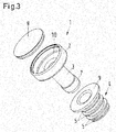
- FIG. 3 shows the items of a bottle closure 1 according to the invention for closing of beverage bottles, especially wine bottles, champagne bottles or spirits bottles, comprising a cap 2 with a cylindrical shaft 3, which extends centrally from the bottom 10 of the cap 2.
- both the cap 2 and the shaft 3 here essentially have a cylindrical basic shape. Both are connected to each other via a common cavity.
- the shaft 3 has the projection 7.
- the lid 8 has a watch-glass shape in this embodiment.
- the lamellar seal 4 is shown separately, which has a plurality of projecting annular, flexible, outwardly formed and concentrically arranged sealing lamellae 5.
- a flange-like sealing ring 9 is formed. This sealing ring 9 is intended to be brought into abutment after pushing the tubular plate seal 4 on the shaft 3 of the bottle closure 1 at the bottom of the bottom 10 of the cap 2.
- FIG. 4 an inventive bottle closure 1 is shown in a partial sectional view, wherein the sectional view in the right half of the illustration is shown starting from the central axis.
- the bottle cap 1 has a cap 2 with a cylindrical shaft 3, which extends centrally from the bottom 10 of the cap 2.
- the shaft 3 has at the opposite end of the bottom 10 of the cap 2 a flat termination 6.
- the cap 2 and the shaft 3 are integrally formed and form a common cavity.
- This unit can be made, for example, by injection molding from a single material, in particular plastic such as polycarbonate (PC), polystyrene (PS), HD-PE (polyethylene), SAN (styrene-acrylonitrile), PMMA (polymethyl methacrylate), PET (polyethylene terephthalate), ABS (acrylonitrile-butadiene-styrene copolymer) or the like, or a copolyester such as Tritan or others.
- the wall thickness of the cap 2, the shaft 3 and the closure 6 is here substantially identical and may be, for example, about 1.5 to 4 mm.
- a lid 8 is inserted, for example clipped, which has a disc shape here.
- Fig. 4 the lamellar seal 4 can be seen, which extends over the portion A of the length of the shaft 3.
- the portion A of the shaft 3 is limited at its upper end by the bottom 10 of the lid 2 and at its lower end by the projection 7 of the shaft 3.
- the lamellar seal 4 has at its upper end a flange-like sealing ring 9, which rests against the underside of the bottom 10 of the cap 2.
- the lamellar seal 4 here has, for example, four annular, flexible, outwardly formed and concentrically arranged sealing lamellae 5.
- the projection 7 immediately adjacent sealing lamella 5 has a slightly smaller outer diameter than the other three sealing lamellae 5.
- the lamellar seal 4 is, for example, a plastic, selected from the group consisting of LD-PE ("low density" polyethylene), EVA (ethylene vinyl acetate) and PP (polypropylene) manufactured.
- the projection 7 located on the end of the shaft 3 opposite the bottom 10 of the cap 2 is essentially a section-wise widening of the diameter of the cylindrical shaft 3. This projection 7 prevents the slat seal 4 from slipping on the shaft 3. This is achieved. in that the lamellar seal 4 strikes against the projection 7 on the one hand and against the bottom 10 of the cap 2 on the other hand.
- FIG. 5 is a section of a further embodiment of the bottle closure 1 to recognize, wherein the lamellar seal 4 separated from the bottle closure 1 is shown.
- the lamellar seal is closed at the opposite side of the bottom of the cap and feels the conical converging shape of the shaft 3 below the projection 7. If the plate seal 4 is mounted on the shaft 3, it encloses its end closely and is held by the own bias and by the circumferential groove 13 and the projection 7 on the shaft 3.
- the lamellar seal 4 rests with the flange-like sealing ring 9 on the bottom of the cap 10 and surrounds the shaft 3 completely.
- the portion A of the shaft 3 is limited at its upper end by the bottom 10 of the lid 2 and at its lower end by the end 6 of the shaft 3.
- the lamellar seal 4 is sprayed onto the shaft 3 with a two-component injection method, whereby the step of winding up the lamellar seal 4 over the shaft 3 is saved and a particularly secure hold is obtained.
Landscapes
- Engineering & Computer Science (AREA)
- Mechanical Engineering (AREA)
- Closures For Containers (AREA)
Applications Claiming Priority (1)
| Application Number | Priority Date | Filing Date | Title |
|---|---|---|---|
| DE102016102574.7A DE102016102574B3 (de) | 2016-02-15 | 2016-02-15 | Flaschenverschluss mit schlauchförmiger Lamellendichtung |
Publications (2)
| Publication Number | Publication Date |
|---|---|
| EP3205595A1 true EP3205595A1 (fr) | 2017-08-16 |
| EP3205595B1 EP3205595B1 (fr) | 2019-05-08 |
Family
ID=58046535
Family Applications (1)
| Application Number | Title | Priority Date | Filing Date |
|---|---|---|---|
| EP17156055.0A Active EP3205595B1 (fr) | 2016-02-15 | 2017-02-14 | Fermeture de bouteille comprenant un joint à lamelles tubulaire |
Country Status (2)
| Country | Link |
|---|---|
| EP (1) | EP3205595B1 (fr) |
| DE (1) | DE102016102574B3 (fr) |
Cited By (1)
| Publication number | Priority date | Publication date | Assignee | Title |
|---|---|---|---|---|
| PL443643A1 (pl) * | 2022-12-22 | 2024-06-24 | Baltic caps, UAB | Korek od butelki |
Families Citing this family (2)
| Publication number | Priority date | Publication date | Assignee | Title |
|---|---|---|---|---|
| DE102017209578A1 (de) | 2017-06-07 | 2018-12-13 | Hanon Systems | Gehäuse, insbesondere Filtergehäuse und Klimatisierungssystem für ein Fahrzeug |
| US11905071B2 (en) * | 2021-10-18 | 2024-02-20 | Ly Huy Sang | Auto-lock sealing valve structure of a rubber jointing ring in the containers using a lid attached to the rubber jointing ring |
Citations (14)
| Publication number | Priority date | Publication date | Assignee | Title |
|---|---|---|---|---|
| BE541495A (fr) * | ||||
| FR1030600A (fr) | 1949-08-04 | 1953-06-15 | Fermeture pour récipients | |
| US3074579A (en) | 1960-01-15 | 1963-01-22 | Formold Plastics Inc | Combination closure cap and stopper |
| FR2306896A1 (fr) | 1975-04-07 | 1976-11-05 | Grussen Jean | Nouvelle capsule a vis avec jonc de securite |
| DE2614538A1 (de) | 1976-04-03 | 1977-10-06 | Consumers Glass Co Ltd | Verschluss fuer eine flasche |
| DE2833099A1 (de) | 1978-07-28 | 1980-02-14 | Pfefferkorn & Co | Verschlusstopfen aus elastischem kunststoff |
| DE3008838A1 (de) | 1979-04-03 | 1980-10-16 | Wiedmer Plastikform W | Schraubverschluss fuer einen behaelter |
| DE3307592A1 (de) * | 1982-03-30 | 1983-10-13 | Yoshida Industry Co | Verfahren zum herstellen eines flaschenverschlusses und flaschenverschluss |
| EP0079552B1 (fr) | 1981-11-11 | 1985-05-22 | Bramlage GmbH | Fermeture pour bouteilles, notamment pour bouteilles de champagne |
| EP0308753A1 (fr) | 1987-09-24 | 1989-03-29 | PFEFFERKORN & CO GMBH | Capuchon à vis en particulier pour bouteilles de vin mousseux |
| DE29601568U1 (de) * | 1995-01-30 | 1996-05-09 | Billekens Bart | Flaschenverschluß |
| DE19616000A1 (de) * | 1996-04-10 | 1997-10-16 | Francesco Piero Macchi | Schraubstöpsel mit zentralem Dichtungsteil |
| US20120199588A1 (en) * | 2011-02-04 | 2012-08-09 | Lifetime Brands, Inc. | Expanding Sealing Locking Systems And Methods |
| DE202012006881U1 (de) | 2012-07-16 | 2012-08-09 | Pfefferkorn & Co Gmbh | Flaschenverschluss |
Family Cites Families (2)
| Publication number | Priority date | Publication date | Assignee | Title |
|---|---|---|---|---|
| DE29808195U1 (de) * | 1998-05-07 | 1999-09-16 | Seliger, Wolfgang, 94133 Röhrnbach | Flaschenstopfen |
| DE29819204U1 (de) * | 1998-10-28 | 1999-05-12 | Hutschenreuter Nicole | Wiederverwendbarer Sektverschluß |
-
2016
- 2016-02-15 DE DE102016102574.7A patent/DE102016102574B3/de not_active Expired - Fee Related
-
2017
- 2017-02-14 EP EP17156055.0A patent/EP3205595B1/fr active Active
Patent Citations (14)
| Publication number | Priority date | Publication date | Assignee | Title |
|---|---|---|---|---|
| BE541495A (fr) * | ||||
| FR1030600A (fr) | 1949-08-04 | 1953-06-15 | Fermeture pour récipients | |
| US3074579A (en) | 1960-01-15 | 1963-01-22 | Formold Plastics Inc | Combination closure cap and stopper |
| FR2306896A1 (fr) | 1975-04-07 | 1976-11-05 | Grussen Jean | Nouvelle capsule a vis avec jonc de securite |
| DE2614538A1 (de) | 1976-04-03 | 1977-10-06 | Consumers Glass Co Ltd | Verschluss fuer eine flasche |
| DE2833099A1 (de) | 1978-07-28 | 1980-02-14 | Pfefferkorn & Co | Verschlusstopfen aus elastischem kunststoff |
| DE3008838A1 (de) | 1979-04-03 | 1980-10-16 | Wiedmer Plastikform W | Schraubverschluss fuer einen behaelter |
| EP0079552B1 (fr) | 1981-11-11 | 1985-05-22 | Bramlage GmbH | Fermeture pour bouteilles, notamment pour bouteilles de champagne |
| DE3307592A1 (de) * | 1982-03-30 | 1983-10-13 | Yoshida Industry Co | Verfahren zum herstellen eines flaschenverschlusses und flaschenverschluss |
| EP0308753A1 (fr) | 1987-09-24 | 1989-03-29 | PFEFFERKORN & CO GMBH | Capuchon à vis en particulier pour bouteilles de vin mousseux |
| DE29601568U1 (de) * | 1995-01-30 | 1996-05-09 | Billekens Bart | Flaschenverschluß |
| DE19616000A1 (de) * | 1996-04-10 | 1997-10-16 | Francesco Piero Macchi | Schraubstöpsel mit zentralem Dichtungsteil |
| US20120199588A1 (en) * | 2011-02-04 | 2012-08-09 | Lifetime Brands, Inc. | Expanding Sealing Locking Systems And Methods |
| DE202012006881U1 (de) | 2012-07-16 | 2012-08-09 | Pfefferkorn & Co Gmbh | Flaschenverschluss |
Cited By (1)
| Publication number | Priority date | Publication date | Assignee | Title |
|---|---|---|---|---|
| PL443643A1 (pl) * | 2022-12-22 | 2024-06-24 | Baltic caps, UAB | Korek od butelki |
Also Published As
| Publication number | Publication date |
|---|---|
| EP3205595B1 (fr) | 2019-05-08 |
| DE102016102574B3 (de) | 2017-04-06 |
Similar Documents
| Publication | Publication Date | Title |
|---|---|---|
| EP0308753B1 (fr) | Capuchon à vis en particulier pour bouteilles de vin mousseux | |
| EP2723650B1 (fr) | Dispositif de fermeture remplissable permettant de declancher le vidage d'une capsule | |
| DE10297200B4 (de) | Verschluss für Behälteröffnungen | |
| EP2628689B1 (fr) | Fermeture push-pull pour un récipient de boisson | |
| CH716857A2 (de) | Behälterverschluss. | |
| EP3873821B1 (fr) | Bouchon de fermeture pour la fermeture d'un contenant | |
| WO2009138183A1 (fr) | Bouchon tire-pousse pour un contenant à boisson | |
| EP3205595B1 (fr) | Fermeture de bouteille comprenant un joint à lamelles tubulaire | |
| CH715953A2 (de) | Verschlusskappe zum Verschliessen eines Behälters und Behälter mit einer solchen unverlierbar gehaltenen Verschlusskappe. | |
| DE60107430T2 (de) | Druckstopfen für Flaschen und Ähnliches | |
| DE10308599A1 (de) | Verschlusskappe | |
| DE102004034709B3 (de) | Stopfen zum Verschließen einer Flasche | |
| EP1038468B1 (fr) | Element de produit cosmétique, en particulier mascara | |
| WO2021245218A1 (fr) | Fermeture de récipient | |
| DE69902567T2 (de) | Öffnungsvorrichtung | |
| DE202014003192U1 (de) | Vorrichtung zum Verschließen der Flaschen mit den Spirituosen | |
| EP3002228A1 (fr) | Fermeture de bouteille pour fermer une bouteille | |
| CH716074A1 (de) | Verschlusskappe zum Verschliessen eines Behälters und Behälter mit einer solchen unverlierbar gehaltenen Verschlusskappe. | |
| DE102005034178A1 (de) | Vorrichtung zum Aufbewahren von Flüssigkeit | |
| DE102007028158B3 (de) | Mehrweg-Verschlussstopfen für Wein-, Sekt- und Bierflaschen | |
| DE202012006881U1 (de) | Flaschenverschluss | |
| DE1914314A1 (de) | Ausdehnbarer Verschlussstoepsel | |
| EP0060983B1 (fr) | Récipient avec fermeture de sécurité | |
| DE102007029654B3 (de) | Flaschenverschluss mit Federscheibe | |
| EP2729380B1 (fr) | Fermeture pour contenants, en particulier pour bouteilles et récipients |
Legal Events
| Date | Code | Title | Description |
|---|---|---|---|
| PUAI | Public reference made under article 153(3) epc to a published international application that has entered the european phase |
Free format text: ORIGINAL CODE: 0009012 |
|
| STAA | Information on the status of an ep patent application or granted ep patent |
Free format text: STATUS: THE APPLICATION HAS BEEN PUBLISHED |
|
| AK | Designated contracting states |
Kind code of ref document: A1 Designated state(s): AL AT BE BG CH CY CZ DE DK EE ES FI FR GB GR HR HU IE IS IT LI LT LU LV MC MK MT NL NO PL PT RO RS SE SI SK SM TR |
|
| AX | Request for extension of the european patent |
Extension state: BA ME |
|
| STAA | Information on the status of an ep patent application or granted ep patent |
Free format text: STATUS: REQUEST FOR EXAMINATION WAS MADE |
|
| 17P | Request for examination filed |
Effective date: 20171211 |
|
| RBV | Designated contracting states (corrected) |
Designated state(s): AL AT BE BG CH CY CZ DE DK EE ES FI FR GB GR HR HU IE IS IT LI LT LU LV MC MK MT NL NO PL PT RO RS SE SI SK SM TR |
|
| STAA | Information on the status of an ep patent application or granted ep patent |
Free format text: STATUS: EXAMINATION IS IN PROGRESS |
|
| 17Q | First examination report despatched |
Effective date: 20180309 |
|
| GRAP | Despatch of communication of intention to grant a patent |
Free format text: ORIGINAL CODE: EPIDOSNIGR1 |
|
| STAA | Information on the status of an ep patent application or granted ep patent |
Free format text: STATUS: GRANT OF PATENT IS INTENDED |
|
| INTG | Intention to grant announced |
Effective date: 20181128 |
|
| GRAS | Grant fee paid |
Free format text: ORIGINAL CODE: EPIDOSNIGR3 |
|
| GRAA | (expected) grant |
Free format text: ORIGINAL CODE: 0009210 |
|
| STAA | Information on the status of an ep patent application or granted ep patent |
Free format text: STATUS: THE PATENT HAS BEEN GRANTED |
|
| AK | Designated contracting states |
Kind code of ref document: B1 Designated state(s): AL AT BE BG CH CY CZ DE DK EE ES FI FR GB GR HR HU IE IS IT LI LT LU LV MC MK MT NL NO PL PT RO RS SE SI SK SM TR |
|
| REG | Reference to a national code |
Ref country code: GB Ref legal event code: FG4D Free format text: NOT ENGLISH |
|
| REG | Reference to a national code |
Ref country code: CH Ref legal event code: EP Ref country code: AT Ref legal event code: REF Ref document number: 1129786 Country of ref document: AT Kind code of ref document: T Effective date: 20190515 |
|
| REG | Reference to a national code |
Ref country code: DE Ref legal event code: R096 Ref document number: 502017001235 Country of ref document: DE |
|
| REG | Reference to a national code |
Ref country code: IE Ref legal event code: FG4D Free format text: LANGUAGE OF EP DOCUMENT: GERMAN |
|
| REG | Reference to a national code |
Ref country code: NL Ref legal event code: MP Effective date: 20190508 |
|
| REG | Reference to a national code |
Ref country code: LT Ref legal event code: MG4D |
|
| PG25 | Lapsed in a contracting state [announced via postgrant information from national office to epo] |
Ref country code: AL Free format text: LAPSE BECAUSE OF FAILURE TO SUBMIT A TRANSLATION OF THE DESCRIPTION OR TO PAY THE FEE WITHIN THE PRESCRIBED TIME-LIMIT Effective date: 20190508 Ref country code: ES Free format text: LAPSE BECAUSE OF FAILURE TO SUBMIT A TRANSLATION OF THE DESCRIPTION OR TO PAY THE FEE WITHIN THE PRESCRIBED TIME-LIMIT Effective date: 20190508 Ref country code: PT Free format text: LAPSE BECAUSE OF FAILURE TO SUBMIT A TRANSLATION OF THE DESCRIPTION OR TO PAY THE FEE WITHIN THE PRESCRIBED TIME-LIMIT Effective date: 20190908 Ref country code: SE Free format text: LAPSE BECAUSE OF FAILURE TO SUBMIT A TRANSLATION OF THE DESCRIPTION OR TO PAY THE FEE WITHIN THE PRESCRIBED TIME-LIMIT Effective date: 20190508 Ref country code: NO Free format text: LAPSE BECAUSE OF FAILURE TO SUBMIT A TRANSLATION OF THE DESCRIPTION OR TO PAY THE FEE WITHIN THE PRESCRIBED TIME-LIMIT Effective date: 20190808 Ref country code: HR Free format text: LAPSE BECAUSE OF FAILURE TO SUBMIT A TRANSLATION OF THE DESCRIPTION OR TO PAY THE FEE WITHIN THE PRESCRIBED TIME-LIMIT Effective date: 20190508 Ref country code: LT Free format text: LAPSE BECAUSE OF FAILURE TO SUBMIT A TRANSLATION OF THE DESCRIPTION OR TO PAY THE FEE WITHIN THE PRESCRIBED TIME-LIMIT Effective date: 20190508 Ref country code: NL Free format text: LAPSE BECAUSE OF FAILURE TO SUBMIT A TRANSLATION OF THE DESCRIPTION OR TO PAY THE FEE WITHIN THE PRESCRIBED TIME-LIMIT Effective date: 20190508 Ref country code: FI Free format text: LAPSE BECAUSE OF FAILURE TO SUBMIT A TRANSLATION OF THE DESCRIPTION OR TO PAY THE FEE WITHIN THE PRESCRIBED TIME-LIMIT Effective date: 20190508 |
|
| PG25 | Lapsed in a contracting state [announced via postgrant information from national office to epo] |
Ref country code: LV Free format text: LAPSE BECAUSE OF FAILURE TO SUBMIT A TRANSLATION OF THE DESCRIPTION OR TO PAY THE FEE WITHIN THE PRESCRIBED TIME-LIMIT Effective date: 20190508 Ref country code: RS Free format text: LAPSE BECAUSE OF FAILURE TO SUBMIT A TRANSLATION OF THE DESCRIPTION OR TO PAY THE FEE WITHIN THE PRESCRIBED TIME-LIMIT Effective date: 20190508 Ref country code: BG Free format text: LAPSE BECAUSE OF FAILURE TO SUBMIT A TRANSLATION OF THE DESCRIPTION OR TO PAY THE FEE WITHIN THE PRESCRIBED TIME-LIMIT Effective date: 20190808 Ref country code: GR Free format text: LAPSE BECAUSE OF FAILURE TO SUBMIT A TRANSLATION OF THE DESCRIPTION OR TO PAY THE FEE WITHIN THE PRESCRIBED TIME-LIMIT Effective date: 20190809 |
|
| PG25 | Lapsed in a contracting state [announced via postgrant information from national office to epo] |
Ref country code: SK Free format text: LAPSE BECAUSE OF FAILURE TO SUBMIT A TRANSLATION OF THE DESCRIPTION OR TO PAY THE FEE WITHIN THE PRESCRIBED TIME-LIMIT Effective date: 20190508 Ref country code: EE Free format text: LAPSE BECAUSE OF FAILURE TO SUBMIT A TRANSLATION OF THE DESCRIPTION OR TO PAY THE FEE WITHIN THE PRESCRIBED TIME-LIMIT Effective date: 20190508 Ref country code: DK Free format text: LAPSE BECAUSE OF FAILURE TO SUBMIT A TRANSLATION OF THE DESCRIPTION OR TO PAY THE FEE WITHIN THE PRESCRIBED TIME-LIMIT Effective date: 20190508 Ref country code: RO Free format text: LAPSE BECAUSE OF FAILURE TO SUBMIT A TRANSLATION OF THE DESCRIPTION OR TO PAY THE FEE WITHIN THE PRESCRIBED TIME-LIMIT Effective date: 20190508 Ref country code: CZ Free format text: LAPSE BECAUSE OF FAILURE TO SUBMIT A TRANSLATION OF THE DESCRIPTION OR TO PAY THE FEE WITHIN THE PRESCRIBED TIME-LIMIT Effective date: 20190508 |
|
| REG | Reference to a national code |
Ref country code: DE Ref legal event code: R097 Ref document number: 502017001235 Country of ref document: DE |
|
| PG25 | Lapsed in a contracting state [announced via postgrant information from national office to epo] |
Ref country code: IT Free format text: LAPSE BECAUSE OF FAILURE TO SUBMIT A TRANSLATION OF THE DESCRIPTION OR TO PAY THE FEE WITHIN THE PRESCRIBED TIME-LIMIT Effective date: 20190508 Ref country code: SM Free format text: LAPSE BECAUSE OF FAILURE TO SUBMIT A TRANSLATION OF THE DESCRIPTION OR TO PAY THE FEE WITHIN THE PRESCRIBED TIME-LIMIT Effective date: 20190508 |
|
| PLBE | No opposition filed within time limit |
Free format text: ORIGINAL CODE: 0009261 |
|
| STAA | Information on the status of an ep patent application or granted ep patent |
Free format text: STATUS: NO OPPOSITION FILED WITHIN TIME LIMIT |
|
| PG25 | Lapsed in a contracting state [announced via postgrant information from national office to epo] |
Ref country code: TR Free format text: LAPSE BECAUSE OF FAILURE TO SUBMIT A TRANSLATION OF THE DESCRIPTION OR TO PAY THE FEE WITHIN THE PRESCRIBED TIME-LIMIT Effective date: 20190508 |
|
| 26N | No opposition filed |
Effective date: 20200211 |
|
| PG25 | Lapsed in a contracting state [announced via postgrant information from national office to epo] |
Ref country code: PL Free format text: LAPSE BECAUSE OF FAILURE TO SUBMIT A TRANSLATION OF THE DESCRIPTION OR TO PAY THE FEE WITHIN THE PRESCRIBED TIME-LIMIT Effective date: 20190508 |
|
| PGFP | Annual fee paid to national office [announced via postgrant information from national office to epo] |
Ref country code: DE Payment date: 20200229 Year of fee payment: 4 |
|
| PG25 | Lapsed in a contracting state [announced via postgrant information from national office to epo] |
Ref country code: SI Free format text: LAPSE BECAUSE OF FAILURE TO SUBMIT A TRANSLATION OF THE DESCRIPTION OR TO PAY THE FEE WITHIN THE PRESCRIBED TIME-LIMIT Effective date: 20190508 |
|
| PGFP | Annual fee paid to national office [announced via postgrant information from national office to epo] |
Ref country code: FR Payment date: 20200219 Year of fee payment: 4 |
|
| REG | Reference to a national code |
Ref country code: CH Ref legal event code: PL |
|
| REG | Reference to a national code |
Ref country code: BE Ref legal event code: MM Effective date: 20200229 |
|
| PG25 | Lapsed in a contracting state [announced via postgrant information from national office to epo] |
Ref country code: LU Free format text: LAPSE BECAUSE OF NON-PAYMENT OF DUE FEES Effective date: 20200214 Ref country code: MC Free format text: LAPSE BECAUSE OF FAILURE TO SUBMIT A TRANSLATION OF THE DESCRIPTION OR TO PAY THE FEE WITHIN THE PRESCRIBED TIME-LIMIT Effective date: 20190508 |
|
| PG25 | Lapsed in a contracting state [announced via postgrant information from national office to epo] |
Ref country code: LI Free format text: LAPSE BECAUSE OF NON-PAYMENT OF DUE FEES Effective date: 20200229 Ref country code: CH Free format text: LAPSE BECAUSE OF NON-PAYMENT OF DUE FEES Effective date: 20200229 |
|
| PG25 | Lapsed in a contracting state [announced via postgrant information from national office to epo] |
Ref country code: IE Free format text: LAPSE BECAUSE OF NON-PAYMENT OF DUE FEES Effective date: 20200214 |
|
| PG25 | Lapsed in a contracting state [announced via postgrant information from national office to epo] |
Ref country code: BE Free format text: LAPSE BECAUSE OF NON-PAYMENT OF DUE FEES Effective date: 20200229 |
|
| REG | Reference to a national code |
Ref country code: DE Ref legal event code: R119 Ref document number: 502017001235 Country of ref document: DE |
|
| GBPC | Gb: european patent ceased through non-payment of renewal fee |
Effective date: 20210214 |
|
| PG25 | Lapsed in a contracting state [announced via postgrant information from national office to epo] |
Ref country code: DE Free format text: LAPSE BECAUSE OF NON-PAYMENT OF DUE FEES Effective date: 20210901 Ref country code: FR Free format text: LAPSE BECAUSE OF NON-PAYMENT OF DUE FEES Effective date: 20210228 Ref country code: GB Free format text: LAPSE BECAUSE OF NON-PAYMENT OF DUE FEES Effective date: 20210214 |
|
| PG25 | Lapsed in a contracting state [announced via postgrant information from national office to epo] |
Ref country code: MT Free format text: LAPSE BECAUSE OF FAILURE TO SUBMIT A TRANSLATION OF THE DESCRIPTION OR TO PAY THE FEE WITHIN THE PRESCRIBED TIME-LIMIT Effective date: 20190508 Ref country code: CY Free format text: LAPSE BECAUSE OF FAILURE TO SUBMIT A TRANSLATION OF THE DESCRIPTION OR TO PAY THE FEE WITHIN THE PRESCRIBED TIME-LIMIT Effective date: 20190508 |
|
| PG25 | Lapsed in a contracting state [announced via postgrant information from national office to epo] |
Ref country code: MK Free format text: LAPSE BECAUSE OF FAILURE TO SUBMIT A TRANSLATION OF THE DESCRIPTION OR TO PAY THE FEE WITHIN THE PRESCRIBED TIME-LIMIT Effective date: 20190508 Ref country code: IS Free format text: LAPSE BECAUSE OF FAILURE TO SUBMIT A TRANSLATION OF THE DESCRIPTION OR TO PAY THE FEE WITHIN THE PRESCRIBED TIME-LIMIT Effective date: 20190908 |
|
| REG | Reference to a national code |
Ref country code: AT Ref legal event code: MM01 Ref document number: 1129786 Country of ref document: AT Kind code of ref document: T Effective date: 20220214 |
|
| PG25 | Lapsed in a contracting state [announced via postgrant information from national office to epo] |
Ref country code: AT Free format text: LAPSE BECAUSE OF NON-PAYMENT OF DUE FEES Effective date: 20220214 |