EP3205771B1 - Verfahren zur bestimmung der verschiebungen einer schiene eines bahngleises im absoluten bereich - Google Patents
Verfahren zur bestimmung der verschiebungen einer schiene eines bahngleises im absoluten bereich Download PDFInfo
- Publication number
- EP3205771B1 EP3205771B1 EP17155780.4A EP17155780A EP3205771B1 EP 3205771 B1 EP3205771 B1 EP 3205771B1 EP 17155780 A EP17155780 A EP 17155780A EP 3205771 B1 EP3205771 B1 EP 3205771B1
- Authority
- EP
- European Patent Office
- Prior art keywords
- rail
- sub
- frequency
- absolute
- versine
- Prior art date
- Legal status (The legal status is an assumption and is not a legal conclusion. Google has not performed a legal analysis and makes no representation as to the accuracy of the status listed.)
- Active
Links
Images

Classifications
-
- E—FIXED CONSTRUCTIONS
- E01—CONSTRUCTION OF ROADS, RAILWAYS, OR BRIDGES
- E01B—PERMANENT WAY; PERMANENT-WAY TOOLS; MACHINES FOR MAKING RAILWAYS OF ALL KINDS
- E01B35/00—Applications of measuring apparatus or devices for track-building purposes
- E01B35/06—Applications of measuring apparatus or devices for track-building purposes for measuring irregularities in longitudinal direction
-
- E—FIXED CONSTRUCTIONS
- E01—CONSTRUCTION OF ROADS, RAILWAYS, OR BRIDGES
- E01B—PERMANENT WAY; PERMANENT-WAY TOOLS; MACHINES FOR MAKING RAILWAYS OF ALL KINDS
- E01B33/00—Machines or devices for shifting tracks, with or without lifting, e.g. for aligning track, for shifting excavator track
- E01B33/02—Machines or devices for shifting tracks, with or without lifting, e.g. for aligning track, for shifting excavator track for slewing, i.e. transversely shifting, in steps
Definitions
- the present invention belongs to the field of roadway maintenance for guided transport systems. It relates more particularly to a method for determining shifts of a rail of a railway in absolute domain. The present invention finds a particularly advantageous application, although in no way limiting, in the maintenance of the railway tracks.
- railway rails which provide both transverse guidance and vertical support trains, are subject to various constraints that can affect their structure, and therefore a fortiori their trajectory.
- such displacements are determined by means of a method comprising a preliminary step of determining geometrical parameters characteristic of the curvature of said rail, as well as a step of calculating displacements to be imposed at points of said rail, called points. of control, in order to calibrate these geometric parameters on corresponding values of a reference profile, generally archived during the laying of the railway.
- said arrows are determined along the rail by means of a measuring device, such as a lorry.
- a measuring device such as a lorry.
- the latter is comparable to a mechanical system comprising an input signal and an output signal which are respectively a representation of the intrinsic geometry of the rail along which it moves and said arrows raised, these input and output signals being mapped by means of a transfer function.
- the present invention aims to overcome all or part of the disadvantages of the prior art, including those described above, by proposing a method that makes it possible to determine the shifts of a rail of a railway in absolute domain and which presents steps adapted to the calculation of the shifts from a faithful representation of the rail, as well as to the taking into account in the calculation of said shifts of defects of the rail distributed over an extended spectrum (wavelengths of the order from the meter to wavelengths of the order of a hundred meters) through the use of several transfer functions.
- the invention relates to a method for determining shifts of a track rail in absolute domain, said rail being comparable to a curve sampled at successive control points in which arrows were obtained by means of a number N of transfer functions that are distinct from each other, N being greater than or equal to 1, and each arrow being associated with only one of said transfer functions so as to form N sets of arrows.
- the method for determining shifts of an absolute domain track rail comprises one or more of the following characteristics, taken separately or in any technically possible combination.
- said decomposition of the absolute profile estimated according to the intended route of the rail and the training of the rail is obtained from a predetermined frequency filtering of said absolute profile estimated according to a first frequency window and a second window, respectively. frequency, each of said frequency windows having a lower terminal and an upper terminal.
- said first and second frequency windows are respectively a first wavelength interval and a second wavelength interval, the upper bound and the lower bound respectively of said first interval and said second interval. being equal to a terminal slaved to the curvilinear abscissa along the rail as well as to a predetermined value of slippage corridor.
- a threshold value is associated with each frequency sub-window during said sub-step of frequency filtering, each of said frequency sub-windows further comprising a lower bound and an upper bound determining a frequency range. during which the variation of the module of said inverse transfer function associated with said frequency sub-window is bounded around 1 by said threshold value.
- the respective lower and upper bounds of said frequency sub-windows are determined iteratively so that the meeting of said frequency sub-windows describe a continuous frequency spectrum similar to the spectrum of the rail.
- said filtered intermediate absolute profiles are summed frequency component by frequency component during said substep of recomposition of said estimated absolute profile.
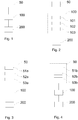
- the figure 1 represents a flowchart of an example of implementation of a method for determining shifts of a rail of a railway in absolute domain.
- the invention specifically targets a railway rail, but remains applicable to all types of rails, including those of guided transport systems intended to circulate on a monorail or multirail network.
- a railway is a double rail network. Therefore, said invention applies to any one of the two rails of said railway, without loss of generality, and it being understood that once shifts determined for one of said two rails (preferably the rail of larger radius for the skilled person insofar as said rail of larger radius is in practice the curved guide rail), these shifts are also connectable to the other of said two rails thanks to the knowledge of the rail between said two rails .
- each point of said rail curve is associated, in a manner known per se, with a Frenet marker comprising, on the one hand, a unit vector tangent to said curve at said point, and secondly a unit vector normal to said tangent vector.
- the left and right sides of said rail are defined as being the sides situated on the left and the right of any guided transport system traveling along the rail in the direction of the mileage, from said first end to said second end.
- the distance between two points of said curve is in the sense of the length of the segment connecting said two points.
- said distance is differentiated from the curvilinear distance separating said two points, the latter being counted along the curve of the rail by means of the curvilinear abscissa s originating from one of said two points.
- said signal R (X) does not correspond to an explicit representation of the rail curve, which can still be formulated from a point of mathematical view by observing that said function R (X) is multivalued, or else unequivocal (still differently, there is at least one line parallel to the Y-axis and intersecting the rail curve in at least 2 points) . It is known to those skilled in the art that such a representation is disadvantageous when it is important to study the geometry of the rail from a numerical point of view.
- a parameterization of the rail curve is defined in the form of a signal (in other words a digital function) denoted Y t depending on the curvilinear abscissa along the rail curve.
- Y t ⁇ ⁇ C s d s 2
- Such a parameterization of the rail curve is well known to those skilled in the art and has the advantage of being explicit, that is to say that the function Y t ( s ) is monovalued, or univocal.
- the function Y t ( s ) is defined only from Euclidean invariants which are respectively the curvilinear abscissa along the curve of the rail and the curvature of said curve.
- This parameterization of the rail is therefore qualified as intrinsic absolute because it constitutes a representation of the geometry of the rail which is independent of its orientation in said longitudinal plane.
- said intrinsic absolute parameterization is called the absolute profile of the rail.
- said absolute profile is conventionally represented in an orthogonal coordinate system having for abscissa s and for ordinate Y t ( s ), and said absolute orthogonal reference.
- an arrow is also defined at a given point of the rail, referred to as the point of the arrow, as being the distance between said point of the arrow and an auxiliary point of a chord, of predefined length, underlying a subset of said rail containing said point of the arrow.
- said auxiliary point of the chord is the projection, on said chord, of the point of the arrow in the direction of the normal vector of the Frenet mark associated with said point of the arrow (which is still the direction along the ordinate of the mark of Frenet).
- Said arrow is an algebraic measurement, that is to say a length with a positive or negative sign depending on whether the point of deflection is, conventionally, located on an element of the curve of the rail whose center of curvature is positioned respectively to the right or left of the rail.
- said deflection also contributes to the characterization of the geometry of the rail insofar as its direction of variation, with respect to the position of the point of the arrow along the rail, is identical to that of the curvature, as described herein. -before.
- the rope used to determine an arrow is of suitable length so that the two points of the rail positioned at the intersection of the rope and said rail, said points. adjacent, are equidistant from said point of the arrow of 10m (accordingly the rope has a length less than 20m).
- Such a configuration is conventionally used in railway engineering, that is to say known to those skilled in the art, and is advantageous when, for example, a cord is used to measure the arrows in the field, the latter not being subjected to when no significant deformations under the effect of its weight.
- chord length for example with a chord length of 10m and adjacent points positioned, in no way limiting, equidistant from the point of the arrow.
- said point of the arrow is not equidistant from said adjacent points.
- An arrow is measured (or, equivalently, read) by measuring means known to those skilled in the art, whose operation may be automatic, such as for example linear displacement sensors, or requiring human intervention.
- the measurement of the deflection is therefore dependent on the geometry of the rail, but also above all on said measuring means used and their displacements along the rail so that it provides a parametrization of the rail described as relative, as opposed to the absolute profile described above.
- the absolute profile and the arrows measured along the rail are matched in this order by means of a characteristic transfer function of said measurement means implemented.
- the absolute profile of the rail constitutes an input signal of the measuring means, said transfer function performing mathematical operations from characteristic geometrical quantities of said absolute profile so as to provide an output signal of said measuring means, namely, said arrows.
- said arrow signal is a function of the curvilinear abscissa along the rail curve.
- Said arrows signal is conventionally represented in an orthogonal coordinate system having the abscissa s and ordinate the value of the arrow, and said orthogonal reference arrows.
- a signal is a digital function that satisfies the necessary and sufficient conditions (regularity, periodicity) to harmonic development.
- sinusoidal said harmonics ranging from low to high frequencies (respectively equivalently, large to small wavelengths) in a predetermined pitch, each of said sinusoidal harmonics being further characterized by its amplitude and phase.
- the expression "frequential component" is also used instead of that of sinusoidal harmonic without this leading to confusion.
- the fact of being in harmonic regime with respect to the description of signals is equivalent in a manner known to those skilled in the art to describe them in frequency regime.
- the absolute profile of the rail (respectively the arrow signal) is a continuous function extending between said first and second ends of the rail, this function can also be defined as the restriction of a periodic function of period equal to the length of the rail.
- the absolute profile of the rail (respectively the signal of arrows) satisfies the conditions necessary and sufficient for development in sinusoidal harmonics.
- said measuring means matching the absolute profile of the rail with the arrows signal, are linear systems, continuous and invariant so that an output signal is a linear function of the signal of associated with it, and that the superposition principle applies.
- Said auxiliary rope being defined so that its projection on the abscissa axis s in the absolute orthogonal coordinate system is of length L, and that its two ends project on the abscissa axis s at two respective abscissa points equal to curvilinear abscissa of said two adjacent points.
- the absolute profile Y t ( s ) is an advantageous representation of the rail and its geometry. More particularly, the link between said absolute profile and the measurements of arrows along the rail, as explained above, means that "determination of shifts in absolute domain" the determination of shifts of said absolute profile Y t ( s ), these shifts being intended to vary the amplitude of said absolute profile Y t ( s ) so as to correct the defects of the rail.
- shifting corridor corresponds to the maximum permissible deviation between shifts made respectively on the left and on the right of the rail.
- Said corridor of shifts is typically a technical constraint set by a rail maintenance operator in order to respect, for example, template constraints and obstacles imposed on said rail.
- the curve of the rail is sampled at successive control points in which arrows have previously been obtained by means of a number N of transfer functions that are distinct from one another, N being greater than or equal to 1, and each arrow being associated to only one of said transfer functions so as to form N sets of arrows.
- these two transfer functions are respectively associated with two different measurement means, such as, for example, and by no means limiting, two lorries.
- any means for measuring arrows is characterized by the length of rope used as well as by the relative position of an arrow point with respect to the points adjacent to said point of arrow.
- the present invention is described with only theoretical limitation that an arrow point can not be confused with an adjacent point associated with it. This amounts to saying that, for each measuring means, said length of rope as well as said relative position of the arrow point, excluding adjacent points, are a priori left free.
- there are configurations of the measuring means having known characteristics and, in some cases, sought by those skilled in the art.
- the transfer function of said measuring means has a zero phase shift.
- the transfer function of said measuring means has a non-zero phase shift.
- the use of transfer functions having a zero phase shift or constant, of module with isolated zeros as well as decreasing slowly at long wavelengths is advantageous.
- said control points are physically embodied on the railway by means of visually identifiable marks, such as, for example, terminals installed during the laying of said railway, and are intended to locate the locations. where the rail will be rectified by means of an arrow modification, thus of a shifting, said locations being therefore coincident with the arrow points as defined above.
- the location of the control points is achieved by means of the measuring device described in the patent application. FR 14 50897 of the plaintiff.
- the method of determining shifts in absolute domain comprises firstly a step 50, following the obtaining of the arrows at said control points of the rail, modeling the rail by a signal said absolute profile estimated by means of said arrows obtained.
- a method of estimating the absolute profile of the rail adapted to the determination, for a transfer function associated with measuring means, of an inverse transfer function so that the application of said function reverse transfer to said arrows obtained provides a fair and accurate estimate of the absolute profile of the rail.
- step 50 of modeling the rail with an estimated absolute profile is assumed available at any time a database comprising the control points along the rail curve, arrows at said points control and distributed according to N sets of arrows, N transfer functions as well as the estimated absolute profile of the rail.
- N transfer functions are all distinct since they are associated with different measuring means, so that among said N transfer functions, there exists one and only one, so-called pass-through function, having a cut-off frequency higher than the respective cut-off frequencies of the other functions of transfer.
- the only transfer function used in step 50 is also said pass-through function.
- the improved operating conditions of the rail relate to the safety of movement of guided transports along the rail at prescribed speed as well as the comfort of passengers of said transport systems guided according to a set of standards, including in particular the standard NF EN 13848 -1.
- the rail dressing meanwhile, is representative of rail defects that oppose the respect of safety conditions, and to a lesser extent the respect of user comfort.
- said decomposition of the estimated absolute profile according to the intended route of the rail and the rail dressing is obtained from a predetermined frequency filtering of said absolute profile estimated according to a first frequency window respectively. and a second frequency window, each of said first and second frequency windows having a lower bound and an upper bound.
- Said frequency filtering according to said first and second frequency windows thus corresponds respectively to a first and second band-pass filtering of the estimated absolute profile, so as to isolate the contributions of wavelengths, respectively contained in said frequency windows, to the amplitude. and at the phase of said estimated absolute profile.
- said first and second frequency windows are respectively a first wavelength interval [3m, 70m] and a second wavelength interval [70m, 150m], so that the terminal of said first wavelength interval is equal to the lower limit of said second wavelength interval wavelengths.
- the intended alignment of the rail is decomposed according to a sum of sinusoidal harmonics, the latter being of respective wavelengths between 3m and 70m (respectively between 70m and 150m), as well as of amplitudes and phases identical respectively to the amplitudes and phases of the sinusoidal harmonics of the estimated absolute profile having the same wavelengths. It is therefore understandable that the algebraic sum of the sinusoidal harmonics of the target layout and of the training corresponds to the development in sinusoidal harmonics of the estimated absolute profile.
- the first wavelength interval can be separated into two sub-intervals which are respectively [3m, 25m] and [25m, 70m], so as to isolate with precision, if the maintenance of the rail requires it, sinusoidal harmonics of wavelengths between 3m and 25m representative of defects particularly problematic from the point of view of safety standards.
- said first and second frequency windows are respectively a first wavelength interval and a second wavelength interval of which the upper and lower limits respectively are equal.
- the frequency filtering of the estimated absolute profile is done by successive elements of the rail.
- said elements are a priori of different geometrical nature, and moreover they each have their own defects, said slave terminal is a fortiori different depending on whether it is associated with such or such element of the rail.
- the train of the rail is a signal function of the abscissa curvilinear and defined in pieces, each piece being associated with an element, so that said signal comprises discontinuities between two consecutive pieces. Therefore, it is known to those skilled in the art that said training can be made continuous by means of linear interpolation two consecutive pieces having a discontinuity, which is actually achieved.
- step 100 is particularly advantageous insofar as it constitutes an adaptive band-pass filtering, that is to say that it makes it possible to select for each element of the rail frequency window terminals adapted to better isolate the rail defects.
- the figure 2 represents another particular embodiment of the method of the figure 1 during which, during step 100, the target route is obtained by deconvolution of a rail outline, and the training is obtained by frequency filtering of intermediate training obtained as for him by difference between said estimated absolute profile and said intended route.
- a rail outline is mapped to the absolute profile of said rail by means of a transfer function, said transfer function being associated with measuring means. used when laying the rail to raise said outline.
- the measuring means used to provide a rail outline are pure 3-point type, with a length of 20m cord and the point of the arrow positioned equidistant from said adjacent points, so that the transfer function and the function of inverse transfer associated with said measuring means are known analytically.
- the transfer function and the inverse transfer function associated with the means for measuring a rail outline are assumed to be known.
- step 100 is broken down into several successive sub-steps.
- step 100 comprises a sub-step 101 for determining the target plot by applying to a rail outline a reverse transfer function of the transfer function associated with said rail outline.
- said target route is therefore different from the estimated absolute profile, and is representative of the intrinsic geometry of the rail during the laying of the railway.
- Step 100 then comprises a sub-step 102 for determining an intermediate dressing by difference between said estimated absolute profile and said target plot.
- Said intermediate dressing is a signal representative of the variations experienced by the rail over time due to its operation. In other words, he represents the variation of intrinsic geometry of the rail between the laying date of the rail and a date subsequent to said rail laying date. It should be noted, however, that the frequency spectrum of intermediate training is as extensive as that of the target route, or even the estimated absolute profile. This means in particular that said intermediate dressing comprises sinusoidal harmonics whose frequency is not representative of characteristic frequencies of rail defects as sought by those skilled in the art.
- step 100 comprises a sub-step 103 for determining said rail dressing by frequency filtering said intermediate dressing.
- said frequency filtering is effected by means of a frequency window so as to isolate rail defects considered to be of interest in order to correct the rail at the same time. medium of shifts.
- said frequency filtering corresponds to a bandpass filtering.
- said frequency window corresponds to a range of wavelengths [3m, 70m] or even [3m, 25m] as described above.
- the upper limit of said frequency window is determined according to the same technical characteristics as those described above in said preferred embodiment of step 100.
- step 100 is thus available the intended route of the rail representative rail track as desired under improved operating conditions. Also available is the rail dressing which reflects the defects of the rail, that is to say the deformations undergone by the latter over time and which, once added to said plot in the algebraic sense of the term, provide the profile absolute rail estimate as calculated in said step 50.
- the method for determining shifts in absolute domain finally comprises a step 200 of determining at said control points of shifts so that at each checkpoint the sum of said shifting and the rail dressing is zero.
- the determination of said shifts initially consists in creating a function called shifts function as being the opposite, in the algebraic sense of the term, of the shifts. rail dressing.
- Said rail dressing being a function of the curvilinear abscissa
- the function of shifts is obtained by multiplying said dressing by -1 so that at each point of the curvilinear abscissa along the rail, the sum of the dressing and the shifts function is zero.
- the determination of the shifts at said control points is given by the value of said shifted function evaluated at the curvilinear abscissa of said control points.
- Such a way of determining the shifts to said control points is advantageous because it is performed from a true geometric description of the rail, namely the estimated absolute profile of the latter. It is therefore an advantage over traditional methods of determining shifts, such as the Hallade method, in which shifts are calculated from arrow values which are a relative and not absolute parameterization of the rail. , said arrows being further obtained by applying at least one measuring means transfer function to the absolute profile of the rail.
- the expression of said at least one transfer function used during said traditional methods of determining shifts is based on the measurement principle as theoretically implemented by said measuring means, moving away and the empirical reality resulting from the mechanical stresses experienced by said measuring means.
- said at least one transfer function is that known to those skilled in the art, a device type 3 pure points.
- step 200 the shifts obtained at the end of step 200 have been advantageously calculated from the estimated absolute profile describing accurately the rail as laid on the track, and not from its representation by means of arrows.
- Such a way of proceeding makes it possible to gain in precision (of the order of the millimeter) in the determination of the values of the shifts.
- the mathematical operation for determining the shifts from the estimated absolute profile is simple to perform insofar as it consists in taking the opposite of the rail dressing. This is again an advantage in terms of time-consuming iterative calculations made within traditional methods (a slip at a fixed control point of the rail being dependent on the values of the arrows at all the other control points located on either side of said fixed control point).
- the determination of shifts as described in step 200 is advantageous because it makes it possible to correct the defects of the rail so that the position of the latter before and after correction of defects is not changed.
- This allows in particular to respect the constraints of templates as well as obstacles imposed on the railway.
- the periodicity of said sinusoidal harmonics implies that for the rail dressing to be canceled, the shifts are uniformly distributed to the left and right of the rail .
- the shifts are algebraic distances, we deduce that the sum of the shifts to the right of the rail is equal to the inverse of the sum of the shifts to the left of the rail.
- the process is adapted to have as many shifts to the right of the rail as to the left of the rail.
- step 200 in another embodiment of step 200, and when it is not necessary to obtain a shifts function to determine shifts at points other than said control points by continuity of said function of shifts, the shifts are determined directly from the values of the rail dressing at said control points multiplied by -1.
- This way of proceeding proves advantageous in the optics of a saving of time of computation since the function of shifts whole is not calculated.
- an estimate of the shifting function can be obtained later, without making use of rail dressing, by interpolating said shifts determined at the control points of the rail (linear interpolation, splines, etc.). The quality of this estimate is conventionally dependent on the sampling rate of the rail at said control points.
- the figure 3 represents a preferred embodiment of the method of figure 1 during which, in step 50, the estimated absolute profile of the rail is modeled by arrows taken along the rail by means of a number N of transfer functions, N being strictly greater than 1.
- step 50 is broken down into several successive sub-steps.
- step 50 comprises a substep 51a for estimating N intermediate absolute profiles by applying to each set of arrows a reverse transfer function of the transfer function associated with said set of arrows.
- Each inverse transfer function is for example determined by means of the absolute profile estimation method described in the patent application. EP 2,806,065 .
- Each of said N intermediate absolute profiles provides an approximation of the real absolute profile of the rail, the differences between these N intermediate absolute profiles resulting from the differences between the N transfer functions, and therefore N inverse transfer functions, to which they are respectively associated. That said N transfer functions, and thus also said N inverse transfer functions, are distinct from each other is for example due to the fact that they are associated with measuring means having distinct configurations, as mentioned above. before in the examples where the length of rope used and / or the position of the point of the arrow relative to said adjacent points vary.
- Step 50 then comprises a sub-step 52a of frequency filtering of said N intermediate absolute profiles according to respectively N frequency sub-windows so as to obtain N filtered intermediate absolute profiles.
- said frequency filtering according to said N frequency sub-windows corresponds to N bandpass filterings of the N intermediate absolute profiles. This is, for each intermediate absolute profile, to isolate the wavelength contributions contained in the frequency sub-window associated with said intermediate absolute profile.
- the absolute profile of the rail can not be determined perfectly from a set of arrows associated with a transfer function, and therefore also with a reverse transfer function, insofar as said reverse transfer function has a bandwidth so that it behaves like a filter attenuating, or even cutting, certain wavelengths.
- the inverse transfer function is thus unsuited to the restitution of geometric parameters and rail defects associated with said wavelengths too attenuated and cut, and therefore the end of the absolute profile of the rail in its entirety.
- said inverse transfer function is adapted to correctly restore the sinusoidal harmonics (amplitudes and phases) of the absolute profile in a wavelength interval during which its module is variable. bounded around 1 in order to minimize any frequency distortion phenomenon. It is further known to those skilled in the art that it is advantageous to impose a monotonic stress on the variation of the modulus of the inverse transfer function on said wavelength range. This is not contemplated in the following description.
- a threshold value V s i for i belonging to the discrete set [1, N], is associated with each frequency sub-window during said sub-step of frequency filtering so that the width of each frequency sub-window determines a frequency range (and therefore of equivalent manner a wavelength interval) during which the variation of the module of the inverse transfer function associated with said frequency sub-window is bounded around 1 by said threshold value so that the peak-to-peak amplitude of said module remains less than or equal to twice that threshold value.
- the module of the inverse transfer function is in the interval 1 - V s i , 1 + V s i .
- Such an implementation therefore amounts to applying, for each threshold value, a band-pass filtering according to said wavelength interval, the limits of said interval being determined by said threshold value.
- the module of the inverse transfer function is in a range [0.8, 1.3].
- each frequency sub-window advantageously makes it possible during said substep 52a to determine N filtered intermediate absolute profiles, each filtered intermediate absolute profile decomposing according to sinusoidal harmonics of frequencies (or wavelength equivalent) included in the frequency sub-window associated with said filtered intermediate absolute profile, these sinusoidal harmonics faithfully reproducing the amplitudes and phases of the harmonics of the same frequencies belonging to the absolute profile of the rail.
- the respective lower and upper limits of said frequency sub-windows are determined iteratively by means of threshold values respectively associated with said sub-steps. frequency windows and so that the meeting of said frequency sub-windows describe a continuous frequency spectrum similar to the spectrum of the rail.
- said N transfer functions are sorted in order of interest, said interest being a function of the measurement means most appropriate to the type of rail which is desired to obtain an estimated absolute profile.
- This choice is left to the appreciation of the skilled person, and may for example consist of sorting said inverse transfer functions by decreasing chord length of the measuring means associated with them, or vice versa.
- sorting said N transfer functions is equivalent to sorting in the same order said inverse transfer functions and said N intermediate absolute profiles obtained at the end of step 51a.
- said N intermediate absolute profiles are sorted in order of decreasing interest, and are named in this order: first intermediate absolute profile, second intermediate absolute profile, etc.
- a first filtered intermediate absolute profile is determined by filtering said first intermediate absolute profile by means of a first frequency sub-window.
- the lower and upper limits of said first frequency sub-window are in turn determined by means of a first threshold value according to identical technical characteristics to those described above for the module of the inverse transfer function associated with said first profile.
- absolute intermediary is bounded around 1.
- a second filtered intermediate absolute profile is determined by filtering said second intermediate absolute profile by means of a second frequency sub-window.
- the lower and upper limits of said second frequency sub-window are in turn determined by means of a second threshold value according to the same technical characteristics as those described above for the inverse transfer function module associated with said second profile.
- intermediate absolute is bounded around 1, and moreover under the constraint that the lower bound of said second frequency sub-window is equal to the upper bound of said first frequency sub-window.
- the lower and upper bounds of the other frequency sub-windows are then determined iteratively, according to the order of interest chosen, according to the same principle, so that the union of said frequency sub-windows describes a continuous frequency spectrum similar to the rail spectrum. .
- the filtered intermediate absolute profiles respectively associated with said at least two frequency sub-windows comprise sinusoidal harmonics of identical respective frequencies since included in said common frequency range. Therefore, the amplitudes of said sinusoidal harmonics of respective common frequencies are added during the recomposition of the estimated profile, as described below, which leads to an energy contribution, at said common frequencies, overvalued for said estimated absolute profile.
- said frequency sub-windows it is understood that it is also advantageous for said frequency sub-windows to be contiguous so that no sinusoidal harmonic, potentially carrying energy at a frequency belonging to the spectrum of the rail, is omitted during the recomposition of the profile. estimated absolute, as described below.
- Step 50 then comprises a substep 53a of recomposition of said absolute profile estimated from said N filtered intermediate absolute profiles.
- said filtered intermediate absolute profiles are summed frequency component by frequency component during said substep of recomposition of said estimated absolute profile.
- the estimated absolute profile of the rail is obtained by summing all the sinusoidal harmonics of said N filtered intermediate absolute profiles. In this way, the estimated absolute profile obtained by summation is advantageously adapted to describe the real geometry of the rail.
- the figure 4 represents another particular embodiment of the method of the figure 1 during which, in step 50, the estimated absolute profile of the rail is modeled by N sets of filtered arrows, N being strictly greater than 1.
- step 50 is broken down into several successive sub-steps.
- step 50 comprises a sub-step 51b of frequency filtering of said N sets of arrows respectively according to N frequency sub-windows so as to obtain N sets of filtered arrows.
- said frequency filtering according to said N frequency sub-windows corresponds to N bandpass filterings N sets of arrows. This is for each set of arrows, to isolate the contributions of wavelengths contained in the frequency pane associated with said set of arrows.
- Such frequency filtering is performed according to technical characteristics identical to those described above in sub-step 52a, namely that said sets of arrows of said substep 51b replace said intermediate absolute profiles of said substep 52a.
- Step 50 then comprises a substep 52b for estimating N intermediate filtered absolute profiles by application to each set of filtered arrows of an inverse transfer function of the transfer function associated with the set of arrows whose filtering at step 51b provides said set of filtered arrows.
- N filtered intermediate absolute profiles is carried out according to identical technical characteristics to those described above in sub-step 51a, namely that said filtered intermediate absolute profiles and filtered arrows sets of said substep 51b respectively replace said intermediate absolute profiles and sets of arrows of said substep 51b.
- step 50 comprises a sub-step 53b of said recomposition absolute profile estimated from said N intermediate profiles absolute filtered.
- Such recomposition of said estimated absolute profile is performed according to technical characteristics identical to those described above in the substep 53a.
- the figure 5 represents another particular embodiment of the method of the figure 1 during which, during step 50, the estimated absolute profile of the rail is modeled by deconvolution of a filtered arrows signal obtained by recomposition of N sets of filtered arrows, N being strictly greater than 1.
- step 50 is broken down into several successive sub-steps.
- step 50 comprises a sub-step 51c of frequency filtering of said N sets of arrows respectively according to N frequency sub-windows so as to obtain N sets of filtered arrows.
- Said sub-step 51c is strictly identical to said substep 51b described above.
- each set of filtered arrows, and therefore also each transfer function associated with said set of filtered arrows is associated with a frequency range comprising a lower bound and an upper bound.
- Step 50 then comprises a substep 52c for determining a filtered arrows signal by recomposing said N sets of filtered arrows.
- a determination of said filtered arrows signal is carried out according to technical characteristics identical to those described above in sub-step 53a, namely that said filtered arrows signal and said N sets of filtered arrows of said substep 52c replace respectively said estimated absolute profile and said N filtered intermediate absolute profiles of said substep 53a.
- the frequency spectrum of said filtered arrows signal covers the entire spectrum of the rail.
- it is an artificial arrows signal insofar as it consists of an assembly of arrows signals respectively obtained from separate measuring means.
- said filtered arrows signal in the frequency domain, it is theoretically possible to consider said filtered arrows signal as a signal obtained from theoretical measurement means whose input is the absolute profile of the rail.
- Such theoretical measuring means establish the correspondence between said absolute profile of the rail and said filtered arrows signal by means of a theoretical transfer function.
- step 50 comprises a sub-step 53c for determining said estimated absolute profile by applying to said filtered arrows signal a reverse transfer function of a theoretical transfer function admitting at input and output, respectively, said absolute profile of the rail and said filtered arrows signal.
- the modules of the transfer functions associated with said sets of filtered arrows are restricted to the frequency ranges determined during said substep 51c so as to form respectively restricted modules.
- Said restricted modules are then concatenated so as to form the module of said theoretical transfer function. It is thus understood that in this way the module of the theoretical transfer function is defined piece by piece, each piece being associated with only one of said ranges. frequency, and that it covers the entire spectrum of rail. Therefore, and in a second step, the module of the inverse transfer function is determined by inverting said restricted modules on their respective frequency ranges.
- said estimated absolute profile is determined according to identical technical characteristics to those described in the patent application. EP 2,806,065 .
- the invention has been described by considering a method of determining shifts of a rail of a railway.
Landscapes
- Engineering & Computer Science (AREA)
- Architecture (AREA)
- Civil Engineering (AREA)
- Structural Engineering (AREA)
- Length Measuring Devices With Unspecified Measuring Means (AREA)
- Machines For Laying And Maintaining Railways (AREA)
Claims (10)
- Verfahren zur Bestimmung der Spurabweichungen der Schiene eines Eisenbahngleises, im absolutem Bereich, dabei ist diese Schiene:- einer Kurve gleichzusetzen, die an aufeinanderfolgenden Kontrollpunkten abgetastet wurde, an denen Pfeile mittels einer Anzahl N sich voneinander unterscheidenden Transferfunktionen erhalten wurden, wobei N dabei größer oder gleich 1 ist und jeder Pfeil mit einer einzigen dieser Transferfunktionen verbunden ist, so dass N Pfeilkomplexe gebildet werden, wobei das Verfahren einen Schritt der Modellierung (50) der Schiene über ein Signal, das sogenannte geschätzte absolute Profil, mittels der erhaltenen Pfeile umfasst,dadurch gekennzeichnet, dass es die folgenden aufeinanderfolgenden Schritte umfasst:- einen Schritt der Zerlegung (100) des geschätzten absoluten Profils in die Summe eines ersten Subsignals, die sogenannte angepeilte Strecke der Schiene und repräsentativ für die Streckenführung der Schiene, so dass sie geeignet ist, verbesserte Einsatzbedingungen der Schiene zu erfüllen, sowie eines zweiten Subsignals, das sogenannte Richten der Schiene und repräsentativ für die Verformungen dieser angepeilten Strecke im Laufe der Zeit,- einen Schritt der Bestimmung (200) an diesen Spurabweichungskontrollpunkten, so dass an jedem Kontrollpunkt die Summe dieser Spurabweichung und dieses Richtens der Schiene null ist.
- Verfahren nach Anspruch 1, bei dem diese Zerlegung des geschätzten absoluten Profils entsprechend der angepeilten Strecke und dem Richten der Strecke durch eine vorherbestimmte Frequenzfilterung dieses entsprechend jeweils einem ersten Frequenzfenster und einem zweiten Frequenzfenster geschätzten absoluten Profils erhalten wird, wobei jedes dieser Frequenzfenster eine untere und eine obere Klemme umfasst.
- Verfahren nach Anspruch 2, bei dem dieses erste und zweite Frequenzfenster jeweils ein erstes Wellenlängenintervall und ein zweites Wellenlängenintervall sind, wobei die obere Klemme und die untere Klemme jeweils dieses ersten Intervalls und dieses zweiten Intervalls gleich einer Klemme, die an die krummlinige Abszisse entlang der Schiene gekoppelt ist, sowie einem vorherbestimmten Wert der Spurabweichungsbahn sind.
- Verfahren nach Anspruch 1, bei dem eine Schienenbereinigung beim Verlegen oder der Wartung dieser Schiene mit einer Transferfunktion erreicht wurde, die mit dieser Bereinigung verknüpft ist, und bei dem der Schritt der Zerlegung (100) die folgenden aufeinanderfolgenden Zwischenschritte umfasst:- ein Zwischenschritt zur Bestimmung der angepeilten Strecke durch Anlegen einer Schienenbereinigung einer Transferfunktion, die zur Transferfunktion invers ist, die mit dieser Schienenbereinigung verbunden ist,- - einen Zwischenschritt zur Bestimmung des zwischengeschalteten Richtens über die Differenz zwischen diesem geschätzten absoluten Profil und dieser angepeilten Strecke,- einen Zwischenschritt (103) zur Bestimmung dieses Richtens der Schiene durch Frequenzfilterung dieses zwischengeschalteten Richtens.
- Verfahren nach Anspruch 1 bis 4, bei dem, wenn die Zahl N der Transferfunktionen strikt höher als 1 ist, dieser Schritt der Modellierung (50) der Schiene umfasst:- einen Zwischenschritt (51a) der Schätzung der N absoluten Zwischenprofile, indem auf jeden Pfeilkomplex eine Transferfunktion angewandt wird, die zur Transferfunktion, die mit diesem Pfeilkomplex verbunden ist, invers ist,- einen Zwischenschritt (52a) der Frequenzfilterung dieser N absoluten Zwischenprofile, entsprechend jeweils N Sub-Frequenzfenstern, so dass sich N gefilterte absolute Zwischenprofile ergeben,- einen Zwischenschritt (53a) der Wiederzusammensetzung dieses absoluten Profils ausgehend von diesen N gefilterten absoluten Zwischenprofilen.
- Verfahren nach einem der Ansprüche 1 bis 4, bei dem, wenn die Zahl N der Transferfunktionen strikt höher als 1 ist, dieser Schritt der Modellierung (50) der Schiene umfasst:- einen Zwischenschritt (51b) der Frequenzfilterung dieser N Pfeilkomplexe, entsprechend jeweils N Sub-Frequenzfenstern, so dass sich N gefilterte Pfeilkomplexe ergeben,- einen Zwischenschritt (52b) der Schätzung von N gefilterten absoluten Zwischenprofilen, durch Anwendung auf jeden gefilterten Pfeilkomplex einer Transferfunktion, die zur Transferfunktion invers ist, die mit dem gefilterten Pfeilkomplex verbunden ist, dessen Filterung während des Zwischenschritts (51b) diesen gefilterten Pfeilkomplex liefert,- einen Zwischenschritt (53b) der Wiederzusammensetzung dieses absoluten Profils ausgehend von diesen N gefilterten absoluten Zwischenprofilen.
- Verfahren nach einem der Ansprüche 5 bis 6, bei dem ein Schwellenwert mit jedem Sub-Frequenzfenster während dieses Zwischenschritts der Frequenzfilterung verbunden ist, wobei jedes dieser Sub-Frequenzfenster außerdem eine untere Klemme und eine obere Klemme umfasst, die einen Frequenzbereich begrenzen, in dem die Variation des Moduls dieser inversen Transferfunktion, die mit diesem Sub-Frequenzfenster verbunden ist, durch diesen Schwellenwert auf um 1 herum eingegrenzt wird.
- Verfahren nach Anspruch 7, bei dem die jeweils untere und obere Klemme dieser Sub-Frequenzfenster in iterativer Weise bestimmt werden, so dass der Zusammenschluss dieser Sub-Frequenzfenster ein kontinuierliches Frequenzsprektrum beschreibt, das ähnlich dem Spektrum der Schiene ist.
- Verfahren nach einem der Ansprüche 5 bis 8, bei dem diese gefilterten absoluten Zwischenprofile während dieses Zwischenschritts der Wiederzusammensetzung dieses geschätzten absoluten Profils Frequenzkomponente nach Frequenzkomponente addiert werden.
- Verfahren nach einem der Ansprüche 1 bis 4, bei dem, wenn die Zahl N der Transferfunktionen strikt höher als 1 ist, dieser Modellierungsschritt der Schiene umfasst:- einen Zwischenschritt (51c) der Frequenzfilterung dieser N Pfeilkomplexe, entsprechend jeweils N Sub-Frequenzfenstern, so dass sich N gefilterte Pfeilkomplexe ergeben,- einen Zwischenschritt (52c) zur Bestimmung eines gefilterten Pfeilsignals durch Wiederzusammensetzung dieser N gefilterten Pfeilkomplexe,- einen Zwischenschritt (53c) zur Bestimmung dieses geschätzten absoluten Profils, indem auf dieses gefilterte Pfeilsignal eine inverse Transferfunktion einer theoretischen Transferfunktion angewandt wird, bei der am Eingang und am Ausgang jeweils ein absolutes Profil der Schiene, das für die tatsächliche Geometrie der Schiene und dieses gefilterte Pfeilsignal repräsentativ ist, zulässig ist.
Applications Claiming Priority (1)
| Application Number | Priority Date | Filing Date | Title |
|---|---|---|---|
| FR1651177A FR3047814B1 (fr) | 2016-02-12 | 2016-02-12 | Procede de determination de ripages d'un rail d'une voie ferree en domaine absolu |
Publications (2)
| Publication Number | Publication Date |
|---|---|
| EP3205771A1 EP3205771A1 (de) | 2017-08-16 |
| EP3205771B1 true EP3205771B1 (de) | 2019-01-30 |
Family
ID=56372941
Family Applications (1)
| Application Number | Title | Priority Date | Filing Date |
|---|---|---|---|
| EP17155780.4A Active EP3205771B1 (de) | 2016-02-12 | 2017-02-13 | Verfahren zur bestimmung der verschiebungen einer schiene eines bahngleises im absoluten bereich |
Country Status (2)
| Country | Link |
|---|---|
| EP (1) | EP3205771B1 (de) |
| FR (1) | FR3047814B1 (de) |
Families Citing this family (1)
| Publication number | Priority date | Publication date | Assignee | Title |
|---|---|---|---|---|
| CN114777794B (zh) * | 2022-03-28 | 2024-04-30 | 中国人民解放军国防科技大学 | 一种航天器轨道机动逆向移动滑窗检测方法、装置和设备 |
Family Cites Families (7)
| Publication number | Priority date | Publication date | Assignee | Title |
|---|---|---|---|---|
| US3302428A (en) | 1965-08-09 | 1967-02-07 | Aldco Inc | Device for cooling or keeping cool a beverage container |
| FR1450897A (fr) | 1965-10-04 | 1966-06-24 | Vestiaire pliant | |
| US3493762A (en) | 1967-02-27 | 1970-02-03 | Andrew Eng Co | Tracing machine having tool offset independent of the scanning head |
| EP0207197B1 (de) * | 1985-07-02 | 1989-03-29 | Les Fils D'auguste Scheuchzer S.A. | Verfahren zur Instandsetzung oder Verlegung eines Eisenbahngleises |
| AT389133B (de) * | 1987-01-14 | 1989-10-25 | Vnii Transport Stroitelstvu | Automatisches steuersystem fuer das richtorgan einer gleisrichtmaschine |
| US5012413A (en) * | 1988-07-27 | 1991-04-30 | Pandrol Jackson, Inc. | Railroad track curve lining apparatus and method |
| FR3005321B1 (fr) * | 2013-05-05 | 2015-10-02 | Leyfa Measurement | Dispositif de mesure de la geometrie d'une voie ferree et procede d'estimation des profils de nivellement et de dressage de ladite voie ferree |
-
2016
- 2016-02-12 FR FR1651177A patent/FR3047814B1/fr active Active
-
2017
- 2017-02-13 EP EP17155780.4A patent/EP3205771B1/de active Active
Non-Patent Citations (1)
| Title |
|---|
| None * |
Also Published As
| Publication number | Publication date |
|---|---|
| EP3205771A1 (de) | 2017-08-16 |
| FR3047814A1 (fr) | 2017-08-18 |
| FR3047814B1 (fr) | 2019-07-26 |
Similar Documents
| Publication | Publication Date | Title |
|---|---|---|
| EP3162958B1 (de) | Mess- und schätzverfahren der geometrie einer eisenbahnschiene | |
| CN103995288B (zh) | 一种高斯束叠前深度偏移方法及装置 | |
| FR2872584A1 (fr) | Methode pour simuler le depot sedimentaire dans un bassin respectant les epaisseurs des sequences sedimentaires | |
| FR3031817A1 (fr) | Methode de correction du calcul d'une caracteristique de vol d'un avion par prise en compte du vent vertical, procede de calcul du coefficient de trainee | |
| FR3016222A1 (fr) | Procede et dispositif de guidage vertical d'un aeronef lors d'une approche d'une piste d'atterrissage le long d'une trajectoire laterale d'approche. | |
| CA2364116C (fr) | Procede et dispositif de localisation d'un vehicule sur une voie | |
| FR2984526A1 (fr) | Controleur et procede pour diriger des sources | |
| EP3454010B1 (de) | Kompensationsverfahren eines magnetfelds, entsprechende vorrichtung und entsprechendes computerprogramm | |
| CN108229803A (zh) | 一种特征路段的提取方法、危险路段的判断方法及系统 | |
| EP4256274B1 (de) | Verfahren und vorrichtung zur erzeugung des weges einer sich bewegenden vorrichtung innerhalb einer vorgegebenen zeiteinschränkung | |
| EP2573515B1 (de) | Eichung eines schwingungskreisels | |
| EP2459982B1 (de) | Verfahren zur vorhersage von reifenlaufgeräuschen | |
| FR3047814B1 (fr) | Procede de determination de ripages d'un rail d'une voie ferree en domaine absolu | |
| FR2969753A1 (fr) | Procede pour planifier des trajectoires aeroportees sous contrainte de performances plateforme et capteur | |
| Terefenko et al. | CCMORPH v2. 0–New coastal cliffs morphology analysis and visualization toolbox | |
| Ockenden et al. | Inverting ice surface elevation and velocity for bed topography and slipperiness beneath Thwaites Glacier | |
| EP3933809B1 (de) | Verfahren zur bestimmung von bypass-flugbahnen für ein flugzeug | |
| EP4162298B1 (de) | Verfahren zur bestimmung von windgeschwindigkeitskomponenten mittels eines laser-fernsensors | |
| MX2015003702A (es) | Un metodo de tratamiento de datos de gradiente de gravedad. | |
| EP3959523B1 (de) | Verfahren zur schätzung und anpassung der geschwindigkeit und beschleunigung eines fahrzeugs | |
| EP2861937A1 (de) | Verfahren zur schätzung einer reisezeit eines fahrzeugs auf einem strassennetz | |
| FR3103562A1 (fr) | Procédé de traitement de données télémétriques pour l’estimation d’une vitesse du vent. | |
| CN102645671A (zh) | 一种优选风化层速度的确定方法 | |
| EP2491424B1 (de) | Verfahren zur simultanen ortung und kartierung über elastische nichtlineare filterung | |
| WO2020002814A1 (fr) | Procédé d'établissement d'une cartographie d'une quantité d'un analyte dans l'environnement |
Legal Events
| Date | Code | Title | Description |
|---|---|---|---|
| PUAI | Public reference made under article 153(3) epc to a published international application that has entered the european phase |
Free format text: ORIGINAL CODE: 0009012 |
|
| STAA | Information on the status of an ep patent application or granted ep patent |
Free format text: STATUS: THE APPLICATION HAS BEEN PUBLISHED |
|
| AK | Designated contracting states |
Kind code of ref document: A1 Designated state(s): AL AT BE BG CH CY CZ DE DK EE ES FI FR GB GR HR HU IE IS IT LI LT LU LV MC MK MT NL NO PL PT RO RS SE SI SK SM TR |
|
| AX | Request for extension of the european patent |
Extension state: BA ME |
|
| STAA | Information on the status of an ep patent application or granted ep patent |
Free format text: STATUS: REQUEST FOR EXAMINATION WAS MADE |
|
| 17P | Request for examination filed |
Effective date: 20180216 |
|
| RBV | Designated contracting states (corrected) |
Designated state(s): AL AT BE BG CH CY CZ DE DK EE ES FI FR GB GR HR HU IE IS IT LI LT LU LV MC MK MT NL NO PL PT RO RS SE SI SK SM TR |
|
| GRAP | Despatch of communication of intention to grant a patent |
Free format text: ORIGINAL CODE: EPIDOSNIGR1 |
|
| STAA | Information on the status of an ep patent application or granted ep patent |
Free format text: STATUS: GRANT OF PATENT IS INTENDED |
|
| INTG | Intention to grant announced |
Effective date: 20180822 |
|
| RIN1 | Information on inventor provided before grant (corrected) |
Inventor name: LEYMARIE, ALBAN Inventor name: FAURE, JULIEN |
|
| GRAS | Grant fee paid |
Free format text: ORIGINAL CODE: EPIDOSNIGR3 |
|
| GRAA | (expected) grant |
Free format text: ORIGINAL CODE: 0009210 |
|
| STAA | Information on the status of an ep patent application or granted ep patent |
Free format text: STATUS: THE PATENT HAS BEEN GRANTED |
|
| RAP1 | Party data changed (applicant data changed or rights of an application transferred) |
Owner name: LEYFA MEASUREMENT |
|
| AK | Designated contracting states |
Kind code of ref document: B1 Designated state(s): AL AT BE BG CH CY CZ DE DK EE ES FI FR GB GR HR HU IE IS IT LI LT LU LV MC MK MT NL NO PL PT RO RS SE SI SK SM TR |
|
| REG | Reference to a national code |
Ref country code: GB Ref legal event code: FG4D Free format text: NOT ENGLISH |
|
| REG | Reference to a national code |
Ref country code: CH Ref legal event code: EP |
|
| REG | Reference to a national code |
Ref country code: AT Ref legal event code: REF Ref document number: 1093375 Country of ref document: AT Kind code of ref document: T Effective date: 20190215 |
|
| REG | Reference to a national code |
Ref country code: IE Ref legal event code: FG4D Free format text: LANGUAGE OF EP DOCUMENT: FRENCH |
|
| REG | Reference to a national code |
Ref country code: DE Ref legal event code: R096 Ref document number: 602017001936 Country of ref document: DE |
|
| REG | Reference to a national code |
Ref country code: NL Ref legal event code: FP |
|
| REG | Reference to a national code |
Ref country code: LT Ref legal event code: MG4D |
|
| PG25 | Lapsed in a contracting state [announced via postgrant information from national office to epo] |
Ref country code: FI Free format text: LAPSE BECAUSE OF FAILURE TO SUBMIT A TRANSLATION OF THE DESCRIPTION OR TO PAY THE FEE WITHIN THE PRESCRIBED TIME-LIMIT Effective date: 20190130 Ref country code: PL Free format text: LAPSE BECAUSE OF FAILURE TO SUBMIT A TRANSLATION OF THE DESCRIPTION OR TO PAY THE FEE WITHIN THE PRESCRIBED TIME-LIMIT Effective date: 20190130 Ref country code: LT Free format text: LAPSE BECAUSE OF FAILURE TO SUBMIT A TRANSLATION OF THE DESCRIPTION OR TO PAY THE FEE WITHIN THE PRESCRIBED TIME-LIMIT Effective date: 20190130 Ref country code: ES Free format text: LAPSE BECAUSE OF FAILURE TO SUBMIT A TRANSLATION OF THE DESCRIPTION OR TO PAY THE FEE WITHIN THE PRESCRIBED TIME-LIMIT Effective date: 20190130 Ref country code: SE Free format text: LAPSE BECAUSE OF FAILURE TO SUBMIT A TRANSLATION OF THE DESCRIPTION OR TO PAY THE FEE WITHIN THE PRESCRIBED TIME-LIMIT Effective date: 20190130 Ref country code: PT Free format text: LAPSE BECAUSE OF FAILURE TO SUBMIT A TRANSLATION OF THE DESCRIPTION OR TO PAY THE FEE WITHIN THE PRESCRIBED TIME-LIMIT Effective date: 20190530 Ref country code: NO Free format text: LAPSE BECAUSE OF FAILURE TO SUBMIT A TRANSLATION OF THE DESCRIPTION OR TO PAY THE FEE WITHIN THE PRESCRIBED TIME-LIMIT Effective date: 20190430 |
|
| PG25 | Lapsed in a contracting state [announced via postgrant information from national office to epo] |
Ref country code: GR Free format text: LAPSE BECAUSE OF FAILURE TO SUBMIT A TRANSLATION OF THE DESCRIPTION OR TO PAY THE FEE WITHIN THE PRESCRIBED TIME-LIMIT Effective date: 20190501 Ref country code: RS Free format text: LAPSE BECAUSE OF FAILURE TO SUBMIT A TRANSLATION OF THE DESCRIPTION OR TO PAY THE FEE WITHIN THE PRESCRIBED TIME-LIMIT Effective date: 20190130 Ref country code: HR Free format text: LAPSE BECAUSE OF FAILURE TO SUBMIT A TRANSLATION OF THE DESCRIPTION OR TO PAY THE FEE WITHIN THE PRESCRIBED TIME-LIMIT Effective date: 20190130 Ref country code: LV Free format text: LAPSE BECAUSE OF FAILURE TO SUBMIT A TRANSLATION OF THE DESCRIPTION OR TO PAY THE FEE WITHIN THE PRESCRIBED TIME-LIMIT Effective date: 20190130 Ref country code: IS Free format text: LAPSE BECAUSE OF FAILURE TO SUBMIT A TRANSLATION OF THE DESCRIPTION OR TO PAY THE FEE WITHIN THE PRESCRIBED TIME-LIMIT Effective date: 20190530 Ref country code: BG Free format text: LAPSE BECAUSE OF FAILURE TO SUBMIT A TRANSLATION OF THE DESCRIPTION OR TO PAY THE FEE WITHIN THE PRESCRIBED TIME-LIMIT Effective date: 20190430 |
|
| PG25 | Lapsed in a contracting state [announced via postgrant information from national office to epo] |
Ref country code: AL Free format text: LAPSE BECAUSE OF FAILURE TO SUBMIT A TRANSLATION OF THE DESCRIPTION OR TO PAY THE FEE WITHIN THE PRESCRIBED TIME-LIMIT Effective date: 20190130 Ref country code: MC Free format text: LAPSE BECAUSE OF FAILURE TO SUBMIT A TRANSLATION OF THE DESCRIPTION OR TO PAY THE FEE WITHIN THE PRESCRIBED TIME-LIMIT Effective date: 20190130 Ref country code: SK Free format text: LAPSE BECAUSE OF FAILURE TO SUBMIT A TRANSLATION OF THE DESCRIPTION OR TO PAY THE FEE WITHIN THE PRESCRIBED TIME-LIMIT Effective date: 20190130 Ref country code: IT Free format text: LAPSE BECAUSE OF FAILURE TO SUBMIT A TRANSLATION OF THE DESCRIPTION OR TO PAY THE FEE WITHIN THE PRESCRIBED TIME-LIMIT Effective date: 20190130 Ref country code: CZ Free format text: LAPSE BECAUSE OF FAILURE TO SUBMIT A TRANSLATION OF THE DESCRIPTION OR TO PAY THE FEE WITHIN THE PRESCRIBED TIME-LIMIT Effective date: 20190130 Ref country code: RO Free format text: LAPSE BECAUSE OF FAILURE TO SUBMIT A TRANSLATION OF THE DESCRIPTION OR TO PAY THE FEE WITHIN THE PRESCRIBED TIME-LIMIT Effective date: 20190130 Ref country code: EE Free format text: LAPSE BECAUSE OF FAILURE TO SUBMIT A TRANSLATION OF THE DESCRIPTION OR TO PAY THE FEE WITHIN THE PRESCRIBED TIME-LIMIT Effective date: 20190130 Ref country code: DK Free format text: LAPSE BECAUSE OF FAILURE TO SUBMIT A TRANSLATION OF THE DESCRIPTION OR TO PAY THE FEE WITHIN THE PRESCRIBED TIME-LIMIT Effective date: 20190130 |
|
| REG | Reference to a national code |
Ref country code: DE Ref legal event code: R097 Ref document number: 602017001936 Country of ref document: DE |
|
| PG25 | Lapsed in a contracting state [announced via postgrant information from national office to epo] |
Ref country code: SM Free format text: LAPSE BECAUSE OF FAILURE TO SUBMIT A TRANSLATION OF THE DESCRIPTION OR TO PAY THE FEE WITHIN THE PRESCRIBED TIME-LIMIT Effective date: 20190130 |
|
| PLBE | No opposition filed within time limit |
Free format text: ORIGINAL CODE: 0009261 |
|
| STAA | Information on the status of an ep patent application or granted ep patent |
Free format text: STATUS: NO OPPOSITION FILED WITHIN TIME LIMIT |
|
| 26N | No opposition filed |
Effective date: 20191031 |
|
| PG25 | Lapsed in a contracting state [announced via postgrant information from national office to epo] |
Ref country code: SI Free format text: LAPSE BECAUSE OF FAILURE TO SUBMIT A TRANSLATION OF THE DESCRIPTION OR TO PAY THE FEE WITHIN THE PRESCRIBED TIME-LIMIT Effective date: 20190130 |
|
| PG25 | Lapsed in a contracting state [announced via postgrant information from national office to epo] |
Ref country code: TR Free format text: LAPSE BECAUSE OF FAILURE TO SUBMIT A TRANSLATION OF THE DESCRIPTION OR TO PAY THE FEE WITHIN THE PRESCRIBED TIME-LIMIT Effective date: 20190130 |
|
| PG25 | Lapsed in a contracting state [announced via postgrant information from national office to epo] |
Ref country code: MT Free format text: LAPSE BECAUSE OF FAILURE TO SUBMIT A TRANSLATION OF THE DESCRIPTION OR TO PAY THE FEE WITHIN THE PRESCRIBED TIME-LIMIT Effective date: 20190130 |
|
| PG25 | Lapsed in a contracting state [announced via postgrant information from national office to epo] |
Ref country code: CY Free format text: LAPSE BECAUSE OF FAILURE TO SUBMIT A TRANSLATION OF THE DESCRIPTION OR TO PAY THE FEE WITHIN THE PRESCRIBED TIME-LIMIT Effective date: 20190130 |
|
| REG | Reference to a national code |
Ref country code: AT Ref legal event code: UEP Ref document number: 1093375 Country of ref document: AT Kind code of ref document: T Effective date: 20190130 |
|
| PG25 | Lapsed in a contracting state [announced via postgrant information from national office to epo] |
Ref country code: HU Free format text: LAPSE BECAUSE OF FAILURE TO SUBMIT A TRANSLATION OF THE DESCRIPTION OR TO PAY THE FEE WITHIN THE PRESCRIBED TIME-LIMIT; INVALID AB INITIO Effective date: 20170213 |
|
| PG25 | Lapsed in a contracting state [announced via postgrant information from national office to epo] |
Ref country code: MK Free format text: LAPSE BECAUSE OF FAILURE TO SUBMIT A TRANSLATION OF THE DESCRIPTION OR TO PAY THE FEE WITHIN THE PRESCRIBED TIME-LIMIT Effective date: 20190130 |
|
| PGFP | Annual fee paid to national office [announced via postgrant information from national office to epo] |
Ref country code: LU Payment date: 20260225 Year of fee payment: 10 Ref country code: NL Payment date: 20260225 Year of fee payment: 10 |
|
| REG | Reference to a national code |
Ref country code: CH Ref legal event code: U11 Free format text: ST27 STATUS EVENT CODE: U-0-0-U10-U11 (AS PROVIDED BY THE NATIONAL OFFICE) Effective date: 20260331 |
|
| PGFP | Annual fee paid to national office [announced via postgrant information from national office to epo] |
Ref country code: GB Payment date: 20260225 Year of fee payment: 10 |
|
| PGFP | Annual fee paid to national office [announced via postgrant information from national office to epo] |
Ref country code: DE Payment date: 20260225 Year of fee payment: 10 Ref country code: IE Payment date: 20260225 Year of fee payment: 10 |
|
| PGFP | Annual fee paid to national office [announced via postgrant information from national office to epo] |
Ref country code: AT Payment date: 20260225 Year of fee payment: 10 |
|
| PGFP | Annual fee paid to national office [announced via postgrant information from national office to epo] |
Ref country code: BE Payment date: 20260225 Year of fee payment: 10 |
|
| PGFP | Annual fee paid to national office [announced via postgrant information from national office to epo] |
Ref country code: FR Payment date: 20260223 Year of fee payment: 10 |
|
| PGFP | Annual fee paid to national office [announced via postgrant information from national office to epo] |
Ref country code: CH Payment date: 20260331 Year of fee payment: 10 |