EP3205778B1 - Baggerkopf und zugehöriges verfahren zur formung eines grabens in einem unterwasserboden - Google Patents
Baggerkopf und zugehöriges verfahren zur formung eines grabens in einem unterwasserboden Download PDFInfo
- Publication number
- EP3205778B1 EP3205778B1 EP17154845.6A EP17154845A EP3205778B1 EP 3205778 B1 EP3205778 B1 EP 3205778B1 EP 17154845 A EP17154845 A EP 17154845A EP 3205778 B1 EP3205778 B1 EP 3205778B1
- Authority
- EP
- European Patent Office
- Prior art keywords
- dredging
- dredging head
- trench
- visor
- suction
- Prior art date
- Legal status (The legal status is an assumption and is not a legal conclusion. Google has not performed a legal analysis and makes no representation as to the accuracy of the status listed.)
- Active
Links
Images


Classifications
-
- E—FIXED CONSTRUCTIONS
- E02—HYDRAULIC ENGINEERING; FOUNDATIONS; SOIL SHIFTING
- E02F—DREDGING; SOIL-SHIFTING
- E02F3/00—Dredgers; Soil-shifting machines
- E02F3/04—Dredgers; Soil-shifting machines mechanically-driven
- E02F3/88—Dredgers; Soil-shifting machines mechanically-driven with arrangements acting by a sucking or forcing effect, e.g. suction dredgers
- E02F3/90—Component parts, e.g. arrangement or adaptation of pumps
- E02F3/92—Digging elements, e.g. suction heads
- E02F3/9256—Active suction heads; Suction heads with cutting elements, i.e. the cutting elements are mounted within the housing of the suction head
-
- E—FIXED CONSTRUCTIONS
- E02—HYDRAULIC ENGINEERING; FOUNDATIONS; SOIL SHIFTING
- E02F—DREDGING; SOIL-SHIFTING
- E02F3/00—Dredgers; Soil-shifting machines
- E02F3/04—Dredgers; Soil-shifting machines mechanically-driven
- E02F3/88—Dredgers; Soil-shifting machines mechanically-driven with arrangements acting by a sucking or forcing effect, e.g. suction dredgers
- E02F3/90—Component parts, e.g. arrangement or adaptation of pumps
- E02F3/92—Digging elements, e.g. suction heads
- E02F3/9293—Component parts of suction heads, e.g. edges, strainers for preventing the entry of stones or the like
Definitions
- the invention relates to a dredging head which is configured to form a trench in an underwater bottom.
- the invention likewise relates to a dredging device comprising the dredging head, and a method for forming a trench in an underwater bottom while making use of the dredging head.
- the forming of a trench in an underwater bottom is for instance usual when arranging cables, conduits or other elongate objects in an underwater bottom.
- a known device for forming a trench in an underwater bottom is described for instance in WO 01/92650 A1 . Described herein is a remotely operated vehicle, or ROV, which in use travels over an underwater bottom. A series of water jets arranged on an outward foldable arm fluidize the underwater bottom, whereby a trench is formed in which a cable or other elongate object can then be arranged.
- the known trench-forming vehicle can operate reasonably accurately, although production (or forward progress) is relatively slow, among other reasons because the vehicle moves over the underwater bottom and the supplied power is relatively low.
- a trench formed in a sandy bottom with the known vehicle is in addition problematic.
- a trench formed in a sandy bottom has a gentle degree of natural slope, for instance about 1/3 (1 m in vertical direction and 3 m in horizontal direction).
- Required for this purpose is a vehicle with a width which far exceeds 15 m (making allowance for the caterpillar tracks and a safe distance to the formed trench). Such a vehicle is not easy to make and operate.
- ploughing devices which are pulled on a tow cable behind a vessel over an underwater bottom and form a V-shaped trench therein. Such devices are lacking in accuracy since the plough is generally a great distance away on the underwater bottom and route corrections therefore take effect slowly. Great power is in addition generally necessary because the plough must push the bottom material laterally and upward. A plough must also have considerable dimensions in the case of a sandy bottom with a gentle degree of natural slope. The plough cannot adapt sufficiently well in the case of varying types of ground. A device and method according to the prior art are disclosed in WO2013/174932A1 .
- the present invention has for its object, among others, to provide a dredging head for forming a trench in an underwater bottom with an improved accuracy and efficiency compared to the known device, particularly also in bottoms comprising clay.
- the dredging head according to the invention comprises for this purpose a dredging head according to claim 1.
- the dredging head for forming a trench in an underwater bottom comprises a connecting part for connecting to a suction-blow conduit of a dredging vessel to be moved in a dragging direction, and a visor for pivoting around a horizontal axis running transversely of the dragging direction with an opening facing toward the bottom for taking up bottom material dislodged by a lower edge of the visor, wherein the dredging head further comprises a discharge device for the dislodged bottom material, which discharge device comprises an inlet for the bottom material connecting to the opening of the visor and at least one outlet which is configured such that during movement in the dragging direction the bottom material can be discharged to at least one lateral side of the formed trench.
- a dredging head allows a trench to be formed in efficient manner in an underwater bottom.
- the invention provides for this purpose a method wherein the invented dredging head is connected to a suction-blow conduit of a dredging vessel, a dredge pump of the dredging vessel carries water through the suction-blow conduit in the direction of the dredging head and the dredging head is moved over the underwater bottom in a dragging direction along an intended route of the trench, wherein an opening of the visor of the dredging head facing toward the bottom takes up bottom material dislodged by a lower edge of the visor and, via the inlet of the discharge device connecting to the opening of the visor, discharges this material to the at least one outlet of the discharge device which is configured such that during movement in the dragging direction the bottom material is discharged to at least one lateral side of the formed trench.
- Discharge of the dislodged bottom material to one or both lateral sides is realized in that the suction-blow conduit of the dredging vessel blows water through the dredging head, wherein the dislodged bottom material is entrained in the water flow and via the discharge device comes to lie adjacently of the formed trench.
- the dredging head according to the invention is accurate, among other reasons because steering adjustment can be made relatively quickly and, if desired, it can be (temporarily) removed from the bottom. Relatively little power is moreover required, among other reasons because the dislodged bottom material is immediately carried away from the dredging head. This reduces the ground resistance.
- the distance over which the dislodged bottom material is blown away can also be controlled by regulating the flow rate of the water flow through the suction-blow conduit, for instance from the bridge of the vessel. This makes the dredging head particularly suitable for use in varying types of ground because the dredging head itself need not be adapted. This makes forming of a trench much more flexible.
- the formed trench can be filled in efficient manner by moving the bottom material discharged and heaped on at least one lateral side into the trench with an apparatus suitable for the purpose, such as a bulldozer.
- an apparatus suitable for the purpose such as a bulldozer.
- the formed trench is provided with the object prior to filling thereof.
- the dredging head is connected to a suction-blow conduit of a dredging vessel, for instance a trailing suction hopper dredger.
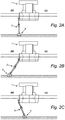
- the dredging head is provided in known manner with a visor which can be rotated between a lowered and a raised position around an axis running transversely of a dragging direction.
- the visor has a suction opening facing toward the bottom for suctioning up bottom material dislodged by a lower edge of the visor.
- the dredging head connected to the suction-blow conduit is lowered underwater and dragged in the lowered position in a dragging direction of the trailing suction hopper dredger over the bottom for dredging, wherein bottom material is dislodged.
- the dislodged bottom material is generally suctioned away with a quantity of water to a bin of the dredging vessel by the suction-blow conduit connected to a dredge pump.
- the flow through the suction-blow conduit is switched from a suctioning position to a blowing position, wherein water is pumped through the suction-blow conduit in the direction of the dredging head.
- This can for instance take place with hydraulic controls in the suction-blow conduit.
- An embodiment of the invented dredging head has the feature that the discharge device comprises two outlets which are configured such that during movement in the dragging direction the bottom material can be discharged on both lateral sides of the formed trench.
- the bottom material deposited on one or both lateral sides is preferably situated in the immediate vicinity of the formed trench. This is understood to mean a distance adjacently of the trench of a maximum of 20 times the trench width, more preferably a maximum of 15 times the trench width, still more preferably a maximum of 10 times the trench width and most preferably a maximum of 5 times the trench width.
- Another embodiment according to the invention provides a dredging head wherein the discharge device is connected for pivoting around a horizontal axis running transversely of the dragging direction to the connecting part or the suction-blow conduit.
- This embodiment allows adjustment of the angular position of the discharge device, in particular the angular position of the at least one outlet of the discharge device, relative to the horizontal plane. It hereby becomes possible to determine the distance adjacently of the trench at which on average the excavated bottom material comes to lie during forming of the trench. It is also possible to connect the discharge device for pivoting around a horizontal axis running parallel to the dragging direction to the connecting part or the suction-blow conduit.
- the discharge device is attached, preferably rigidly, to the visor or forms a part of the visor.
- the angular position of the discharge device can hereby be adjusted together with the angular position of the visor.
- a further embodiment of the invention provides a dredging head wherein at least one of the connecting part, the visor and the discharge device is connected for pivoting around a vertical axis to the suction-blow conduit or the connecting part.
- a connection allows at least one of the connecting part, the visor and the discharge device to rotate in a horizontal plane during forming of the trench. This enhances the accuracy of the route being followed.
- Under the influence of current and waves a dredging vessel will generally follow a route which varies to some extent from a desired route. Because the dredging head is connected via the suction-blow conduit to the dredging vessel, the route followed by the dredging head depends on the route of the dredging vessel.
- the present embodiment allows, within limits, the route of the dredging head to be made independent of the route of the dredging vessel.
- the actuators with which at least one of the connecting part, the visor and the discharge device can be pivoted around a vertical and/or a horizontal axis preferably comprise hydraulic cylinders, piston rods of which engage on a wall part of the respective component for controlling, and the cylinder housing of which engages on a fixed wall part, for instance of the suction-blow conduit.
- the wall part can be moved by extending or, conversely, retracting the movable cylinder rod.
- the connecting part for instance can thus be rotated in a horizontal plane by retracting a piston rod arranged on port side on an upper wall part of the connecting part (as seen in upstream direction) so that the dredging head is moved more to port side. It is for instance also possible to carry the discharge device to a raised position by retracting a piston rod arranged on an upper wall part of the discharge device, or to move it in the direction of a lowered position by extending the piston rod.
- the route followed by the dredging head can further be set more precisely by providing a dredging head in an embodiment which further comprises a steering fin which extends in the dragging direction and which is configured to penetrate into the underwater bottom.
- a steering fin produces a reaction force in the underwater bottom with which the dredging head can be steered more effectively in a desired direction.
- a practical embodiment of the dredging head is characterized in that an underside of the connecting part comprises one or more steering fins.
- Such steering fins can for instance comprise a number of plates welded to the underside of the connecting part, preferably parallel to each other.
- Yet another embodiment according to the invention provides a dredging head wherein the lower edge of the visor comprises at least two series of cutting tools for penetrating into the bottom, wherein each series extends along a line transversely of the dragging direction, and wherein the cutting tools of a first series penetrate less deeply into the bottom than the cutting tools of a second series located downstream relative to the first series.
- a relatively deep trench to be formed in the underwater bottom in one pass of the dredging head, wherein the first series of cutting tools forms a trench to a first depth, which first depth is further deepened to a greater second depth with the second series of cutting tools.
- the geometry of the cutting tools can for instance be adapted here to the ground condition.
- the depth to which the first and second series of cutting tools can be inserted can be selected within broad limits. Suitable excavating depths for each series depend on, among other factors, the ground condition and can amount for instance to between 10-80 cm, more preferably to between 20-70 cm and most preferably to between 30-50 cm.
- the connecting part comprises two lateral walls and the walls are provided with laterally extending blades.
- These blades preferably have a concave front surface, wherein the front surface faces in an upstream direction during forming of the trench.
- a side edge of the blades preferably runs obliquely upward, this such that the blades widen in upward direction.
- a trench is hereby obtained which widens a little from the bottom upwards. Such an upward widening trench section allows the suction-blow conduit to be placed at an angle in the trench, whereby the dredging head can better follow a desired route.
- the discharge device can in principle take any form as long as it comprises an inlet for the bottom material connecting to the opening of the visor, and one or more outlets.
- a suitable embodiment comprises a box-like holder body, an end surface of which connects to the opening of the visor.
- the holder body On another side the holder body comprises one or more spout-like outlets which are oriented in lateral direction relative to the formed trench (or a vertical central plane of the dredging head).
- the dredging head is particularly suitable for forming a relatively narrow trench.
- An embodiment of the dredging head is characterized for this purpose in that it has a width transversely of the dragging direction of a maximum of 3 m, more preferably a maximum of 2.5 m, still more preferably a maximum of 2 m and most preferably a maximum of 1 m.
- the invention likewise relates to a dredging device for forming a trench in an underwater bottom, comprising a dredging vessel configured for movement in a dragging direction and a dredging head according to the invention connected to a suction-blow conduit of the dredging vessel.
- An embodiment of the dredging device comprises control means for controlling the dredging head, in particular for controlling the position of the dredging head.
- the dredging head or components of the dredging head are for this purpose preferably connected for pivoting around a horizontal and/or vertical axis running transversely of the dragging direction to a fixed component, for instance the suction-blow conduit.
- the pivoting connections are controlled in embodiments by an actuator, preferably a hydraulic cylinder, wherein the control means are configured to control the actuators.
- Such control means are per se known and are for instance used in the known trailing suction hopper dredger to adjust the angular position of the visor relative to the horizontal plane.
- a method for forming a trench in an underwater bottom with the dredging device is connected here to the suction-blow conduit of the dredging vessel, a dredge pump of the dredging vessel carries water through the suction-blow conduit in the direction of the dredging head and the dredging head is moved over the underwater bottom in a dragging direction along an intended route of the trench.
- An opening of the visor of the dredging head facing toward the bottom takes up bottom material dislodged by a lower edge of the visor and, via the inlet of the discharge device connecting to the opening of the visor, discharges this material to the at least one outlet of the discharge device which is configured such that during movement in the dragging direction the bottom material is discharged to at least one lateral side of the formed trench.
- the method according to the invention is particularly suitable for forming a trench in a cohesive underwater bottom, preferably an underwater bottom comprising clay.
- Figure 1 shows a dredging vessel 1 which is provided with a motor, not shown in the drawing, for driving a propeller 2 via a propeller shaft for the purpose of propelling dredging vessel 1 in a dragging direction 7. Also present are devices, not shown in the drawings, for steering dredging vessel 1, such as a rudder and transversely placed propellers for facilitating manoeuvring.
- a dredge pump is arranged in dredging vessel 1.
- a suction-blow conduit 3 Arranged against a side wall of the dredging vessel is a suction-blow conduit 3, one end of which is connected to the dredge pump.
- the suction-blow conduit 3 comprises two members 3a and 3b which are connected to each other by means of a coupling 3c allowing some relative angular displacement.
- the connection between upper member 3a of suction-blow conduit 3 and the vessel also allows angular displacement in the vertical plane and about a substantially horizontal axis 3d.
- a dredging head 6 is arranged on the free end of second member 3b of suction-blow conduit 3.
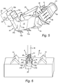
- Dredging head 6 comprises a connecting part 8 which is connectable to suction-blow conduit 3 and which in the shown embodiment comprises a fixed connecting part 8a and a movable connecting part 8b connected for pivoting around vertical shaft 9 to fixed connecting part 8a.
- Fixed connecting part 8a can be attached fixedly to suction-blow conduit 3 with flange 10.
- Dredging head 6 further comprises a visor 12 which is rotatable relative to connecting part 8 around a shaft 11 running transversely of dragging direction 7 and which has an opening 13 facing toward the bottom for taking up dislodged bottom material 14.
- a lower edge of visor 12 comprises two series of cutting devices (15a, 15b) for penetrating into the bottom.
- Cutting devices (15a, 15b) are per se known and can comprise any type of tooth.
- Each series of cutting devices (15a, 15b) extends along a line transversely of dragging direction 7.
- Cutting devices 15a of the first series moreover penetrate less deeply into the bottom than cutting devices 15b of the second series of cutting devices 15b lying upstream relative to the first series.
- the cutting devices can for instance be mounted in usual manner on a toothed beam running transversely of dragging direction 7.
- Dredging head 6 is further provided with a discharge device 16 for discharging the dislodged bottom material 14 laterally of the formed trench.
- discharge device 16 comprises a box-like body comprising two side walls (16a, 16b), an upper wall 16c and a lower wall 16d.
- Discharge device 16 connects with a first end surface 17a to an opening (not shown) in a rear wall of visor 12.
- First end surface 17a thus forms an inlet for dislodged bottom material coming from visor opening 13.
- Discharge device 16 further comprises a second end surface 17b which is located opposite first end surface 17a and which connects to two spout-like parts (18a, 18b).
- Each part (18a, 18b) is provided with an outlet (19a, 19b) along which dislodged bottom material can escape.
- Spout-like parts (18a, 18b) form a throughfeed channel for the bottom material and both extend outward from a vertical plane of symmetry 20 of dredging head 6 at an oblique angle 21 to a horizontal plane 22, see for instance figure 4 .
- outlets (19a, 19b) are configured such that during the movement of dredging head 6 in dragging direction 7 the bottom material 14 is discharged to both lateral sides of the formed trench 23 and deposited there as according to arrows (24a, 24b).
- the shown dredging head 6 can have a width of a maximum of 2 m transversely of the dragging direction 7.
- the discharge device 16 is attached fixedly to visor 12 via end surface 17a, for instance by means of a welded connection. Discharge device 16 can thus pivot, together with visor 12, around the horizontal shaft 11 running transversely of dragging direction 7.
- the angular position of visor 12 and discharge device 16 relative to the horizontal plane 22 can be adjusted by an actuator in the form of a hydraulic cylinder 25 which can be controlled from dredging vessel 1 with appropriate and per se known control means (not shown).
- movable connecting part 8b is connected for pivoting around a vertical shaft 9 to fixed connecting part 8a, which is in turn fixedly connected to lower member 3b of suction-blow conduit 3.
- the angular position of movable connecting part 8a (and so also of visor 12 and discharge device 16) relative to the vertical central plane 20 can be adjusted by a second actuator in the form of a hydraulic cylinder 26 which engages on fixed connecting part 8a at a distance from the vertical central plane 20 and can be controlled from dredging vessel 1 with appropriate and per se known control means (not shown).
- Rotation shaft 9 lies here in the vertical central plane 20.
- dredging head 6 By extending hydraulic cylinder 26 the dredging head 6 will be moved around rotation shaft 9 from port side BB to starboard side SB as according to arrow 27, see figure 3 . By subsequently retracting the rod of hydraulic cylinder 26 the dredging head 6 will be moved around rotation shaft 9 from starboard side SB to port side BB as according to arrow 28, see figure 3 .
- the control of dredging head 6 can be further improved by providing an underside of movable connecting part 8b with a number of steering fins 29 which extend in the dragging direction and which are configured to penetrate into the underwater bottom.
- dredging vessel 1 has a position more toward the port side BB relative to the desired route. In order to nevertheless move dredging head 6 forward accurately along the route it is in this case steered toward the starboard side SB. A trench 23 can in this way be excavated in accurate manner along a predetermined desired route.
- blades 30 preferably have a concave front surface 30a, wherein front surface 30a faces in an upstream direction during the forming of trench 23.
- a side edge 30b of blades 30 preferably runs obliquely upward, this such that blades 30 widen toward the top.
- a trench 23 is hereby obtained which widens a little from the bottom upward.
- Dredging head 6 is connected here to suction-blow conduit 3 of dredging vessel 1, and a dredge pump (not shown) of dredging vessel 1 carries water through suction-blow conduit 3 in the direction of dredging head 6 while dredging head 6 is moved over the underwater bottom in a dragging direction 7 along an intended route of trench 23.
- the opening 13 of visor 12 of dredging head 6 facing toward the bottom takes up bottom material dislodged by cutting devices (15a, 15b) and this material is discharged by the generated water flow via the inlet of discharge device 16 connecting to opening 13 to outlets (19a, 19b) of discharge device 16.
- the thus discharged bottom material is discharged via the outlets to the lateral sides of the formed trench 23 and deposited there.
- the formed trench 23 can if desired be filled by moving the bottom material discharged and heaped on the lateral sides into trench 23 with an implement suitable for the purpose, such as a plough, with the proviso that prior to filling thereof the formed trench 23 is provided with the object, for instance a cable or conduit.
- an implement suitable for the purpose such as a plough
Landscapes
- Engineering & Computer Science (AREA)
- Mechanical Engineering (AREA)
- Mining & Mineral Resources (AREA)
- Civil Engineering (AREA)
- General Engineering & Computer Science (AREA)
- Structural Engineering (AREA)
- Underground Or Underwater Handling Of Building Materials (AREA)
- Farming Of Fish And Shellfish (AREA)
Claims (15)
- Baggerkopf zum Bilden eines Grabens in einem Unterwasserboden, wobei der Baggerkopf ein Verbindungsteil zum Verbinden mit einer Saug-/Blasleitung eines in Schlepprichtung zu bewegenden Baggerschiffes aufweist und wobei der Baggerkopf eine Blende zum Drehen um eine horizontale Achse aufweist, die quer zur Schlepprichtung mit einer Öffnung verläuft, die zum Boden gerichtet ist, um Bodenmaterial aufzunehmen, das durch eine Unterkante der Blende gelöst wird, dadurch gekennzeichnet, dass der Baggerkopf weiterhin eine Austrageinheit für das gelöste Bodenmaterial aufweist, wobei die Austrageinheit einen Einlass für das Bodenmaterial aufweist, der mit der Öffnung der Blende verbunden ist, und mindestens einen Auslass aufweist, der so konfiguriert ist, dass das Bodenmaterial während der Bewegung in Schlepprichtung auf mindestens einer seitlichen Seite des gebildeten Grabens ausgetragen werden kann.
- Baggerkopf nach Anspruch 1, wobei die Austrageinheit zwei Auslässe aufweist, die so konfiguriert sind, dass das Bodenmaterial während der Bewegung in Schlepprichtung auf beiden seitlichen Seiten des gebildeten Grabens ausgetragen werden kann.
- Baggerkopf nach Anspruch 1 oder 2, wobei die Austrageinheit mit dem Verbindungsteil oder der Saug-/Blasleitung zum Drehen um eine horizontale Achse verbunden ist, die parallel zur Schlepprichtung verläuft.
- Baggerkopf nach einem der vorherigen Ansprüche, wobei die Austrageinheit an der Blende angebracht ist oder einen Teil der Blende bildet.
- Baggerkopf nach einem der vorherigen Ansprüche, wobei mindestens entweder das Verbindungsteil, die Blende oder die Austrageinheit mit der Saug-/Blasleitung oder dem Verbindungsteil zum Drehen um eine vertikale Achse verbunden ist.
- Baggerkopf nach Anspruch 5, wobei die mindestens eine Drehverbindung durch ein Stellglied, vorzugsweise einen Hydraulikzylinder, gesteuert wird.
- Baggerkopf nach Anspruch 5 oder 6, wobei das Verbindungsteil mit der Saug-/Blasleitung zum Drehen um eine vertikale Achse verbunden ist.
- Baggerkopf nach einem der vorherigen Ansprüche, der weiterhin eine Lenkrippe aufweist, die sich in Schlepprichtung erstreckt und so konfiguriert ist, dass sie in den Unterwasserboden eindringt.
- Baggerkopf nach Anspruch 8, wobei eine Unterseite des Verbindungsteils eine oder mehrere Lenkrippen aufweist.
- Baggerkopf nach einem der vorherigen Ansprüche, wobei die Unterkante der Blende mindestens zwei Reihen von Schneidwerkzeugen zum Eindringen in den Boden aufweist, wobei sich jede Reihe entlang einer Linie quer zur Schlepprichtung erstreckt und wobei die Schneidwerkzeuge einer ersten Reihe weniger tief in den Boden eindringen als die Schneidwerkzeuge einer zweiten Reihe, die sich im Vergleich zur ersten Reihe nachgelagert befinden.
- Baggerkopf nach einem der vorherigen Ansprüche, wobei das Verbindungsteil zwei Seitenwände aufweist und die Wände mit seitlich verlaufenden Flügeln versehen sind.
- Baggereinheit zum Bilden eines Grabens in einem Unterwasserboden, die ein Baggerschiff aufweist, das so konfiguriert ist, dass es sich in eine Schlepprichtung bewegt, sowie ein Baggerkopf nach einem der Ansprüche 1 bis 11, der mit einer Saug-/Blasleitung des Baggerschiffes verbunden ist.
- Baggereinheit nach Anspruch 12, die weiterhin Steuermittel zum Steuern des Baggerkopfes aufweist, wobei die mindestens eine Drehverbindung des Baggerkopfes von einem Stellglied gesteuert wird, und die Steuermittel so konfiguriert sind, dass sie das Stellglied steuern.
- Verfahren zum Bilden eines Grabens in einem Unterwasserboden mit einer Baggereinheit nach einem der Ansprüche 12 bis 13, wobei der Baggerkopf mit der Saug-/Blasleitung des Baggerschiffes verbunden ist, eine Baggerpumpe des Baggerschiffes Wasser durch die Saug-/Blasleitung in Richtung des Baggerkopfes fördert und der Baggerkopf in Schlepprichtung entlang eines geplanten Weges des Grabens über den Unterwasserboden bewegt wird, dadurch gekennzeichnet, dass eine Öffnung der Blende des Baggerkopfes, die zum Boden gerichtet ist, von einer Unterkante der Blende gelöstes Bodenmaterial aufnimmt und über einen Einlass der Austrageinheit, die mit der Öffnung der Blende verbunden ist, dieses Material zu mindestens einem Auslass der Austrageinheit austrägt, die so konfiguriert ist, dass das Bodenmaterial während der Bewegung in Schlepprichtung zu mindestens einer seitlichen Seite des gebildeten Grabens ausgetragen wird.
- Verfahren nach Anspruch 14, wobei der gebildete Graben durch Bewegen des ausgetragenen Bodenmaterials gefüllt und auf mindestens einer seitlichen Seite mit einem geeigneten Gerät, wie beispielsweise einem Pflug, in den Graben gehäuft wird, und wobei der gebildete Graben vor dem Befüllen mit einem Objekt, wie beispielsweise einem Kabel oder einer Leitung, versehen ist.
Priority Applications (1)
| Application Number | Priority Date | Filing Date | Title |
|---|---|---|---|
| PL17154845T PL3205778T3 (pl) | 2016-02-05 | 2017-02-06 | Głowica pogłębiająca oraz powiązany sposób do tworzenia rowu w dnie podwodnym |
Applications Claiming Priority (1)
| Application Number | Priority Date | Filing Date | Title |
|---|---|---|---|
| BE2016/5092A BE1024130B1 (nl) | 2016-02-05 | 2016-02-05 | Baggerkop en bijbehorende werkwijze voor het vormen van een geul in een onderwaterbodem |
Publications (2)
| Publication Number | Publication Date |
|---|---|
| EP3205778A1 EP3205778A1 (de) | 2017-08-16 |
| EP3205778B1 true EP3205778B1 (de) | 2018-12-12 |
Family
ID=55587976
Family Applications (1)
| Application Number | Title | Priority Date | Filing Date |
|---|---|---|---|
| EP17154845.6A Active EP3205778B1 (de) | 2016-02-05 | 2017-02-06 | Baggerkopf und zugehöriges verfahren zur formung eines grabens in einem unterwasserboden |
Country Status (5)
| Country | Link |
|---|---|
| EP (1) | EP3205778B1 (de) |
| BE (1) | BE1024130B1 (de) |
| DK (1) | DK3205778T3 (de) |
| ES (1) | ES2711201T3 (de) |
| PL (1) | PL3205778T3 (de) |
Families Citing this family (5)
| Publication number | Priority date | Publication date | Assignee | Title |
|---|---|---|---|---|
| CN107740457A (zh) * | 2017-10-30 | 2018-02-27 | 中交疏浚技术装备国家工程研究中心有限公司 | 带滚刀的环保疏浚装置 |
| CN108374445B (zh) * | 2018-05-15 | 2021-03-05 | 河南黄河勘测规划设计研究院有限公司 | 一种多功能水利施工清淤疏通装置 |
| CN108797686B (zh) * | 2018-06-27 | 2020-10-30 | 安徽佳明环保科技股份有限公司 | 一种用于泥沙耙吸船的耙头装置 |
| CN110886232B (zh) * | 2019-12-17 | 2021-02-02 | 成都市路桥工程股份有限公司 | 一种桥梁施工设备 |
| CN114452888B (zh) * | 2022-03-01 | 2024-04-05 | 平顶山市畜牧技术推广站(平顶山市地方畜禽品种资源保护中心) | 一种用于牛羊饲养的自动喂料装置及其工作方法 |
Family Cites Families (4)
| Publication number | Priority date | Publication date | Assignee | Title |
|---|---|---|---|---|
| IT1138764B (it) * | 1981-05-04 | 1986-09-17 | Snam Progetti | Dispositivo per interramento o dissotterramento di condotte subacquee |
| WO2001092650A1 (en) | 2000-05-31 | 2001-12-06 | Soil Machine Dynamics Limited | Underwater earth moving machine |
| BE1019788A4 (nl) * | 2011-02-02 | 2012-12-04 | Baggerwerken Decloedt & Zn N V | Zuigkop voor een baggerschip en werkwijze voor het baggeren met behulp van deze zuigkop. |
| BE1020439A4 (nl) * | 2012-05-25 | 2013-10-01 | Baggerwerken Decloedt En Zoon | Zuigkop van een sleephopperzuiger en werkwijze voor het baggeren met behulp van deze zuigkop. |
-
2016
- 2016-02-05 BE BE2016/5092A patent/BE1024130B1/nl not_active IP Right Cessation
-
2017
- 2017-02-06 EP EP17154845.6A patent/EP3205778B1/de active Active
- 2017-02-06 ES ES17154845T patent/ES2711201T3/es active Active
- 2017-02-06 DK DK17154845.6T patent/DK3205778T3/en active
- 2017-02-06 PL PL17154845T patent/PL3205778T3/pl unknown
Non-Patent Citations (1)
| Title |
|---|
| None * |
Also Published As
| Publication number | Publication date |
|---|---|
| EP3205778A1 (de) | 2017-08-16 |
| ES2711201T3 (es) | 2019-04-30 |
| PL3205778T3 (pl) | 2019-06-28 |
| BE1024130B1 (nl) | 2017-11-20 |
| DK3205778T3 (en) | 2019-03-18 |
| BE1024130A1 (nl) | 2017-11-17 |
Similar Documents
| Publication | Publication Date | Title |
|---|---|---|
| EP3205778B1 (de) | Baggerkopf und zugehöriges verfahren zur formung eines grabens in einem unterwasserboden | |
| NL2009108C2 (en) | Vessel for forming a trench in a water bottom. | |
| EP2729629B1 (de) | Saugkopf und laderaumsaugbagger | |
| EP2582885B1 (de) | Verfahren und vorrichtung für eine meeresboden-hilfsabsaugung | |
| EP0029469B1 (de) | Baggerverfahren und Baggerausrüstung | |
| JP2022060519A (ja) | 海底にトレンチを形成する方法及び装置 | |
| EP3397816B1 (de) | Unterwasserpflug und pflügen | |
| US4395158A (en) | Method and apparatus for entrenching an enlongated under-water structure | |
| EP3271517B1 (de) | Baggervorrichtung und druckverfahren | |
| KR20110126600A (ko) | 수중에서 지반을 굴착하는 굴착기 및 지반 굴착 방법 | |
| EP3260605B1 (de) | Vorrichtung und verfahren zur abscheidung von material auf einem unterwasserboden | |
| JPS595759B2 (ja) | 自由に懸垂した吸込パイプによつて海底沈積物を採掘する方法及び装置 | |
| NL2020061B1 (en) | Device and associated method for clearing boulders and other objects from an underwater bottom | |
| NL2009062C2 (en) | Vessel for forming a trench in a water bottom. | |
| US20240401305A1 (en) | Subsea Blower Device | |
| EP3259409B1 (de) | Saugkopf für ein baggerschiff und verfahren zum baggern mit verwendung des besagten saugkopfs | |
| CN121205259A (zh) | 一种耙吸挖泥船目标参数自动挖泥控制方法 | |
| NL8105915A (nl) | Werkwijze en inrichting ter vermindering van kosten en milieubeinvloeding van baggeren. |
Legal Events
| Date | Code | Title | Description |
|---|---|---|---|
| PUAI | Public reference made under article 153(3) epc to a published international application that has entered the european phase |
Free format text: ORIGINAL CODE: 0009012 |
|
| STAA | Information on the status of an ep patent application or granted ep patent |
Free format text: STATUS: THE APPLICATION HAS BEEN PUBLISHED |
|
| AK | Designated contracting states |
Kind code of ref document: A1 Designated state(s): AL AT BE BG CH CY CZ DE DK EE ES FI FR GB GR HR HU IE IS IT LI LT LU LV MC MK MT NL NO PL PT RO RS SE SI SK SM TR |
|
| AX | Request for extension of the european patent |
Extension state: BA ME |
|
| STAA | Information on the status of an ep patent application or granted ep patent |
Free format text: STATUS: REQUEST FOR EXAMINATION WAS MADE |
|
| 17P | Request for examination filed |
Effective date: 20180212 |
|
| RBV | Designated contracting states (corrected) |
Designated state(s): AL AT BE BG CH CY CZ DE DK EE ES FI FR GB GR HR HU IE IS IT LI LT LU LV MC MK MT NL NO PL PT RO RS SE SI SK SM TR |
|
| GRAP | Despatch of communication of intention to grant a patent |
Free format text: ORIGINAL CODE: EPIDOSNIGR1 |
|
| STAA | Information on the status of an ep patent application or granted ep patent |
Free format text: STATUS: GRANT OF PATENT IS INTENDED |
|
| INTG | Intention to grant announced |
Effective date: 20180621 |
|
| GRAS | Grant fee paid |
Free format text: ORIGINAL CODE: EPIDOSNIGR3 |
|
| GRAA | (expected) grant |
Free format text: ORIGINAL CODE: 0009210 |
|
| STAA | Information on the status of an ep patent application or granted ep patent |
Free format text: STATUS: THE PATENT HAS BEEN GRANTED |
|
| AK | Designated contracting states |
Kind code of ref document: B1 Designated state(s): AL AT BE BG CH CY CZ DE DK EE ES FI FR GB GR HR HU IE IS IT LI LT LU LV MC MK MT NL NO PL PT RO RS SE SI SK SM TR |
|
| REG | Reference to a national code |
Ref country code: GB Ref legal event code: FG4D |
|
| REG | Reference to a national code |
Ref country code: CH Ref legal event code: EP |
|
| REG | Reference to a national code |
Ref country code: AT Ref legal event code: REF Ref document number: 1076141 Country of ref document: AT Kind code of ref document: T Effective date: 20181215 |
|
| REG | Reference to a national code |
Ref country code: IE Ref legal event code: FG4D |
|
| REG | Reference to a national code |
Ref country code: DE Ref legal event code: R096 Ref document number: 602017001238 Country of ref document: DE |
|
| REG | Reference to a national code |
Ref country code: DK Ref legal event code: T3 Effective date: 20190311 |
|
| REG | Reference to a national code |
Ref country code: NL Ref legal event code: FP |
|
| REG | Reference to a national code |
Ref country code: LT Ref legal event code: MG4D |
|
| PG25 | Lapsed in a contracting state [announced via postgrant information from national office to epo] |
Ref country code: LV Free format text: LAPSE BECAUSE OF FAILURE TO SUBMIT A TRANSLATION OF THE DESCRIPTION OR TO PAY THE FEE WITHIN THE PRESCRIBED TIME-LIMIT Effective date: 20181212 Ref country code: HR Free format text: LAPSE BECAUSE OF FAILURE TO SUBMIT A TRANSLATION OF THE DESCRIPTION OR TO PAY THE FEE WITHIN THE PRESCRIBED TIME-LIMIT Effective date: 20181212 Ref country code: BG Free format text: LAPSE BECAUSE OF FAILURE TO SUBMIT A TRANSLATION OF THE DESCRIPTION OR TO PAY THE FEE WITHIN THE PRESCRIBED TIME-LIMIT Effective date: 20190312 Ref country code: LT Free format text: LAPSE BECAUSE OF FAILURE TO SUBMIT A TRANSLATION OF THE DESCRIPTION OR TO PAY THE FEE WITHIN THE PRESCRIBED TIME-LIMIT Effective date: 20181212 Ref country code: FI Free format text: LAPSE BECAUSE OF FAILURE TO SUBMIT A TRANSLATION OF THE DESCRIPTION OR TO PAY THE FEE WITHIN THE PRESCRIBED TIME-LIMIT Effective date: 20181212 Ref country code: NO Free format text: LAPSE BECAUSE OF FAILURE TO SUBMIT A TRANSLATION OF THE DESCRIPTION OR TO PAY THE FEE WITHIN THE PRESCRIBED TIME-LIMIT Effective date: 20190312 |
|
| REG | Reference to a national code |
Ref country code: ES Ref legal event code: FG2A Ref document number: 2711201 Country of ref document: ES Kind code of ref document: T3 Effective date: 20190430 |
|
| REG | Reference to a national code |
Ref country code: AT Ref legal event code: MK05 Ref document number: 1076141 Country of ref document: AT Kind code of ref document: T Effective date: 20181212 |
|
| PG25 | Lapsed in a contracting state [announced via postgrant information from national office to epo] |
Ref country code: SE Free format text: LAPSE BECAUSE OF FAILURE TO SUBMIT A TRANSLATION OF THE DESCRIPTION OR TO PAY THE FEE WITHIN THE PRESCRIBED TIME-LIMIT Effective date: 20181212 Ref country code: RS Free format text: LAPSE BECAUSE OF FAILURE TO SUBMIT A TRANSLATION OF THE DESCRIPTION OR TO PAY THE FEE WITHIN THE PRESCRIBED TIME-LIMIT Effective date: 20181212 Ref country code: GR Free format text: LAPSE BECAUSE OF FAILURE TO SUBMIT A TRANSLATION OF THE DESCRIPTION OR TO PAY THE FEE WITHIN THE PRESCRIBED TIME-LIMIT Effective date: 20190313 Ref country code: AL Free format text: LAPSE BECAUSE OF FAILURE TO SUBMIT A TRANSLATION OF THE DESCRIPTION OR TO PAY THE FEE WITHIN THE PRESCRIBED TIME-LIMIT Effective date: 20181212 |
|
| PG25 | Lapsed in a contracting state [announced via postgrant information from national office to epo] |
Ref country code: CZ Free format text: LAPSE BECAUSE OF FAILURE TO SUBMIT A TRANSLATION OF THE DESCRIPTION OR TO PAY THE FEE WITHIN THE PRESCRIBED TIME-LIMIT Effective date: 20181212 Ref country code: IT Free format text: LAPSE BECAUSE OF FAILURE TO SUBMIT A TRANSLATION OF THE DESCRIPTION OR TO PAY THE FEE WITHIN THE PRESCRIBED TIME-LIMIT Effective date: 20181212 Ref country code: PT Free format text: LAPSE BECAUSE OF FAILURE TO SUBMIT A TRANSLATION OF THE DESCRIPTION OR TO PAY THE FEE WITHIN THE PRESCRIBED TIME-LIMIT Effective date: 20190412 |
|
| PG25 | Lapsed in a contracting state [announced via postgrant information from national office to epo] |
Ref country code: SK Free format text: LAPSE BECAUSE OF FAILURE TO SUBMIT A TRANSLATION OF THE DESCRIPTION OR TO PAY THE FEE WITHIN THE PRESCRIBED TIME-LIMIT Effective date: 20181212 Ref country code: IS Free format text: LAPSE BECAUSE OF FAILURE TO SUBMIT A TRANSLATION OF THE DESCRIPTION OR TO PAY THE FEE WITHIN THE PRESCRIBED TIME-LIMIT Effective date: 20190412 Ref country code: RO Free format text: LAPSE BECAUSE OF FAILURE TO SUBMIT A TRANSLATION OF THE DESCRIPTION OR TO PAY THE FEE WITHIN THE PRESCRIBED TIME-LIMIT Effective date: 20181212 Ref country code: EE Free format text: LAPSE BECAUSE OF FAILURE TO SUBMIT A TRANSLATION OF THE DESCRIPTION OR TO PAY THE FEE WITHIN THE PRESCRIBED TIME-LIMIT Effective date: 20181212 Ref country code: SM Free format text: LAPSE BECAUSE OF FAILURE TO SUBMIT A TRANSLATION OF THE DESCRIPTION OR TO PAY THE FEE WITHIN THE PRESCRIBED TIME-LIMIT Effective date: 20181212 |
|
| REG | Reference to a national code |
Ref country code: DE Ref legal event code: R097 Ref document number: 602017001238 Country of ref document: DE |
|
| PLBE | No opposition filed within time limit |
Free format text: ORIGINAL CODE: 0009261 |
|
| STAA | Information on the status of an ep patent application or granted ep patent |
Free format text: STATUS: NO OPPOSITION FILED WITHIN TIME LIMIT |
|
| PG25 | Lapsed in a contracting state [announced via postgrant information from national office to epo] |
Ref country code: SI Free format text: LAPSE BECAUSE OF FAILURE TO SUBMIT A TRANSLATION OF THE DESCRIPTION OR TO PAY THE FEE WITHIN THE PRESCRIBED TIME-LIMIT Effective date: 20181212 Ref country code: AT Free format text: LAPSE BECAUSE OF FAILURE TO SUBMIT A TRANSLATION OF THE DESCRIPTION OR TO PAY THE FEE WITHIN THE PRESCRIBED TIME-LIMIT Effective date: 20181212 Ref country code: MC Free format text: LAPSE BECAUSE OF FAILURE TO SUBMIT A TRANSLATION OF THE DESCRIPTION OR TO PAY THE FEE WITHIN THE PRESCRIBED TIME-LIMIT Effective date: 20181212 Ref country code: LU Free format text: LAPSE BECAUSE OF NON-PAYMENT OF DUE FEES Effective date: 20190206 |
|
| 26N | No opposition filed |
Effective date: 20190913 |
|
| REG | Reference to a national code |
Ref country code: IE Ref legal event code: MM4A |
|
| PG25 | Lapsed in a contracting state [announced via postgrant information from national office to epo] |
Ref country code: IE Free format text: LAPSE BECAUSE OF NON-PAYMENT OF DUE FEES Effective date: 20190206 |
|
| PG25 | Lapsed in a contracting state [announced via postgrant information from national office to epo] |
Ref country code: TR Free format text: LAPSE BECAUSE OF FAILURE TO SUBMIT A TRANSLATION OF THE DESCRIPTION OR TO PAY THE FEE WITHIN THE PRESCRIBED TIME-LIMIT Effective date: 20181212 |
|
| PG25 | Lapsed in a contracting state [announced via postgrant information from national office to epo] |
Ref country code: MT Free format text: LAPSE BECAUSE OF NON-PAYMENT OF DUE FEES Effective date: 20190206 |
|
| REG | Reference to a national code |
Ref country code: CH Ref legal event code: PL |
|
| PG25 | Lapsed in a contracting state [announced via postgrant information from national office to epo] |
Ref country code: LI Free format text: LAPSE BECAUSE OF NON-PAYMENT OF DUE FEES Effective date: 20200229 Ref country code: CH Free format text: LAPSE BECAUSE OF NON-PAYMENT OF DUE FEES Effective date: 20200229 |
|
| PG25 | Lapsed in a contracting state [announced via postgrant information from national office to epo] |
Ref country code: CY Free format text: LAPSE BECAUSE OF FAILURE TO SUBMIT A TRANSLATION OF THE DESCRIPTION OR TO PAY THE FEE WITHIN THE PRESCRIBED TIME-LIMIT Effective date: 20181212 |
|
| PG25 | Lapsed in a contracting state [announced via postgrant information from national office to epo] |
Ref country code: HU Free format text: LAPSE BECAUSE OF FAILURE TO SUBMIT A TRANSLATION OF THE DESCRIPTION OR TO PAY THE FEE WITHIN THE PRESCRIBED TIME-LIMIT; INVALID AB INITIO Effective date: 20170206 |
|
| PG25 | Lapsed in a contracting state [announced via postgrant information from national office to epo] |
Ref country code: MK Free format text: LAPSE BECAUSE OF FAILURE TO SUBMIT A TRANSLATION OF THE DESCRIPTION OR TO PAY THE FEE WITHIN THE PRESCRIBED TIME-LIMIT Effective date: 20181212 |
|
| P01 | Opt-out of the competence of the unified patent court (upc) registered |
Effective date: 20230526 |
|
| PGFP | Annual fee paid to national office [announced via postgrant information from national office to epo] |
Ref country code: ES Payment date: 20250512 Year of fee payment: 9 |
|
| PGFP | Annual fee paid to national office [announced via postgrant information from national office to epo] |
Ref country code: DK Payment date: 20251223 Year of fee payment: 10 |
|
| PGFP | Annual fee paid to national office [announced via postgrant information from national office to epo] |
Ref country code: NL Payment date: 20260205 Year of fee payment: 10 |
|
| PGFP | Annual fee paid to national office [announced via postgrant information from national office to epo] |
Ref country code: GB Payment date: 20260213 Year of fee payment: 10 |
|
| PGFP | Annual fee paid to national office [announced via postgrant information from national office to epo] |
Ref country code: DE Payment date: 20260129 Year of fee payment: 10 |
|
| PGFP | Annual fee paid to national office [announced via postgrant information from national office to epo] |
Ref country code: BE Payment date: 20260204 Year of fee payment: 10 |
|
| PGFP | Annual fee paid to national office [announced via postgrant information from national office to epo] |
Ref country code: FR Payment date: 20260213 Year of fee payment: 10 |
|
| PGFP | Annual fee paid to national office [announced via postgrant information from national office to epo] |
Ref country code: PL Payment date: 20260108 Year of fee payment: 10 |