EP3205809A1 - Rollladen mit drebaren leisten - Google Patents
Rollladen mit drebaren leisten Download PDFInfo
- Publication number
- EP3205809A1 EP3205809A1 EP16425010.2A EP16425010A EP3205809A1 EP 3205809 A1 EP3205809 A1 EP 3205809A1 EP 16425010 A EP16425010 A EP 16425010A EP 3205809 A1 EP3205809 A1 EP 3205809A1
- Authority
- EP
- European Patent Office
- Prior art keywords
- slat
- slats
- active
- roll
- slider
- Prior art date
- Legal status (The legal status is an assumption and is not a legal conclusion. Google has not performed a legal analysis and makes no representation as to the accuracy of the status listed.)
- Withdrawn
Links
- 230000033001 locomotion Effects 0.000 claims abstract description 30
- 230000007704 transition Effects 0.000 claims abstract description 4
- 230000000295 complement effect Effects 0.000 claims description 4
- 230000009467 reduction Effects 0.000 claims description 4
- 238000013459 approach Methods 0.000 claims description 2
- 230000005540 biological transmission Effects 0.000 claims description 2
- 230000003247 decreasing effect Effects 0.000 claims 1
- 230000008878 coupling Effects 0.000 description 4
- 238000010168 coupling process Methods 0.000 description 4
- 238000005859 coupling reaction Methods 0.000 description 4
- 230000000670 limiting effect Effects 0.000 description 3
- 241000238631 Hexapoda Species 0.000 description 2
- 238000013519 translation Methods 0.000 description 2
- 238000004804 winding Methods 0.000 description 2
- 241001465754 Metazoa Species 0.000 description 1
- 230000007423 decrease Effects 0.000 description 1
- 230000001627 detrimental effect Effects 0.000 description 1
- 230000000694 effects Effects 0.000 description 1
- 230000013011 mating Effects 0.000 description 1
- 238000000034 method Methods 0.000 description 1
- 238000012986 modification Methods 0.000 description 1
- 230000004048 modification Effects 0.000 description 1
- 230000010355 oscillation Effects 0.000 description 1
- 230000001681 protective effect Effects 0.000 description 1
- 230000000284 resting effect Effects 0.000 description 1
- 238000012546 transfer Methods 0.000 description 1
Images


Classifications
-
- E—FIXED CONSTRUCTIONS
- E06—DOORS, WINDOWS, SHUTTERS, OR ROLLER BLINDS IN GENERAL; LADDERS
- E06B—FIXED OR MOVABLE CLOSURES FOR OPENINGS IN BUILDINGS, VEHICLES, FENCES OR LIKE ENCLOSURES IN GENERAL, e.g. DOORS, WINDOWS, BLINDS, GATES
- E06B9/00—Screening or protective devices for wall or similar openings, with or without operating or securing mechanisms; Closures of similar construction
- E06B9/24—Screens or other constructions affording protection against light, especially against sunshine; Similar screens for privacy or appearance; Slat blinds
- E06B9/26—Lamellar or like blinds, e.g. venetian blinds
- E06B9/28—Lamellar or like blinds, e.g. venetian blinds with horizontal lamellae, e.g. non-liftable
- E06B9/34—Lamellar or like blinds, e.g. venetian blinds with horizontal lamellae, e.g. non-liftable roller-type; Roller shutters with adjustable lamellae
Definitions
- the present invention relates to a roll-up shutter.
- roll-up shutters also known as blinds
- blinds are constructive solutions arranged so as to close windows (or other openings) of homes or buildings in general.
- roll-up shutters comprise a plurality of mutually parallel slats arranged horizontally: in the configuration for use, the slats are arranged side by side and substantially in contact in pairs, so as to cover progressively the window (the opening) and achieve its desired closure. In this configuration, the shutter thus hinders the passage of light, atmospheric agents, insects and other animals, and also of people.
- the slats are mutually coupled so as to be able to actuate their winding around a roller, which is usually arranged above the window, in a compartment provided for this purpose in the wall.
- the slats when they are wound around the roller, the slats define an inactive configuration, in which they do not obstruct the window in any way.
- the roller can be moved manually (by using for example a belt that is associated with it and can be actuated directly by the user) or in an automated manner, for example by means of an electric motor.
- the aim of the present invention is to solve the problems described above, by providing a roll-up shutter that allows to vary the orientation of at least some of its slats.
- an object of the invention is to provide a roll-up shutter that allows extensive possibilities of adjustment of the orientation of at least some of its slats.
- Another object of the invention is to provide a roll-up shutter that is versatile and can be used easily to close windows or doors of any type, even in case of imperfections of the threshold and/or as a replacement of existing shutters.
- Another object of the invention is to provide a roll-up shutter that ensures high reliability of operation and is capable of withstanding break-in attempts.
- Another object of the invention is to devise a roll-up shutter that adopts a technical and structural architecture that is alternative to those of known types of shutter.
- Another object of the invention is to provide a roll-up shutter that can be obtained easily starting from commonly commercially available elements and materials.
- Another object of the invention is to provide a roll-up shutter that has low costs and is safe in application.
- a roll-up shutter which can be installed at openings such as windows, doors or the like, comprising an apparatus for moving a plurality of slats which are arranged in series, are parallel and are mutually coupled even indirectly, for their transition from at least a first inactive configuration, in which said slats are spaced from the opening, to at least a second active configuration, in which said slats are distributed so as to be mutually side by side substantially along the entire extension of the opening, and vice versa, characterized in that said apparatus comprises at least one slider assembly, which can move integrally with said plurality of said slats during their movement between said configurations and meshes with at least one said active slat, which can rotate about a longitudinal axis thereof, said at least one slider assembly being movable by a respective actuation cam, while said plurality of said slats is kept in said active configuration, for the consequent rotation of said at least one active
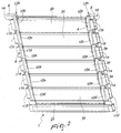
- the reference numeral 1 generally designates a roll-up shutter, which can be installed at openings A such as windows, doors or the like.
- the shutter 1 therefore comprises a movement apparatus 2 for moving a plurality of slats 3a, 3b, 3c, 3d, which are arranged in series and are parallel and mutually coupled (even indirectly).
- the apparatus 2 allows to move the slats 3a, 3b, 3c, 3d to cause their transition from at least a first inactive configuration to a second active configuration and vice versa.
- the slats 3a, 3b, 3c, 3d are spaced from the opening A, so as to not obstruct it and allow the free passage of air, light, atmospheric agents (or even insects and people).
- the opening A can still be closed by a window, a door or others.
- the slats 3a, 3b, 3c, 3d can be for example accommodated (and rolled up, as will become apparent) in a compartment B, which is provided in the wall C in which the opening A is provided and lies above the latter.
- compartment B can also accommodate almost all of the elements that compose the movement apparatus 2.
- the slats 3a, 3b, 3c, 3d are distributed so as to be mutually side by side substantially along the entire extension of the opening.
- the apparatus 2 comprises a slider assembly 4, which moves integrally with the plurality of slats 3a, 3b, 3c, 3d during their movement between the configurations mentioned above.
- the slider assembly 4 meshes with at least one active slat 3a, which can rotate about a longitudinal axis D thereof (illustrated for the sake of simplicity only in Figure 14 , which indeed shows such active slat 3a).
- the slider assembly 4 can be moved by an actuation cam 5, while the plurality of slats 3a, 3b, 3c, 3d is kept in the active configuration: indeed by way of the above cited meshing, the motion of the slider assembly 4 actuated by the cam 5 causes the consequent rotation of the active slat 3a around such longitudinal axis D.
- the rotation of the active slat 3a allows a variation of the orientation thereof and the possibility to allow light to filter through partially (and/or allow the passage of air) though keeping as a whole the slats 3a, 3b, 3c, 3d in the active configuration and therefore distributed along the entire extension of the opening A or in any case of a significant part thereof.
- the slider assembly 4 has at least one rack 7, which meshes with a respective pinion 8 that is integral with the corresponding active slat 3a (for example, Figures 9 and 14 ).
- the slider assembly 4 has more than one rack 7, each of which meshes with a respective pinion 8, which is associated with a corresponding active slat 3a.
- the roll-up shutter 1 comprises three active slats 3a, each therefore provided with the possibility to rotate, actuated by the slider assembly 4 by way of the meshing between respective racks 7 and corresponding pinions 8.
- the number of active slats 3a which can rotate about the respective longitudinal axis D, may be any according to the specific requirements and the dimensions of the opening A.
- the active slats 3a are preferably, but not exclusively, arranged consecutively in series; as will become apparent in the pages that follow, different slats 3b, 3c, 3d having other functions are further arranged ahead or after them.
- the slider assembly 4 comprises a pusher pin 9, which engages automatically the cam 5 when the plurality of slats 3a, 3b, 3c, 3d-reaches the active configuration (extends so as to cover the opening A completely or almost completely).
- each slat 3a, 3b, 3c, 3d comprises a lamina that has a rectangular contour and is associated with at least one head block that comprises at least one shoulder 10a, 10b, 10c, 10d (the letters in the reference numerals given here and hereinafter correspond to the ones used for the various slats 3a, 3b, 3c, 3d).
- Each shoulder 10a, 10b, 10c, 10d is pivoted to the shoulder 10a, 10b, 10c, 10d of the contiguous head block and faces directly and is proximate to an end of the respective slat 3a, 3b, 3c, 3d (as can be deduced clearly for example from Figures 11, 12 , 13, 14 and 15 ).
- each head block comprises at least one respective slider 11a, 11b, 11c, 11d, which is pivoted to the slider 11a, 11b, 11c, 11d of the contiguous head block and can be inserted in a corresponding vertical track E ( Figure 8 ).
- the track E can be provided around the opening A (along one or both sides) so as to obtain the guided movement of the plurality of slats 3a, 3b, 3c, 3d between the inactive configuration and the active configuration.
- it is the track E that imposes the trajectory to the slats 3a, 3b, 3c, 3d when they are moved so as to make them obstruct the opening A when they are subsequently moved away from it.
- tracks E allow vertical translation but prevent any other movement of the sliders 11 a, 11b, 11c, 11d.
- each slat 3a, 3b, 3c, 3d is associated with a single head block, with the respective slider 11 a, 11b, 11c, 11d inserted in a corresponding (single) track E, is not excluded and is in any case within the protective scope claimed herein, in the preferred embodiment (and in the accompanying figures) each slat 3a, 3b, 3c, 3d is associated with two respective head blocks.
- the head blocks of each slat 3a, 3b, 3c, 3d are substantially mirror-symmetrical and face each other and are proximate, with their corresponding shoulders 10a, 10b, 10c, 10d, to corresponding ends of the lamina.
- the structure of the shutter 1 is substantially symmetrical (also with respect to the components of the movement apparatus 2 that will be introduced in the pages that follow).
- the slider assembly 4 comprises a plurality of slider elements 12a, 12b, 12c, which in turn are comprised within respective head blocks and are interposed between corresponding sliders 11a, 11b, 11c and corresponding shoulders 10a, 10b, 10c.
- Each slider element 12a, 12b, 12c is pivoted to the slider element 12a, 12b, 12c of the contiguous head block and is guided slidingly with respect to the corresponding slat 3a, 3b, 3c, 3d by the corresponding sliders 11a, 11b, 11c and shoulders 10a, 10b, 10c (which indeed allow only a relative translational motion).
- the pusher pin 9 is therefore shaped indeed by a first connecting slider element 12b, which is associated with a first connecting slat 3b ( Figures 11 and 12 ), which transmits the relative translational motion to the other slider elements 12a, 12c.
- each rack 7 is provided on a respective active slider element 12a, which is associated with a corresponding active slat 3a (while the slider element 12b is without racks 7, since one does not wish to impart rotation to the slat 3b).
- Each slider assembly 4 therefore, has a shape that is similar to that of a chain, in which each link is constituted by a respective slider element 12a, 12b, 12c (which is indeed pivoted to the following one in order to ensure its continuity).
- each assembly 4 moves with them; when instead the shutter 1 (with its slats 3a, 3b, 3c, 3d) reaches the active configuration, the pusher pin 9 can be pushed downwardly by the cam 5 to produce the relative motion of the assembly 4 and therefore the rotation of the active slats 3a.
- the pusher pin engages a first slot 13 defined by the cam 5 (for example Figure 10 ).
- a reference pin 14 shaped by the slider 11b of the head block associated with the connecting slat 3b, engages a second slot 15 (again Figure 10 , for example), which also is defined by the cam 5.
- the second slot 15 is substantially concentric with respect to the cam 5, so as to keep the reference pin 14 motionless during its rotation and the motion of the pusher pin 9.
- the cam 5 and the slots 13, 15 are shaped so that the center distance between the latter decreases progressively: since the reference pin 14 is kept motionless, the guided sliding of the pins 9, 14 in the slots 13, 15 automatically causes the movement of the pusher pin 9 toward the reference pin 14 (during the further rotation of such cam 5).
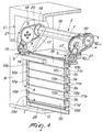
- the apparatus 2 comprises a motorized roller 16, for example by means of a respective electric motor, which can in turn be actuated by the user, with an external button or even in another manner, as a function of the specific practical requirements.
- the roller 16 rotates about its own horizontal axis of symmetry F (shown for the sake of simplicity only in Figures 4 and 9 ); the roller 16 is coupled to the connecting slat 3b by means of at least one belt 17 (and preferably two), so as to actuate the movement of the plurality of slats 3a, 3b, 3c, 3d between the inactive and active configurations.
- the slats 3a, 3b, 3c, 3d can in any case be arranged (at least partially) side by side in the compartment B or, preferably, wound (almost completely) around such roller 16, so as to be able to contain the dimensions of such compartment B.
- the cam 5 also is rotated by the motorized roller 16 by way of respective transmission and speed reduction elements, which are supported by plates 18 that are fixed to the walls C by means of bolts 19.
- such elements can comprise a ring 20, which is coaxial to the roller 16 and is associated with a speed reduction block 21.
- each slat 3a, 3b, 3c, 3d has at least one axial shank 22a, 22b, 22c, 22d, which protrudes from a respective end portion; it should also be noted that in view of the preferably mirror-symmetrical structure of the shutter 1, equally preferably each slat 3a, 3b, 3c, 3d has two axial shanks 22a, 22b, 22c, 22d, each of which protrudes from a respective end portion.
- Each pinion 8, which meshes with the respective rack 7, is therefore shaped by a respective shank 22a ( Figure 14 ).
- shank 22b of the connecting slat 3b ( Figures 11 and 12 ) has at least one portion 23b that has a prism-like transverse cross-section that is complementary to a respective orifice 24b provided in the corresponding slider 11b ( Figure 11 ).
- the shutter 1 can comprise, in addition to one or more active rotating slats 3a, also a connecting slat 3b, which cannot rotate: it should be noted that it is intended to remain often concealed from view, sometimes even external to the opening A, in the active configuration, and therefore the possibility to rotate would be useless or detrimental.
- the connecting slat 3b indeed performs the role of connection interface with the speed reduction block 21 and the cam 5.
- At least one intermediate slat 3c is interposed between the connecting slat 3b and the series of active slats 3a.
- Such intermediate slat 3c is used to transfer the vertical stress imparted by the pusher pin 9 to the slider elements 12a (through the corresponding slider element 12c) and it is possible to resort to it when one wishes to keep the active slats 3a (the only ones that rotate) even more spaced from the connecting slat 3b.
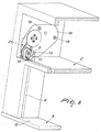
- the roll-up shutter 1 also comprises an end slat 3d, which is arranged on the opposite side with respect to the connecting slat 3b and is coupled even indirectly, in a downward region, to a compensation bar 25.
- a compensation bar 25 is indeed the possibility that the opening A might be closed completely by the slats 3a, 3b, 3c, 3d alone.
- the shank 22d of the end slat 3d has a portion 23d that has a prism-like transverse cross-section which is complementary to a respective slit 24d ( Figures 15 and 16 ) provided in the corresponding shoulder 10d ( Figure 16 ), in order to hinder the rotation of the end slat 3d (indeed allowing only the active slat 3b to rotate, as can be deduced from Figure 3 ).
- the compensation bar 25 has two protruding teeth 26 ( Figure 17 ), which are inserted so that they can slide in respective elongated slots 27 provided along the shoulders 10d of the end slat 3d ( Figures 15 and 16 ).
- the sliding coupling between the teeth 26 and the slots 27 allows the possibility of (free) variation of the relative position and inclination of the bar 25 with respect to the end slat 3d: therefore, when the bar 25 touches the threshold G, it can adapt automatically to any imperfections thereof, in any case ensuring complete closure (and without holes or gaps) of the opening A.
- the actuated rotation of the motorized roller 16 allows to raise or lower the slats 3a, 3b, 3c, 3d and to provide the inactive configuration and/or the active configuration; the connecting slat 3b is in fact coupled to the roller 16 by means of the belts 17, while the other slats 3a, 3c, 3d move with the connecting slat 3b by way of the (rotary) coupling provided at the shoulders 10a, 10b, 10c, 10d and at the sliders 11a, 11b, 11c, 11d.
- the pins 9, 14 are located respectively at the inlet of the slots 13, 15 provided on the cam 5 (which also is moved by the roller 16).
- a further rotation of the roller 16 then causes the pusher pin 9 to approach progressively the reference pin 14 (which in practice is kept stationary by the shape of the respective second slot 15).
- the relative motion is transmitted to the entire slider assembly 4, since the pusher pin 9 is formed directly by the slider element 12b of the connecting slat 3b, and the other slider elements 12a, 12c are coupled (rotatably) to the first one, without the possibility to perform other movements (except indeed the sliding motion).
- the rotation angle allowed to the active slats 3a can be chosen freely, by varying the dimensions and in general the dimensional parameters of the components involved; for example, an oscillation about the longitudinal axis D of an angular breadth equal to 120° is allowed.
- Other constructive choices, as a function of the specific requirements, are in any case not excluded.
- a rotation in the opposite direction of the roller 16 initially causes the sliding of the pins 9, 14 in the opposite direction, along the slots 13, 15, with consequent reclosure of the slots 6.
- the additional rotation lifts the slats 3a, 3b, 3c, 3d, sending them again toward the inactive configuration.
- the high versatility of the shutter 1 according to the invention is further increased by resorting to the compensation bar 25 and to the sliding coupling between its teeth 26 and the slots 27 provided along the shoulders 10d: the bar 25 can in fact easily close even openings A the thresholds G of which are uneven or have geometric imperfections.
- the compensation bar 25 ensures complete closure of the opening A, even in case of irregularities, while obviously the number of slats 3a, 3b, 3c, 3d can be chosen easily, as a function of the dimensions of such opening A and of the specific requirements, ensuring optimum replacement.
- the second slot 15 contrasts the movement of the reference pin 14 and therefore also any attempt to lift the entire shutter 1, which turns out to be reliable and capable of withstanding break-in attempts.
- the materials used, as well as the dimensions, may be any according to requirements and to the state of the art.
Landscapes
- Engineering & Computer Science (AREA)
- Structural Engineering (AREA)
- Architecture (AREA)
- Civil Engineering (AREA)
- Operating, Guiding And Securing Of Roll- Type Closing Members (AREA)
Priority Applications (1)
| Application Number | Priority Date | Filing Date | Title |
|---|---|---|---|
| EP16425010.2A EP3205809A1 (de) | 2016-02-15 | 2016-02-15 | Rollladen mit drebaren leisten |
Applications Claiming Priority (1)
| Application Number | Priority Date | Filing Date | Title |
|---|---|---|---|
| EP16425010.2A EP3205809A1 (de) | 2016-02-15 | 2016-02-15 | Rollladen mit drebaren leisten |
Publications (1)
| Publication Number | Publication Date |
|---|---|
| EP3205809A1 true EP3205809A1 (de) | 2017-08-16 |
Family
ID=55701909
Family Applications (1)
| Application Number | Title | Priority Date | Filing Date |
|---|---|---|---|
| EP16425010.2A Withdrawn EP3205809A1 (de) | 2016-02-15 | 2016-02-15 | Rollladen mit drebaren leisten |
Country Status (1)
| Country | Link |
|---|---|
| EP (1) | EP3205809A1 (de) |
Cited By (4)
| Publication number | Priority date | Publication date | Assignee | Title |
|---|---|---|---|---|
| IT201700112700A1 (it) * | 2017-10-06 | 2019-04-06 | Centro Avvolgibili Di G Costanzo & C Snc | Tapparella avvolgibile a sistema desmodromico |
| IT201800002859A1 (it) * | 2018-02-20 | 2019-08-20 | Giovanni Mancuso | Tapparella avvolgibile a lamelle orientabili e distanziabili |
| IT202000001537A1 (it) | 2020-01-27 | 2020-04-27 | Fazio Vincenzo De | Tapparella avvolgibile a lamelle orientabili |
| IT202000012691A1 (it) * | 2020-05-28 | 2021-11-28 | P E I Protezioni Elaborazioni Ind S R L | Apparato di protezione per una macchina utensile. |
Citations (3)
| Publication number | Priority date | Publication date | Assignee | Title |
|---|---|---|---|---|
| DE19842502A1 (de) * | 1998-09-17 | 2000-05-25 | Fennel Gmbh | Jalousierbarer Rolladen |
| WO2012065917A1 (en) * | 2010-11-15 | 2012-05-24 | Luxe Perfil S.L. | System of slats adjustable by rotation |
| EP2722475A1 (de) * | 2012-10-19 | 2014-04-23 | Teknalsystem S.r.l. | Rollladen mit Kipplamellen |
-
2016
- 2016-02-15 EP EP16425010.2A patent/EP3205809A1/de not_active Withdrawn
Patent Citations (3)
| Publication number | Priority date | Publication date | Assignee | Title |
|---|---|---|---|---|
| DE19842502A1 (de) * | 1998-09-17 | 2000-05-25 | Fennel Gmbh | Jalousierbarer Rolladen |
| WO2012065917A1 (en) * | 2010-11-15 | 2012-05-24 | Luxe Perfil S.L. | System of slats adjustable by rotation |
| EP2722475A1 (de) * | 2012-10-19 | 2014-04-23 | Teknalsystem S.r.l. | Rollladen mit Kipplamellen |
Cited By (7)
| Publication number | Priority date | Publication date | Assignee | Title |
|---|---|---|---|---|
| IT201700112700A1 (it) * | 2017-10-06 | 2019-04-06 | Centro Avvolgibili Di G Costanzo & C Snc | Tapparella avvolgibile a sistema desmodromico |
| EP3508681A1 (de) * | 2017-10-06 | 2019-07-10 | Centro Avvolgibili G. Costanzo & C. s.n.c. | Rollladen mit einem desmodromischen system |
| IT201800002859A1 (it) * | 2018-02-20 | 2019-08-20 | Giovanni Mancuso | Tapparella avvolgibile a lamelle orientabili e distanziabili |
| WO2019162797A1 (en) * | 2018-02-20 | 2019-08-29 | Giovanni Mancuso | Roller-shutter with orientable and spaceable slats |
| IT202000001537A1 (it) | 2020-01-27 | 2020-04-27 | Fazio Vincenzo De | Tapparella avvolgibile a lamelle orientabili |
| WO2021152644A1 (en) | 2020-01-27 | 2021-08-05 | Vincenzo De Fazio | Rolling shutter with adjustable slats |
| IT202000012691A1 (it) * | 2020-05-28 | 2021-11-28 | P E I Protezioni Elaborazioni Ind S R L | Apparato di protezione per una macchina utensile. |
Similar Documents
| Publication | Publication Date | Title |
|---|---|---|
| EP3205809A1 (de) | Rollladen mit drebaren leisten | |
| US8528255B2 (en) | Outward opening window unit | |
| CN106460455B (zh) | 设有防止百叶窗在运输或组装系统时移动的部件的封闭容纳于双层玻璃的软百叶窗等的系统 | |
| US20160230450A1 (en) | Closing element for roller shutter and movable wall for roller shutter comprising the closing element | |
| EP2722475B1 (de) | Rollladen mit Kipplamellen | |
| AU2004209892B2 (en) | Door shutter mechanism | |
| DK2835489T3 (en) | Roller shutters, which can act as blinds, with swivel blades | |
| EP2852730B1 (de) | Jalousie mit paarweise angeordneten lamellen, die untereinander verbundenen sind | |
| CN106460431A (zh) | 在枢转窗户处的机构 | |
| RS58863B1 (sr) | Pokretački uređaj letvica kapka za prozore | |
| WO2021070003A1 (en) | Roller shutter with orientable slats provided with a simplified means for angular rotation | |
| KR100696370B1 (ko) | 루버셔터 | |
| KR20130004711U (ko) | 전동 환기창 | |
| KR101442124B1 (ko) | 슬라이드 블럭형 발코니 블라인드 | |
| KR200340253Y1 (ko) | 개폐가 용이한 방범창 | |
| KR20180061627A (ko) | 미닫이형 이중창문 | |
| ITUB20156296A1 (it) | Tenda ad avvolgimento | |
| KR101536572B1 (ko) | 커튼 장치 | |
| KR101340623B1 (ko) | 블라인드 장치 | |
| KR20130024347A (ko) | 블라인드 | |
| KR20110097155A (ko) | 상하, 좌우, 전동식 무대 모형막 | |
| JPH0446062Y2 (de) | ||
| EP3692233B1 (de) | Zusammengesetzte schiebewand | |
| EP3508681A1 (de) | Rollladen mit einem desmodromischen system | |
| JP5420738B2 (ja) | 引戸装置 |
Legal Events
| Date | Code | Title | Description |
|---|---|---|---|
| PUAI | Public reference made under article 153(3) epc to a published international application that has entered the european phase |
Free format text: ORIGINAL CODE: 0009012 |
|
| AK | Designated contracting states |
Kind code of ref document: A1 Designated state(s): AL AT BE BG CH CY CZ DE DK EE ES FI FR GB GR HR HU IE IS IT LI LT LU LV MC MK MT NL NO PL PT RO RS SE SI SK SM TR |
|
| AX | Request for extension of the european patent |
Extension state: BA ME |
|
| STAA | Information on the status of an ep patent application or granted ep patent |
Free format text: STATUS: THE APPLICATION IS DEEMED TO BE WITHDRAWN |
|
| 18D | Application deemed to be withdrawn |
Effective date: 20180217 |