EP3205889B1 - Reihen-parallel hydraulisches ventil mit einem logikschaltelement - Google Patents
Reihen-parallel hydraulisches ventil mit einem logikschaltelement Download PDFInfo
- Publication number
- EP3205889B1 EP3205889B1 EP17155506.3A EP17155506A EP3205889B1 EP 3205889 B1 EP3205889 B1 EP 3205889B1 EP 17155506 A EP17155506 A EP 17155506A EP 3205889 B1 EP3205889 B1 EP 3205889B1
- Authority
- EP
- European Patent Office
- Prior art keywords
- switching element
- channel
- logic switching
- pressure
- valve
- Prior art date
- Legal status (The legal status is an assumption and is not a legal conclusion. Google has not performed a legal analysis and makes no representation as to the accuracy of the status listed.)
- Active
Links
Images



Classifications
-
- F—MECHANICAL ENGINEERING; LIGHTING; HEATING; WEAPONS; BLASTING
- F15—FLUID-PRESSURE ACTUATORS; HYDRAULICS OR PNEUMATICS IN GENERAL
- F15B—SYSTEMS ACTING BY MEANS OF FLUIDS IN GENERAL; FLUID-PRESSURE ACTUATORS, e.g. SERVOMOTORS; DETAILS OF FLUID-PRESSURE SYSTEMS, NOT OTHERWISE PROVIDED FOR
- F15B11/00—Servomotor systems without provision for follow-up action; Circuits therefor
- F15B11/16—Servomotor systems without provision for follow-up action; Circuits therefor with two or more servomotors
- F15B11/20—Servomotor systems without provision for follow-up action; Circuits therefor with two or more servomotors controlling several interacting or sequentially-operating members
-
- F—MECHANICAL ENGINEERING; LIGHTING; HEATING; WEAPONS; BLASTING
- F15—FLUID-PRESSURE ACTUATORS; HYDRAULICS OR PNEUMATICS IN GENERAL
- F15B—SYSTEMS ACTING BY MEANS OF FLUIDS IN GENERAL; FLUID-PRESSURE ACTUATORS, e.g. SERVOMOTORS; DETAILS OF FLUID-PRESSURE SYSTEMS, NOT OTHERWISE PROVIDED FOR
- F15B11/00—Servomotor systems without provision for follow-up action; Circuits therefor
- F15B11/16—Servomotor systems without provision for follow-up action; Circuits therefor with two or more servomotors
- F15B11/161—Servomotor systems without provision for follow-up action; Circuits therefor with two or more servomotors with sensing of servomotor demand or load
-
- F—MECHANICAL ENGINEERING; LIGHTING; HEATING; WEAPONS; BLASTING
- F15—FLUID-PRESSURE ACTUATORS; HYDRAULICS OR PNEUMATICS IN GENERAL
- F15B—SYSTEMS ACTING BY MEANS OF FLUIDS IN GENERAL; FLUID-PRESSURE ACTUATORS, e.g. SERVOMOTORS; DETAILS OF FLUID-PRESSURE SYSTEMS, NOT OTHERWISE PROVIDED FOR
- F15B13/00—Details of servomotor systems ; Valves for servomotor systems
- F15B13/02—Fluid distribution or supply devices characterised by their adaptation to the control of servomotors
- F15B13/06—Fluid distribution or supply devices characterised by their adaptation to the control of servomotors for use with two or more servomotors
-
- F—MECHANICAL ENGINEERING; LIGHTING; HEATING; WEAPONS; BLASTING
- F15—FLUID-PRESSURE ACTUATORS; HYDRAULICS OR PNEUMATICS IN GENERAL
- F15B—SYSTEMS ACTING BY MEANS OF FLUIDS IN GENERAL; FLUID-PRESSURE ACTUATORS, e.g. SERVOMOTORS; DETAILS OF FLUID-PRESSURE SYSTEMS, NOT OTHERWISE PROVIDED FOR
- F15B13/00—Details of servomotor systems ; Valves for servomotor systems
- F15B13/02—Fluid distribution or supply devices characterised by their adaptation to the control of servomotors
- F15B13/06—Fluid distribution or supply devices characterised by their adaptation to the control of servomotors for use with two or more servomotors
- F15B13/08—Assemblies of units, each for the control of a single servomotor only
-
- F—MECHANICAL ENGINEERING; LIGHTING; HEATING; WEAPONS; BLASTING
- F15—FLUID-PRESSURE ACTUATORS; HYDRAULICS OR PNEUMATICS IN GENERAL
- F15B—SYSTEMS ACTING BY MEANS OF FLUIDS IN GENERAL; FLUID-PRESSURE ACTUATORS, e.g. SERVOMOTORS; DETAILS OF FLUID-PRESSURE SYSTEMS, NOT OTHERWISE PROVIDED FOR
- F15B18/00—Parallel arrangements of independent servomotor systems
-
- F—MECHANICAL ENGINEERING; LIGHTING; HEATING; WEAPONS; BLASTING
- F15—FLUID-PRESSURE ACTUATORS; HYDRAULICS OR PNEUMATICS IN GENERAL
- F15B—SYSTEMS ACTING BY MEANS OF FLUIDS IN GENERAL; FLUID-PRESSURE ACTUATORS, e.g. SERVOMOTORS; DETAILS OF FLUID-PRESSURE SYSTEMS, NOT OTHERWISE PROVIDED FOR
- F15B2211/00—Circuits for servomotor systems
- F15B2211/20—Fluid pressure source, e.g. accumulator or variable axial piston pump
- F15B2211/205—Systems with pumps
- F15B2211/2053—Type of pump
- F15B2211/20538—Type of pump constant capacity
-
- F—MECHANICAL ENGINEERING; LIGHTING; HEATING; WEAPONS; BLASTING
- F15—FLUID-PRESSURE ACTUATORS; HYDRAULICS OR PNEUMATICS IN GENERAL
- F15B—SYSTEMS ACTING BY MEANS OF FLUIDS IN GENERAL; FLUID-PRESSURE ACTUATORS, e.g. SERVOMOTORS; DETAILS OF FLUID-PRESSURE SYSTEMS, NOT OTHERWISE PROVIDED FOR
- F15B2211/00—Circuits for servomotor systems
- F15B2211/30—Directional control
- F15B2211/305—Directional control characterised by the type of valves
- F15B2211/30525—Directional control valves, e.g. 4/3-directional control valve
- F15B2211/3053—In combination with a pressure compensating valve
- F15B2211/30535—In combination with a pressure compensating valve the pressure compensating valve is arranged between pressure source and directional control valve
-
- F—MECHANICAL ENGINEERING; LIGHTING; HEATING; WEAPONS; BLASTING
- F15—FLUID-PRESSURE ACTUATORS; HYDRAULICS OR PNEUMATICS IN GENERAL
- F15B—SYSTEMS ACTING BY MEANS OF FLUIDS IN GENERAL; FLUID-PRESSURE ACTUATORS, e.g. SERVOMOTORS; DETAILS OF FLUID-PRESSURE SYSTEMS, NOT OTHERWISE PROVIDED FOR
- F15B2211/00—Circuits for servomotor systems
- F15B2211/30—Directional control
- F15B2211/305—Directional control characterised by the type of valves
- F15B2211/3056—Assemblies of multiple valves
- F15B2211/3059—Assemblies of multiple valves having multiple valves for multiple output members
- F15B2211/30595—Assemblies of multiple valves having multiple valves for multiple output members with additional valves between the groups of valves for multiple output members
-
- F—MECHANICAL ENGINEERING; LIGHTING; HEATING; WEAPONS; BLASTING
- F15—FLUID-PRESSURE ACTUATORS; HYDRAULICS OR PNEUMATICS IN GENERAL
- F15B—SYSTEMS ACTING BY MEANS OF FLUIDS IN GENERAL; FLUID-PRESSURE ACTUATORS, e.g. SERVOMOTORS; DETAILS OF FLUID-PRESSURE SYSTEMS, NOT OTHERWISE PROVIDED FOR
- F15B2211/00—Circuits for servomotor systems
- F15B2211/30—Directional control
- F15B2211/31—Directional control characterised by the positions of the valve element
- F15B2211/3122—Special positions other than the pump port being connected to working ports or the working ports being connected to the return line
Definitions
- the present invention finds application in hydraulic valves and its object is the implementation of a dedicated hydraulic circuit for lifting applications in the presence of hydraulic valves with multiple functions intended for operating machines, such as front loaders, shovels, buckets.
- the invention relates to a logic element insertable inside said hydraulic circuit of control valves for utilities, wherein said logic element is capable of ensuring an overall operation of the circuit in series or in parallel depending on the operating conditions of the valve.
- the invention provides for multiple possibilities to solve and manage these operating conditions.
- EP 2 381 115 A describes a hydraulic circuit for a construction machine.
- the present invention aims to find a solution that allows, in a single circuit, the benefits of both configurations described to be obtained, as a function of the working conditions.
- One object of the present invention is to solve the limits of circuits for hydraulic valves in "series” ( fig. 1 ) and “parallel” ( fig. 2 ) intended for front loading circuits described above, with a simple, rational and rather cost-effective solution.
- the logic switching element ensures an overall operation of the circuit in series or in parallel depending on the plant operating conditions.
- the logic switching element is controlled by a sequence valve or by a pressure relief valve.
- the circuit ensures a more stable operation upon switching from series to parallel circuit and vice versa, thereby delegating the calibration of the sequence valve or the spool position as responsible for the switching of the logic element.
- valve and mixed series-parallel hydraulic circuit object of the present invention which is defined by the claims below.
- Fig. 3 shows the basic construction of the logic element E.
- the latter reaches the second position, which involves closing between channel S and P1 and the simultaneous opening of the parallel channel P towards branch P1.
- channel S is set to discharge by the connection with T.
- a control channel 1 is also part of the logic element E, which copies the signal from branch P and brings it on one side of the logic element. Furthermore, spring 2, which has the function of keeping the logic element in that neutral position and the calibration of which determines the pressure value P required for the switching of the logic element E.
- this logic element E is inserted in a complete hydraulic circuit for front loader, implementing in this way the circuit shown in Fig. 1 and 2 .
- Fig. 4 proposes the scheme in fig. 3 but with a different constructive solution.
- the logic element E1 is coupled with a sequence valve VS.
- Valve VS consists of a distributor CS associated with a spring 9, a pressure relief valve VM and relative connections.
- a control line 7 including two chokes 4 and 8 is added in the illustrated solution.
- spring 2a changes function with respect to spring 2 seen in fig. 3 .
- the logic element E1 in rest configuration involves the connection of S with P1, and since the pressure value on P is reported on both sides of the logic element by virtue of connections 1 and 6, this is guaranteed by the second spring 2a.
- the calibration value of valve VM set onto spring 5 is reached on P, this opens the connection of the control line 7 towards the discharge.
- distributor CS opens in position to set both branch controls 10 and 11 to discharge.
- the pressure difference generated by choke 4 causes the displacement of the logic element E1 to a second position, as the pressure value on channel 6 is lower than the value on channel 1.
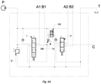
- this logic element E1 is inserted in a complete hydraulic circuit for front loader, implementing in this way the circuit shown in Fig. 1 and 2 .
- the sequence valve VS described in fig. 4 is schematized.
- the logic element E2 consists of a 6-way, 2 positions distributor. Connection 6a and 12 is added to channels P, S, T, P1, which remain the same as regards the connections as compared to the solutions shown above. In neutral position of the logic element, the two signals 6a and 12 are closed in the logic element. In switching position of element E2, channels 6a and 12 are connected through the element.
- Spring 2a is the same as in solution in fig. 4 , as well as channel 7, choke 4 and also the pressure relief valve VM and relative spring 5.
- the logic element E2 in rest configuration involves the connection of S with P1, and since the pressure value on P is reported on both sides of the logic element by virtue of connections 1 and 6, said connection is guaranteed by spring 2a. Once the calibration value of valve VM set onto spring 5 is reached on P, this opens the connection of the control line 7 towards the channel 14, not necessarily to discharge:
- Channel 14 is interrupted, the pressure increase on channels 14, 12, 6a, 6 results in the switching of the logic element E2 to neutral.
- Channel 13 is essential to prevent the increased pressure from reopening valve VM without having switched the logic element E2.
- this logic element E2 is inserted in a complete hydraulic circuit for front loader, implementing in this way the circuit shown in Fig. 1 and 2 .
- Fig. 6 the logic element E1 in fig. 4 is inserted in a complete hydraulic circuit for frontal loader similar to that in fig. 4A , but in this case repeated for a circuit with multiple sections, in this case 3.
Landscapes
- Engineering & Computer Science (AREA)
- Physics & Mathematics (AREA)
- Fluid Mechanics (AREA)
- Mechanical Engineering (AREA)
- General Engineering & Computer Science (AREA)
- Fluid-Pressure Circuits (AREA)
Claims (10)
- Hydraulisches Wegeventil, mit einem gemischten in Reihe (S) und parallel (P) angeordneten Hydraulikkreis, bestehend aus zwei oder mehr Abschnitten, die jeweils eine Spule (I, II, III) umfassen und durch in Reihe und parallel angeordneten Schaltungen miteinander verbunden werden können, wobei das Ventil Reihenkanäle (S) und Parallelkanäle (P) zur Reihen- bzw. Parallelschaltung umfasst, wobei der Parallelkanal einem Druckkanal des Ventils entspricht, dadurch gekennzeichnet, dass das Ventil ein Schaltlogikelement (E, E1, E2) mit einem Verteiler UMFASST, wobei das Schaltlogikelement (E, E1, E2) in einer Neutralstellung die Verbindung des Reihenkanals (S) des gemischten in Reihe und parallel angeordneten Hydraulikkreis mit einem nachgeschalteten Druckzweig (P1) stromabwärts des Schaltlogikkreises (E, E1, E2) positioniert ist und in Verbindung mit einer Spule (II) stromabwärts des Schaltlogikelements (E, E1, E2) ist, und gleichzeitig einen Druckzweig des Parallelkanals aus einer Parallelschaltung und einem Ableitungszweig (T) isoliert; wobei beim Umschalten des Verteilers des Schaltlogikelements (E, E1, E2), gelangt dieses in eine zweite Stellung, in der der Serienkanal (S) geschlossen und gleichzeitig der Parallelkanal (P) zum nachgeschalteten Druckzweig (P1) geöffnet ist, und in der zweiten Position ist der Reihenkanal (S) auf Entladung durch Verbindung mit dem Entladungszweig (T) eingestellt; wobei das Schaltlogikelement (E) einen Steuerkanal (1) umfasst, der das Signal des Druckkanals (P) auf einer Seite des Schaltlogikelements (E, E1, E2) führt, und eine Feder (2; 2a) umfasst, die auf einer Seite angeordnet ist, die derjenigen gegenüberliegt, in der sich der Druckkanal (P) geführt wird, wobei das Schaltlogikelement (E) durch die Feder (2) in der neutralen Position gehalten wird, wodurch ein Kalibrierungswert der Feder (2) den Druckwert im Steuerkanal (1) zum Schalten des Schaltlogikelements (E) von der Neutralstellung in die genannte zweite Stellung, bestimmt.
- Ventil nach Anspruch 1, dadurch gekennzeichnet, dass das Umschalten des Schaltlogikelements (E1) durch ein mit dem Schaltlogikelement (E1) gekoppeltes Folgeventil (VS) gesteuert wird, das durch einen weiteren mit diesem verbundenen Folgeverteiler (CS) mit einer Feder (9) und einem Druckbegrenzungsventil (VM) verbunden ist; wobei das Folgeventil (VS) zwei unterschiedliche Schaltdrücke des Schaltlogikelements (E1) und des Folgeventils (CS) definiert:a. es öffnet, sobald der Kalibrierungswert einer weiteren Folgefeder (5) des Druckentlastungsventils (VM) des Folgeventils (VS) erreicht ist;b. es schließt erst, wenn der Druckwert auf einem ersten Steuersignal (10) unter die Kalibrierung einer dem nachfolgenden Verteiler (CS) zugeordneten Feder (9) fällt, wobei das Steuersignal (10) der Feder des nachfolgenden Verteilers (CS) entgegengesetzt ist, wobei der Druckwert der Feder (9) des nachfolgenden Verteilers (CS) niedriger ist als der Wert der nachfolgenden Feder (5) des Druckentlastungsventils (VM) .
- Ventil nach Anspruch 2, dadurch gekennzeichnet, dass es eine Steuerleitung (7) mit zwei Drosseln (4, 8) aufweist; wobei der nachfolgende Verteiler (CS) ein zweites Steuersignal (11) aufweist, wobei zwischen den beiden folgenden Steuersignalen (10, 11) des nachfolgenden Verteilers (CS) eine erste Drossel (8) angeordnet ist; wobei das Schaltlogikelement (E1) im Ruhezustand durch die Wirkung der Feder (2a) des Schaltlogikelements (E1) den Reihenkanal (S) mit dem stromabwärtigen Druckzweig (P1) verbindet, wobei der Wert des Druckkanals (P) auf beiden Seiten des Schaltlogikelements (E1) durch den Steuerkanal (1) und einen zweiten Steuerkanal (6) dargestellt wird; wobei das Druckentlastungsventil (VM) so konfiguriert ist, dass es die Verbindung der Steuerleitung (7) zum Auslass (T) öffnet, sobald der Kalibrierungswert des Druckentlastungsventils (VM) an der Feder (5) der Druckentlastungventils (VM) am Druckkanal (P) erreicht wird:- der nachfolgende Verteiler (CS) öffnet zum Ablassen, abhängig von der von der Drossel (8) erzeugten Druckdifferenz auf die beiden Steuersignale (10, 11),- die von einer zweiten Drossel (4) erzeugte Druckdifferenz führt dazu, dass das Schaltlogikelement (E1) in eine zweite Stellung verlagert wird, wenn der Druckwert am zweiten Steuerkanal (6) niedriger als der Wert am Steuerkanal (1) ist,- wobei durch das Schließen des Druckentlastungsventils (VM) keine erneute Bewegung des Schaltlogikelements (E1) bewirkt wird; das nachfolgende Verteiler (CS) bleibt aufgrund der Druckdifferenz an den beiden Steuersignalen (10, 11) in der Signalauslassstellung.
- Ventil nach Anspruch 1, dadurch gekennzeichnet, dass das Umschalten des Schaltlogikelements (E2) wie folgt gesteuert wird:a. beim Öffnen, durch ein Druckentlastungsventil (VM) mit einer relativen Feder (5), das mit dem Schaltlogikelement (E2) gekoppelt ist; wobei das Druckentlastungsventil (VM) so konfiguriert ist, dass es eine Verbindung von einer Steuerleitung (7) zu einem Kanal (14) öffnet, der so eingestellt ist, dass er durch die Spule (II) stromabwärts des Schaltlogikelements entlädt und das Schalten des Schaltlogikelements (E2) ermöglicht;b. beim Schließen, durch einen weiteren Anschluss (6a, 12) am Schaltlogikelement (E2), der das Druckentlastungsventil (VM) umgeht, und durch die Unterbrechung des Kanals (14), die einen Druckanstieg auf dem Kanal (14) bewirkt, das Schaltlogikelement (E2) in eine neutrale Position schaltet;c. einen nachfolgenden Kanal (13), der mit dem Druckentlastungsventil (VM) verbunden ist, und durch Abzweigen eines Anschlusses (12) dieser nachfolgenden Anschlüsse verhindert wird, dass der erhöhte Druck das Druckentlastungsventil (VM) erneut öffnet, ohne dass das Schaltlogikelement (E2)umgeschaltet wurde.
- Ventil nach Anspruch 4, dadurch gekennzeichnet, dass die beiden nachfolgenden Anschlüsse (6a12) im Schaltlogikelement (E2) geschlossen sind, wenn sich das Schaltlogikelement (E2) in einer Neutralstellung befindet, während in der Schaltstellung des Schaltlogikelements (E2) werden die nachfolgenden Anschlüsse (6a, 12) über das Schaltlogikelement selbst verbunden.
- Ventil nach Anspruch 4, dadurch gekennzeichnet, dass es eine Drossel (4) am jeweiligen Verbindungskanal (7) des Parallelkanals (P) mit dem Druckentlastungsventil (VM) aufweist.
- Ventil nach den Ansprüchen 4 und 6, dadurch gekennzeichnet, dass bei geschaltetem Schaltlogikelement (E2) und geschlossenem Druckentlastungsventil (VM), bleibt die Verbindung zwischen den nachfolgenden Anschlüssen (6a, 12) im Schaltlogikelement, welches das Druckentlastungsventil (VM) umgeht, geöffnet und es wird keine Bewegung des Schaltlogikelements (E2) verursacht.
- Ventil nach den Ansprüchen 4 und 6, dadurch gekennzeichnet, dass das Schaltlogikelement (E2) in der Ruhekonfiguration die Verbindung der Reihenkanäle (S) mit dem stromabwärtigen Zweig (P1) beinhaltet; da der Druckwert am Druckkanal (P) aufgrund der Steuerkanäle (1, 6) auf beiden Seiten des Schaltlogikelements dargestellt wird, wird solche Verbindung durch die Feder (2a) des Schaltlogikelements sichergestellt, sobald der an der Feder (5) des Druckentlastungsventils (VM) am Parallelkanal (P) eingestellte Kalibrierungswert des Druckentlastungsventils (VM) erreicht, öffnet dies die Verbindung von der Steuerleitung (7) zum Kanal (14), wobei letzteres nicht unbedingt auf Entlastung festgelegt ist; in dieser Konfiguration:a. bei geschlossenem Kanal (14) öffnet das Schaltlogikelement (E2) an der Spule stromabwärts des Druckbegrenzungsventils (VM) nicht,b. wird der Kanal (14) auf Entladung über die Spule (II) eingestellt, bewirkt die durch die Drossel (4) erzeugte Druckdifferenz, dass das Schaltlogikelement (E2) in eine zweite Position verlagert wird, wenn der Druckwert am Kanal (6) kleiner als der Wert auf Kanal (1) ist.
- Ventil nach einem der vorhergehenden Ansprüche, wobei das Schaltlogikelement einen 4-Wege-2-Positionen-Verteiler aufweist, bei dem die Feder (2) des Schaltlogikelements das Schaltlogikelement in der Ruhestellung hält, bei dem Reihenkanälen (S) mit dem Zweig (P1) verbunden sind.
- Frontlader umfassend eine Ventileinrichtung nach mindestens einem der vorhergehenden Ansprüche.
Applications Claiming Priority (1)
| Application Number | Priority Date | Filing Date | Title |
|---|---|---|---|
| ITUB2016A000596A ITUB20160596A1 (it) | 2016-02-09 | 2016-02-09 | Valvola oleodinamica serie e parallelo con elemento logico di commutazione |
Publications (2)
| Publication Number | Publication Date |
|---|---|
| EP3205889A1 EP3205889A1 (de) | 2017-08-16 |
| EP3205889B1 true EP3205889B1 (de) | 2024-10-30 |
Family
ID=55948966
Family Applications (1)
| Application Number | Title | Priority Date | Filing Date |
|---|---|---|---|
| EP17155506.3A Active EP3205889B1 (de) | 2016-02-09 | 2017-02-09 | Reihen-parallel hydraulisches ventil mit einem logikschaltelement |
Country Status (2)
| Country | Link |
|---|---|
| EP (1) | EP3205889B1 (de) |
| IT (1) | ITUB20160596A1 (de) |
Citations (3)
| Publication number | Priority date | Publication date | Assignee | Title |
|---|---|---|---|---|
| JPH0571404U (ja) * | 1992-02-28 | 1993-09-28 | 株式会社タダノ | 作業車の走行用油圧回路 |
| US5335499A (en) * | 1992-09-24 | 1994-08-09 | Viking Engineering & Development, Incorporated | Multiple hydraulic actuators with series/parallel operation |
| US20040228733A1 (en) * | 2003-04-15 | 2004-11-18 | Riccardo Mares | Series-parallel hydrostatic transmission |
Family Cites Families (7)
| Publication number | Priority date | Publication date | Assignee | Title |
|---|---|---|---|---|
| DE3139635A1 (de) * | 1981-10-06 | 1983-04-21 | Robert Bosch Gmbh, 7000 Stuttgart | Hydraulische steuereinrichtung mit mindestens zwei wegeventilen zur steuerung hydraulischer verbraucher |
| SE522173C2 (sv) * | 2001-07-05 | 2004-01-20 | Hydrauto Valves Ab | Prioritetsventil |
| JP4193830B2 (ja) * | 2005-09-02 | 2008-12-10 | コベルコ建機株式会社 | 作業機械の油圧制御装置 |
| US8707690B2 (en) * | 2008-12-24 | 2014-04-29 | Doosan Infracore Co., Ltd. | Hydraulic pump controller for construction machine |
| WO2012125792A2 (en) * | 2011-03-15 | 2012-09-20 | Husco International, Inc. | Multiple function hydraulic system with a variable displacement pump and a hydrostatic pump-motor |
| JP6004900B2 (ja) * | 2012-11-07 | 2016-10-12 | Kyb株式会社 | パワーショベルの流体圧制御装置 |
| JP6235917B2 (ja) * | 2014-01-23 | 2017-11-22 | 川崎重工業株式会社 | 液圧駆動システム |
-
2016
- 2016-02-09 IT ITUB2016A000596A patent/ITUB20160596A1/it unknown
-
2017
- 2017-02-09 EP EP17155506.3A patent/EP3205889B1/de active Active
Patent Citations (3)
| Publication number | Priority date | Publication date | Assignee | Title |
|---|---|---|---|---|
| JPH0571404U (ja) * | 1992-02-28 | 1993-09-28 | 株式会社タダノ | 作業車の走行用油圧回路 |
| US5335499A (en) * | 1992-09-24 | 1994-08-09 | Viking Engineering & Development, Incorporated | Multiple hydraulic actuators with series/parallel operation |
| US20040228733A1 (en) * | 2003-04-15 | 2004-11-18 | Riccardo Mares | Series-parallel hydrostatic transmission |
Also Published As
| Publication number | Publication date |
|---|---|
| ITUB20160596A1 (it) | 2017-08-09 |
| EP3205889A1 (de) | 2017-08-16 |
Similar Documents
| Publication | Publication Date | Title |
|---|---|---|
| CN101003977B (zh) | 作业机械的液压控制装置 | |
| EP1178157B1 (de) | Hydraulische antriebsanordnung für eine zivilbau- oder erdbewegungsmaschine. | |
| US7513109B2 (en) | Hydraulic controller for working machine | |
| US11692332B2 (en) | Hydraulic control system | |
| US20180127949A1 (en) | Hydraulic circuit and working machine | |
| US20200232482A1 (en) | Hydraulic circuit | |
| WO2012129042A1 (en) | Regeneration circuit | |
| GB2536177A (en) | Fluidic system | |
| KR100226281B1 (ko) | 가변우선장치 | |
| EP3205889A1 (de) | Reihen-parallel hydraulisches ventil mit einem logikschaltelement | |
| CN110486341B (zh) | 液压控制系统以及移动式工作设备 | |
| EP0704630B1 (de) | Variables Folgeventil für schwere Baumaschinen | |
| CN212924200U (zh) | 新型起重机液压阀组 | |
| JP3803186B2 (ja) | 複数アクチュエータの油圧回路構成及びこの油圧回路を備えた掘削アタッチメント | |
| US7117670B2 (en) | Control device | |
| JP2018054031A (ja) | 作業車両用油圧制御装置 | |
| CN111364550A (zh) | 分体式液压多路换向阀系统和挖掘机 | |
| US20150089935A1 (en) | Control valve apparatus of power shovel | |
| JP2002004339A (ja) | 油圧ショベルの制御回路 | |
| KR200257578Y1 (ko) | 굴삭기의붐작동용유량제어장치 | |
| RU78536U1 (ru) | Гидрораспределитель секционный | |
| EP3744984B1 (de) | Oleodynamisches ventil | |
| JPS608162Y2 (ja) | 油圧制御装置 | |
| JP2003287002A (ja) | 作業用機械における油圧回路 | |
| JP2002081405A (ja) | 作業用機械における油圧回路 |
Legal Events
| Date | Code | Title | Description |
|---|---|---|---|
| PUAI | Public reference made under article 153(3) epc to a published international application that has entered the european phase |
Free format text: ORIGINAL CODE: 0009012 |
|
| STAA | Information on the status of an ep patent application or granted ep patent |
Free format text: STATUS: THE APPLICATION HAS BEEN PUBLISHED |
|
| AK | Designated contracting states |
Kind code of ref document: A1 Designated state(s): AL AT BE BG CH CY CZ DE DK EE ES FI FR GB GR HR HU IE IS IT LI LT LU LV MC MK MT NL NO PL PT RO RS SE SI SK SM TR |
|
| AX | Request for extension of the european patent |
Extension state: BA ME |
|
| STAA | Information on the status of an ep patent application or granted ep patent |
Free format text: STATUS: REQUEST FOR EXAMINATION WAS MADE |
|
| 17P | Request for examination filed |
Effective date: 20180216 |
|
| RBV | Designated contracting states (corrected) |
Designated state(s): AL AT BE BG CH CY CZ DE DK EE ES FI FR GB GR HR HU IE IS IT LI LT LU LV MC MK MT NL NO PL PT RO RS SE SI SK SM TR |
|
| STAA | Information on the status of an ep patent application or granted ep patent |
Free format text: STATUS: EXAMINATION IS IN PROGRESS |
|
| 17Q | First examination report despatched |
Effective date: 20191212 |
|
| GRAP | Despatch of communication of intention to grant a patent |
Free format text: ORIGINAL CODE: EPIDOSNIGR1 |
|
| STAA | Information on the status of an ep patent application or granted ep patent |
Free format text: STATUS: GRANT OF PATENT IS INTENDED |
|
| INTG | Intention to grant announced |
Effective date: 20240521 |
|
| GRAS | Grant fee paid |
Free format text: ORIGINAL CODE: EPIDOSNIGR3 |
|
| GRAA | (expected) grant |
Free format text: ORIGINAL CODE: 0009210 |
|
| STAA | Information on the status of an ep patent application or granted ep patent |
Free format text: STATUS: THE PATENT HAS BEEN GRANTED |
|
| AK | Designated contracting states |
Kind code of ref document: B1 Designated state(s): AL AT BE BG CH CY CZ DE DK EE ES FI FR GB GR HR HU IE IS IT LI LT LU LV MC MK MT NL NO PL PT RO RS SE SI SK SM TR |
|
| REG | Reference to a national code |
Ref country code: GB Ref legal event code: FG4D |
|
| REG | Reference to a national code |
Ref country code: CH Ref legal event code: EP |
|
| REG | Reference to a national code |
Ref country code: IE Ref legal event code: FG4D |
|
| REG | Reference to a national code |
Ref country code: DE Ref legal event code: R096 Ref document number: 602017085744 Country of ref document: DE |
|
| REG | Reference to a national code |
Ref country code: LT Ref legal event code: MG9D |
|
| P01 | Opt-out of the competence of the unified patent court (upc) registered |
Free format text: CASE NUMBER: APP_3574/2025 Effective date: 20250122 |
|
| REG | Reference to a national code |
Ref country code: NL Ref legal event code: MP Effective date: 20241030 |
|
| PG25 | Lapsed in a contracting state [announced via postgrant information from national office to epo] |
Ref country code: HR Free format text: LAPSE BECAUSE OF FAILURE TO SUBMIT A TRANSLATION OF THE DESCRIPTION OR TO PAY THE FEE WITHIN THE PRESCRIBED TIME-LIMIT Effective date: 20241030 Ref country code: PT Free format text: LAPSE BECAUSE OF FAILURE TO SUBMIT A TRANSLATION OF THE DESCRIPTION OR TO PAY THE FEE WITHIN THE PRESCRIBED TIME-LIMIT Effective date: 20250228 Ref country code: IS Free format text: LAPSE BECAUSE OF FAILURE TO SUBMIT A TRANSLATION OF THE DESCRIPTION OR TO PAY THE FEE WITHIN THE PRESCRIBED TIME-LIMIT Effective date: 20250228 |
|
| PG25 | Lapsed in a contracting state [announced via postgrant information from national office to epo] |
Ref country code: FI Free format text: LAPSE BECAUSE OF FAILURE TO SUBMIT A TRANSLATION OF THE DESCRIPTION OR TO PAY THE FEE WITHIN THE PRESCRIBED TIME-LIMIT Effective date: 20241030 Ref country code: NL Free format text: LAPSE BECAUSE OF FAILURE TO SUBMIT A TRANSLATION OF THE DESCRIPTION OR TO PAY THE FEE WITHIN THE PRESCRIBED TIME-LIMIT Effective date: 20241030 |
|
| REG | Reference to a national code |
Ref country code: AT Ref legal event code: MK05 Ref document number: 1737117 Country of ref document: AT Kind code of ref document: T Effective date: 20241030 |
|
| PG25 | Lapsed in a contracting state [announced via postgrant information from national office to epo] |
Ref country code: BG Free format text: LAPSE BECAUSE OF FAILURE TO SUBMIT A TRANSLATION OF THE DESCRIPTION OR TO PAY THE FEE WITHIN THE PRESCRIBED TIME-LIMIT Effective date: 20241030 |
|
| PG25 | Lapsed in a contracting state [announced via postgrant information from national office to epo] |
Ref country code: ES Free format text: LAPSE BECAUSE OF FAILURE TO SUBMIT A TRANSLATION OF THE DESCRIPTION OR TO PAY THE FEE WITHIN THE PRESCRIBED TIME-LIMIT Effective date: 20241030 |
|
| PG25 | Lapsed in a contracting state [announced via postgrant information from national office to epo] |
Ref country code: NO Free format text: LAPSE BECAUSE OF FAILURE TO SUBMIT A TRANSLATION OF THE DESCRIPTION OR TO PAY THE FEE WITHIN THE PRESCRIBED TIME-LIMIT Effective date: 20250130 |
|
| PG25 | Lapsed in a contracting state [announced via postgrant information from national office to epo] |
Ref country code: LV Free format text: LAPSE BECAUSE OF FAILURE TO SUBMIT A TRANSLATION OF THE DESCRIPTION OR TO PAY THE FEE WITHIN THE PRESCRIBED TIME-LIMIT Effective date: 20241030 Ref country code: GR Free format text: LAPSE BECAUSE OF FAILURE TO SUBMIT A TRANSLATION OF THE DESCRIPTION OR TO PAY THE FEE WITHIN THE PRESCRIBED TIME-LIMIT Effective date: 20250131 Ref country code: AT Free format text: LAPSE BECAUSE OF FAILURE TO SUBMIT A TRANSLATION OF THE DESCRIPTION OR TO PAY THE FEE WITHIN THE PRESCRIBED TIME-LIMIT Effective date: 20241030 |
|
| PG25 | Lapsed in a contracting state [announced via postgrant information from national office to epo] |
Ref country code: PL Free format text: LAPSE BECAUSE OF FAILURE TO SUBMIT A TRANSLATION OF THE DESCRIPTION OR TO PAY THE FEE WITHIN THE PRESCRIBED TIME-LIMIT Effective date: 20241030 |
|
| PG25 | Lapsed in a contracting state [announced via postgrant information from national office to epo] |
Ref country code: RS Free format text: LAPSE BECAUSE OF FAILURE TO SUBMIT A TRANSLATION OF THE DESCRIPTION OR TO PAY THE FEE WITHIN THE PRESCRIBED TIME-LIMIT Effective date: 20250130 |
|
| PG25 | Lapsed in a contracting state [announced via postgrant information from national office to epo] |
Ref country code: SM Free format text: LAPSE BECAUSE OF FAILURE TO SUBMIT A TRANSLATION OF THE DESCRIPTION OR TO PAY THE FEE WITHIN THE PRESCRIBED TIME-LIMIT Effective date: 20241030 |
|
| PG25 | Lapsed in a contracting state [announced via postgrant information from national office to epo] |
Ref country code: DK Free format text: LAPSE BECAUSE OF FAILURE TO SUBMIT A TRANSLATION OF THE DESCRIPTION OR TO PAY THE FEE WITHIN THE PRESCRIBED TIME-LIMIT Effective date: 20241030 |
|
| PG25 | Lapsed in a contracting state [announced via postgrant information from national office to epo] |
Ref country code: EE Free format text: LAPSE BECAUSE OF FAILURE TO SUBMIT A TRANSLATION OF THE DESCRIPTION OR TO PAY THE FEE WITHIN THE PRESCRIBED TIME-LIMIT Effective date: 20241030 |
|
| PG25 | Lapsed in a contracting state [announced via postgrant information from national office to epo] |
Ref country code: RO Free format text: LAPSE BECAUSE OF FAILURE TO SUBMIT A TRANSLATION OF THE DESCRIPTION OR TO PAY THE FEE WITHIN THE PRESCRIBED TIME-LIMIT Effective date: 20241030 |
|
| PG25 | Lapsed in a contracting state [announced via postgrant information from national office to epo] |
Ref country code: SK Free format text: LAPSE BECAUSE OF FAILURE TO SUBMIT A TRANSLATION OF THE DESCRIPTION OR TO PAY THE FEE WITHIN THE PRESCRIBED TIME-LIMIT Effective date: 20241030 |
|
| PG25 | Lapsed in a contracting state [announced via postgrant information from national office to epo] |
Ref country code: CZ Free format text: LAPSE BECAUSE OF FAILURE TO SUBMIT A TRANSLATION OF THE DESCRIPTION OR TO PAY THE FEE WITHIN THE PRESCRIBED TIME-LIMIT Effective date: 20241030 |
|
| REG | Reference to a national code |
Ref country code: DE Ref legal event code: R097 Ref document number: 602017085744 Country of ref document: DE |
|
| PLBE | No opposition filed within time limit |
Free format text: ORIGINAL CODE: 0009261 |
|
| STAA | Information on the status of an ep patent application or granted ep patent |
Free format text: STATUS: NO OPPOSITION FILED WITHIN TIME LIMIT |
|
| PG25 | Lapsed in a contracting state [announced via postgrant information from national office to epo] |
Ref country code: SE Free format text: LAPSE BECAUSE OF FAILURE TO SUBMIT A TRANSLATION OF THE DESCRIPTION OR TO PAY THE FEE WITHIN THE PRESCRIBED TIME-LIMIT Effective date: 20241030 |
|
| PG25 | Lapsed in a contracting state [announced via postgrant information from national office to epo] |
Ref country code: MC Free format text: LAPSE BECAUSE OF FAILURE TO SUBMIT A TRANSLATION OF THE DESCRIPTION OR TO PAY THE FEE WITHIN THE PRESCRIBED TIME-LIMIT Effective date: 20241030 |
|
| REG | Reference to a national code |
Ref country code: CH Ref legal event code: PL |
|
| 26N | No opposition filed |
Effective date: 20250731 |
|
| PG25 | Lapsed in a contracting state [announced via postgrant information from national office to epo] |
Ref country code: LU Free format text: LAPSE BECAUSE OF NON-PAYMENT OF DUE FEES Effective date: 20250209 |
|
| PG25 | Lapsed in a contracting state [announced via postgrant information from national office to epo] |
Ref country code: CH Free format text: LAPSE BECAUSE OF NON-PAYMENT OF DUE FEES Effective date: 20250228 |
|
| GBPC | Gb: european patent ceased through non-payment of renewal fee |
Effective date: 20250209 |
|
| REG | Reference to a national code |
Ref country code: BE Ref legal event code: MM Effective date: 20250228 |
|
| PG25 | Lapsed in a contracting state [announced via postgrant information from national office to epo] |
Ref country code: GB Free format text: LAPSE BECAUSE OF NON-PAYMENT OF DUE FEES Effective date: 20250209 |
|
| PG25 | Lapsed in a contracting state [announced via postgrant information from national office to epo] |
Ref country code: BE Free format text: LAPSE BECAUSE OF NON-PAYMENT OF DUE FEES Effective date: 20250228 |
|
| PG25 | Lapsed in a contracting state [announced via postgrant information from national office to epo] |
Ref country code: IE Free format text: LAPSE BECAUSE OF NON-PAYMENT OF DUE FEES Effective date: 20250209 |
|
| PGFP | Annual fee paid to national office [announced via postgrant information from national office to epo] |
Ref country code: DE Payment date: 20260218 Year of fee payment: 10 |
|
| PGFP | Annual fee paid to national office [announced via postgrant information from national office to epo] |
Ref country code: IT Payment date: 20260227 Year of fee payment: 10 |
|
| PGFP | Annual fee paid to national office [announced via postgrant information from national office to epo] |
Ref country code: FR Payment date: 20260218 Year of fee payment: 10 |