EP3205923B1 - Système de surveillance de purgeur de vapeur, dispositif de collecte de tube, et unité de purgeur de vapeur - Google Patents
Système de surveillance de purgeur de vapeur, dispositif de collecte de tube, et unité de purgeur de vapeur Download PDFInfo
- Publication number
- EP3205923B1 EP3205923B1 EP15849710.7A EP15849710A EP3205923B1 EP 3205923 B1 EP3205923 B1 EP 3205923B1 EP 15849710 A EP15849710 A EP 15849710A EP 3205923 B1 EP3205923 B1 EP 3205923B1
- Authority
- EP
- European Patent Office
- Prior art keywords
- sensor
- steam trap
- connection block
- pipe
- opening
- Prior art date
- Legal status (The legal status is an assumption and is not a legal conclusion. Google has not performed a legal analysis and makes no representation as to the accuracy of the status listed.)
- Active
Links
Images





Classifications
-
- F—MECHANICAL ENGINEERING; LIGHTING; HEATING; WEAPONS; BLASTING
- F16—ENGINEERING ELEMENTS AND UNITS; GENERAL MEASURES FOR PRODUCING AND MAINTAINING EFFECTIVE FUNCTIONING OF MACHINES OR INSTALLATIONS; THERMAL INSULATION IN GENERAL
- F16T—STEAM TRAPS OR LIKE APPARATUS FOR DRAINING-OFF LIQUIDS FROM ENCLOSURES PREDOMINANTLY CONTAINING GASES OR VAPOURS
- F16T1/00—Steam traps or like apparatus for draining-off liquids from enclosures predominantly containing gases or vapours, e.g. gas lines, steam lines, containers
- F16T1/38—Component parts; Accessories
- F16T1/48—Monitoring arrangements for inspecting, e.g. flow of steam and steam condensate
-
- F—MECHANICAL ENGINEERING; LIGHTING; HEATING; WEAPONS; BLASTING
- F16—ENGINEERING ELEMENTS AND UNITS; GENERAL MEASURES FOR PRODUCING AND MAINTAINING EFFECTIVE FUNCTIONING OF MACHINES OR INSTALLATIONS; THERMAL INSULATION IN GENERAL
- F16T—STEAM TRAPS OR LIKE APPARATUS FOR DRAINING-OFF LIQUIDS FROM ENCLOSURES PREDOMINANTLY CONTAINING GASES OR VAPOURS
- F16T1/00—Steam traps or like apparatus for draining-off liquids from enclosures predominantly containing gases or vapours, e.g. gas lines, steam lines, containers
- F16T1/02—Steam traps or like apparatus for draining-off liquids from enclosures predominantly containing gases or vapours, e.g. gas lines, steam lines, containers with valves controlled thermally
Definitions
- the present invention relates to a steam trap monitoring system. More particularly, the invention relates to a steam trap monitoring system having a steam trap, an opening/closing valve disposed on upstream side of the steam trap and configured to open/close a channel to the steam trap, a sensor for detecting one or more physical quantities, and an analysis unit for analyzing detection information from the sensor. The invention relates also to a pipe collection device using the system.
- an opening/closing valve In order to prevent entry of steam at time of e.g. repair or replacement of a steam trap, an opening/closing valve needs to be disposed on upstream side (entrance side) of the steam trap. In monitoring the steam trap, it is necessary to monitor not only whether the steam trap is functioning appropriately or not, but also a functional state of the opening/closing valve. e.g. for checking whether steam is leaking to the steam trap when the opening/closing valve is closed for stopping entry of steam to the steam trap.
- the principal object of this disclosure lies in resolving the above-described problem by enabling analysis of respective functional states of the steam trap and the opening/closing valve while reducing the number of sensors.
- a steam trap monitoring system relating to this disclosure comprises the technical features of independent claim 1.
- the senor comprises a vibration sensor for detecting vibration that propagates adjacent the steam trap and the opening/closing valve.
- vibration that propagates adjacent the steam trap and the opening/closing valve reflects mainly the functional state of the steam trap (e.g. whether steam leak is occurring or not), when the opening/closing valve is opened.
- the opening/closing valve is closed, entry of steam to the steam trap is stopped, so that no vibration occurs from the steam trap.
- the opening/closing valve effects its closing action normally, no vibration occurs from this opening/closing valve, either.
- steam leak will occur at the opening/closing valve, which leads to generation of vibration due to this steam leak.
- the sensor detects vibration if any that reflects the functional state of the steam trap, whereby the functional state of the steam trap can be analyzed.
- the opening/closing valve is under its closed state, it is possible to analyze the functional state of the opening/closing valve (whether it is effecting its closing operation normally or not) based on presence/absence of vibration. In this way, both the functional state of the steam trap and the functional state of the opening/closing valve can be analyzed appropriately.
- the senor further comprises a temperature sensor.
- connection block the steam trap, the opening/closing valve and the sensor are provided as a single unit
- the device structure can be simple. Further, if the steam trap and the opening/closing valve were disposed at separate locations via piping, this would require positioning the sensor at a location that allows analysis of the functional state of the steam trap and the functional state of the opening/closing valve.
- the steam trap can be removed from the connection block with keeping the connection between piping and the connection block as well as the attachment of the sensor to the connection block.
- the system can be advantageous also in the respect of maintenance such as inspection/repair.
- the operating portion of the opening/closing valve will be caused to face the rear side in association with the left-right orientation inversion of the connection block.
- this sensor due to requirement relating to communication and/or requirement relating to disposing space, it is preferred that this sensor be attached to the upper face of the connection block; and for the operating portion of the opening/closing valve, for requirement relating to its operation, it is preferred that this operating portion face the front side of the connection block. Therefore, the orientations of the sensor and the operating portion of the opening/closing valve should remain unchanged even when the left-right orientation of the connection block is inverted.
- the sensor is attached to the lower face side sensor attaching part caused to face substantially the upper side due to the upside-down inversion.
- the sensor can be attached substantially to the upper face portion of the connection block. In this way, the orientations of the sensor and the operating portion of the opening/closing valve can be same.
- connection block can be attached in a same manner even when it is attached to the pipes with left-right switchover between the position of the entrance side pipe connection port and the exit side pipe connection port due to upside-down inversion thereof.
- This arrangement can eliminate need to manufacture two kinds of connection blocks having the positions of their entrance-side pipe connection port and exit-side pipe connection port being inverted left and right from each other. Thus, there is achieved further advantage in terms of device cost.
- the blowdown valve is attached with utilization of one of the upper face side sensor attaching part and the lower face side sensor attaching part, which one sensor attaching part is located substantially in the lower face of the connection block and the sensor is not attached thereto.
- the blowdown valve attaching parts respectively in the upper face portion and the lower face portion of the connection block, separately from the upper face side sensor attaching part and the lower face side sensor attaching part.
- the structure of the connection block can be made simple, and also further device cost reduction is made possible.
- the sensor attaching portion is configured to not establish communication from a surface of the connection block to an inner channel of the connection block, to keep the sensor, when inserted, out of contact with fluid flowing in the inner channel of the connection block.
- an exit-side opening/closing valve disposed on a downstream side of the steam trap and configured to open/close the channel to the steam trap.
- both the upstream side channel and the downstream side channel for the steam trap can be closed by the (entrance side) opening/closing valve and the exit-side opening/closing valve.
- a pipe collection device in which a plurality of horizontally oriented branch pipes are connected to a vertically oriented main pipe, with the branch pipes being connected parallel with each other and distributed vertically; wherein the steam trap monitoring system of any one of the arrangements described above is applied to each of the branch pipes.
- the steam trap monitoring system capable of analyzing both a functional state of the steam trap and a functional state of the opening/closing valve by the single sensor provided for the two devices, i.e. the steam trap and the opening/closing valve is applied to a pipe collection device whose device configuration would otherwise tend to be complicated with provision of not only pipes, but also, the steam trap, the opening/closing valve, etc. Therefore, in comparison with an arrangement wherein a sensor 3 is provided respectively for both the steam trap 1 and the opening/closing valve 2, the number of sensors required can be reduced, whereby the whole device configuration can be made simple.
- a steam trap unit which does not form part of the invention comprises:
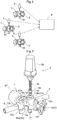
- Fig. 1 shows one example of a steam trap monitoring system relating to this disclosure.
- This steam trap monitoring system is constituted of a connection block 10 having a steam trap 1, a piston valve (opening/closing valve) 2 and a sensor 3, and an analysis device (corresponding to an "analysis unit") 4 for analyzing detection information from the sensor 3.
- connection block 10 defines entrance-side and exit-side pipe connection ports 10a, 10b which are coaxial and open in directions opposite to each other.
- the entrance-side pipe connection port 10a is connected to an entrance-side pipe 5 for guiding mixture fluid of steam and condensate, such as a condensate discharge channel of a steam using device; whereas, the exit-side pipe connection port 10b is connected to an exit-side pipe 6 as a condensate pipe for feeding condensate back to e.g. a boiler.
- a trap attaching seat 11 is formed, and the steam trap 1 is attached to this trap attaching seat 11.
- the trap attaching seat 11 there are apertured trap connection ports 12a, 13a respectively for an entrance-side inner channel 12 and an exit-side inner channel 13, which are formed in the connection block 10.
- the steam trap 1 as attached to the trap attaching seat 11 is communicated to the entrance-side pipe connection port 10a of the connection block 10 via the entrance-side inner channel 12 and also communicated to the exit-side pipe connection port 10b in the connection block 10 via the exit-side inner channel 13.
- the mixture fluid of steam and condensate flown into the entrance-side pipe 5 enters from the entrance-side pipe connection port 10a of the connection block 10 through the entrance-side inner channel 12 into the steam trap 1. Then, condensate separated from steam in the steam trap 1 is sent from the steam trap 1 through the exit-side inner channel 13 and the exit-side pipe connection port 10b of the connection block 10 into the exit-side pipe 6. Namely, of the mixture fluid of steam and condensate entering the entrance-side pipe 5, passage of steam is prevented by the steam trap 1 and condensate alone is returned to e.g. the boiler via the exit-side pipe 6.
- the trap connection port 12a of the entrance-side inner channel 12 is opened at the center of the trap attaching seat 11.
- the trap connection port 13a of the exit-side inner channel 13 is opened in the trap attaching seat 11 in an annular groove arrangement centering about the trap connection port 12a of the entrance-side inner channel 12.
- the steam trap 1 can be attached to the trap attaching seat 11 with appropriate communication to the trap connection ports 12a, 13a respectively of the entrance-side inner channel 12 and the exit-side inner channel 13, even when the steam trap 11 assumes a posture realized with upside-down orientation inversion thereof by being rotated 180 degrees about a front-rear axis p1 which extends through the center of the trap attaching seat 11.
- the piston valve 2 is provided integrally with the connection block 10 in such a manner as to open/close the entrance-side inner channel 12 of this connection block 10.
- An operating portion 2a of the entrance-side piston valve 2 projects obliquely forwardly under a horizontal posture from the front face portion of the connection block 10.
- the sensor 3 is inserted and attached to a sensor attaching portion 14 provided on the entrance side of the connection block 10. More particularly, the sensor attaching portion 14 consists of a dual-use attaching port 14a formed in the upper face portion of the connection block 10 and a dual-use attaching port 14b formed in the lower face portion of the connection block 10 in vertical symmetric layout relative to the dual-use attaching port 14a.
- the dual-use attaching ports 14a, 14b respectively are communicated from the surface of the connection block 10 to the entrance-side inner channel 12. Further, as shown in Fig.
- the dual-use attaching ports 14a, 14b are disposed with a center axis p2 of these dual-use attaching ports 14a, 14b being located at a position extending through an upstream vicinity of the piston valve 2.
- connection block 10 the steam trap 1, the piston valve 2 and the sensor 3 are configured to form a single steam trap unit, thus presenting a simple device structure.
- the sensor 3 is attached to the dual-use attaching port 14a formed in the upper face portion of the connection block 10, with a sensor attaching sheath pipe 15 (corresponding to a 'cover') being inserted into this dual-use attaching port 14a from above, and then the sensor 3 is inserted into this sensor attaching sheath pipe 15 from above.
- the dual-use attaching port 14b in the lower face portion of the connection block 10 is used as a blowdown valve attaching portion, so that a blowdown valve 16a for opening the entrance-side inner channel 12 to the atmosphere when necessary is attached to this dual-use attaching port 14b.
- a dual-use attaching port 17a is formed in the upper face portion of the connection block 10
- a dual-use attaching port 17b is formed in the lower face portion of the connection block 10 in vertical symmetric layout relative to the dual-use attaching port 17a.
- the dual-use attaching ports 17a, 17b respectively are communicated from the surface of the connection block 10 to the exit-side inner channel 13.
- this port 17a is closed with a plug or the like, whereas the blowdown valve 16b is attached to the dual-use attaching port 17b in the lower face portion of the connection block 10.
- a straightener 18 is provided integrally. This straightener 18 is disposed in the entrance-side inner channel 12 and between the piston valve 2 and the trap connection port 12a. A screen insertion/removal portion 18a of the straightener 18 is disposed on more exit side than the piston valve 2 and in the front face portion of the connection block 10.
- connection block 10 is configured to be attachable to the pipes 5, 6 even under a posture with the entrance-side pipe connection port 10a and the exit-side pipe connection port 10b being inverted left-right in their positions by upside-down inversion through rotation of the connection block 10 about the front-rear axis p1 extending perpendicularly to the pipes 5, 6.
- the connection block 10 is configured to be attachable to the pipes 5, 6 even under a posture with the entrance-side pipe connection port 10a and the exit-side pipe connection port 10b being inverted left-right in their positions by upside-down inversion through rotation of the connection block 10 about the front-rear axis p1 extending perpendicularly to the pipes 5, 6.
- the steam trap 1 is also attached to the trap attaching seat 11 of the connection block 10 with its upside-down inversion resulting from the rotation about the front-rear axis p1. With this, even in the event of left-right inversion by the upside-down inversion of the connection block 10, the steam trap 1 is placed under the same attaching posture as that shown in Fig. 2 and connected under such posture to the connection block 10.
- the entrance-side dual-use attaching port 14b in the lower face portion of the connection bock 10 which portion becomes substantially the upper face portion as the result of upside-down inversion is used as a sensor attaching portion, and to its entrance-side dual-use attaching port 14b, the sensor attaching sheath pipe 15 is inserted from above and then into this sensor attaching sheath pipe 15, the sensor 3 is attached by insertion thereof from above. With this, as the sheath pipe 15 covers the surface of the sensor 3, deterioration of the sensor 3 due to its contact with fluid (steam and/or condensate) can be prevented.
- this port 17b is closed by a plug or the like.
- the entrance-side and exit-side dual-use attaching ports 14a, 17a provided in the upper face portion of the connection block 10 which becomes substantially the lower face portion are used as blowdown valve attaching portions, so that the blowdown valves 16a, 16b are attached to these entrance-side and exit-side dual-use attaching ports 14a, 17a.
- connection block 10 is configured to be attachable to the pipes 5, 6 in a same manner even when the position of the entrance-side pipe connection port 10a and the position of the exit-side connection port 10b are inverted left and right by upside-down orientation inversion of the connection block 10.
- This arrangement can eliminate need to manufacture two kinds of connection blocks having the positions of their entrance-side pipe connection port 10a and exit-side pipe connection port 10b being inverted left and right from each other. Thus, there is achieved further advantage in terms of device cost.
- connection block for use in the steam trap monitoring system relating to this disclosure can be configured alternatively as a connection block 10' shown in Fig. 6 in which in addition to the piston valve 2, an exit-side piston valve (opening/closing valve) 19 for opening/closing the exit-side inner channel 13 is provided integrally with the connection block 10.
- an exit-side piston valve (opening/closing valve) 19 for opening/closing the exit-side inner channel 13 is provided integrally with the connection block 10.
- operating portions 2a, 19a respectively of the entrance-side and exit-side piston valves 2, 19 are caused to project obliquely forwardly from the front face portion of the connection block 10' under a horizontal posture in a V-shaped layout in their plane view, with the portions 2a, 19a being the farther from each other, the more forward side.
- the screen insertion/removal portion 18a of the straightener 18 is provided in the front face portion of the connection block 10' between the entrance-side piston valve 2 and the exit-side piston valve 19.
- the exit-side attaching ports 17a, 17b are disposed such that the center axis of the dual-use attaching ports 17a, 17b extends in the downstream vicinity of the piston valve 19.
- the rest of the configuration is identical to that of the foregoing connection block 10, so explanation thereof will be omitted herein.
- This further connection block 10' too is configured to be attachable to the pipes 5, 6, under the posture with the position of the entrance-side pipe connection port 10a and the position of the exit-side pipe connection port 10b being inverted left and right with the upside-down inversion thereof by way of the rotation about the front-rear axis p1 extending perpendicularly to the pipes 5, 6.
- connection block 10' to the pipes 5, 6 with the upside-down inversion by way of the rotation thereof about the front-rear axis p1
- the state of the steam trap 1 being directed to the rear side and the operating portions 2a, 19a of the piston valves 2, 19 being directed to the front side is maintained, and at the same time the fluid passing direction of the straightener 18 is caused to agree to the fluid passing direction from the pipe 5.
- the steam trap 1 too will be attached to the trap attaching seat 11 of the connection block 10', with the upside-down inversion by way of the rotation about the front-rear axis p1; and also the entrance-side attaching port 14b provided in the lower face portion of the connection block 10' which becomes substantially the upper face portion by the upside-down inversion is used as the sensor attaching portion, so that the sensor 3 is attached to this entrance-side attaching port 14b provided in the lower face portion.
- the steam trap 1 and the sensor 3 can be connected under the same posture to the connection port 10'.
- the sensor 3 includes an insertion portion 3a for insertion to the sensor attaching portion 14 having unillustrated vibration sensor and temperature sensor, a communication portion 3b for transmitting detection information (temperature, vibration) to the analysis device 4, and a heat exchanger tube 3c interconnecting the insertion portion 3a and the communication portion 3b.
- the sensor 3 detects vibration propagating if any adjacent the steam trap 1 and the piston valve 2 and also detects temperature adjacent the steam trap 1 and the piston valve 2. And, detected detection information (temperature, vibration) is transmitted from the communication portion 3b to the analysis device 4.
- the analysis device 4 analyzes both a functional state of the steam trap 1 and a functional state of the piston valve 2, based on the detected information transmitted from the respective sensor 3.
- this steam trap monitoring system for the two components, i.e. the steam trap 1 and the piston valve 2, one sensor 3 analyzes both the functional state of the steam trap 1 and the functional state of the piston valve 2.
- vibration propagating in the vicinity of the steam trap 1 and the piston valve 2 and detected by the vibration sensor of the sensor 3 reflects mainly the functional state of the steam trap 1 (e.g. whether steam leaking is occurring or not).
- the temperature adjacent the steam trap 1 and the piston valve 2 detected by the temperature sensor of the sensor 3 reflects the temperature of the steam trap 1.
- the piston valve 2 when the piston valve 2 is at its opened state, if the temperature detected by the temperature sensor of the sensor 3 is below a predetermined temperature (that is, low-temperature abnormality), it is determined that clogging is occurring in the steam trap 1; and if vibration detected by the vibration sensor of the sensor 3 exceeds a predetermined value, it is determined that steam leak is occurring in the steam trap 1. Further, if the temperature detected by the temperature sensor of the sensor 3 is above the predetermined temperature and the vibration detected by the vibration sensor of the sensor 3 is below the predetermined value, it is determined that the steam trap1 is operating normally. In this way, the functional state of the steam trap 1 is analyzed when the piston valve 2 is under its opened state.
- a predetermined temperature that is, low-temperature abnormality
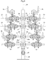
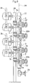
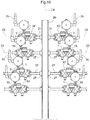
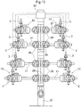
- Figs. 7-10 show one example of such pipe collection device.
- a plurality of horizontally oriented branch pipes (corresponding to a "pipe") 21 are disposed side by side in upside-down distribution and arranged in left-right symmetry relative to a vertically oriented main pipe 22, and respective one ends of these branch pipes 21 are connected to a main pipe 22 as a pipe header.
- the main pipe 22 is disposed under a perpendicular posture (or substantially perpendicular posture) and the branch pipes 21 are disposed side by side and parallel with each other along the perpendicular direction (or substantially perpendicular direction).
- Respective other ends of the branch pipes 21 are connected to a pipe channel 23 for guiding condensate that can mix with steam, e.g. a condensate discharge channel of a steam-using device.
- Each branch pipe 21 is mounted with a connection block 10' having the steam trap 1, the piston valves 2, 19 and the sensor 3.
- the steam trap 1 prevents passage of steam thereof and allows condensate thereof alone to be collected in the main pipe 22. And, condensates collected in this main pipe 22 are returned from the upper end portion of the main pipe 22 via a return channel 24 to e.g. a boiler.
- a blow valve 25 is connected to a lower end portion of the main pipe 22 .
- this blow valve 25 will be opened to open the inside of the main pipe 22 to the atmosphere.
- the main pipe 22 is connected to a strut 26 disposed erect on the floor and the whole device including the branch pipes 21, the connection blocks 10', etc. is supported by the strut 26.
- connection bock 10' is configured to be attachable to the branch pipe 21 even when the block 10' is vertically inverted with its rotation about the front-rear axis p1 perpendicular to the branch pipe 21.
- the connection block 10' to be disposed on the right side (right side facing the plane of the illustration) of the main pipe 22 will be vertically inverted by its rotation about the front-rear axis p1 so as to direct the steam trap 1 to the rear side and direct the piston valves 2, 19 to the front side and the position of the entrance-side pipe connection port 10a and the position of the exit-side pipe connection port 10b are switched over left and right therebetween and under this state, the block 10' is attached to the branch pipe 21.
- connection block 10' and the right side connection block 10' are designed to be used interchangeably in a same mode of attachment.
- the device cost can be lower.
- the upper connection block 10' to be attached to the upper one of the branch pipes 21 adjacent each other vertically is attached to the branch pipe 21 with an offset toward the main pipe 22, relative to the lower connection block 10 to be attached to the lower branch pipe 21.
- the sensor 3 provided in the upper branch pipe 21 (that is, the sensor 3 attached to the substantial upper face of the upper connection block 10') is attached to the upper branch pipe 21 in a layout retracted toward the main pipe 22 in the branch pipe longitudinal direction from the position immediately above.
- the column of the sensors 3 attached to the left side connection blocks 10' and the column of the sensors 3 attached to the right side connection blocks 10' respectively form a part of the respective hypotenuse of an isosceles triangle as seen in a front view.
- attaching operations of these sensors 3 and wire connecting operations to these sensors 3 are made easy and the vertical spacing between the branch pipes 21 is reduced correspondingly, thus forming the entire device compact in its height direction.
- An electric cable pipe 3c of the sensor 3 attached to each connection block 10' is bent rearwards so as to avoid interference with the upper branch pipe 21.
- the sensor 3 detects not only vibration propagating adjacent the steam trap 1 and the piston valve 2, but also the temperature adjacent the steam trap 1 and the piston valve 2. And, detected detection information (temperature, vibration) is transmitted from the communication portion 3c to the analysis device (not shown), so that the analysis device analyzes both the functional state of the steam trap 1 and the functional state of the piston valve 2 in each collection block 10', based upon the detection information transmitted from the respective sensor 3.
- the main pipe 22 is formed by joining a plurality of unit main pipes 22a, each unit main pipe 22a defining a pair of left and right branch pipe connection ports 27 disposed vertically side by side with a predetermined spacing therebetween, and defining also attaching seats 28 for opening/closing valves for opening/closing these branch pipe connection ports 27 individually.
- the main pipe 22 can be used also as a distribution header for distributing fluid to the plurality of branch pipes 21 connected to this main pipe 22. In such case, distribution of fluid to the respective branch pipe 21 is allowed/blocked by opening/closing the opening/closing valve 29 attached to the attaching seat 28 described above.
- the detection information detected by the sensor 3 is transmitted from the communication portion 3b to the analysis device 4 provided separately from the sensor 3, and this analysis device 4 analyzes both a functional state of the steam trap 1 and a functional state of the piston valve 2, based on the detection information transmitted from the sensor 3.
- the disclosure is not limited thereto.
- an analysis device may be provided in the sensor 3, so that the communication portion 3b of the sensor 3 transmits analysis result of the analysis device to a host computer.
- the sensor 3 may be provided with a reporting portion for reporting analysis result provided by the analysis device to the periphery of the sensor 3.
- a common monitoring unit 30 for processing detection information of the respective sensors 3 comprehensively may be provided at an appropriate location, such as at the upper end portion of the main pipe 22. And, this common monitoring unit 30 may be provided with a transmission portion for wirelessly transmitting detection information of each sensor 3 to the analysis device 4, an analysis portion for analyzing a functional state of the steam trap 1 and a functional state of the piston valve 2 in each collection block 10' based on the detection information of each sensor 3, and so on.
- connection block 10' having the entrance-side and exit-side piston valves 2, 19.
- a connection block 10 having only the entrance-side piston valve 2 may be used and instead of the exit-side piston valve 19, an opening/closing valve 29 may be attached to an opening/closing valve attaching seat 28 of the main pipe 22.
- the senor 3 is provided with a vibration sensor and a temperature sensor.
- the disclosure is not limited thereto.
- Other kinds of sensors such as a pressure sensor and a sound sensor, can be provided as long as they are capable of analyzing a functional state of the steam trap and a functional state of the opening/closing valve. Further alternatively, only kind of sensor alone can be provided, or three or more kinds of sensors can be provided.
- connection block 10 the steam trap 1, the piston valve 2 and the sensor 3 together constitute a single unit, or the connection block 10', the steam trap 1, the piston valves 2, 19 and the sensor 3 together constitute a single unit.
- the disclosure is not limited thereto.
- the steam trap 1 or the piston valves 2, 19 may be attached individually to pipes and the sensor 3 may be disposed at an appropriate location in the vicinity of the steam trap 1 and the piston valve 2, so that the functional state of the steam trap and the functional state of the piston valve may be analyzed based on detection information from the sensor 3.
- the entrance-side dual-use attaching port 14a, 14b of the connection block 10, 10' is configured to be communicated to the entrance-side inner channel 12 of the connection block 10, 10', and as the sheath pipe 15 covers the surface of the sensor 3, deterioration of the sensor 3 due to its contact with fluid is prevented.
- the disclosure is not limited thereto.
- the dual-use attaching port 14a, 14b may be configured not to provide communication from the surface of the connection block to the inner channel of the connection block to keep the inserted sensor 3 out of contact with the fluid flowing in the entrance side inner channel 12 of the connection block 10, 10', thereby preventing deterioration of the sensor 3 due to its contact with the fluid.
- the sensor 3 in the case of the left and right switchover between the position of the entrance-side pipe connection port 10a and the position of the exit-side pipe connection port 10b by the upside-down orientation inversion, as for the sensor 3 too, by attaching the sensor 3 to the exit-side dual-use attaching port 17b in the lower face with using, as the sensor attaching portion, the exit-side dual-use attaching port 17b in the lower face portion of the connection block 10' which becomes substantially the upper face portion as result of the upside-down orientation inversion, the sensor 3 to be attached to the dual-use attaching port 17a, 17b too can be connected to the collection block 10' under a same posture.
- the steam trap monitoring system according to this disclosure can be applied to a variety of uses in various fields that require monitoring of a steam trap and an opening/closing valve.
Landscapes
- Engineering & Computer Science (AREA)
- General Engineering & Computer Science (AREA)
- Mechanical Engineering (AREA)
- Pipeline Systems (AREA)
- Indication Of The Valve Opening Or Closing Status (AREA)
- Photoreceptors In Electrophotography (AREA)
Claims (9)
- Système de surveillance de purgeur de vapeur comprenant :un purgeur de vapeur (1) ;un capteur (3) destiné à détecter une ou plusieurs grandeurs physiques :une unité d'analyse (4) destinée à analyser des informations de détection provenant du capteur ;caractérisé en ce quele système de surveillance de purgeur de vapeur comprend en outre une vanne d'ouverture/de fermeture (2, 19) disposée du côté amont du purgeur de vapeur (1) et configurée pour ouvrir/fermer un canal allant vers le purgeur de vapeur (1) etun bloc de raccord (10) présentant ledit purgeur de vapeur (1), ladite vanne d'ouverture/de fermeture (2, 19) et ledit capteur (3) ;où le capteur (3) comprend un capteur de vibrations destiné à détecter des vibrations qui se propagent au voisinage du purgeur de vapeur (1) et de la vanne d'ouverture/de fermeture (2, 19) ; etoù l'unité d'analyse (4) est configurée pour analyser à la fois un état fonctionnel du purgeur de vapeur (1) et un état fonctionnel de la vanne d'ouverture/de fermeture (2, 19), sur la base d'informations de détection provenant de l'unique capteur (3).
- Système de surveillance de purgeur de vapeur selon la revendication 1, où le capteur (3) comprend en outre un capteur de température.
- Système de surveillance de purgeur de vapeur selon la revendication 1 ou 2, dans lequel :le purgeur de vapeur (1) est raccordé à un bloc de raccord (10) présentant un orifice de raccord de tube côté entrée (10a) et un orifice de raccord de tube côté sortie (10b) lesquels s'ouvrent dans des sens opposés l'un par rapport à l'autre, de telle sorte que le purgeur de vapeur (1) communique avec l'orifice de raccord côté entrée (10a) et l'orifice de raccord côté sortie (10b) via un canal intérieur côté entrée (12) et un canal intérieur côté sortie (13) ménagés dans ce bloc de raccord (10) ;la vanne d'ouverture/de fermeture (2, 19) est prévue dans le bloc de raccord (10) de telle sorte à pouvoir ouvrir/fermer le canal intérieur côté entrée (12) ménagé dans le bloc de raccord (10) ;le capteur (3) est prévu dans le bloc de raccord (10) d'un côté amont du purgeur de vapeur (1) ; etle bloc de raccord (10), le purgeur de vapeur (1), la vanne d'ouverture/de fermeture (2, 19) et le capteur (3), de ce fait, constituent ensemble une unique unité.
- Système de surveillance de purgeur de vapeur selon la revendication 3, dans lequel :le bloc de raccord (10) est configuré pour pouvoir être raccordé à un tube (5, 6) devant être installé selon une certaine posture, l'orifice de raccord de tube côté entrée (10a) et l'orifice de raccord de tube côté sortie (10b) étant inversés dans leurs positions passant de gauche à droite et vice versa par une inversion haut-bas par rotation du bloc de raccord (10) autour d'un axe avant-arrière (p1) s'étendant perpendiculairement au tube (5, 6) ;la vanne d'ouverture/de fermeture (2, 19) présente une partie d'actionnement (2a, 19a) disposée au niveau d'une partie de face avant du bloc de raccord (10) ;une partie de fixation de capteur (14) destinée à fixer le capteur (3) par insertion de celui-ci, incluant une partie de fixation de capteur côté face supérieure (14a) prévue dans une partie de face supérieure du bloc de raccord (10) et une partie de fixation de capteur côté face inférieure (14b) prévue dans une partie de face inférieure du bloc de raccord (10), est prévue d'un côté amont du purgeur de vapeur (1) dans le bloc de raccord (10) ; etpour le bloc de raccord (10) qui est fixé au tube (5, 6) sans inversion haut-bas, le capteur (3) est fixé à la partie de fixation de capteur côté face supérieure (14a), tandis que pour le bloc de raccord (10) qui est fixé au tube (5, 6) avec inversion haut-bas, le capteur (3) est fixé à la partie de fixation de capteur côté face inférieure (14b).
- Système de surveillance de purgeur de vapeur selon la revendication 4, dans lequel :la partie de fixation de capteur (14) est configurée pour établir une communication depuis une surface du bloc de raccord (10) vers un canal intérieur (12, 13) du bloc de raccord (10) ; etun couvercle (15) est prévu au niveau d'une partie d'insertion du capteur (3) sur la partie de fixation de capteur (14), de sorte que le capteur (3), lorsqu'il est inséré, reste hors de contact d'un fluide s'écoulant dans le canal intérieur (12, 13) du bloc de raccord (10).
- Système de surveillance de purgeur de vapeur selon la revendication 5, dans lequel :pour le bloc de raccord (10) qui est fixé au tube (5, 6) sans inversion haut-bas, une vanne de purge (16a, 16b) destinée à ouvrir l'intérieur du bloc de raccord (10) vers l'atmosphère est fixée à la partie de fixation de capteur côté face inférieure (14b) ; etpour le bloc de raccord (10) qui est fixé au tube (5, 6) avec inversion haut-bas, la vanne de purge (16a, 16b) est fixée à la partie de fixation de capteur côté face supérieure (14a).
- Système de surveillance de purgeur de vapeur selon la revendication 4, dans lequel :
la partie de fixation de capteur (14) est configurée pour ne pas établir de communication depuis une surface du bloc de raccord (10) vers un canal intérieur (12, 13) du bloc de raccord (10) pour tenir le capteur (3), lorsqu'il est inséré, hors de contact d'un fluide s'écoulant dans le canal intérieur (12, 13) du bloc de raccord (10). - Système de surveillance de purgeur de vapeur selon les revendications 1 et 2 à 7, dans lequel, en plus de la vanne d'ouverture/de fermeture (2, 19), il est prévu une vanne d'ouverture/de fermeture côté sortie (19) disposée d'un côté aval du purgeur de vapeur (1) et configurée pour ouvrir/fermer le canal allant vers le purgeur de vapeur (1).
- Dispositif de collecte de tube dans lequel une pluralité de tubes d'embranchement orientés horizontalement (21) sont raccordés à un tube principal orienté verticalement (22), les tubes d'embranchement (21) étant raccordés en étant parallèles les uns aux autres et répartis verticalement ; le dispositif de collecte de tube comprenant un système de surveillance de purgeur de vapeur selon l'une quelconque des revendications 1 et 2 à 8 qui est appliqué à chacun des tubes d'embranchement (21).
Priority Applications (1)
| Application Number | Priority Date | Filing Date | Title |
|---|---|---|---|
| EP19165154.6A EP3521683B1 (fr) | 2014-10-10 | 2015-07-28 | Unité de purgeur de vapeur |
Applications Claiming Priority (2)
| Application Number | Priority Date | Filing Date | Title |
|---|---|---|---|
| JP2014209135 | 2014-10-10 | ||
| PCT/JP2015/071344 WO2016056292A1 (fr) | 2014-10-10 | 2015-07-28 | Système de surveillance de purgeur de vapeur, dispositif de collecte de tube, et unité de purgeur de vapeur |
Related Child Applications (2)
| Application Number | Title | Priority Date | Filing Date |
|---|---|---|---|
| EP19165154.6A Division EP3521683B1 (fr) | 2014-10-10 | 2015-07-28 | Unité de purgeur de vapeur |
| EP19165154.6A Division-Into EP3521683B1 (fr) | 2014-10-10 | 2015-07-28 | Unité de purgeur de vapeur |
Publications (3)
| Publication Number | Publication Date |
|---|---|
| EP3205923A1 EP3205923A1 (fr) | 2017-08-16 |
| EP3205923A4 EP3205923A4 (fr) | 2018-04-04 |
| EP3205923B1 true EP3205923B1 (fr) | 2019-06-05 |
Family
ID=55652917
Family Applications (2)
| Application Number | Title | Priority Date | Filing Date |
|---|---|---|---|
| EP15849710.7A Active EP3205923B1 (fr) | 2014-10-10 | 2015-07-28 | Système de surveillance de purgeur de vapeur, dispositif de collecte de tube, et unité de purgeur de vapeur |
| EP19165154.6A Active EP3521683B1 (fr) | 2014-10-10 | 2015-07-28 | Unité de purgeur de vapeur |
Family Applications After (1)
| Application Number | Title | Priority Date | Filing Date |
|---|---|---|---|
| EP19165154.6A Active EP3521683B1 (fr) | 2014-10-10 | 2015-07-28 | Unité de purgeur de vapeur |
Country Status (7)
| Country | Link |
|---|---|
| US (1) | US10605408B2 (fr) |
| EP (2) | EP3205923B1 (fr) |
| JP (1) | JP6035436B2 (fr) |
| ES (2) | ES2743907T3 (fr) |
| MY (1) | MY184274A (fr) |
| SG (2) | SG10201907790QA (fr) |
| WO (1) | WO2016056292A1 (fr) |
Families Citing this family (9)
| Publication number | Priority date | Publication date | Assignee | Title |
|---|---|---|---|---|
| US10667023B2 (en) | 2015-05-21 | 2020-05-26 | Armstrong International, Inc. | Steam/hot water monitoring and control system |
| JP6630181B2 (ja) * | 2016-02-16 | 2020-01-15 | 株式会社テイエルブイ | センサ用継手 |
| US12253264B2 (en) * | 2018-02-05 | 2025-03-18 | Alto-Shaam, Inc. | Steam generation and drain system for modular oven |
| US10986843B2 (en) * | 2018-02-05 | 2021-04-27 | Alto-Shaam, Inc. | Combination drain system for multizone oven |
| JP7044628B2 (ja) * | 2018-05-14 | 2022-03-30 | 株式会社テイエルブイ | 流体トラップの詰まり検出システム及び詰まり検出方法 |
| JP6944586B2 (ja) * | 2018-09-27 | 2021-10-06 | 株式会社テイエルブイ | 稼働コスト評価方法および稼働コスト評価プログラム |
| US11460152B2 (en) | 2019-12-10 | 2022-10-04 | Armstrong International, Inc. | Steam trap and valve assembly station |
| WO2022118060A1 (fr) * | 2020-12-04 | 2022-06-09 | 10855561 Canada Inc. | Dispositif, système et procédé de surveillance d'un purgeur de vapeur et de détection d'une défaillance de purgeur de vapeur |
| DE102022101585A1 (de) | 2022-01-24 | 2023-07-27 | Gestra Ag | Regelarmatur mit einer Sensorvorrichtung |
Family Cites Families (21)
| Publication number | Priority date | Publication date | Assignee | Title |
|---|---|---|---|---|
| JPS62212542A (ja) | 1986-03-14 | 1987-09-18 | Tlv Co Ltd | 蒸気漏洩量測定装置 |
| JPH01137391A (ja) | 1987-11-25 | 1989-05-30 | Sanyo Electric Co Ltd | 硬貨処理装置 |
| JPH0735880B2 (ja) | 1988-02-15 | 1995-04-19 | 株式会社テイエルブイ | スチームトラップの無線遠隔作動判定装置 |
| JP2815625B2 (ja) | 1989-09-25 | 1998-10-27 | 財団法人電力中央研究所 | 弁内部リークの検出方法 |
| JP2576793Y2 (ja) * | 1991-03-15 | 1998-07-16 | 東洋エンジニアリング株式会社 | スチームトラップ |
| US5579805A (en) * | 1995-06-09 | 1996-12-03 | Alain; Jean-Claude Cruchet | Valve assembly for a steam-distribution installation in which the condensates are returned |
| GB2302722B (en) | 1995-06-29 | 1999-03-31 | Spirax Sarco Ltd | Equipment comprising a condensate trap |
| JP3924038B2 (ja) | 1997-03-14 | 2007-06-06 | 株式会社テイエルブイ | スチ―ムトラップの作動状態評価方法 |
| US5947145A (en) * | 1997-06-06 | 1999-09-07 | Armstrong International, Inc. | Combination steam trap and flow valve assembly |
| US5881766A (en) * | 1997-06-06 | 1999-03-16 | Armstrong International, Inc. | Manifold and station for mounting steam/condensate responsive devices in a condensate return line |
| JP4094704B2 (ja) * | 1997-07-15 | 2008-06-04 | 株式会社テイエルブイ | トラップ及びバルブの診断装置 |
| JPH1139030A (ja) | 1997-07-15 | 1999-02-12 | Tlv Co Ltd | 設備管理装置及び設備管理プログラムを記録したコンピュータ読み取り可能な記録媒体 |
| US7246036B2 (en) * | 2004-12-08 | 2007-07-17 | Armstrong International, Inc. | Remote monitor for steam traps |
| JP4990204B2 (ja) * | 2008-03-24 | 2012-08-01 | 株式会社神戸製鋼所 | 発電システム及び発電システムの制御方法 |
| GB0807000D0 (en) | 2008-04-17 | 2008-05-21 | Hydralogical Ip Ltd | Improvements in and relating to steam wastage measurement and management |
| JP5674190B2 (ja) | 2009-08-12 | 2015-02-25 | 株式会社テイエルブイ | 弁類の作動状態監視装置 |
| US8573250B1 (en) | 2009-09-01 | 2013-11-05 | Spirax Sarco, Inc. | Steam trap with integrated temperature sensors |
| US20110316707A1 (en) * | 2010-06-28 | 2011-12-29 | Armstrong Global Holdings, Inc. | Remote monitoring system for multiple steam traps |
| JP5715813B2 (ja) * | 2010-12-15 | 2015-05-13 | 株式会社テイエルブイ | 弁類の作動状態検出装置 |
| US9995486B2 (en) * | 2011-12-15 | 2018-06-12 | Honeywell International Inc. | Gas valve with high/low gas pressure detection |
| US9863836B2 (en) * | 2011-12-30 | 2018-01-09 | Spirax-Sarco Limited | Monitoring apparatus for a steam plant and a method of operating such an apparatus |
-
2015
- 2015-07-28 EP EP15849710.7A patent/EP3205923B1/fr active Active
- 2015-07-28 ES ES15849710T patent/ES2743907T3/es active Active
- 2015-07-28 ES ES19165154T patent/ES2870136T3/es active Active
- 2015-07-28 WO PCT/JP2015/071344 patent/WO2016056292A1/fr not_active Ceased
- 2015-07-28 US US15/517,743 patent/US10605408B2/en active Active
- 2015-07-28 EP EP19165154.6A patent/EP3521683B1/fr active Active
- 2015-07-28 SG SG10201907790Q patent/SG10201907790QA/en unknown
- 2015-07-28 SG SG11201702876SA patent/SG11201702876SA/en unknown
- 2015-07-28 JP JP2015562990A patent/JP6035436B2/ja active Active
- 2015-07-28 MY MYPI2017701221A patent/MY184274A/en unknown
Non-Patent Citations (1)
| Title |
|---|
| None * |
Also Published As
| Publication number | Publication date |
|---|---|
| JPWO2016056292A1 (ja) | 2017-04-27 |
| SG10201907790QA (en) | 2019-10-30 |
| EP3205923A1 (fr) | 2017-08-16 |
| EP3521683A1 (fr) | 2019-08-07 |
| WO2016056292A1 (fr) | 2016-04-14 |
| JP6035436B2 (ja) | 2016-11-30 |
| EP3205923A4 (fr) | 2018-04-04 |
| MY184274A (en) | 2021-03-30 |
| SG11201702876SA (en) | 2017-05-30 |
| EP3521683B1 (fr) | 2021-02-17 |
| ES2870136T3 (es) | 2021-10-26 |
| ES2743907T3 (es) | 2020-02-21 |
| US20170299117A1 (en) | 2017-10-19 |
| US10605408B2 (en) | 2020-03-31 |
Similar Documents
| Publication | Publication Date | Title |
|---|---|---|
| EP3205923B1 (fr) | Système de surveillance de purgeur de vapeur, dispositif de collecte de tube, et unité de purgeur de vapeur | |
| AU2017363262B2 (en) | Combination of isolation valve and check valve with integrated flow rate, pressure and/or temperature measurement and field configurability | |
| US7886592B2 (en) | Flow sensor | |
| JP2020521988A (ja) | トランスミッタ用自己排水マウントヘッド | |
| JP5923225B2 (ja) | 配管集合装置 | |
| US10317003B2 (en) | Double block and bleed system for an orifice fitting | |
| US20140103274A1 (en) | Apparatus and method for installing or removing a cable | |
| US20180119845A1 (en) | Sensor connection structure | |
| KR20190133518A (ko) | 누출 감지장치 | |
| KR102575886B1 (ko) | 고온 고압용 밸브의 미세누설 감지센서모듈 | |
| CN108844623B (zh) | 一种高压压气机转子叶片振动测试系统 | |
| US20150377674A1 (en) | Coriolis Mass Flowmeter | |
| IT202300007374A1 (it) | Gruppo valvola perfezionato. | |
| EP3985360B1 (fr) | Mesure du débit à l'aide de tubes de pitot multiples et d'unités de détection multiples | |
| US20160184749A1 (en) | Device for locking a filter in a conduit | |
| JP2009532667A (ja) | 流体分配アセンブリおよびその使用 | |
| CN106196736A (zh) | 制冷机 | |
| US20210190636A1 (en) | Control cabinet | |
| KR101690784B1 (ko) | 측정모듈이 구비된 가스 파이프용 실시간 모니터링 시스템 | |
| KR20160025177A (ko) | 보일러 파이프라인의 압력측정 구조물 | |
| KR20130062761A (ko) | 해양구조물의 파이프 누설 감지장치 |
Legal Events
| Date | Code | Title | Description |
|---|---|---|---|
| STAA | Information on the status of an ep patent application or granted ep patent |
Free format text: STATUS: THE INTERNATIONAL PUBLICATION HAS BEEN MADE |
|
| PUAI | Public reference made under article 153(3) epc to a published international application that has entered the european phase |
Free format text: ORIGINAL CODE: 0009012 |
|
| STAA | Information on the status of an ep patent application or granted ep patent |
Free format text: STATUS: REQUEST FOR EXAMINATION WAS MADE |
|
| 17P | Request for examination filed |
Effective date: 20170413 |
|
| AK | Designated contracting states |
Kind code of ref document: A1 Designated state(s): AL AT BE BG CH CY CZ DE DK EE ES FI FR GB GR HR HU IE IS IT LI LT LU LV MC MK MT NL NO PL PT RO RS SE SI SK SM TR |
|
| AX | Request for extension of the european patent |
Extension state: BA ME |
|
| DAV | Request for validation of the european patent (deleted) | ||
| DAX | Request for extension of the european patent (deleted) | ||
| A4 | Supplementary search report drawn up and despatched |
Effective date: 20180302 |
|
| RIC1 | Information provided on ipc code assigned before grant |
Ipc: F16T 1/48 20060101AFI20180226BHEP Ipc: F16T 1/02 20060101ALI20180226BHEP |
|
| GRAP | Despatch of communication of intention to grant a patent |
Free format text: ORIGINAL CODE: EPIDOSNIGR1 |
|
| STAA | Information on the status of an ep patent application or granted ep patent |
Free format text: STATUS: GRANT OF PATENT IS INTENDED |
|
| RIC1 | Information provided on ipc code assigned before grant |
Ipc: F16T 1/02 20060101ALI20190111BHEP Ipc: F16T 1/48 20060101AFI20190111BHEP |
|
| INTG | Intention to grant announced |
Effective date: 20190207 |
|
| GRAS | Grant fee paid |
Free format text: ORIGINAL CODE: EPIDOSNIGR3 |
|
| GRAA | (expected) grant |
Free format text: ORIGINAL CODE: 0009210 |
|
| STAA | Information on the status of an ep patent application or granted ep patent |
Free format text: STATUS: THE PATENT HAS BEEN GRANTED |
|
| AK | Designated contracting states |
Kind code of ref document: B1 Designated state(s): AL AT BE BG CH CY CZ DE DK EE ES FI FR GB GR HR HU IE IS IT LI LT LU LV MC MK MT NL NO PL PT RO RS SE SI SK SM TR |
|
| REG | Reference to a national code |
Ref country code: GB Ref legal event code: FG4D |
|
| REG | Reference to a national code |
Ref country code: CH Ref legal event code: EP |
|
| REG | Reference to a national code |
Ref country code: AT Ref legal event code: REF Ref document number: 1140356 Country of ref document: AT Kind code of ref document: T Effective date: 20190615 |
|
| REG | Reference to a national code |
Ref country code: DE Ref legal event code: R096 Ref document number: 602015031558 Country of ref document: DE |
|
| REG | Reference to a national code |
Ref country code: IE Ref legal event code: FG4D |
|
| REG | Reference to a national code |
Ref country code: CH Ref legal event code: NV Representative=s name: DENNEMEYER AG, CH |
|
| REG | Reference to a national code |
Ref country code: NL Ref legal event code: FP |
|
| REG | Reference to a national code |
Ref country code: LT Ref legal event code: MG4D |
|
| PG25 | Lapsed in a contracting state [announced via postgrant information from national office to epo] |
Ref country code: FI Free format text: LAPSE BECAUSE OF FAILURE TO SUBMIT A TRANSLATION OF THE DESCRIPTION OR TO PAY THE FEE WITHIN THE PRESCRIBED TIME-LIMIT Effective date: 20190605 Ref country code: NO Free format text: LAPSE BECAUSE OF FAILURE TO SUBMIT A TRANSLATION OF THE DESCRIPTION OR TO PAY THE FEE WITHIN THE PRESCRIBED TIME-LIMIT Effective date: 20190905 Ref country code: LT Free format text: LAPSE BECAUSE OF FAILURE TO SUBMIT A TRANSLATION OF THE DESCRIPTION OR TO PAY THE FEE WITHIN THE PRESCRIBED TIME-LIMIT Effective date: 20190605 Ref country code: HR Free format text: LAPSE BECAUSE OF FAILURE TO SUBMIT A TRANSLATION OF THE DESCRIPTION OR TO PAY THE FEE WITHIN THE PRESCRIBED TIME-LIMIT Effective date: 20190605 Ref country code: SE Free format text: LAPSE BECAUSE OF FAILURE TO SUBMIT A TRANSLATION OF THE DESCRIPTION OR TO PAY THE FEE WITHIN THE PRESCRIBED TIME-LIMIT Effective date: 20190605 Ref country code: AL Free format text: LAPSE BECAUSE OF FAILURE TO SUBMIT A TRANSLATION OF THE DESCRIPTION OR TO PAY THE FEE WITHIN THE PRESCRIBED TIME-LIMIT Effective date: 20190605 |
|
| PG25 | Lapsed in a contracting state [announced via postgrant information from national office to epo] |
Ref country code: BG Free format text: LAPSE BECAUSE OF FAILURE TO SUBMIT A TRANSLATION OF THE DESCRIPTION OR TO PAY THE FEE WITHIN THE PRESCRIBED TIME-LIMIT Effective date: 20190905 Ref country code: LV Free format text: LAPSE BECAUSE OF FAILURE TO SUBMIT A TRANSLATION OF THE DESCRIPTION OR TO PAY THE FEE WITHIN THE PRESCRIBED TIME-LIMIT Effective date: 20190605 Ref country code: GR Free format text: LAPSE BECAUSE OF FAILURE TO SUBMIT A TRANSLATION OF THE DESCRIPTION OR TO PAY THE FEE WITHIN THE PRESCRIBED TIME-LIMIT Effective date: 20190906 Ref country code: RS Free format text: LAPSE BECAUSE OF FAILURE TO SUBMIT A TRANSLATION OF THE DESCRIPTION OR TO PAY THE FEE WITHIN THE PRESCRIBED TIME-LIMIT Effective date: 20190605 |
|
| REG | Reference to a national code |
Ref country code: AT Ref legal event code: MK05 Ref document number: 1140356 Country of ref document: AT Kind code of ref document: T Effective date: 20190605 |
|
| PG25 | Lapsed in a contracting state [announced via postgrant information from national office to epo] |
Ref country code: AT Free format text: LAPSE BECAUSE OF FAILURE TO SUBMIT A TRANSLATION OF THE DESCRIPTION OR TO PAY THE FEE WITHIN THE PRESCRIBED TIME-LIMIT Effective date: 20190605 Ref country code: EE Free format text: LAPSE BECAUSE OF FAILURE TO SUBMIT A TRANSLATION OF THE DESCRIPTION OR TO PAY THE FEE WITHIN THE PRESCRIBED TIME-LIMIT Effective date: 20190605 Ref country code: CZ Free format text: LAPSE BECAUSE OF FAILURE TO SUBMIT A TRANSLATION OF THE DESCRIPTION OR TO PAY THE FEE WITHIN THE PRESCRIBED TIME-LIMIT Effective date: 20190605 Ref country code: RO Free format text: LAPSE BECAUSE OF FAILURE TO SUBMIT A TRANSLATION OF THE DESCRIPTION OR TO PAY THE FEE WITHIN THE PRESCRIBED TIME-LIMIT Effective date: 20190605 Ref country code: SK Free format text: LAPSE BECAUSE OF FAILURE TO SUBMIT A TRANSLATION OF THE DESCRIPTION OR TO PAY THE FEE WITHIN THE PRESCRIBED TIME-LIMIT Effective date: 20190605 Ref country code: PT Free format text: LAPSE BECAUSE OF FAILURE TO SUBMIT A TRANSLATION OF THE DESCRIPTION OR TO PAY THE FEE WITHIN THE PRESCRIBED TIME-LIMIT Effective date: 20191007 |
|
| REG | Reference to a national code |
Ref country code: ES Ref legal event code: FG2A Ref document number: 2743907 Country of ref document: ES Kind code of ref document: T3 Effective date: 20200221 |
|
| PG25 | Lapsed in a contracting state [announced via postgrant information from national office to epo] |
Ref country code: SM Free format text: LAPSE BECAUSE OF FAILURE TO SUBMIT A TRANSLATION OF THE DESCRIPTION OR TO PAY THE FEE WITHIN THE PRESCRIBED TIME-LIMIT Effective date: 20190605 Ref country code: IS Free format text: LAPSE BECAUSE OF FAILURE TO SUBMIT A TRANSLATION OF THE DESCRIPTION OR TO PAY THE FEE WITHIN THE PRESCRIBED TIME-LIMIT Effective date: 20191005 |
|
| REG | Reference to a national code |
Ref country code: DE Ref legal event code: R097 Ref document number: 602015031558 Country of ref document: DE |
|
| PG25 | Lapsed in a contracting state [announced via postgrant information from national office to epo] |
Ref country code: MC Free format text: LAPSE BECAUSE OF FAILURE TO SUBMIT A TRANSLATION OF THE DESCRIPTION OR TO PAY THE FEE WITHIN THE PRESCRIBED TIME-LIMIT Effective date: 20190605 |
|
| PLBE | No opposition filed within time limit |
Free format text: ORIGINAL CODE: 0009261 |
|
| STAA | Information on the status of an ep patent application or granted ep patent |
Free format text: STATUS: NO OPPOSITION FILED WITHIN TIME LIMIT |
|
| PG25 | Lapsed in a contracting state [announced via postgrant information from national office to epo] |
Ref country code: DK Free format text: LAPSE BECAUSE OF FAILURE TO SUBMIT A TRANSLATION OF THE DESCRIPTION OR TO PAY THE FEE WITHIN THE PRESCRIBED TIME-LIMIT Effective date: 20190605 Ref country code: PL Free format text: LAPSE BECAUSE OF FAILURE TO SUBMIT A TRANSLATION OF THE DESCRIPTION OR TO PAY THE FEE WITHIN THE PRESCRIBED TIME-LIMIT Effective date: 20190605 |
|
| 26N | No opposition filed |
Effective date: 20200306 |
|
| PG25 | Lapsed in a contracting state [announced via postgrant information from national office to epo] |
Ref country code: SI Free format text: LAPSE BECAUSE OF FAILURE TO SUBMIT A TRANSLATION OF THE DESCRIPTION OR TO PAY THE FEE WITHIN THE PRESCRIBED TIME-LIMIT Effective date: 20190605 Ref country code: LU Free format text: LAPSE BECAUSE OF NON-PAYMENT OF DUE FEES Effective date: 20190728 |
|
| PG25 | Lapsed in a contracting state [announced via postgrant information from national office to epo] |
Ref country code: IE Free format text: LAPSE BECAUSE OF NON-PAYMENT OF DUE FEES Effective date: 20190728 |
|
| PG25 | Lapsed in a contracting state [announced via postgrant information from national office to epo] |
Ref country code: CY Free format text: LAPSE BECAUSE OF FAILURE TO SUBMIT A TRANSLATION OF THE DESCRIPTION OR TO PAY THE FEE WITHIN THE PRESCRIBED TIME-LIMIT Effective date: 20190605 |
|
| PG25 | Lapsed in a contracting state [announced via postgrant information from national office to epo] |
Ref country code: HU Free format text: LAPSE BECAUSE OF FAILURE TO SUBMIT A TRANSLATION OF THE DESCRIPTION OR TO PAY THE FEE WITHIN THE PRESCRIBED TIME-LIMIT; INVALID AB INITIO Effective date: 20150728 Ref country code: MT Free format text: LAPSE BECAUSE OF FAILURE TO SUBMIT A TRANSLATION OF THE DESCRIPTION OR TO PAY THE FEE WITHIN THE PRESCRIBED TIME-LIMIT Effective date: 20190605 |
|
| PG25 | Lapsed in a contracting state [announced via postgrant information from national office to epo] |
Ref country code: MK Free format text: LAPSE BECAUSE OF FAILURE TO SUBMIT A TRANSLATION OF THE DESCRIPTION OR TO PAY THE FEE WITHIN THE PRESCRIBED TIME-LIMIT Effective date: 20190605 |
|
| PGFP | Annual fee paid to national office [announced via postgrant information from national office to epo] |
Ref country code: NL Payment date: 20250721 Year of fee payment: 11 |
|
| PGFP | Annual fee paid to national office [announced via postgrant information from national office to epo] |
Ref country code: ES Payment date: 20250826 Year of fee payment: 11 |
|
| PGFP | Annual fee paid to national office [announced via postgrant information from national office to epo] |
Ref country code: DE Payment date: 20250722 Year of fee payment: 11 |
|
| PGFP | Annual fee paid to national office [announced via postgrant information from national office to epo] |
Ref country code: IT Payment date: 20250724 Year of fee payment: 11 Ref country code: TR Payment date: 20250722 Year of fee payment: 11 |
|
| PGFP | Annual fee paid to national office [announced via postgrant information from national office to epo] |
Ref country code: BE Payment date: 20250718 Year of fee payment: 11 Ref country code: GB Payment date: 20250722 Year of fee payment: 11 |
|
| PGFP | Annual fee paid to national office [announced via postgrant information from national office to epo] |
Ref country code: FR Payment date: 20250725 Year of fee payment: 11 |
|
| PGFP | Annual fee paid to national office [announced via postgrant information from national office to epo] |
Ref country code: CH Payment date: 20250801 Year of fee payment: 11 |