EP3205961A1 - Dispositif d'appareil ménager - Google Patents
Dispositif d'appareil ménager Download PDFInfo
- Publication number
- EP3205961A1 EP3205961A1 EP17152596.7A EP17152596A EP3205961A1 EP 3205961 A1 EP3205961 A1 EP 3205961A1 EP 17152596 A EP17152596 A EP 17152596A EP 3205961 A1 EP3205961 A1 EP 3205961A1
- Authority
- EP
- European Patent Office
- Prior art keywords
- storage unit
- appliance device
- holding
- pull
- advantageously
- Prior art date
- Legal status (The legal status is an assumption and is not a legal conclusion. Google has not performed a legal analysis and makes no representation as to the accuracy of the status listed.)
- Withdrawn
Links
Images


Classifications
-
- F—MECHANICAL ENGINEERING; LIGHTING; HEATING; WEAPONS; BLASTING
- F25—REFRIGERATION OR COOLING; COMBINED HEATING AND REFRIGERATION SYSTEMS; HEAT PUMP SYSTEMS; MANUFACTURE OR STORAGE OF ICE; LIQUEFACTION SOLIDIFICATION OF GASES
- F25D—REFRIGERATORS; COLD ROOMS; ICE-BOXES; COOLING OR FREEZING APPARATUS NOT OTHERWISE PROVIDED FOR
- F25D23/00—General constructional features
- F25D23/06—Walls
- F25D23/065—Details
- F25D23/067—Supporting elements
-
- A—HUMAN NECESSITIES
- A47—FURNITURE; DOMESTIC ARTICLES OR APPLIANCES; COFFEE MILLS; SPICE MILLS; SUCTION CLEANERS IN GENERAL
- A47B—TABLES; DESKS; OFFICE FURNITURE; CABINETS; DRAWERS; GENERAL DETAILS OF FURNITURE
- A47B57/00—Cabinets, racks or shelf units, characterised by features for adjusting shelves or partitions
- A47B57/06—Cabinets, racks or shelf units, characterised by features for adjusting shelves or partitions with means for adjusting the height of the shelves
- A47B57/16—Cabinets, racks or shelf units, characterised by features for adjusting shelves or partitions with means for adjusting the height of the shelves consisting of hooks coacting with openings
-
- A—HUMAN NECESSITIES
- A47—FURNITURE; DOMESTIC ARTICLES OR APPLIANCES; COFFEE MILLS; SPICE MILLS; SUCTION CLEANERS IN GENERAL
- A47B—TABLES; DESKS; OFFICE FURNITURE; CABINETS; DRAWERS; GENERAL DETAILS OF FURNITURE
- A47B96/00—Details of cabinets, racks or shelf units not covered by a single one of groups A47B43/00 - A47B95/00; General details of furniture
- A47B96/02—Shelves
- A47B96/025—Shelves with moving elements, e.g. movable extensions or link elements
-
- A—HUMAN NECESSITIES
- A47—FURNITURE; DOMESTIC ARTICLES OR APPLIANCES; COFFEE MILLS; SPICE MILLS; SUCTION CLEANERS IN GENERAL
- A47B—TABLES; DESKS; OFFICE FURNITURE; CABINETS; DRAWERS; GENERAL DETAILS OF FURNITURE
- A47B96/00—Details of cabinets, racks or shelf units not covered by a single one of groups A47B43/00 - A47B95/00; General details of furniture
- A47B96/02—Shelves
- A47B96/027—Cantilever shelves
-
- F—MECHANICAL ENGINEERING; LIGHTING; HEATING; WEAPONS; BLASTING
- F25—REFRIGERATION OR COOLING; COMBINED HEATING AND REFRIGERATION SYSTEMS; HEAT PUMP SYSTEMS; MANUFACTURE OR STORAGE OF ICE; LIQUEFACTION SOLIDIFICATION OF GASES
- F25D—REFRIGERATORS; COLD ROOMS; ICE-BOXES; COOLING OR FREEZING APPARATUS NOT OTHERWISE PROVIDED FOR
- F25D25/00—Charging, supporting, and discharging the articles to be cooled
- F25D25/02—Charging, supporting, and discharging the articles to be cooled by shelves
- F25D25/024—Slidable shelves
Definitions
- the invention relates to a household appliance device according to the preamble of claim 1.
- Refrigerators with holding devices for storage shelves are already known from the prior art, which are arranged on a rear wall of a refrigerator body.
- the object of the invention is in particular to provide a generic device with improved properties in terms of ease of use.
- the object is achieved by the characterizing features of claim 1, while advantageous embodiments and refinements of the invention can be taken from the dependent claims.
- the invention is based on a household appliance device, in particular a household refrigeration device, with at least one appliance body which has at least one rear wall and defines an access opening, with at least one storage unit and with at least one holding unit arranged in a region of the rear wall, which stores the storage unit in at least one State holds.
- the storage unit has at least one pull-out element which can be pulled out towards the access opening.
- a "household appliance device” is to be understood as meaning, in particular, at least one part, in particular a subassembly, of a domestic appliance, in particular a household refrigerating appliance.
- the household appliance device may also comprise the entire domestic appliance, in particular the entire domestic refrigeration appliance.
- the household appliance is designed as a refrigerator and / or freezer, in particular as a refrigerator, freezer, freezer, freezer,dochierigefrierkombination and / or wine storage cabinet.
- the household appliance device comprises at least one appliance body, which in particular delimits and / or defines an interior, preferably at least one utility space, and in particular has the access opening.
- a unit can be understood which, in at least one assembled state, forms a part, in particular a major part, of an outer boundary, in particular of a housing, advantageously of a domestic appliance, preferably of a domestic refrigerating appliance, and which, in the assembled state, forms a part, in particular a large part, an outer boundary of at least one useful space, preferably a cold room and particularly preferably a cold room and / or a freezer compartment defined.
- the device body encloses the interior space on an upper side, on an underside, on two opposite sides, as well as on the rear side, wherein in particular a front side remains open.
- a door arranged on the front side is designed differently from the device body.
- An "access opening” should be understood, in particular, to mean a region defined by the device body, which must be penetrated to reach the useful space, in particular a rectangular opening, preferably in the front of the device body, particularly preferably with a surface that can accommodate objects such as especially food allowed in the interior.
- a “storage unit” is to be understood in particular as a unit which is provided for parking or depositing objects, in particular food.
- the storage unit may be formed at least substantially plate-like and / or have at least one at least substantially plate-like trained element, and in particular for parking or storing objects, in particular food, be provided in a plate-like area.
- a "plate-like” object is to be understood in particular as meaning an object which has a considerably greater extent along a first spatial direction and along a second spatial direction than along a third spatial direction, preferably one at least a factor of 5, advantageously one at least a factor of 10 and particularly advantageously a greater extension by at least a factor of 20, wherein the three spatial directions should be perpendicular to each other in pairs.
- an "extension in one direction" of an element is to be understood as meaning, in particular, a maximum distance between two points of a vertical projection of the element onto a plane that is parallel to the direction.
- By “intended” is intended to be understood in particular specially designed and / or equipped. Under which an object is intended for a specific function, In particular, it should be understood that the object fulfills and / or executes this particular function in at least one application and / or operating state.
- the point farthest from the rear wall on the holding unit is at most 25 cm, preferably at most 15 cm, advantageously at most 10 cm, particularly advantageously at most, that the holding unit is arranged "in a region of the rear wall" 5 cm, located from at least one point on the back wall.
- a main extension plane of the holding unit runs at least substantially parallel to a main extension plane of the rear wall.
- a "main extension plane" of an object should be understood to mean, in particular, a plane which is parallel to a largest side surface of a smallest imaginary cuboid which just completely surrounds the object, and in particular runs through the center of the cuboid.
- At least substantially parallel should be understood here in particular an alignment of a direction relative to a reference direction, in particular in a plane, wherein the direction relative to the reference direction a deviation in particular less than 8 °, advantageously less than 5 ° and particularly advantageously smaller than 2 °.
- the pull-out element is displaceable in a direction parallel to a surface normal of the main extension plane of the rear wall, that the pull-out element can be pulled out "towards the access opening".
- the inventive design can be achieved in particular an increased ease of use. Further advantageously, facilitated access to objects parked in a rear area of a household appliance interior can be made possible. Furthermore, advantageously storage units can be easily cleaned. In particular, differently configured storage units, such as in particular storage plates, bottle trays, or goods containers, can be arranged extensible in a household appliance. Furthermore, storage units can be arranged in a household appliance body with predominantly flat inner walls, whereby in particular the walls are easy to clean. In addition, a modern attractive design is advantageously achieved.
- the storage unit has at least one base element, which is mounted in the mounted state on the holding unit.
- the pullout element is slidably mounted on the base member.
- the pull-out element is captively connected to the base element and / or extendable up to a stop point.
- the base element has a frame element.
- a projection of the base element on a main extension plane of the base element has at least substantially a rectangular outline.
- the frame element may have a lower storage tray.
- the lower storage tray is at least partially covered by the pull-out element in a completely inserted state.
- the lower storage tray is at least partially released in a fully extended state of the extract element.
- a "storage shelf” is to be understood in particular as a plate-like element which is provided for parking or depositing objects, in particular food.
- the base element can be made of plastic for at least a major part.
- the base element is made of at least a large part of a metal, for example of aluminum and / or stainless steel and / or steel.
- the base element is integrally formed.
- differently configured storage units may have at least substantially identical base elements.
- one piece should be understood in particular at least materially connected connected, for example, by a welding process, a gluing process, a Anspritzrea and / or another, the skilled person appear useful process, and / or advantageously formed in one piece, such as by a Manufacture from a casting and / or by a production in a one- or multi-component injection molding process and advantageously from a single blank.
- At least substantially identical objects is to be understood in this context, in particular, that the objects are constructed in such a way that they can perform a common function and differ in their construction not or only by individual elements that are immaterial to the common function .
- the term "at least a large part” should be understood to mean in particular at least 55%, advantageously at least 65%, preferably at least 75%, particularly preferably at least 85% and particularly advantageously at least 95%. This can advantageously secure fixing of the storage unit be achieved. Furthermore, this can be achieved by a variable fastening system.
- the holding unit has at least one holding profile with at least one holding recess into which at least a part of the base element can be inserted.
- the retaining profile may in particular have an at least substantially constant cross section.
- An at least substantially constant cross-section of an object should be understood in particular to mean that for any first cross-section of the object along at least one direction and an arbitrary second cross-section of the object along the direction, a minimum surface area of a differential area formed when the cross-sections are superimposed is a maximum of 20%, advantageously at most 10%, more preferably at most 5% of the surface area of the larger of the two cross sections.
- the holding profile may be a producible by extrusion element.
- the holding profile is advantageously a continuous casting profile.
- the retaining profile is a producible from a sheet metal element.
- the retaining profile extends over at least a majority of a width of the interior of the device body.
- the insertable into the holding recess part of the base member has a width which corresponds at least substantially to an extension of the holding profile in the direction of a main extension direction of the holding profile.
- the base element preferably has a hook profile element, which in a mounted state is positively connected to at least one part of the retaining profile.
- a "main direction of extension" of an object should be understood to mean, in particular, a direction which runs parallel to a longest edge of a smallest imaginary cuboid which just completely encloses the object.
- At least a part of the base element in the holding recess is "plugged", should be understood in particular that in an inserted state, at least a portion of the base member is positively connected to at least a portion of the retaining profile.
- at least part of the base element can be inserted without tools into the holding recess.
- at least a part of the base element can be inserted into the holding recess relative to the holding unit by at least one linear movement and / or at least one tilting movement of the depositing unit. This can advantageously be achieved a secure holding the storage unit.
- a simple installation and / or removal of the storage unit can advantageously be made possible.
- the base element has at least one support element which, in an assembled state, counteracts a torque occurring when the storage unit is held.
- the support element is integrally connected to the base element.
- the support element is provided to dissipate forces occurring at a holding at least a large part in the holding profile.
- the support element is designed in the manner of a console support.
- a lateral projection of the support element at least substantially in the form of a right triangle, wherein in particular a hypotenuse obliquely, a shorter catheter parallel, and a longer catheter perpendicular to a surface normal of a main extension plane of the storage unit.
- the support element bears against the retaining profile on one side of the shorter catheter.
- the base element has two support elements, which are arranged on opposite sides of the base element.
- the base element is designed in the manner of a frame whose front side faces an operator whose rear side bears against the retaining profile, and whose sides are formed by a respective support element. In this way, in particular, an advantageous statics can be achieved. Furthermore, this can advantageously be achieved a secure holding the storage unit.
- a main extension direction of the holding recess extends in an at least substantially horizontal direction and at least substantially parallel to a main extension direction of the holding profile.
- the holding profile forms a holding recess with an insertion pocket, which has a substantially constant cross-section and extends over at least a majority of the extension of the holding profile in the direction of the main extension direction of the holding profile, and in which at least one extension of the base member is positively inserted.
- the term "at least substantially in the horizontal direction” should be understood to mean, in particular, an orientation relative to a surface normal of a subsoil, in particular a terrestrial surface, in particular in a normal operating state of the household appliance device, wherein the direction relative to a direction perpendicular to the surface normal of the subsoil is a deviation in particular less than 8 °, advantageously less than 5 ° and particularly advantageously less than 2 °.
- the term "at least substantially parallel” is intended here to mean, in particular, an alignment of a Direction relative to a reference direction, in particular in a plane to be understood, the direction relative to the reference direction has a deviation in particular less than 8 °, advantageously less than 5 ° and particularly advantageously less than 2 °.
- the storage unit has at least a first slide rail element, which is connected to the base element, and at least one second slide rail element which is connected to the pull-out element and displaceably mounted relative to the first slide rail element.
- the first slide rail element can be integrally connected to the base element.
- the slide rail element is arranged in at least one recess and / or a recess and / or a recess of the base element.
- the second slide rail element may particularly preferably be connected in one piece with the pull-out element.
- a main extension direction of the first slide rail element runs parallel to a surface normal of the rear wall and parallel to a main extension direction of the second slide rail element.
- the second slide rail element in at least one mounted state, is displaceably mounted relative to the first slide rail element in a direction parallel to the surface normal of the rear wall.
- the storage unit preferably has, on two opposite sides, in each case a first slide rail element and in each case a second slide rail element which displaceably mount the pull-out unit relative to the base unit.
- the first slide rail element and / or the second slide rail element has a stopper element which limits a maximum displaceability of the second slide rail element relative to the first slide rail element.
- a maximum coefficient of static friction between the slide rail elements is 0.5, advantageously 0.3 and particularly advantageously 0.2.
- a maximum sliding friction coefficient between the slide rail elements is 0.3, advantageously 0.2 and particularly advantageously 0.1.
- at least one of the slide rail elements has a plain bearing, in particular plastic plain bearings.
- at least one of the slide rail elements to have at least one roller which rolls over another slide rail element when the pull-out element is pulled out and / or inserted.
- the first slide rail element and / or the second slide rail element made of plastic, in particular polyoxymethylene. In particular, this can advantageously be made possible with minimal effort. Furthermore advantageously, a secure guidance of extendable parts can be ensured.
- the pull-out element has at least one storage shelf.
- the storage tray is at least partially transparent and / or at least partially translucent.
- at least partially transparent is meant in particular at least partially transparent to visible light, in particular a transparency of at least 5%, preferably of at least 10%, more preferably of at least 20%, advantageously of at least 50% and particularly advantageously of at least 80% %, wherein a transmitted light is at least substantially parallel to an incident light.
- the storage tray is advantageously made of glass. But it is also conceivable that the storage tray is formed of a plastic. As a result, an area for a safe setting up of food can advantageously be provided. Furthermore advantageously, a user comfort can be increased thereby.
- a projection of the pull-out element onto a main extension plane of the storage unit at least substantially corresponds to a projection of the storage unit onto the main extension plane of the storage unit.
- the projection of the storage tray of the pull-out element on a main extension plane of the storage unit corresponds at least substantially to a projection of the storage unit onto the main extension plane of the storage unit.
- the pull-out element has at least one handle element.
- the grip element is arranged on a front side of the pull-out element.
- the handle member integrally connected to the pullout element.
- the handle element is designed as a handle bar with a substantially constant rectangular cross-section.
- the grip element extends over at least a major part of the width of the pullout element.
- the handle element faces the access opening in an assembled state.
- the storage unit is provided for a tool-free installation and / or disassembly to / from the holding unit.
- the storage unit is designed to be mountable and / or removable by at least one linear movement and / or at least one tilting movement of the storage unit relative to the holding unit.
- the household appliance device should not be limited to the application and embodiment described above.
- the household appliance device may have a number deviating from a number of individual elements, components and units mentioned herein.
- FIG. 1 shows a trained as a refrigerator home appliance 38a with a household appliance device in a perspective view.
- the household appliance device has a device body 10a with a rear wall 12a defining an interior 40a and an access opening 14a. Furthermore, the household appliance device has storage units 16a which are held in the region of the rear wall 12a.
- FIG. 2 shows a holding unit 18a of the household appliance device, which is arranged in the region of the rear wall 12a of the device body 10a of the household appliance device, in a perspective view.
- the holding unit 18a has a plurality of holding profiles 24a, each with a holding recess 26a.
- the retaining profiles 24a are fastened to vertical rail elements 42a, 44a, 46a, 48a.
- the rail elements 42a, 44a, 46a, 48a are connected to the device body 10a (not shown) and thus can dissipate any holding forces occurring to the device body 10a.
- a main extension direction of the holding recess 26a extends in an at least substantially horizontal direction and at least substantially parallel to a main extension direction of the corresponding holding profile 24a.
- the length of the holding recess 26a corresponds at least substantially to the length of the holding profile 24a.
- the length of the retaining profile 24a extends over at least a majority of the width of the rear wall 12a.
- the holding profiles 24a are aligned parallel to one another and arranged one above the other.
- FIG. 3 shows a bezel 50a of the household appliance device, which can be attached to a front side of the holding unit 18a and recesses 52a, through which the retaining recesses 26a are accessible.
- the bezel 50a covers a majority of the holding unit 18a in the direction of the access opening 14a and forms a rear wall element (not shown) in the inner space 40a of the appliance body 10a.
- the panel 50a protects the holding unit 18a, for example, against contamination.
- a use of the panel 50a is purely optional, ie the storage unit can be mounted on the holding unit even in the absence of the panel 50a.
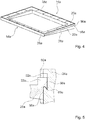
- FIG. 4 shows a storage unit 16a of the household appliance device in a perspective view.
- the storage unit 16a has a base element 22a and an extension element 20a, which is mounted extendable relative to the base element 22a in the direction of a front side 54a of the storage unit 16a (see also FIG FIG. 6 ).
- a projection of the pull-out element 20a onto a main extension plane of the storage unit 16a corresponds at least substantially to a projection of the storage unit 16a onto the main extension plane of the storage unit 16a.
- the base element 22a has a hook profile 56a, which can be inserted into the retaining recess 26a of the retaining profile 24a of the retaining unit 18a, so that the base element 22a can be mounted on the retaining unit 18a.
- the storage unit 16a on a storage plate 34a, which is formed of glass.
- the storage unit 16a has a handle element designed as a grip element 36a, whose length extends over at least a major part of a width of the storage unit 16a.
- the storage unit 16a has two support elements 28a which, in an assembled state, are supported on the holding profile 24a and counteract a torque occurring when the storage unit 16a is held.
- FIG. 5 shows a cross section of a connection between the base member 22a of the storage unit 16a of the household appliance device and the holding profile 24a of the holding unit 18a of the household appliance device.
- the hooked profile 56a of the base member 22a is inserted into a portion of the retaining recess 26a which forms an insertion pocket 60a.
- the base element 22a is positively connected to the retaining profile 24a.
- a rear edge 58a of the support elements 28a bears against the retaining profile 24a, so that an acting force can be introduced from the support elements 28a into the retaining profile 24a.
- the storage unit 16a is provided for tool-less mounting and / or dismounting to / from the holding unit 18a.
- mounting of the storage unit 16a is made possible by insertion of the hook profile 26a of the base element 22a of the storage unit 16a into an upper region of the holding recess 26a and subsequent engagement of the hook profile 26a into the insertion pocket 60a of the holding profile 24a of the holding unit 18a.
- FIG. 6 showed an exploded view of the storage unit 16a of the household appliance device.
- the extension element 20a has a frame 62a, on which the storage tray 34a is placed.
- the frame forms on a front side 54a a grip element 36a.
- the extension element 20a is slidably mounted via two slide rails 64a, 66a connected to the base member 22a.
- FIG. 7 shows the slide 64a of the storage unit 16a of the household appliance device in a schematic front view.
- the slide rail 64a is composed of a first slide rail member 30a connected to the base member 22a of the tray unit 16a and a second slide rail member 32a connected to the tray member 20a of the tray unit 16a, the second slide rail member 32a relative to the first one Slide rail element 30a is slidably mounted.
- the slide rail elements 30a, 32a are glued to the base element 22a or to the pull-out element 20a.
- the drawer element 20a may be supported by the slide rails 64a, 66a towards the access opening 14a of the device body 10a Domestic appliance device pulled out and inserted in an opposite direction.
- FIG. 8 a further embodiment of the invention is shown.
- the following descriptions are essentially limited to the differences between the embodiments, with respect to the same components, features and functions on the description of the embodiment of FIGS. 1 to 7 can be referenced.
- the letters a in the reference numerals of the embodiment in the FIGS. 1 to 7 by the letter b in the reference numerals of the embodiment of FIG. 8 replaced.
- With respect to identically designated components in particular with regard to components with the same reference numerals, can in principle also to the drawings and / or the description of the embodiment of FIGS. 1 to 7 to get expelled.
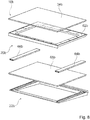
- FIG. 8 shows an exploded view of a storage unit 16b of an alternative home appliance device.
- the storage unit 16b has a pull-out element 20b with a first storage shelf 34b and with a frame 62b, on which the storage shelf 34b is placed.
- the pull-out element 20b is slidably mounted via two slide rails 64b, 66b connected to a base element 22b of the storage unit 16b.
- the base element 22b has a second storage plate 68b, which is at least substantially covered by the pull-out element 20b in an inserted state of the pull-out element 20b.
- the second storage shelf 68b is released so that, for example, foodstuffs can temporarily be placed on the second storage shelf 68b.
Landscapes
- Engineering & Computer Science (AREA)
- Chemical & Material Sciences (AREA)
- Combustion & Propulsion (AREA)
- Physics & Mathematics (AREA)
- Mechanical Engineering (AREA)
- Thermal Sciences (AREA)
- General Engineering & Computer Science (AREA)
- Drawers Of Furniture (AREA)
- Freezers Or Refrigerated Showcases (AREA)
- Refrigerator Housings (AREA)
Applications Claiming Priority (1)
| Application Number | Priority Date | Filing Date | Title |
|---|---|---|---|
| DE102016202191.5A DE102016202191A1 (de) | 2016-02-12 | 2016-02-12 | Haushaltsgerätevorrichtung |
Publications (1)
| Publication Number | Publication Date |
|---|---|
| EP3205961A1 true EP3205961A1 (fr) | 2017-08-16 |
Family
ID=57868145
Family Applications (1)
| Application Number | Title | Priority Date | Filing Date |
|---|---|---|---|
| EP17152596.7A Withdrawn EP3205961A1 (fr) | 2016-02-12 | 2017-01-23 | Dispositif d'appareil ménager |
Country Status (4)
| Country | Link |
|---|---|
| US (1) | US20170234605A1 (fr) |
| EP (1) | EP3205961A1 (fr) |
| CN (1) | CN206890944U (fr) |
| DE (1) | DE102016202191A1 (fr) |
Families Citing this family (4)
| Publication number | Priority date | Publication date | Assignee | Title |
|---|---|---|---|---|
| EP3759404A4 (fr) * | 2018-03-02 | 2022-06-08 | Electrolux Do Brasil S.A. | Structure de stockage pour un appareil réfrigérateur |
| US10670327B1 (en) * | 2018-12-07 | 2020-06-02 | Bsh Hausgeraete Gmbh | Household cooling appliance comprising a shelf device |
| DE102019109868A1 (de) * | 2019-04-15 | 2020-10-29 | Paul Hettich Gmbh & Co. Kg | Bodenelement |
| KR20210136367A (ko) * | 2020-05-07 | 2021-11-17 | 삼성전자주식회사 | 냉장고 |
Citations (6)
| Publication number | Priority date | Publication date | Assignee | Title |
|---|---|---|---|---|
| CA1037908A (fr) * | 1975-06-13 | 1978-09-05 | Canadian General Electric Company Limited | Etagere coulissante en porte-a-faux pour armoire |
| US4488412A (en) * | 1983-11-14 | 1984-12-18 | White Consolidated Industries, Inc. | Adjustable air duct for a meat keeper |
| GB2313040A (en) * | 1993-07-28 | 1997-11-19 | Gold Star Co | Shelf for a refrigerator |
| DE69315494T2 (de) * | 1992-07-13 | 1998-04-16 | Gemtron Corp | Kühlschrankregal mit abnehmbarer Gleitführung |
| US6227636B1 (en) * | 1999-11-15 | 2001-05-08 | Maytag Corporation | Refrigerator shelf and serving tray assembly |
| US20030132691A1 (en) * | 2000-12-22 | 2003-07-17 | Ames Shannon Wayne | Removable glass encapsulated shelves |
Family Cites Families (9)
| Publication number | Priority date | Publication date | Assignee | Title |
|---|---|---|---|---|
| US5403083A (en) * | 1993-03-01 | 1995-04-04 | Whirlpool Corporation | Laterally adjustable cantilever shelf for a refrigerator |
| GB2280359B (en) * | 1993-07-28 | 1998-01-14 | Gold Star Co | Shelf device for a refrigerator |
| CA2146791C (fr) * | 1994-04-29 | 2002-06-25 | Robert S. Herrmann | Etagere coulissante pour refrigerateur |
| US5813741A (en) * | 1996-01-23 | 1998-09-29 | White Consolidated Industries, Inc. | Adjustable shelf for a refrigerator |
| US6364136B1 (en) * | 2000-09-18 | 2002-04-02 | Display Systems, Inc. | Sliding height-adjustable tray shelf unit |
| US7306304B2 (en) * | 2004-05-18 | 2007-12-11 | Daewoo Electronics Corporation | Refrigerator shelf |
| KR102001929B1 (ko) * | 2013-03-08 | 2019-10-01 | 엘지전자 주식회사 | 냉장고 |
| US9212848B2 (en) * | 2013-03-15 | 2015-12-15 | Whirlpool Corporation | Apparatus, system, and method for storage in a refrigerated appliance |
| US9335089B1 (en) * | 2014-11-20 | 2016-05-10 | Electrolux Home Products, Inc. | Armless slide under shelf |
-
2016
- 2016-02-12 DE DE102016202191.5A patent/DE102016202191A1/de not_active Withdrawn
-
2017
- 2017-01-23 EP EP17152596.7A patent/EP3205961A1/fr not_active Withdrawn
- 2017-02-10 CN CN201720123468.9U patent/CN206890944U/zh not_active Expired - Fee Related
- 2017-02-13 US US15/430,720 patent/US20170234605A1/en not_active Abandoned
Patent Citations (6)
| Publication number | Priority date | Publication date | Assignee | Title |
|---|---|---|---|---|
| CA1037908A (fr) * | 1975-06-13 | 1978-09-05 | Canadian General Electric Company Limited | Etagere coulissante en porte-a-faux pour armoire |
| US4488412A (en) * | 1983-11-14 | 1984-12-18 | White Consolidated Industries, Inc. | Adjustable air duct for a meat keeper |
| DE69315494T2 (de) * | 1992-07-13 | 1998-04-16 | Gemtron Corp | Kühlschrankregal mit abnehmbarer Gleitführung |
| GB2313040A (en) * | 1993-07-28 | 1997-11-19 | Gold Star Co | Shelf for a refrigerator |
| US6227636B1 (en) * | 1999-11-15 | 2001-05-08 | Maytag Corporation | Refrigerator shelf and serving tray assembly |
| US20030132691A1 (en) * | 2000-12-22 | 2003-07-17 | Ames Shannon Wayne | Removable glass encapsulated shelves |
Also Published As
| Publication number | Publication date |
|---|---|
| DE102016202191A1 (de) | 2017-08-17 |
| CN206890944U (zh) | 2018-01-16 |
| US20170234605A1 (en) | 2017-08-17 |
Similar Documents
| Publication | Publication Date | Title |
|---|---|---|
| EP3205960B1 (fr) | Appareil frigorifique ménager et procédé pour le montage de l'appareil frigorifique ménager | |
| EP2611331B1 (fr) | Élément coulissant de meuble | |
| DE102018108978A1 (de) | Ablageboden und Möbel oder Haushaltsgerät | |
| WO2015007607A1 (fr) | Appareil électroménager frigorifique pourvu d'une clayette et partie de préhension agencée coulissante sur la clayette | |
| EP2609385B1 (fr) | Appareil de froid équipé d'un contenant à produit réfrigéré extractible | |
| DE102016202191A1 (de) | Haushaltsgerätevorrichtung | |
| EP3199896B1 (fr) | Étagère de réfrigérateur dotée d'un élément ressort | |
| EP1882146A1 (fr) | Appareil frigorifique pourvu d'un bac a aliments refrigeres guide par des coulisses | |
| DE102010004219A1 (de) | Kühl- und/oder Gefriergerät | |
| WO2017137239A1 (fr) | Appareil ménager | |
| WO2017137240A1 (fr) | Appareil ménager | |
| EP3077743B1 (fr) | Appareil de froid électroménager à chariot porteur agencé coulissant dans le compartiment intérieur | |
| WO2013164179A1 (fr) | Dispositif de retenue pour un élément de support d'une armoire telle qu'un réfrigérateur, un congélateur ou une cave à vin | |
| EP2980513B1 (fr) | Support de produit refrigere pour un appareil frigorifique | |
| DE19916621C2 (de) | Kühlgerät mit Tragboden | |
| DE102012001374A1 (de) | Kühl- und/oder Gefriergerät | |
| EP3384809B1 (fr) | Dispositif de rangement | |
| DE102009037103A1 (de) | Haushaltsgerät, insbesondere Kühl- und/oder Gefriergerät | |
| DE102015203835A1 (de) | Haushaltskältegerät mit einem spezifischen Auszugswagen | |
| DE102016202189A1 (de) | Haushaltgerätevorrichtung | |
| EP3173719B1 (fr) | Appareil de réfrigération et/ou de congélation | |
| DE10339935A1 (de) | Kältegerät mit herausziehbarem Kühlgutträger | |
| DE102015012638A1 (de) | Türanordnung und Kühlmöbel | |
| DE102006018425A1 (de) | Teleskopauszug für ein Kältegerät | |
| DE102024002023A1 (de) | Türvorrichtung für Vitrinen |
Legal Events
| Date | Code | Title | Description |
|---|---|---|---|
| PUAI | Public reference made under article 153(3) epc to a published international application that has entered the european phase |
Free format text: ORIGINAL CODE: 0009012 |
|
| AK | Designated contracting states |
Kind code of ref document: A1 Designated state(s): AL AT BE BG CH CY CZ DE DK EE ES FI FR GB GR HR HU IE IS IT LI LT LU LV MC MK MT NL NO PL PT RO RS SE SI SK SM TR |
|
| AX | Request for extension of the european patent |
Extension state: BA ME |
|
| 17P | Request for examination filed |
Effective date: 20180216 |
|
| RBV | Designated contracting states (corrected) |
Designated state(s): AL AT BE BG CH CY CZ DE DK EE ES FI FR GB GR HR HU IE IS IT LI LT LU LV MC MK MT NL NO PL PT RO RS SE SI SK SM TR |
|
| 17Q | First examination report despatched |
Effective date: 20190910 |
|
| STAA | Information on the status of an ep patent application or granted ep patent |
Free format text: STATUS: THE APPLICATION HAS BEEN WITHDRAWN |
|
| 18W | Application withdrawn |
Effective date: 20200318 |