EP3205960B1 - Appareil frigorifique ménager et procédé pour le montage de l'appareil frigorifique ménager - Google Patents
Appareil frigorifique ménager et procédé pour le montage de l'appareil frigorifique ménager Download PDFInfo
- Publication number
- EP3205960B1 EP3205960B1 EP17152572.8A EP17152572A EP3205960B1 EP 3205960 B1 EP3205960 B1 EP 3205960B1 EP 17152572 A EP17152572 A EP 17152572A EP 3205960 B1 EP3205960 B1 EP 3205960B1
- Authority
- EP
- European Patent Office
- Prior art keywords
- retaining
- holding
- refrigeration appliance
- advantageously
- unit
- Prior art date
- Legal status (The legal status is an assumption and is not a legal conclusion. Google has not performed a legal analysis and makes no representation as to the accuracy of the status listed.)
- Active
Links
Images


Classifications
-
- F—MECHANICAL ENGINEERING; LIGHTING; HEATING; WEAPONS; BLASTING
- F25—REFRIGERATION OR COOLING; COMBINED HEATING AND REFRIGERATION SYSTEMS; HEAT PUMP SYSTEMS; MANUFACTURE OR STORAGE OF ICE; LIQUEFACTION SOLIDIFICATION OF GASES
- F25D—REFRIGERATORS; COLD ROOMS; ICE-BOXES; COOLING OR FREEZING APPARATUS NOT OTHERWISE PROVIDED FOR
- F25D23/00—General constructional features
- F25D23/06—Walls
- F25D23/065—Details
- F25D23/067—Supporting elements
-
- A—HUMAN NECESSITIES
- A47—FURNITURE; DOMESTIC ARTICLES OR APPLIANCES; COFFEE MILLS; SPICE MILLS; SUCTION CLEANERS IN GENERAL
- A47B—TABLES; DESKS; OFFICE FURNITURE; CABINETS; DRAWERS; GENERAL DETAILS OF FURNITURE
- A47B57/00—Cabinets, racks or shelf units, characterised by features for adjusting shelves or partitions
- A47B57/30—Cabinets, racks or shelf units, characterised by features for adjusting shelves or partitions with means for adjusting the height of detachable shelf supports
- A47B57/54—Cabinets, racks or shelf units, characterised by features for adjusting shelves or partitions with means for adjusting the height of detachable shelf supports consisting of clamping means, e.g. with sliding bolts or sliding wedges
- A47B57/545—Cabinets, racks or shelf units, characterised by features for adjusting shelves or partitions with means for adjusting the height of detachable shelf supports consisting of clamping means, e.g. with sliding bolts or sliding wedges clamped in discrete positions, e.g. on tubes with grooves or holes
-
- A—HUMAN NECESSITIES
- A47—FURNITURE; DOMESTIC ARTICLES OR APPLIANCES; COFFEE MILLS; SPICE MILLS; SUCTION CLEANERS IN GENERAL
- A47B—TABLES; DESKS; OFFICE FURNITURE; CABINETS; DRAWERS; GENERAL DETAILS OF FURNITURE
- A47B96/00—Details of cabinets, racks or shelf units not covered by a single one of groups A47B43/00 - A47B95/00; General details of furniture
- A47B96/02—Shelves
- A47B96/027—Cantilever shelves
-
- F—MECHANICAL ENGINEERING; LIGHTING; HEATING; WEAPONS; BLASTING
- F25—REFRIGERATION OR COOLING; COMBINED HEATING AND REFRIGERATION SYSTEMS; HEAT PUMP SYSTEMS; MANUFACTURE OR STORAGE OF ICE; LIQUEFACTION SOLIDIFICATION OF GASES
- F25D—REFRIGERATORS; COLD ROOMS; ICE-BOXES; COOLING OR FREEZING APPARATUS NOT OTHERWISE PROVIDED FOR
- F25D25/00—Charging, supporting, and discharging the articles to be cooled
- F25D25/02—Charging, supporting, and discharging the articles to be cooled by shelves
- F25D25/024—Slidable shelves
Definitions
- the invention relates to a household refrigeration appliance according to claim 1 and a method for assembling a household refrigeration appliance according to claim 12.
- Refrigerators with holding profiles are already known from the prior art, in which shelves can be hung at a locking position of the holding profile. To adjust the height of the storage shelves, the storage shelves can be unhooked and hung again at a different latching position of the holding profile.
- JP 2006 230544A shows another shelving system known from the prior art.
- the object of the invention is, in particular, to provide a device of the generic type with improved properties with regard to holding storage units.
- the object is achieved according to the invention by the features of patent claims 1 and 12, while advantageous configurations and developments of the invention can be found in the dependent claims.
- the invention is based on a household refrigeration appliance with at least one storage unit and with at least one holding unit, which has at least one vertical rail element and at least one the rail element has connected holding element, which is provided for holding the storage unit.
- the holding element is mounted on the rail element so that it can be adjusted in height in an at least essentially vertical direction.
- a “household appliance device” should be understood to mean in particular at least a part, in particular a subassembly, of a household appliance, in particular a household refrigeration appliance.
- the household appliance device can also be the entire household appliance, in particular the entire household refrigeration unit advises to include.
- the household appliance is particularly preferably designed as a refrigerator and/or freezer, in particular as a refrigerator, chest freezer, freezer, chest freezer, combined fridge-freezer and/or wine storage cabinet.
- a “storage unit” is to be understood in particular as a unit that is provided for putting down or depositing objects, in particular food.
- the storage unit can be designed at least essentially in the manner of a plate and/or have at least one element designed at least essentially in the manner of a plate.
- a "plate-like" object is to be understood in particular as an object that has a significantly greater extent along a first spatial direction and along a second spatial direction than along a third spatial direction, preferably by at least a factor of 5, advantageously by at least a factor of 10 and particularly advantageously an extension that is greater by at least a factor of 20, with the three spatial directions being intended to be perpendicular to one another in pairs.
- an “extension along a direction” of an object is to be understood in particular as a maximum distance between two points of a perpendicular projection of the object onto a plane that is parallel to the direction.
- the holding element has an at least substantially rectangular cross section.
- An "at least essentially rectangular cross-section" of an object should be understood in particular to mean that for at least 80% of all cross-sections of the object along at least one direction, a surface area of a differential area of the cross-section and a smallest rectangle surrounding the cross-section is a maximum of 20%, advantageously a maximum of 10 % and particularly advantageously a maximum of 5% of the area of the rectangle.
- the holding element is designed as a rectangular holding strip, advantageously as a holding strip that can be produced by means of extrusion.
- the holding element can be formed at least essentially from a metal and/or a plastic.
- the holding element is preferably designed as a hollow profile.
- “at least essentially” should be understood to mean in particular at least 75%, preferably at least 85% and particularly preferably at least 95%.
- the configuration according to the invention makes it possible in particular to provide an advantageous mounting for storage units.
- a simple and reliable Height adjustment of storage units can be achieved.
- a vertical position of storage units of the size of items that have been set, in particular groceries can be comfortably adjusted.
- a high degree of flexibility can be achieved.
- an interior can easily be adapted to the needs of an operator and/or user.
- comfortable operation can be achieved.
- a holding system for differently designed storage units can advantageously be provided.
- the use of largely flat inner walls is made possible, as a result of which they are particularly easy to clean.
- a new, very high-quality appearance can be achieved.
- the holding element is mounted on the rail element such that it can be moved in the guided direction.
- an object is "mounted in a guided and movable manner" on a second object is to be understood here in particular as meaning that the object can be moved in at least one normal operating state relative to the second object, in particular along a trajectory specified by the second object, in particular under Application of forces that average people can apply without significant effort, for example with a hand and/or with an arm and/or with one or more fingers.
- the holding unit has at least one carriage element that is mounted so as to be guided and movable along a main extension direction of the rail element and to which the holding element is fastened in at least one assembled state.
- a "main extension direction" of an object is to be understood in particular as a direction which runs parallel to a longest edge of the smallest imaginary cuboid which just about completely encloses the object.
- the holding unit has at least one fastening element which connects the holding element to the carriage element in at least one assembled state.
- Each holding element is particularly advantageously assigned two fastening elements which hold the holding element on two opposite sides, in particular at a distance which at least essentially corresponds to a length of the holding element along a main extension direction of the holding element.
- the fastening element is advantageously connected in one piece to the holding element.
- In one piece is to be understood in particular as being at least cohesively connected, for example by a welding process, a gluing process, an injection molding process and/or another process that appears sensible to the person skilled in the art, and/or advantageously formed in one piece, such as by production from a single cast and/or by production in one Single or multi-component injection molding process and advantageously from a single blank.
- the holding element is guided by the carriage element, in particular during a displacement of the holding element in a vertical direction.
- the carriage element is connected to the fastening element, in particular in one piece.
- the domestic appliance device advantageously comprises at least one appliance body with at least one rear wall, in the vicinity of which the holding unit is arranged.
- the appliance body of the household appliance device delimits and/or defines in particular an interior space, preferably at least one usable space, and in particular has an access opening.
- a door of the domestic appliance device that is arranged on a front side of the appliance body is designed differently from the appliance body.
- a “near area” is to be understood in particular as a spatial area whose points are at most 20 cm, advantageously at most 15 cm, particularly advantageously at most 10 cm and preferably at most 7 cm away from the rear wall.
- the holding unit is advantageously connected to the rear wall.
- the rail element of the holding unit is particularly advantageously connected to the rear wall. In this way, in particular, an advantageous utilization of the interior space can be achieved. Furthermore, advantageous properties with regard to cleaning storage units held from behind can be achieved in this way.
- the domestic appliance device has at least one panel element which is at least partially arranged on a side of the holding unit which is remote from the rear wall.
- at least 70%, advantageously at least 80%, particularly advantageously at least 90% and particularly preferably at least 95% of all points of the panel element are located on a respective straight line perpendicular to the rear wall through the corresponding point further away from the rear wall than the point furthest from the Rear wall distant point of the holding unit on the respective straight line.
- the panel element is connected to the holding unit.
- the screen element is advantageously connected in one piece to the holding unit.
- the screen element forms a front of the rear wall in a mounted state of the device body arranged rear wall element.
- the panel element advantageously has a height and a width which at least essentially correspond to a height and a width of the rear wall of the device body.
- “at least essentially” should be understood to mean a deviation of the height/width of the panel element from the height/width of the rear wall of at most 20%, advantageously at most 10% and particularly advantageously at most 5%.
- an interior space that is easy to clean can advantageously be provided.
- damage to and/or contamination of the holding unit can advantageously be avoided as a result.
- this can advantageously provide a rear wall element with special material and/or lighting options, which can be produced independently of a rear wall of a household appliance body.
- the retaining element is arranged at least partially on a side of the screen element that faces away from the rear wall.
- at least 70%, advantageously at least 80%, particularly advantageously at least 90% and particularly preferably at least 95% of all points of the holding element are located on a respective straight line perpendicular to the rear wall through the corresponding point further away from the rear wall than the point furthest from the Rear panel distant point of the screen element on the respective straight line.
- Two fastening elements of the holding unit are advantageously assigned to each holding element.
- the two fastening elements of the holding unit protrude on one side of the panel element past the panel element in the direction of the side of the panel element facing away from the rear wall and hold the holding element on the side of the panel element facing away from the rear wall.
- the panel element is preferably connected to the rail element.
- the screen element at least partially covers the holding unit on a side of the holding unit facing away from the rear wall.
- the panel element covers all parts of the holding unit apart from the holding elements and the fastening elements on the side of the holding unit facing away from the rear wall.
- a main extension direction of the holding element runs in at least one mounted state in an at least substantially horizontal direction.
- "At least essentially in the horizontal direction” is to be understood in particular as an alignment relative to a surface normal of a subsurface, in particular a surface of the earth, in particular in at least one normal operating state of the household appliance device, with the direction being different from a direction perpendicular to the surface normal of the subsurface, in particular less than 8°, advantageously less than 5° and particularly advantageously less than 2°.
- the main extension direction of the holding element advantageously runs at least essentially parallel to the rear wall of the device body.
- At least essentially parallel is to be understood here in particular as an alignment of a direction relative to a reference direction, in particular in a plane, with the direction relative to the reference direction deviating in particular by less than 8°, advantageously less than 5° and particularly advantageously less than 2°. In this way, advantageous statics can be achieved in particular. Furthermore, holding elements that are easy to clean can be provided in this way.
- the storage unit in the assembled state, be mounted on the holding unit, in particular on the holding element, such that it can be displaced in a direction parallel to the main extension direction of the holding element.
- a position of the object relative to the second object remains at least substantially unchanged when viewed parallel to the direction, whereas a position of the object relative to the second object changes when viewed perpendicular to the direction.
- “at least essentially unchanged” is to be understood in particular as meaning that the position of the object relative to the second object changes by less than 10 mm, advantageously by less than 5 mm and particularly advantageously by less than 1 mm.
- the storage unit is movably mounted in a loaded state and in an unloaded state.
- a domestic appliance device can be adapted to an arrangement and/or to a size of adjusted and/or inserted objects, such as food. Comfortable operation can also advantageously be achieved.
- the rail element advantageously has at least one latching means which provides at least two different latching positions for the holding element.
- the latching means is designed as at least part of a toothed rack.
- the rail element preferably has at least one rail profile, in particular a rail profile which is open towards one of its longitudinal sides. Particularly preferably, a plurality of latching means form the rail profile. But it is also conceivable that the latching means is arranged inside the rail profile.
- the rail element advantageously has a cover profile which covers at least a large part of the open longitudinal side of the rail profile. In a particularly advantageous manner, the covering profile covers at least a large part of the latching means and the open longitudinal side of the rail profile.
- At least a large part is to be understood in particular as at least 55%, advantageously at least 65%, preferably at least 75%, particularly preferably at least 85% and particularly advantageously at least 95%.
- a vertical position of a storage unit can advantageously be fixed.
- a storage unit can advantageously be held securely in this way.
- a locking position of the holding element can be changed without tools in a particularly advantageous manner.
- a locking position of the holding element is possible in a one-hand operation, in particular for an average person, in particular without any significant effort. This enables convenient operation.
- the holding element be mounted such that it can be tilted in relation to the rail element in order to change the locking position.
- the holding element is mounted in such a way that, to change the locking position, an upper edge of the holding element is tilted in a direction towards the rear wall and/or a lower edge is tilted in a direction away from the rear wall.
- the carriage element has at least one latching lug, which is moved out of a latching position of the latching rail when the holding element is tilted.
- the carriage element can advantageously be displaced along a main extension direction of the rail element when the holding element is in a tilted state.
- the holding unit has at least one spring element, which is provided for the purpose of automatically turning the holding element into a to tilt in the non-tilted state.
- a minimum distance between the holding element and the panel element is preferably smaller than the diameter of an average human finger, in particular significantly smaller, in particular when the holding element is in a non-tilted state.
- a minimum distance between the holding element and the screen element is larger, in particular significantly larger, than the diameter of an average human finger, in particular when the holding element is in a tilted state.
- a height adjustment that is easy to operate can be provided.
- a secure mechanism for a height adjustment can advantageously be provided in this way.
- trapping of fingers can advantageously be avoided.
- the storage unit is provided to lock at least one latching position of the holding element in at least one assembled state.
- the storage unit has at least one extension that locks a tilting movement of the holding element relative to the rear wall.
- the extension is advantageously designed as a hook profile which is positively connected to the holding element in a mounted state.
- the extension is particularly advantageously connected in a form-fitting manner to a screen element of the holding unit. This advantageously avoids accidental height adjustment.
- this advantageously secures a position of a storage unit.
- storage units secure themselves against falling out. As a result, a very stable system with little tolerance can advantageously be provided.
- the storage unit be provided for tool-free assembly and/or disassembly on/from the holding unit.
- the storage unit can be assembled and/or disassembled by a linear movement and/or a tilting movement of the storage unit relative to the holding unit. In this way, a simple height adjustment of the storage unit can advantageously be achieved. In this way, an arrangement of storage units can also advantageously be conveniently adapted.
- the storage unit advantageously has at least one storage shelf.
- a "storage plate” is to be understood in particular as a plate-like element which is provided for placing or setting down objects, in particular food is. In this way, objects, in particular foodstuffs, can advantageously be set down safely on the storage unit. In particular, this advantageously makes it easy to clean the storage unit.
- the shelf is preferably at least partially transparent and frameless and/or at least partially translucent and frameless.
- At least partially “transparent” is to be understood in particular as at least partially transparent to visible light, in particular a transparency of at least 5%, preferably at least 10%, particularly preferably at least 20%, advantageously at least 50% and particularly advantageously at least 80% %, wherein a transmitted light is at least substantially parallel to an incident light.
- At least partially “translucent” is to be understood in particular as at least partially translucent for visible light, in particular a permeability of at least 5%, preferably at least 10%, particularly preferably at least 20%, advantageously at least 50% and particularly advantageously at least 80% % for incident light, wherein exiting light is at least substantially scattered at an angle other than 0 relative to the incident light.
- “Frameless” is to be understood in particular as meaning that the entire shelf is made from one material.
- the shelf has the same cross-section towards its edges as at its edges.
- the shelf is at least partially made of glass, advantageously at least partially made of safety glass.
- the shelf can be formed at least partially from at least partially opaque glass, in particular frosted glass.
- the shelf is advantageously designed as a frameless glass plate. But it is also conceivable that the shelf is made of a plastic. As a result, objects located under the storage shelf can advantageously be visible through the storage shelf. In particular, ease of use can be increased as a result.
- the invention is based on a method for assembling a domestic refrigeration appliance according to one of the previously described embodiments, comprising the steps: providing at least one vertical rail element, at least one holding element, at least one carriage element and at least one fastening element, the carriage element and the fastening element being connectable to one another are; Arranging the holding element on the fastening element, the fastening element being pushed laterally into the holding element, and the holding element forming a rectangular holding strip; and placing the carriage member on the vertical rail member by the movement in the horizontal direction.
- the positioning of the retaining element on the fastening element is achieved by movement in the horizontal direction by means of telescoping and/or interlocking.
- the arrangement of the carriage element on the vertical rail element is preferably achieved by the movement in the horizontal direction by pushing in, preferably laterally, a locking lug of the carriage element into a locking position of the vertical rail element.
- the method preferably includes the further step: arranging a storage unit on the holding element.
- the arrangement is preferably achieved by hanging a hook profile of the storage unit on the holding element.
- the retaining element is mounted on the rail element so that it can be adjusted in height along an at least substantially vertical direction.
- an advantageous mounting of storage units can be provided.
- a simple and reliable height adjustment of storage units can advantageously be achieved.
- a vertical position of objects placed in storage units, in particular groceries can be conveniently adjusted.
- a high degree of flexibility can be achieved.
- an interior can easily be adapted to the needs of an operator.
- comfortable operation can be achieved.
- a holding system for differently designed storage units can advantageously be provided.
- storage units can advantageously be arranged in a device body with predominantly flat inner walls, as a result of which the walls in particular are easy to clean.
- the domestic appliance device is not intended for the application described above and embodiment be limited.
- the household appliance device have a number of individual elements, components and units that differs from a number specified herein in order to fulfill a functionality described herein.
- FIG 1 shows a household appliance 32 embodied as a refrigerator with a household appliance device with a device body 10 in a perspective view.
- FIG 2 shows an interior 34 of the appliance body 10 of the household appliance device.
- the device body 10 has a rear wall 12 which is covered by a panel element 28 of the household appliance device.
- a holding unit 16 of the household appliance device is arranged in an area of the rear wall 12 .
- the screen element 28 is at least partially arranged on a side of the holding unit 16 facing away from the rear wall 12 .
- the holding unit 16 has a plurality of holding elements 18 whose main direction of extent runs in a horizontal direction 17 .
- the holding elements 18 are arranged on a side of the screen element 28 facing away from the rear wall 12 .
- the domestic appliance device has two storage units 14, 38, each with a storage shelf 30, 40. In the present case, the shelves 30, 40 are designed as frameless safety glass panels.
- the domestic appliance device has a storage unit 36 designed as a bottle holder.
- the storage units 14, 36, 38 are each suspended from a holding element 18, which holds the corresponding storage unit 14, 36, 38 along a rear side 42, 44, 46 of the storage unit 14, 36, 38.
- the storage units 14, 36, 38 can be mounted on each of the holding elements 18 without tools.
- the storage units 14, 36, 38 can be removed from the corresponding holding element 18 without tools.
- the storage units 14, 36, 38 can be hooked onto the holding elements 18. But it is also conceivable that the storage units are designed to be pluggable.
- FIG 3 shows the holding unit 16, the panel element 28 and the three storage units 14, 36, 38 in a perspective view.
- the storage units 14, 36, 38 each have a hook profile 48, 50, 52, which at least partially surrounds the corresponding holding element 18 from an upper side 53.
- the upper side 53 is a side of the storage units 14, 36, 38 that faces away from a floor on which the household appliance 32 is standing in a normal operating state , which runs at least essentially parallel to the main axis of extension of the respective holding element 18 .
- the storage units 14, 36 have a width which corresponds to approximately half the length of one of the holding elements 18.
- the storage units 14, 36 can be displaced along the corresponding holding element 18 in an assembled state, in which the respective hook profile 48, 50 at least partially encompasses the corresponding holding element 18 from above.
- the storage units 14, 36 are in a left direction 76 and in a right direction Direction 78 slidably mounted.
- the left direction 76 and the right direction 78 run parallel to the horizontal direction 17.
- the storage units 14, 36 are slidably mounted in a loaded and in an unloaded state.
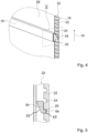
- FIG. 4 shows the holding unit 16 of the household appliance device in a perspective view.
- the holding unit 16 has a vertical rail element 20 on one side.
- the holding element 18 is mounted on the rail element 20 so that it can be adjusted in height in an at least essentially vertical direction 19 .
- the rail element 20 has a latching means 22 designed as a latching rail, which provides a plurality of latching positions 24 , 26 along a main direction of extent of the rail element 20 .
- the holding unit 16 has a carriage element 54 which is movably mounted and guided along the rail element 20 .
- the carriage element 54 is connected to a fastening element 56 which holds the holding element 18 in front of the panel element 28 .
- the carriage element 54 and the fastening element 56 are designed in one piece.
- the holding unit 16 has a further rail element 58 and a further carriage element 60 and a further fastening element 62 on another side (see FIG figure 8 ).
- figure 5 shows the carriage element 54 and the rail element 20 of the holding unit 16 in a sectional view along the sectional plane V in figure 4 .
- the carriage element 54 has a latching lug 64 which, in a latched state, latches into the latching positions 24, 26 of the latching means 22. Holding forces occurring when holding the storage units 14 , 36 , 38 can thus be introduced into the rail element 20 via the carriage element 54 .
- the carriage element 54 can preferably have an insertion aid 65 in one embodiment.
- the insertion aid 65 can be provided on the latching lug 64 .
- the insertion aid 65 advantageously facilitates locking into a locking position 24, 26 or unlocking/removing from a locking position 24, 26.
- FIG 6 shows the holding unit 16 during a height adjustment of a holding element 18 of the holding unit 16 in a perspective view.
- the holding element 18 is tiltably mounted on the rail element 20 .
- the holding element 18 can be tilted in such a way that an upper side 66 of the holding element 18 is closer together in a tilted state the panel element 28 is located as an underside 68 of the holding element 18.
- the holding element 18 can be adjusted in height.
- the carriage element 54 is moved up or down in a vertical direction along the main extension direction of the rail element 20 .
- the holding element 18 is movably mounted in a guided manner along the rail element 20 by means of the fastening element 56 and the carriage element 54 .
- a tilting of the holding element 18 and a subsequent height adjustment of the holding element 18 are possible without tools.
- figure 7 shows the carriage element 54 and the rail element 20 of the holding unit 16 during a height adjustment of the holding element 18 in a sectional view along the sectional plane V in figure 4 .
- the carriage element 54 is tilted.
- the carriage element 54 can then be moved along the rail element 20 and can be locked again at any other locking position 26 .
- the carriage element 54 can preferably have a contact surface 55 in one embodiment.
- the contact surface 55 preferably faces the screen element 28 .
- the contact surface 55 is arranged on a side of the carriage element 54 opposite the locking lug 64 .
- the contact surface 55 can be brought into contact with the screen element 28 when the height is adjusted.
- the panel element serves as a stop in this case, so that when tilting, a user receives an indication that maximum tilting has now been reached and trouble-free height adjustment is possible.
- Latching takes place by the holding element 18 tilting back, as a result of which the carriage element 54 tilts back.
- the latching lug 56 latches in a latching position 24 , 26 .
- the holding element 18 tilts back, in particular automatically, as a result of the force of gravity on the holding element 18 , in particular as soon as the operator lets go of the holding element 18 .
- FIG 8 shows an exploded view of the holding unit 16, the screen element 28 and a storage unit 38 of the household appliance device.
- the holding unit 16 has the two rail elements 20 , 58 .
- the rail elements 20, 58 each have a cover profile 70, 72 which at least partially covers the latching means 22, 74 of the rail elements 20, 58.
- the carriage elements 54, 60 of the holding unit 16 are each formed in one piece with a fastening element 56, 62 of the holding unit 16.
- the fastening elements 56, 62 can be pushed laterally into the holding element 18.
- the hook profile 52 of the storage unit 38 is positively connected to the holding element 18 in a mounted state. Furthermore, the hook profile 52 of the storage unit 38 is positively connected to the panel element 28 in an assembled state.
- the locking position 24, 26 of the holding element 18 is locked by the storage unit 38 in an assembled state.
- a storage unit 14 , 36 , 38 suspended from the holding element 18 may first have to be removed from the holding element 18 .
Landscapes
- Engineering & Computer Science (AREA)
- Chemical & Material Sciences (AREA)
- Combustion & Propulsion (AREA)
- Physics & Mathematics (AREA)
- Mechanical Engineering (AREA)
- Thermal Sciences (AREA)
- General Engineering & Computer Science (AREA)
- Drawers Of Furniture (AREA)
- Supports Or Holders For Household Use (AREA)
Claims (12)
- Appareil frigorifique ménager comprenant au moins une unité d'entreposage (14) et au moins un ensemble de retenue (16), qui comprend au moins un élément de rail vertical (20) et au moins un élément de retenue (18) relié à l'élément de rail, qui maintient l'unité d'entreposage (14),dans lequel l'élément de retenue (18) est monté de façon réglable en hauteur sur l'élément de rail (20) dans une direction au moins essentiellement verticale (19), dans lequel l'ensemble de retenue (16) comprend un élément de coulisseau (54, 60), qui est monté de manière mobile et guidée le long de l'élément de rail (20), l'élément de coulisseau (54, 60) étant relié à un élément de fixation (56, 62) de l'ensemble de retenue (16),caractérisé en ce que l'élément de fixation (56, 62) est inséré latéralement dans l'élément de retenue (18) et dans lequel l'élément de retenue (18) est configuré sous forme d'une barrette de retenue rectangulaire.
- Appareil frigorifique ménager selon la revendication 1, caractérisé par au moins une carrosserie d'appareil (10), qui comprend au moins une paroi arrière (12), à proximité de laquelle l'ensemble de retenue (16) est disposé.
- Appareil frigorifique ménager selon la revendication 2, caractérisé par au moins un élément de panneau (28), qui est disposé au moins en partie sur un côté de l'ensemble de retenue (16) opposé à la paroi arrière (12).
- Appareil frigorifique ménager selon la revendication 3, caractérisé en ce que l'élément de retenue (18) est disposé au moins en partie sur un côté de l'élément de panneau (28) opposé à la paroi arrière (12).
- Appareil frigorifique ménager selon l'une des revendications précédentes, caractérisé en ce qu'une direction principale d'extension de l'élément de retenue (18) s'étend, dans au moins un état monté, dans une direction au moins essentiellement horizontale.
- Appareil frigorifique ménager selon la revendication 5, caractérisé en ce que l'unité d'entreposage (14) est montée de façon à pouvoir se déplacer sur l'ensemble de retenue, dans l'état monté, dans une direction parallèle à la direction principale d'extension de l'élément de retenue (18).
- Appareil frigorifique ménager selon l'une des revendications précédentes, caractérisé en ce que l'élément de rail (20) comprend au moins un moyen d'encliquetage (22), qui fournit au moins deux positions d'encliquetage différentes (24, 26) pour l'élément de retenue (18).
- Appareil frigorifique ménager selon la revendication 7, caractérisé en ce qu'une position d'encliquetage (24, 26) de l'élément de retenue (18) peut être modifiée sans outil.
- Appareil frigorifique ménager selon la revendication 8, caractérisé en ce que l'élément de retenue (18) est monté de façon à pouvoir basculer vis-à-vis de l'élément de rail (20) pour une modification de la position d'encliquetage (24, 26).
- Appareil frigorifique ménager selon l'une des revendications 7 à 9, caractérisé en ce que l'unité d'entreposage (14) verrouille, dans au moins un état monté, au moins une position d'encliquetage (24, 26) de l'élément de retenue (18).
- Appareil frigorifique ménager selon l'une des revendications précédentes, caractérisé en ce que l'unité d'entreposage (14) peut être montée sur l'ensemble de retenue (16) et/ou démontée de l'ensemble de retenue (16) sans outil.
- Procédé de montage d'un appareil frigorifique ménager selon l'une des revendications 1 à 11, comprenant les étapes suivantes :- fourniture d'au moins un élément de rail vertical (20), d'au moins un élément de retenue (18), d'au moins un élément de coulisseau (54) et d'au moins un élément de fixation (56), l'élément de coulisseau (54) et l'élément de fixation (56) pouvant être connectés l'un à l'autre,- montage de l'élément de retenue (18) sur l'élément de fixation (56), dans lequel l'élément de fixation (56, 62) est inséré latéralement dans l'élément de retenue (18), et dans lequel l'élément de retenue est configuré sous forme d'une barrette de retenue rectangulaire, et- montage de l'élément de coulisseau (54) sur l'élément de rail vertical (20) par un déplacement dans la direction horizontale (76, 78).
Applications Claiming Priority (1)
| Application Number | Priority Date | Filing Date | Title |
|---|---|---|---|
| DE102016202190.7A DE102016202190A1 (de) | 2016-02-12 | 2016-02-12 | Haushaltsgerätevorrichtung |
Publications (2)
| Publication Number | Publication Date |
|---|---|
| EP3205960A1 EP3205960A1 (fr) | 2017-08-16 |
| EP3205960B1 true EP3205960B1 (fr) | 2023-07-19 |
Family
ID=57882000
Family Applications (1)
| Application Number | Title | Priority Date | Filing Date |
|---|---|---|---|
| EP17152572.8A Active EP3205960B1 (fr) | 2016-02-12 | 2017-01-23 | Appareil frigorifique ménager et procédé pour le montage de l'appareil frigorifique ménager |
Country Status (4)
| Country | Link |
|---|---|
| US (1) | US20170234604A1 (fr) |
| EP (1) | EP3205960B1 (fr) |
| CN (1) | CN206891014U (fr) |
| DE (1) | DE102016202190A1 (fr) |
Families Citing this family (7)
| Publication number | Priority date | Publication date | Assignee | Title |
|---|---|---|---|---|
| DE102017001178A1 (de) * | 2016-11-08 | 2018-05-09 | Liebherr-Hausgeräte Lienz Gmbh | Kühl- und/oder Gefriergerät |
| DE102016013440A1 (de) * | 2016-11-10 | 2018-05-17 | Liebherr-Hausgeräte Lienz Gmbh | Kühl- und/oder Gefriergerät |
| US10827834B2 (en) * | 2018-10-22 | 2020-11-10 | Haier Us Appliance Solutions, Inc. | Bottle support assembly for a refrigerator appliance |
| DE102019114418A1 (de) * | 2019-04-18 | 2020-10-22 | Liebherr-Hausgeräte Lienz Gmbh | Kühl- und/oder Gefriergerät |
| CN113932543B (zh) * | 2020-07-13 | 2023-05-16 | 青岛海尔电冰箱有限公司 | 用于冰箱的搁架组件及冰箱 |
| DE102020211569A1 (de) | 2020-09-15 | 2022-03-17 | BSH Hausgeräte GmbH | Ablageplattenanordnung mit Trägerrahmen mit einer Profilschiene aus Metall, sowie Haushaltskältegerät |
| DE102020211570A1 (de) | 2020-09-15 | 2022-03-17 | BSH Hausgeräte GmbH | Einhängevorrichtung für einen Lebensmittel-Aufnahmebehälter mit einer Profilschiene aus Metall, Anordnung sowie Haushaltskältegerätbauteil |
Family Cites Families (15)
| Publication number | Priority date | Publication date | Assignee | Title |
|---|---|---|---|---|
| BE793808A (fr) * | 1972-01-10 | 1973-07-10 | Westinghouse Electric Corp | Supports de lignes de raccordement |
| IT8421447U1 (it) * | 1984-04-05 | 1985-10-05 | Ire Ind Riunite Eurodomestici Spa | Supporto amovibile portaoggetti a mensola, particolarmente per frigoriferi domestici |
| KR930000044Y1 (ko) * | 1991-01-29 | 1993-01-09 | 삼성전자 주식회사 | 복합냉장고의 식품용기 수납장치 |
| CA2097221C (fr) * | 1992-12-11 | 2000-02-22 | Kevin C. Bird | Rayonnage reglable pour refrigerateur |
| US5390802A (en) * | 1993-02-12 | 1995-02-21 | Hmg Worldwide In-Store Marketing, Inc. | Shelf assembly for gondola display structure |
| US5403083A (en) * | 1993-03-01 | 1995-04-04 | Whirlpool Corporation | Laterally adjustable cantilever shelf for a refrigerator |
| US5452812A (en) * | 1993-07-13 | 1995-09-26 | Sycamore Systems, Inc. | Shelving system |
| US5769520A (en) * | 1993-08-02 | 1998-06-23 | Goldstar Co., Ltd. | Shelf device for a refrigerator |
| US6065821A (en) * | 1998-05-15 | 2000-05-23 | Maytag Corporation | Vertically adjustable shelf and support rail arrangement for use in a cabinet |
| JP4113880B2 (ja) * | 2005-02-23 | 2008-07-09 | 株式会社泉美 | 商品陳列台の商品支持具受け用部材 |
| US8608264B2 (en) * | 2006-04-28 | 2013-12-17 | Whirlpool Corporation | Refrigerator rail system for removably supported side-sliding shelves |
| DE102006061152A1 (de) * | 2006-12-22 | 2008-06-26 | BSH Bosch und Siemens Hausgeräte GmbH | Kältegerät |
| US8182056B2 (en) * | 2007-09-05 | 2012-05-22 | Electrolux Home Products, Inc. | Offset weight supporting slide |
| DE102011079197A1 (de) * | 2011-07-14 | 2013-01-17 | BSH Bosch und Siemens Hausgeräte GmbH | Haushaltskältegerät mit einer abnehmbar angeordneten Innenwandabdeckung |
| US9261305B2 (en) * | 2013-03-07 | 2016-02-16 | Whirlpool Corporation | Shelving assembly for refrigerator compartment |
-
2016
- 2016-02-12 DE DE102016202190.7A patent/DE102016202190A1/de not_active Withdrawn
-
2017
- 2017-01-23 EP EP17152572.8A patent/EP3205960B1/fr active Active
- 2017-02-10 CN CN201720123517.9U patent/CN206891014U/zh not_active Expired - Fee Related
- 2017-02-13 US US15/430,717 patent/US20170234604A1/en not_active Abandoned
Also Published As
| Publication number | Publication date |
|---|---|
| US20170234604A1 (en) | 2017-08-17 |
| DE102016202190A1 (de) | 2017-08-17 |
| EP3205960A1 (fr) | 2017-08-16 |
| CN206891014U (zh) | 2018-01-16 |
Similar Documents
| Publication | Publication Date | Title |
|---|---|---|
| EP3205960B1 (fr) | Appareil frigorifique ménager et procédé pour le montage de l'appareil frigorifique ménager | |
| EP2765886B1 (fr) | Dispositif de stockage d'ustensiles | |
| AT511091B1 (de) | Schubladenzarge mit neigungsverstellung | |
| EP1537365B1 (fr) | Four a systeme sortant lineaire | |
| DE10216769A1 (de) | Konsole für Tragböden in Haushaltsgeräten | |
| EP1984687A2 (fr) | Appareil frigorifique à clayette | |
| EP2276986B1 (fr) | Appareil frigorifique | |
| EP3205961A1 (fr) | Dispositif d'appareil ménager | |
| DE102010047039B4 (de) | Warenregal und Warenregalverglasung | |
| DE10230508A1 (de) | Kühlgerät | |
| EP3358258B1 (fr) | Meubles | |
| WO2017137239A1 (fr) | Appareil ménager | |
| DE202013003374U1 (de) | Auszugsvorrichtung für Schrankauszüge | |
| DE102015005666A1 (de) | Türanordnung für Kühlvitrine | |
| DE102016202187A1 (de) | Haushaltsgerätevorrichtung | |
| DE102012001374B4 (de) | Kühl- und/oder Gefriergerät | |
| EP2512296A2 (fr) | Comptoir à marchandises | |
| EP2585776B1 (fr) | Appareil de froid domestique | |
| DE19916621C2 (de) | Kühlgerät mit Tragboden | |
| EP3414500B1 (fr) | Appareil ménager frigorifique et procédé avec un appareil ménager frigorifique | |
| DE102015012638A1 (de) | Türanordnung und Kühlmöbel | |
| DE202015003240U1 (de) | Türanordnung für Kühlvitrine | |
| DE4343710A1 (de) | Haushaltsgerät zum Einbau in eine Küchenzeile | |
| EP3112761B1 (fr) | Hotte aspirante avec écran d'extraction | |
| DE19527731A1 (de) | Kühlschrank |
Legal Events
| Date | Code | Title | Description |
|---|---|---|---|
| PUAI | Public reference made under article 153(3) epc to a published international application that has entered the european phase |
Free format text: ORIGINAL CODE: 0009012 |
|
| STAA | Information on the status of an ep patent application or granted ep patent |
Free format text: STATUS: THE APPLICATION HAS BEEN PUBLISHED |
|
| AK | Designated contracting states |
Kind code of ref document: A1 Designated state(s): AL AT BE BG CH CY CZ DE DK EE ES FI FR GB GR HR HU IE IS IT LI LT LU LV MC MK MT NL NO PL PT RO RS SE SI SK SM TR |
|
| AX | Request for extension of the european patent |
Extension state: BA ME |
|
| STAA | Information on the status of an ep patent application or granted ep patent |
Free format text: STATUS: REQUEST FOR EXAMINATION WAS MADE |
|
| 17P | Request for examination filed |
Effective date: 20180216 |
|
| RBV | Designated contracting states (corrected) |
Designated state(s): AL AT BE BG CH CY CZ DE DK EE ES FI FR GB GR HR HU IE IS IT LI LT LU LV MC MK MT NL NO PL PT RO RS SE SI SK SM TR |
|
| STAA | Information on the status of an ep patent application or granted ep patent |
Free format text: STATUS: EXAMINATION IS IN PROGRESS |
|
| 17Q | First examination report despatched |
Effective date: 20190719 |
|
| GRAP | Despatch of communication of intention to grant a patent |
Free format text: ORIGINAL CODE: EPIDOSNIGR1 |
|
| STAA | Information on the status of an ep patent application or granted ep patent |
Free format text: STATUS: GRANT OF PATENT IS INTENDED |
|
| INTG | Intention to grant announced |
Effective date: 20230307 |
|
| GRAS | Grant fee paid |
Free format text: ORIGINAL CODE: EPIDOSNIGR3 |
|
| GRAA | (expected) grant |
Free format text: ORIGINAL CODE: 0009210 |
|
| STAA | Information on the status of an ep patent application or granted ep patent |
Free format text: STATUS: THE PATENT HAS BEEN GRANTED |
|
| AK | Designated contracting states |
Kind code of ref document: B1 Designated state(s): AL AT BE BG CH CY CZ DE DK EE ES FI FR GB GR HR HU IE IS IT LI LT LU LV MC MK MT NL NO PL PT RO RS SE SI SK SM TR |
|
| REG | Reference to a national code |
Ref country code: GB Ref legal event code: FG4D Free format text: NOT ENGLISH |
|
| REG | Reference to a national code |
Ref country code: CH Ref legal event code: EP |
|
| REG | Reference to a national code |
Ref country code: DE Ref legal event code: R096 Ref document number: 502017015066 Country of ref document: DE |
|
| P01 | Opt-out of the competence of the unified patent court (upc) registered |
Effective date: 20230707 |
|
| REG | Reference to a national code |
Ref country code: IE Ref legal event code: FG4D Free format text: LANGUAGE OF EP DOCUMENT: GERMAN |
|
| REG | Reference to a national code |
Ref country code: LT Ref legal event code: MG9D |
|
| REG | Reference to a national code |
Ref country code: NL Ref legal event code: MP Effective date: 20230719 |
|
| PG25 | Lapsed in a contracting state [announced via postgrant information from national office to epo] |
Ref country code: NL Free format text: LAPSE BECAUSE OF FAILURE TO SUBMIT A TRANSLATION OF THE DESCRIPTION OR TO PAY THE FEE WITHIN THE PRESCRIBED TIME-LIMIT Effective date: 20230719 |
|
| PG25 | Lapsed in a contracting state [announced via postgrant information from national office to epo] |
Ref country code: GR Free format text: LAPSE BECAUSE OF FAILURE TO SUBMIT A TRANSLATION OF THE DESCRIPTION OR TO PAY THE FEE WITHIN THE PRESCRIBED TIME-LIMIT Effective date: 20231020 |
|
| PG25 | Lapsed in a contracting state [announced via postgrant information from national office to epo] |
Ref country code: IS Free format text: LAPSE BECAUSE OF FAILURE TO SUBMIT A TRANSLATION OF THE DESCRIPTION OR TO PAY THE FEE WITHIN THE PRESCRIBED TIME-LIMIT Effective date: 20231119 |
|
| PG25 | Lapsed in a contracting state [announced via postgrant information from national office to epo] |
Ref country code: SE Free format text: LAPSE BECAUSE OF FAILURE TO SUBMIT A TRANSLATION OF THE DESCRIPTION OR TO PAY THE FEE WITHIN THE PRESCRIBED TIME-LIMIT Effective date: 20230719 Ref country code: RS Free format text: LAPSE BECAUSE OF FAILURE TO SUBMIT A TRANSLATION OF THE DESCRIPTION OR TO PAY THE FEE WITHIN THE PRESCRIBED TIME-LIMIT Effective date: 20230719 Ref country code: PT Free format text: LAPSE BECAUSE OF FAILURE TO SUBMIT A TRANSLATION OF THE DESCRIPTION OR TO PAY THE FEE WITHIN THE PRESCRIBED TIME-LIMIT Effective date: 20231120 Ref country code: NO Free format text: LAPSE BECAUSE OF FAILURE TO SUBMIT A TRANSLATION OF THE DESCRIPTION OR TO PAY THE FEE WITHIN THE PRESCRIBED TIME-LIMIT Effective date: 20231019 Ref country code: LV Free format text: LAPSE BECAUSE OF FAILURE TO SUBMIT A TRANSLATION OF THE DESCRIPTION OR TO PAY THE FEE WITHIN THE PRESCRIBED TIME-LIMIT Effective date: 20230719 Ref country code: LT Free format text: LAPSE BECAUSE OF FAILURE TO SUBMIT A TRANSLATION OF THE DESCRIPTION OR TO PAY THE FEE WITHIN THE PRESCRIBED TIME-LIMIT Effective date: 20230719 Ref country code: IS Free format text: LAPSE BECAUSE OF FAILURE TO SUBMIT A TRANSLATION OF THE DESCRIPTION OR TO PAY THE FEE WITHIN THE PRESCRIBED TIME-LIMIT Effective date: 20231119 Ref country code: HR Free format text: LAPSE BECAUSE OF FAILURE TO SUBMIT A TRANSLATION OF THE DESCRIPTION OR TO PAY THE FEE WITHIN THE PRESCRIBED TIME-LIMIT Effective date: 20230719 Ref country code: GR Free format text: LAPSE BECAUSE OF FAILURE TO SUBMIT A TRANSLATION OF THE DESCRIPTION OR TO PAY THE FEE WITHIN THE PRESCRIBED TIME-LIMIT Effective date: 20231020 Ref country code: FI Free format text: LAPSE BECAUSE OF FAILURE TO SUBMIT A TRANSLATION OF THE DESCRIPTION OR TO PAY THE FEE WITHIN THE PRESCRIBED TIME-LIMIT Effective date: 20230719 |
|
| PG25 | Lapsed in a contracting state [announced via postgrant information from national office to epo] |
Ref country code: PL Free format text: LAPSE BECAUSE OF FAILURE TO SUBMIT A TRANSLATION OF THE DESCRIPTION OR TO PAY THE FEE WITHIN THE PRESCRIBED TIME-LIMIT Effective date: 20230719 |
|
| REG | Reference to a national code |
Ref country code: DE Ref legal event code: R097 Ref document number: 502017015066 Country of ref document: DE |
|
| PG25 | Lapsed in a contracting state [announced via postgrant information from national office to epo] |
Ref country code: ES Free format text: LAPSE BECAUSE OF FAILURE TO SUBMIT A TRANSLATION OF THE DESCRIPTION OR TO PAY THE FEE WITHIN THE PRESCRIBED TIME-LIMIT Effective date: 20230719 |
|
| PG25 | Lapsed in a contracting state [announced via postgrant information from national office to epo] |
Ref country code: SM Free format text: LAPSE BECAUSE OF FAILURE TO SUBMIT A TRANSLATION OF THE DESCRIPTION OR TO PAY THE FEE WITHIN THE PRESCRIBED TIME-LIMIT Effective date: 20230719 Ref country code: RO Free format text: LAPSE BECAUSE OF FAILURE TO SUBMIT A TRANSLATION OF THE DESCRIPTION OR TO PAY THE FEE WITHIN THE PRESCRIBED TIME-LIMIT Effective date: 20230719 Ref country code: ES Free format text: LAPSE BECAUSE OF FAILURE TO SUBMIT A TRANSLATION OF THE DESCRIPTION OR TO PAY THE FEE WITHIN THE PRESCRIBED TIME-LIMIT Effective date: 20230719 Ref country code: EE Free format text: LAPSE BECAUSE OF FAILURE TO SUBMIT A TRANSLATION OF THE DESCRIPTION OR TO PAY THE FEE WITHIN THE PRESCRIBED TIME-LIMIT Effective date: 20230719 Ref country code: DK Free format text: LAPSE BECAUSE OF FAILURE TO SUBMIT A TRANSLATION OF THE DESCRIPTION OR TO PAY THE FEE WITHIN THE PRESCRIBED TIME-LIMIT Effective date: 20230719 Ref country code: CZ Free format text: LAPSE BECAUSE OF FAILURE TO SUBMIT A TRANSLATION OF THE DESCRIPTION OR TO PAY THE FEE WITHIN THE PRESCRIBED TIME-LIMIT Effective date: 20230719 Ref country code: SK Free format text: LAPSE BECAUSE OF FAILURE TO SUBMIT A TRANSLATION OF THE DESCRIPTION OR TO PAY THE FEE WITHIN THE PRESCRIBED TIME-LIMIT Effective date: 20230719 |
|
| PLBE | No opposition filed within time limit |
Free format text: ORIGINAL CODE: 0009261 |
|
| STAA | Information on the status of an ep patent application or granted ep patent |
Free format text: STATUS: NO OPPOSITION FILED WITHIN TIME LIMIT |
|
| PG25 | Lapsed in a contracting state [announced via postgrant information from national office to epo] |
Ref country code: IT Free format text: LAPSE BECAUSE OF FAILURE TO SUBMIT A TRANSLATION OF THE DESCRIPTION OR TO PAY THE FEE WITHIN THE PRESCRIBED TIME-LIMIT Effective date: 20230719 |
|
| 26N | No opposition filed |
Effective date: 20240422 |
|
| PG25 | Lapsed in a contracting state [announced via postgrant information from national office to epo] |
Ref country code: SI Free format text: LAPSE BECAUSE OF FAILURE TO SUBMIT A TRANSLATION OF THE DESCRIPTION OR TO PAY THE FEE WITHIN THE PRESCRIBED TIME-LIMIT Effective date: 20230719 |
|
| REG | Reference to a national code |
Ref country code: DE Ref legal event code: R119 Ref document number: 502017015066 Country of ref document: DE |
|
| PG25 | Lapsed in a contracting state [announced via postgrant information from national office to epo] |
Ref country code: MC Free format text: LAPSE BECAUSE OF FAILURE TO SUBMIT A TRANSLATION OF THE DESCRIPTION OR TO PAY THE FEE WITHIN THE PRESCRIBED TIME-LIMIT Effective date: 20230719 |
|
| PG25 | Lapsed in a contracting state [announced via postgrant information from national office to epo] |
Ref country code: MC Free format text: LAPSE BECAUSE OF FAILURE TO SUBMIT A TRANSLATION OF THE DESCRIPTION OR TO PAY THE FEE WITHIN THE PRESCRIBED TIME-LIMIT Effective date: 20230719 |
|
| REG | Reference to a national code |
Ref country code: CH Ref legal event code: PL |
|
| PG25 | Lapsed in a contracting state [announced via postgrant information from national office to epo] |
Ref country code: LU Free format text: LAPSE BECAUSE OF NON-PAYMENT OF DUE FEES Effective date: 20240123 |
|
| GBPC | Gb: european patent ceased through non-payment of renewal fee |
Effective date: 20240123 |
|
| PG25 | Lapsed in a contracting state [announced via postgrant information from national office to epo] |
Ref country code: LU Free format text: LAPSE BECAUSE OF NON-PAYMENT OF DUE FEES Effective date: 20240123 |
|
| PG25 | Lapsed in a contracting state [announced via postgrant information from national office to epo] |
Ref country code: DE Free format text: LAPSE BECAUSE OF NON-PAYMENT OF DUE FEES Effective date: 20240801 |
|
| PG25 | Lapsed in a contracting state [announced via postgrant information from national office to epo] |
Ref country code: GB Free format text: LAPSE BECAUSE OF NON-PAYMENT OF DUE FEES Effective date: 20240123 |
|
| PG25 | Lapsed in a contracting state [announced via postgrant information from national office to epo] |
Ref country code: BE Free format text: LAPSE BECAUSE OF NON-PAYMENT OF DUE FEES Effective date: 20240131 |
|
| PG25 | Lapsed in a contracting state [announced via postgrant information from national office to epo] |
Ref country code: FR Free format text: LAPSE BECAUSE OF NON-PAYMENT OF DUE FEES Effective date: 20240131 |
|
| PG25 | Lapsed in a contracting state [announced via postgrant information from national office to epo] |
Ref country code: CH Free format text: LAPSE BECAUSE OF NON-PAYMENT OF DUE FEES Effective date: 20240131 |
|
| PG25 | Lapsed in a contracting state [announced via postgrant information from national office to epo] |
Ref country code: GB Free format text: LAPSE BECAUSE OF NON-PAYMENT OF DUE FEES Effective date: 20240123 Ref country code: FR Free format text: LAPSE BECAUSE OF NON-PAYMENT OF DUE FEES Effective date: 20240131 Ref country code: DE Free format text: LAPSE BECAUSE OF NON-PAYMENT OF DUE FEES Effective date: 20240801 Ref country code: CH Free format text: LAPSE BECAUSE OF NON-PAYMENT OF DUE FEES Effective date: 20240131 Ref country code: BE Free format text: LAPSE BECAUSE OF NON-PAYMENT OF DUE FEES Effective date: 20240131 |
|
| REG | Reference to a national code |
Ref country code: BE Ref legal event code: MM Effective date: 20240131 |
|
| PG25 | Lapsed in a contracting state [announced via postgrant information from national office to epo] |
Ref country code: BG Free format text: LAPSE BECAUSE OF FAILURE TO SUBMIT A TRANSLATION OF THE DESCRIPTION OR TO PAY THE FEE WITHIN THE PRESCRIBED TIME-LIMIT Effective date: 20230719 |
|
| PG25 | Lapsed in a contracting state [announced via postgrant information from national office to epo] |
Ref country code: BG Free format text: LAPSE BECAUSE OF FAILURE TO SUBMIT A TRANSLATION OF THE DESCRIPTION OR TO PAY THE FEE WITHIN THE PRESCRIBED TIME-LIMIT Effective date: 20230719 |
|
| PG25 | Lapsed in a contracting state [announced via postgrant information from national office to epo] |
Ref country code: IE Free format text: LAPSE BECAUSE OF NON-PAYMENT OF DUE FEES Effective date: 20240123 |
|
| PG25 | Lapsed in a contracting state [announced via postgrant information from national office to epo] |
Ref country code: IE Free format text: LAPSE BECAUSE OF NON-PAYMENT OF DUE FEES Effective date: 20240123 |
|
| REG | Reference to a national code |
Ref country code: AT Ref legal event code: MM01 Ref document number: 1589844 Country of ref document: AT Kind code of ref document: T Effective date: 20240123 |
|
| PG25 | Lapsed in a contracting state [announced via postgrant information from national office to epo] |
Ref country code: AT Free format text: LAPSE BECAUSE OF NON-PAYMENT OF DUE FEES Effective date: 20240123 |
|
| PG25 | Lapsed in a contracting state [announced via postgrant information from national office to epo] |
Ref country code: CY Free format text: LAPSE BECAUSE OF FAILURE TO SUBMIT A TRANSLATION OF THE DESCRIPTION OR TO PAY THE FEE WITHIN THE PRESCRIBED TIME-LIMIT; INVALID AB INITIO Effective date: 20170123 |
|
| PG25 | Lapsed in a contracting state [announced via postgrant information from national office to epo] |
Ref country code: HU Free format text: LAPSE BECAUSE OF FAILURE TO SUBMIT A TRANSLATION OF THE DESCRIPTION OR TO PAY THE FEE WITHIN THE PRESCRIBED TIME-LIMIT; INVALID AB INITIO Effective date: 20170123 |
|
| PG25 | Lapsed in a contracting state [announced via postgrant information from national office to epo] |
Ref country code: TR Free format text: LAPSE BECAUSE OF FAILURE TO SUBMIT A TRANSLATION OF THE DESCRIPTION OR TO PAY THE FEE WITHIN THE PRESCRIBED TIME-LIMIT Effective date: 20230719 |