EP3206433B1 - Verfahren, vorrichtungen und system zum umschalten zwischen kleinen zellen - Google Patents
Verfahren, vorrichtungen und system zum umschalten zwischen kleinen zellen Download PDFInfo
- Publication number
- EP3206433B1 EP3206433B1 EP14905120.3A EP14905120A EP3206433B1 EP 3206433 B1 EP3206433 B1 EP 3206433B1 EP 14905120 A EP14905120 A EP 14905120A EP 3206433 B1 EP3206433 B1 EP 3206433B1
- Authority
- EP
- European Patent Office
- Prior art keywords
- small cell
- available
- beam pair
- base station
- high frequency
- Prior art date
- Legal status (The legal status is an assumption and is not a legal conclusion. Google has not performed a legal analysis and makes no representation as to the accuracy of the status listed.)
- Active
Links
Images


Classifications
-
- H—ELECTRICITY
- H04—ELECTRIC COMMUNICATION TECHNIQUE
- H04B—TRANSMISSION
- H04B7/00—Radio transmission systems, i.e. using radiation field
- H04B7/02—Diversity systems; Multi-antenna system, i.e. transmission or reception using multiple antennas
- H04B7/04—Diversity systems; Multi-antenna system, i.e. transmission or reception using multiple antennas using two or more spaced independent antennas
- H04B7/06—Diversity systems; Multi-antenna system, i.e. transmission or reception using multiple antennas using two or more spaced independent antennas at the transmitting station
- H04B7/0613—Diversity systems; Multi-antenna system, i.e. transmission or reception using multiple antennas using two or more spaced independent antennas at the transmitting station using simultaneous transmission
- H04B7/0615—Diversity systems; Multi-antenna system, i.e. transmission or reception using multiple antennas using two or more spaced independent antennas at the transmitting station using simultaneous transmission of weighted versions of same signal
- H04B7/0617—Diversity systems; Multi-antenna system, i.e. transmission or reception using multiple antennas using two or more spaced independent antennas at the transmitting station using simultaneous transmission of weighted versions of same signal for beam forming
-
- H—ELECTRICITY
- H04—ELECTRIC COMMUNICATION TECHNIQUE
- H04B—TRANSMISSION
- H04B7/00—Radio transmission systems, i.e. using radiation field
- H04B7/02—Diversity systems; Multi-antenna system, i.e. transmission or reception using multiple antennas
- H04B7/04—Diversity systems; Multi-antenna system, i.e. transmission or reception using multiple antennas using two or more spaced independent antennas
- H04B7/06—Diversity systems; Multi-antenna system, i.e. transmission or reception using multiple antennas using two or more spaced independent antennas at the transmitting station
- H04B7/0686—Hybrid systems, i.e. switching and simultaneous transmission
- H04B7/0695—Hybrid systems, i.e. switching and simultaneous transmission using beam selection
- H04B7/06952—Selecting one or more beams from a plurality of beams, e.g. beam training, management or sweeping
- H04B7/0696—Determining beam pairs
-
- H—ELECTRICITY
- H04—ELECTRIC COMMUNICATION TECHNIQUE
- H04L—TRANSMISSION OF DIGITAL INFORMATION, e.g. TELEGRAPHIC COMMUNICATION
- H04L5/00—Arrangements affording multiple use of the transmission path
- H04L5/003—Arrangements for allocating sub-channels of the transmission path
- H04L5/0048—Allocation of pilot signals, i.e. of signals known to the receiver
-
- H—ELECTRICITY
- H04—ELECTRIC COMMUNICATION TECHNIQUE
- H04W—WIRELESS COMMUNICATION NETWORKS
- H04W16/00—Network planning, e.g. coverage or traffic planning tools; Network deployment, e.g. resource partitioning or cells structures
- H04W16/18—Network planning tools
-
- H—ELECTRICITY
- H04—ELECTRIC COMMUNICATION TECHNIQUE
- H04W—WIRELESS COMMUNICATION NETWORKS
- H04W36/00—Hand-off or reselection arrangements
- H04W36/0005—Control or signalling for completing the hand-off
- H04W36/0055—Transmission or use of information for re-establishing the radio link
- H04W36/0061—Transmission or use of information for re-establishing the radio link of neighbour cell information
-
- H—ELECTRICITY
- H04—ELECTRIC COMMUNICATION TECHNIQUE
- H04W—WIRELESS COMMUNICATION NETWORKS
- H04W36/00—Hand-off or reselection arrangements
- H04W36/08—Reselecting an access point
- H04W36/085—Reselecting an access point involving beams of access points
-
- H—ELECTRICITY
- H04—ELECTRIC COMMUNICATION TECHNIQUE
- H04W—WIRELESS COMMUNICATION NETWORKS
- H04W36/00—Hand-off or reselection arrangements
- H04W36/24—Reselection being triggered by specific parameters
- H04W36/30—Reselection being triggered by specific parameters by measured or perceived connection quality data
- H04W36/304—Reselection being triggered by specific parameters by measured or perceived connection quality data due to measured or perceived resources with higher communication quality
-
- H—ELECTRICITY
- H04—ELECTRIC COMMUNICATION TECHNIQUE
- H04W—WIRELESS COMMUNICATION NETWORKS
- H04W56/00—Synchronisation arrangements
- H04W56/001—Synchronization between nodes
-
- H—ELECTRICITY
- H04—ELECTRIC COMMUNICATION TECHNIQUE
- H04W—WIRELESS COMMUNICATION NETWORKS
- H04W76/00—Connection management
- H04W76/10—Connection setup
-
- H—ELECTRICITY
- H04—ELECTRIC COMMUNICATION TECHNIQUE
- H04W—WIRELESS COMMUNICATION NETWORKS
- H04W24/00—Supervisory, monitoring or testing arrangements
- H04W24/10—Scheduling measurement reports ; Arrangements for measurement reports
-
- H—ELECTRICITY
- H04—ELECTRIC COMMUNICATION TECHNIQUE
- H04W—WIRELESS COMMUNICATION NETWORKS
- H04W36/00—Hand-off or reselection arrangements
- H04W36/16—Performing reselection for specific purposes
-
- H—ELECTRICITY
- H04—ELECTRIC COMMUNICATION TECHNIQUE
- H04W—WIRELESS COMMUNICATION NETWORKS
- H04W84/00—Network topologies
- H04W84/02—Hierarchically pre-organised networks, e.g. paging networks, cellular networks, WLAN [Wireless Local Area Network] or WLL [Wireless Local Loop]
- H04W84/04—Large scale networks; Deep hierarchical networks
- H04W84/042—Public Land Mobile systems, e.g. cellular systems
- H04W84/045—Public Land Mobile systems, e.g. cellular systems using private Base Stations, e.g. femto Base Stations, home Node B
Definitions
- the present invention relates to the field of communications technologies, and in particular, to an inter-small cell handover method, a device, and a system.
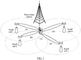
- FIG. 1 is a schematic diagram of an architecture of a high frequency network.
- the high frequency network includes: one macro base station, user equipment (UE for short), and multiple small cells (including a serving small cell performing data communication with the UE) in a coverage area of the macro base station.
- a small cell may perform data service transmission with the UE by using a high frequency band.
- a high frequency signal Compared with a low frequency signal, a high frequency signal has a severer transmission loss and a poorer penetration capability. Therefore, with impact of factors such as blocking of a building, blocking of a human body, and misalignment of a high frequency signal beam, the UE is extremely easily located in a coverage hole of the serving small cell. Consequently, a high frequency signal received by the UE is too poor to be demodulated, or the UE fails to receive a high frequency signal sent by the serving small cell, thereby affecting quality of receiving a high frequency service by the UE and a probability that the UE receives the high frequency service. Therefore, when the UE is in the coverage hole of the serving small cell, a corresponding measure needs to be taken, to reduce a probability that receiving a high frequency service by the UE is interrupted, and maintain continuity of data communication.
- the UE when UE is in a coverage hole of a serving small cell, the UE performs synchronous measurement on all high frequency beams of all small cells around the UE by using an initial synchronous measurement method, selects an optimal small cell and beam pair for re-access, and receives high frequency data sent by the small cell, ensuring continuity of high frequency data communication.
- the UE needs to perform synchronous measurement on all the beams of all the small cells, complexity is relatively high, and a synchronous measurement time is relatively long, thereby leading to a relatively large delay of re-access of the UE to another small cell, and reducing quality of service (QoS for short) of the UE.
- QoS quality of service
- US 2005/176385 A1 discloses a measurement for handoff by a wireless system.
- the switched beam antenna is a smart antenna generating a plurality of directional beams and an omni-directional beam.
- the WTRU measures signals from a plurality of cells with the omni-directional beam and/or one or more of the directional beams.
- Embodiments of the present invention provide an inter-small cell handover method, a device, and a system, so as to resolve a problem that when UE is in a coverage hole of a serving small cell, the UE performs synchronous measurement on all beams of all small cells, causing a relatively large access delay, and relatively low QoS of receiving a high frequency service by the UE.
- an embodiment of the present invention provides an inter-small cell handover method, including:
- the performing, by UE, synchronous measurement, to determine a set of small cells available for the UE includes:
- the method further includes:
- an embodiment of the present invention provides an inter-small cell handover method, including:
- the method before the instructing, by the macro base station according to the handover result, to perform data transmission between the target small cell and the UE by using the available target beam pair, the method further includes:
- an embodiment of the present invention provides an inter-small cell handover method, including:
- the method further includes:
- the step of determining whether the UE is in a coverage hole of the small cell includes:
- an embodiment of the present invention provides user equipment, where the user equipment includes:
- the selection unit is specifically configured to:
- the user equipment further includes:
- the receiving unit is further configured to receive a handover result sent by the UE, where the handover result includes the available target beam pair and a cell identifier of the target small cell corresponding to the available target beam pair; and the macro base station further includes: an indication unit, configured to: instruct, according to the handover result, to perform data transmission between the target small cell and the UE by using the available target beam pair, and instruct the serving small cell to terminate data transmission with the UE.
- the macro base station further includes:
- the receiving unit is further configured to: before the receiving unit receives the data transmission indication sent by the macro base station, receive data that is sent by the macro base station in a multicast form and that the UE requests to transmit.
- the small cell further includes:
- the determining unit is specifically configured to:
- an embodiment of the present invention provides user equipment, where the user equipment includes:
- the processor is specifically configured to:
- an embodiment of the present invention provides a macro base station, where the macro base station includes:
- the processor is further configured to: before the indication unit instructs, according to the handover result, to perform data transmission between the target small cell and the UE by using the available target beam pair, group, into one group, an available small cell that is in the set of available small cells and that is in a same coverage area of the macro base station; and the communications unit is further configured to: after the macro base station receives a coverage hole status indication sent by the serving small cell of the UE, separately send, in a multicast form to each group of available small cells, data that the UE requests to transmit.
- an embodiment of the present invention provides a small cell, where the small cell includes:
- the UE when the UE is in the coverage hole of the serving small cell, as long as the UE performs synchronous measurement on each available beam pair in the set of available small cells determined by the UE, the UE can select an optimal target small cell and target beam pair, and hands over to the target small cell, thereby reducing a delay of re-accessing a high frequency network by the UE, improving QoS of receiving a high frequency service by the UE, and avoiding a problem in the prior art that the UE needs to perform synchronous measurement on all beam pairs of all small cells, and a synchronous measurement time is long, causing a relatively large delay of re-accessing a high frequency network by the UE, and relatively poor QoS of receiving a high frequency service by the UE.
- An inter-small cell handover method provided in an embodiment of the present invention is applicable to a high frequency network architecture shown in FIG. 1 , and is also applicable to an inter-small cell handover in any other coordinated communications scenario. This is not limited in the present invention. Only an example of an inter-small cell handover in the high frequency network architecture shown in FIG. 1 is used in this embodiment of the present invention for description.
- a small cell 1 is a serving small cell of UE, and a small cell 2, a small cell 3, and a small cell 4 are small cells that are in a coverage area of a macro base station and that are neighboring to the serving small cell of the UE.
- Each small cell can separately generate 10 high frequency beams, and the UE can generate four high frequency beams: a beam 1, a beam 2, a beam 3, and a beam 4.
- the UE When the UE is in a coverage hole of the serving small cell 1, if an existing method for reducing an interruption probability of high frequency data communication of the UE is used, the UE needs to separately measure, on the beam 1 of the UE, synchronization pilot signals that are sent by the small cell 2 on 10 high frequency beams of the small cell 2, by the small cell 3 on 10 high frequency beams of the small cell 3, and by the small cell 4 on 10 high frequency beams of the small cell 4; the UE needs to separately measure, on the beam 2 of the UE, the synchronization pilot signals that are sent by the small cell 2 on the 10 high frequency beams of the small cell 2, by the small cell 3 on the 10 high frequency beams of the small cell 3, and by the small cell 4 on the 10 high frequency beams of the small cell 4; the UE needs to separately measure, on the beam 3 of the UE, the synchronization pilot signals that are sent by the small cell 2 on the 10 high frequency beams of the small cell 2, by the small cell 3 on the 10 high frequency beams of the small
- this embodiment of the present invention provides the inter-small cell handover method.
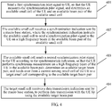
- the inter-small cell handover method is applied to the high frequency network architecture shown in FIG. 1 . Referring to FIG. 2 , the method may include the following steps.
- the UE performs synchronous measurement, to determine a set of small cells available for the UE.
- the UE may perform synchronous measurement upon being powered on, to determine the set of small cells available for the UE while a serving small cell of the UE is determined; or may perform synchronous measurement when a user requests to establish a connection, to determine a serving small cell of the UE and the set of small cells available for the UE; or may periodically perform synchronous measurement while the UE receives high frequency data sent by a serving small cell, to determine the set of small cells available for the UE.
- the signal strength may be a measured RSRP (reference signal received power) value of a reference signal of a current neighboring small cell or a measured RSRQ (Reference Signal Received Quality) value of a reference signal of a current neighboring small cell.
- RSRP reference signal received power
- RSRQ Reference Signal Received Quality
- the UE determines the small cell 1 as the serving small cell of the UE, determines that available small cells in the set of available small cells are the small cell 2 and the small cell 3, determines that an available beam pair corresponding to the small cell 2 is (a high frequency beam 2 of the UE, a high frequency beam 4 of the small cell 2), and determines that an available beam pair corresponding to the small cell 3 is (a high frequency beam 3 of the UE, a high frequency beam 6 of the small cell 3).
- the UE sends the set of available small cells to the macro base station.
- the UE may send the set of available small cells to the macro base station by using a low frequency channel, so that the macro base station identifies the UE according to information about whether the received set of available small cells includes an available small cell.
- the UE is identified as a user that can hand over between small cells, so as to initiate the inter-small cell handover process in the present invention when the UE is in the coverage hole of the serving small cell. If no available small cell is included, the UE is considered by default as or is identified as a user that cannot hand over between small cells.
- the UE When the UE is in a coverage hole of a current serving small cell, receive a first synchronization indication sent by the macro base station.
- the first synchronization indication is used to instruct the UE to perform synchronous measurement on the high frequency beam of the UE in each available beam pair.
- the UE may receive, on a low frequency channel, the first synchronization indication sent by the macro base station.
- the first synchronization indication is used to instruct the UE to separately receive, on the high frequency beam 2 and the high frequency beam 3 of the UE, a synchronization pilot signal sent by a small cell, to perform synchronous measurement.
- the UE performs synchronous measurement according to the first synchronization indication, to select an available target beam pair.
- the available target beam pair is a beam pair having a good channel quality and meeting a high frequency data transmission requirement.
- the UE may use the following method to select the available target beam pair:
- the UE uses an existing inter-small cell handover method to perform synchronous measurement on all beams of all small cells, to select an optimal beam pair.
- the preset threshold is set as required, and is not limited in this embodiment of the present invention. If a signal strength of a synchronization pilot signal is greater than or equal to the preset threshold, it indicates that quality of a channel on which the synchronization pilot signal is sent and received meets a requirement of a high frequency data transmission channel in the high frequency network architecture.
- a signal strength of a synchronization pilot signal is less than the preset threshold, it indicates that quality of a channel on which the synchronization pilot signal is sent and received cannot meet a requirement of a high frequency data transmission channel in the high frequency network architecture, and the channel is an unavailable high frequency transmission channel.
- the UE when the UE in FIG. 1 is in the coverage hole of the serving small cell, the UE needs to perform synchronous measurement only on the available beam pairs (the high frequency beam 2 of the UE, the high frequency beam 4 of the small cell 2) and (the high frequency beam 3 of the UE, the high frequency beam 6 of the small cell 3), to select an available target beam pair from the two beam pairs, that is, an optimal beam pair can be determined as long as synchronous measurement is performed twice.
- this greatly reduces a quantity of times of synchronous measurement, and reduces a synchronous measurement time. Therefore, a time is saved for a small cell handover of the UE in step 205, a delay of re-accessing a high frequency network by the UE is reduced, and QoS of receiving a high frequency service by the UE is improved.
- the UE hands over to a target small cell corresponding to the available target beam pair. Further, the method further includes:
- UE performs synchronous measurement, to determine a set of small cells available for the UE; sends the set of available small cells to a macro base station; when the UE is in a coverage hole of a current serving small cell, performs synchronous measurement according to a first synchronization indication, to select an available target beam pair; and hands over to a target small cell corresponding to the available target beam pair.
- the UE when the UE is in the coverage hole of the serving small cell, as long as the UE performs synchronous measurement on each available beam pair in the set of available small cells determined by the UE, the UE can select an optimal small cell and beam pair, access the selected small cell, and continuously perform high frequency data transmission by using the selected beam pair, thereby reducing a synchronous measurement time, further reducing a delay of re-accessing a high frequency network by the UE, improving QoS of receiving a high frequency service by the UE, and avoiding a problem in the prior art that the UE needs to perform synchronous measurement on all beam pairs of all small cells, and a synchronous measurement time is long, causing a relatively large delay of re-accessing a high frequency network by the UE, and relatively poor QoS of receiving a high frequency service by the UE.
- an embodiment of the present invention further provides an inter-small cell handover method. As shown in FIG. 3 , the method may include the following steps.
- a macro base station receives a set of available small cells sent by UE.
- the set of available small cells includes at least one available small cell, and an available beam pair of each available small cell, and the available beam pair consists of a high frequency beam of the UE and a high frequency beam of the available small cell.
- the macro base station receives a coverage hole status indication sent by a serving small cell of the UE.
- the coverage hole status indication is used to indicate whether the UE is in a coverage hole of the serving small cell.
- the macro base station may receive, on a low frequency channel, the coverage hole status indication sent by the serving small cell.
- the macro base station sends a first synchronization indication to the UE, and separately sends a second synchronization indication to each available small cell in the set of available small cells, so that the UE performs synchronous measurement according to the first synchronization indication, to select an available target beam pair.
- the first synchronization indication is used to instruct the UE to perform synchronous measurement on the high frequency beam of the UE in each available beam pair.
- the second synchronization indication is used to instruct the available small cell to send a synchronization pilot signal to the UE on the high frequency beam in the available beam pair of the available small cell.
- the method further includes:
- the method may further include:
- the macro base station first sends, in a multicast form to each small cell in the set of available small cells by means of data transmission, the data requested by the UE, so that after receiving the handover result, the macro base station directly commands the target small cell to perform data transmission to the UE, rather than transmitting, to the target small cell after the handover result is received, the data requested by the UE, to enable the target small cell to perform data transmission to the UE.
- a macro base station receives a set of available small cells sent by UE and a coverage hole status indication sent by a current serving small cell of the UE, when the UE is in a coverage hole of the current serving small cell, the macro base station sends a first synchronization indication to the UE, and separately sends a second synchronization indication to each available small cell in the set of available small cells, so that the UE performs synchronous measurement according to the first synchronization indication, to select an available target beam pair.
- the first synchronization indication is used to instruct the UE to perform synchronous measurement on a high frequency beam of the UE in each available beam pair
- the second synchronization indication is used to instruct the available small cell to send a synchronization pilot signal to the UE on a high frequency beam in the available beam pair of the available small cell.
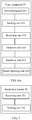
- an embodiment of the present invention further provides an inter-small cell handover method. As shown in FIG. 4 , the method may include the following steps.
- the available beam pair consists of a high frequency beam of the available small cell and a high frequency beam of the UE.
- the available small cell receives a synchronization indication sent by a macro base station, where the synchronization indication instructs the available small cell to send a synchronization pilot signal to the UE on a high frequency beam in the available beam pair of the available small cell.
- the available small cell sends a second synchronization pilot signal to the UE according to the synchronization indication, so that the UE performs synchronous measurement on a high frequency beam of the UE in the available beam pair, determines an available target beam pair, and hands over from a current serving small cell of the UE to a target small cell corresponding to the available target beam pair.
- the target small cell receives a data transmission indication sent by the macro base station, to perform data transmission with the UE by using the available target beam pair.
- the method further includes: receiving, by the available small cell, data that is sent by the macro base station in a multicast form and that the UE requests to transmit.
- the method further includes:
- whether the UE is in the coverage hole of the serving small cell may be determined by using any one of the following three methods (1), (2), or (3):
- a first synchronization pilot signal is sent to UE, so that the UE measures the synchronization pilot signal, and determines an available small cell of the UE and an available beam pair of the available small cell, where the available beam pair consists of a high frequency beam of the available small cell and a high frequency beam of the UE;
- the available small cell receives a synchronization indication sent by a macro base station, where the synchronization indication instructs the available small cell to send a synchronization pilot signal to the UE on the high frequency beam in the available beam pair of the available small cell;
- the available small cell sends a second synchronization pilot signal to the UE according to the synchronization indication, so that the UE performs synchronous measurement on the high frequency beam of the UE in the available beam pair, determines an available target beam pair, and hands over from a current serving small cell of the UE to a target small cell corresponding to the available target
- a current serving small cell of UE is a small cell 1
- a set of available small cells includes a small cell 2 and a small cell 3
- a determined target small cell is the small cell 2.
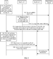
- FIG. 5 is a flowchart of an inter-small cell handover method according to an embodiment of the present invention. As shown in FIG. 5 , the method may include the following steps.
- UE performs synchronous measurement, to determine a set of small cells available for the UE.
- the set of available small cells includes a small cell 2, a small cell 3, an available beam pair (a high frequency beam 2 of the UE, a high frequency beam 4 of the small cell 2) of the small cell 2, and an available beam pair (a high frequency beam 3 of the UE, a high frequency beam 6 of the small cell 3) of the small cell 3.
- the UE sends the set of available small cells to a macro base station.
- a small cell 1 determines that the UE is in a coverage hole of a serving small cell.
- the small cell 1 may determine, by using any one of the following three methods (1), (2), or (3), that the UE is in the coverage hole of the serving small cell:
- the small cell 1 sends a coverage hole status indication to the macro base station.
- the macro base station sends a first synchronization indication to the UE, and separately sends a second synchronization indication to each available small cell in the set of available small cells.
- the first synchronization indication is used to instruct the UE to separately perform synchronous measurement on the high frequency beam of the UE in each available beam pair.
- the second synchronization indication is used to instruct the available small cell to send a synchronization pilot signal to the UE on the high frequency beam in the available beam pair of the available small cell.
- the UE performs synchronous measurement according to the first synchronization indication, to select an available target beam pair (a high frequency beam 2 of the UE, a high frequency beam 4 of a small cell 2).
- the UE hands over to the small cell 2: a target small cell corresponding to the available target beam pair.
- the UE sends a handover result to the macro base station.
- the macro base station sends indication information to the small cell 2 according to the handover result, where the indication information is used to instruct the small cell 2 to transmit high frequency data with the UE by using the available target beam pair.
- UE performs synchronous measurement, determines a set of small cells available for the UE, and sends the set of available small cells to a macro base station; when determining that the UE is in a coverage hole of a serving small cell, the serving small cell sends a coverage hole status indication to the macro base station; the macro base station sends a first synchronization indication to the UE, and separately sends a second synchronization indication to an available small cell in the set of available small cells; the UE performs synchronous measurement, selects a target beam pair, hands over to a target small cell corresponding to the target beam pair, and sends a handover result to the macro base station; the macro base station instructs the target small cell to transmit high frequency data to the UE.
- the UE when the UE is in the coverage hole of the serving small cell, as long as the UE performs synchronous measurement on each available beam pair in the set of available small cells determined by the UE, the UE can select an optimal target small cell and target beam pair, and hands over to the target small cell, thereby reducing a delay of re-accessing a high frequency network by the UE, improving QoS of receiving a high frequency service by the UE, and avoiding a problem in the prior art that the UE needs to perform synchronous measurement on all beam pairs of all small cells, and a synchronous measurement time is long, causing a relatively large delay of re-accessing a high frequency network by the UE, and relatively poor QoS of receiving a high frequency service by the UE.
- an embodiment of the present invention further provides user equipment 60.
- the user equipment 60 may include:
- determining unit 601 is specifically configured to:
- the signal strength may be a measured RSRP value of a reference signal of a current neighboring small cell or a measured RSRQ value of a reference signal of a current neighboring small cell.
- the UE determines the small cell 1 as the serving small cell of the UE, determines that available small cells in the set of available small cells are the small cell 2 and the small cell 3, determines that an available beam pair corresponding to the small cell 2 is (a high frequency beam 2 of the UE, a high frequency beam 4 of the small cell 2), and determines that an available beam pair corresponding to the small cell 3 is (a high frequency beam 3 of the UE, a high frequency beam 6 of the small cell 3).
- selection unit 604 is specifically configured to:
- the preset threshold is set as required, and is not limited in this embodiment of the present invention. If a signal strength of a synchronization pilot signal is greater than or equal to the preset threshold, it indicates that quality of a channel on which the synchronization pilot signal is sent and received meets a requirement of a high frequency data transmission channel in the high frequency network architecture. If a signal strength of a synchronization pilot signal is less than the preset threshold, it indicates that quality of a channel on which the synchronization pilot signal is sent and received cannot meet a requirement of a high frequency data transmission channel in the high frequency network architecture, and the channel is an unavailable high frequency transmission channel.
- the UE when the UE in FIG. 1 is in the coverage hole of the serving small cell, the UE needs to perform synchronous measurement only on the available beam pairs (the high frequency beam 2 of the UE, the high frequency beam 4 of the small cell 2) and (the high frequency beam 3 of the UE, the high frequency beam 6 of the small cell 3), to select an available target beam pair from the two beam pairs, that is, an optimal beam pair can be determined as long as synchronous measurement is performed twice.
- this greatly reduces a quantity of times of synchronous measurement, and reduces a synchronous measurement time. Therefore, a time is saved for a small cell handover of the UE, a delay of re-accessing a high frequency network by the UE is reduced, and QoS of receiving a high frequency service by the UE is improved.
- the user equipment further includes:
- the user equipment 60 provided in this embodiment of the present invention first performs synchronous measurement, to determine a set of small cells available for the UE; sends the set of available small cells to a macro base station; when the UE is in a coverage hole of a serving small cell, receives a first synchronization indication sent by the macro base station; performs synchronous measurement according to the first synchronization indication, to select an available target beam pair; and hands over to a target small cell corresponding to the available target beam pair.
- the UE when the UE is in the coverage hole of the serving small cell, as long as the UE performs synchronous measurement on each available beam pair in the set of available small cells determined by the UE, the UE can select an optimal target small cell and target beam pair, and hands over to the target small cell, thereby reducing a delay of re-accessing a high frequency network by the UE, improving QoS of receiving a high frequency service by the UE, and avoiding a problem in the prior art that the UE needs to perform synchronous measurement on all beam pairs of all small cells, and a synchronous measurement time is long, causing a relatively large delay of re-accessing a high frequency network by the UE, and relatively poor QoS of receiving a high frequency service by the UE.
- an embodiment of the present invention further provides a macro base station 70.
- the macro base station 70 may include:
- the receiving unit 701 is further configured to receive a handover result sent by the UE, where the handover result includes the available target beam pair and a cell identifier of the target small cell; and correspondingly, as shown in FIG. 7A , the macro base station further includes: an indication unit 703, configured to: instruct, according to the handover result, to perform data transmission between the target small cell and the UE by using the available target beam pair, and instruct the serving small cell to terminate data transmission with the UE. Further, to ensure that the UE receives, as quickly as possible when the UE is in the coverage hole of the serving small cell, data transmitted by another small cell on a high frequency channel, and reduces a connection delay of a high frequency data service, as shown in FIG. 7B , the macro base station further includes:
- the macro base station before synchronous measurement is performed on a UE side to determine the available target beam pair, the macro base station first sends, in a multicast form to each small cell in the set of available small cells, the data requested by the UE, so that after receiving the handover result, the macro base station directly commands the target small cell to perform data transmission to the UE, avoiding a waste of time caused by that the data requested by the UE is transmitted to the target small cell by the macro base station only after the handover result is received, to enable the target small cell to perform data transmission to the UE.
- the macro base station 70 receives a set of available small cells sent by UE, and after receiving a coverage hole status indication sent by a serving small cell, the macro base station sends a first synchronization indication to the UE, and separately sends a second synchronization indication to each available small cell in the set of available small cells, so that the UE performs synchronous measurement according to the first synchronization indication, to select an available target beam pair.
- the first synchronization indication is used to instruct the UE to perform synchronous measurement on a high frequency beam of the UE in each available beam pair
- the second synchronization indication is used to instruct the available small cell to send a synchronization pilot signal to the UE on a high frequency beam in the available beam pair of the available small cell.
- an embodiment of the present invention provides a small cell 80.
- the small cell 80 includes: a sending unit 801, a receiving unit 802, and a data communications unit 803.
- the sending unit 801 is configured to send a first synchronization pilot signal to UE, so that the UE measures the synchronization pilot signal, and determines an available small cell of the UE and an available beam pair of the available small cell.
- the available beam pair consists of a high frequency beam of the available small cell and a high frequency beam of the UE.
- the receiving unit 802 is configured to receive a synchronization indication sent by a macro base station, where the synchronization indication instructs the available small cell to send a synchronization pilot signal to the UE on the high frequency beam in the available beam pair of the available small cell.
- the sending unit 801 is further configured to send a second synchronization pilot signal to the UE according to the synchronization indication, so that the UE performs synchronous measurement on the high frequency beam of the UE in the available beam pair, determines an available target beam pair, and hands over from a current serving small cell of the UE to a target small cell corresponding to the available target beam pair.
- the receiving unit 802 is further configured to receive a data transmission indication sent by the macro base station.
- the data communications unit 803 is configured to perform data transmission with the UE by using the available target beam pair.
- the receiving unit 802 is further configured to: before the receiving unit receives the data transmission indication sent by the macro base station, receive data that is sent by the macro base station in a multicast form and that the UE requests to transmit.
- the small cell 80 when the small cell 80 is the current serving small cell of the UE, as shown in FIG. 8A , the small cell 80 further includes:
- determining unit 804 is specifically configured to:
- an embodiment of the present invention provides an inter-small cell handover system 90.
- the inter-small cell handover system 90 may include user equipment 60, a macro base station 70, at least one serving small cell 80, and at least one available small cell 0, where the user equipment 60, the macro base station 70, and the small cell 80 are respectively the same as the user equipment 60, the macro base station 70, and the small cell 80 that are in the foregoing, and are not described herein again.
- the UE 60 performs synchronous measurement, determines a set of small cells available for the UE 60, and sends the set of available small cells to the macro base station 70; when determining that the UE is in a coverage hole of a serving small cell, the small cell 80 sends a coverage hole status indication to the macro base station 70; the macro base station 70 sends a first synchronization indication to the UE, and sends a second synchronization indication to an available small cell in the set of available small cells; the UE 60 performs synchronous measurement, determines an available target beam pair, and hands over to a target small cell corresponding to the available target beam pair.
- the UE when the UE is in the coverage hole of the serving small cell, as long as the UE performs synchronous measurement on each available beam pair in the set of available small cells determined by the UE, the UE can select an optimal target small cell and target beam pair, and hands over to the target small cell, thereby reducing a delay of re-accessing a high frequency network by the UE, improving QoS of receiving a high frequency service by the UE, and avoiding a problem in the prior art that the UE needs to perform synchronous measurement on all beam pairs of all small cells, and a synchronous measurement time is long, causing a relatively large delay of re-accessing a high frequency network by the UE, and relatively poor QoS of receiving a high frequency service by the UE.
- an embodiment of the present invention further provides user equipment 100.
- the user equipment 100 may include: a communications unit 1001, a processor 1002, a memory 1003, and at least one communications bus 1004, which is configured to implement a connection and mutual communication between these apparatuses.
- the processor 1002 may be a central processing unit (CPU for short).
- the memory 1003 may be a volatile memory, such as a random-access memory (RAM for short); or a non-volatile memory, such as a read-only memory (ROM for short), a flash memory, a hard disk drive (HDD for short) or a solid-state drive (SSD for short); or a combination of the foregoing types of memories; and provides instructions and data for the processor 1002.
- RAM random-access memory
- ROM read-only memory
- flash memory such as a flash memory, a hard disk drive (HDD for short) or a solid-state drive (SSD for short
- SSD solid-state drive
- the processor 1002 is configured to perform synchronous measurement, to determine a set of small cells available for the UE.
- the set of available small cells includes at least one available small cell, and an available beam pair of each available small cell, and the available beam pair consists of a high frequency beam of the UE and a high frequency beam of the available small cell.
- the communications unit 1001 is configured to: send the set of available small cells to a macro base station; and when the UE is in a coverage hole of a current serving small cell, receive a first synchronization indication sent by the macro base station.
- the first synchronization indication is used to instruct the UE to perform synchronous measurement on the high frequency beam of the UE in each available beam pair.
- the processor 1002 is further configured to perform synchronous measurement according to the first synchronization indication, to select an available target beam pair; and hand over to a target small cell corresponding to the available target beam pair. Further, the processor 1002 is specifically configured to:
- the signal strength may be a measured RSRP value of a reference signal of a current neighboring small cell or a measured RSRQ value of a reference signal of a current neighboring small cell.
- the UE determines the small cell 1 as the serving small cell of the UE, determines that available small cells in the set of available small cells are the small cell 2 and the small cell 3, determines that an available beam pair corresponding to the small cell 2 is (a high frequency beam 2 of the UE, a high frequency beam 4 of the small cell 2), and determines that an available beam pair corresponding to the small cell 3 is (a high frequency beam 3 of the UE, a high frequency beam 6 of the small cell 3).
- processor 1002 is specifically configured to:
- the preset threshold is set as required, and is not limited in this embodiment of the present invention. If a signal strength of a synchronization pilot signal is greater than or equal to the preset threshold, it indicates that quality of a channel on which the synchronization pilot signal is sent and received meets a requirement of a high frequency data transmission channel in the high frequency network architecture. If a signal strength of a synchronization pilot signal is less than the preset threshold, it indicates that quality of a channel on which the synchronization pilot signal is sent and received cannot meet a requirement of a high frequency data transmission channel in the high frequency network architecture, and the channel is an unavailable high frequency transmission channel.
- the UE when the UE in FIG. 1 is in the coverage hole of the serving small cell, the UE needs to perform synchronous measurement only on the available beam pairs (the high frequency beam 2 of the UE, the high frequency beam 4 of the small cell 2) and (the high frequency beam 3 of the UE, the high frequency beam 6 of the small cell 3), to select an available target beam pair from the two beam pairs, that is, an optimal beam pair can be determined as long as synchronous measurement is performed twice.
- this greatly reduces a quantity of times of synchronous measurement, and reduces a synchronous measurement time. Therefore, a time is saved for a small cell handover of the UE, a delay of re-accessing a high frequency network by the UE is reduced, and QoS of receiving a high frequency service by the UE is improved.
- the communications unit 1001 is further configured to: send a handover result to the macro base station, so that the macro base station instructs, according to the handover result, to perform data transmission between the target small cell and the UE by using the available target beam pair, and instructs the serving small cell to terminate data transmission with the UE, where the handover result includes the available target beam pair and a cell identifier of the target small cell; and receive a data transmission indication sent by the macro base station, to perform data transmission with the target small cell by using the available target beam pair, where the data transmission indication is used to instruct to perform data transmission between the target small cell and the UE by using the available target beam pair.
- the user equipment 100 provided in this embodiment of the present invention first performs synchronous measurement, to determine a set of small cells available for the UE; sends the set of available small cells to a macro base station; when the UE is in a coverage hole of a serving small cell, receives a first synchronization indication sent by the macro base station; performs synchronous measurement according to the first synchronization indication, to select an available target beam pair; and hands over to a target small cell corresponding to the available target beam pair.
- the UE when the UE is in the coverage hole of the serving small cell, as long as the UE performs synchronous measurement on each available beam pair in the set of available small cells determined by the UE, the UE can select an optimal small cell and beam pair, access the selected small cell, and continuously perform high frequency data transmission by using the selected beam pair, thereby reducing a synchronous measurement time, further reducing a delay of re-accessing a high frequency network by the UE, improving QoS of receiving a high frequency service by the UE, and avoiding a problem in the prior art that the UE needs to perform synchronous measurement on all beam pairs of all small cells, and a synchronous measurement time is long, causing a relatively large delay of re-accessing a high frequency network by the UE, and relatively poor QoS of receiving a high frequency service by the UE.
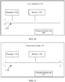
- an embodiment of the present invention further provides a macro base station 110.
- the macro base station 110 may include: a communications unit 1101, a processor 1102, a memory 1103, and at least one communications bus 1104, which is configured to implement a connection and mutual communication between these apparatuses.
- the processor 1102 may be a central processing unit (CPU for short).
- the memory 1103 may be a volatile memory, such as a random-access memory (RAM for short); or a non-volatile memory, such as a read-only memory (ROM for short), a flash memory, a hard disk drive (HDD for short) or a solid-state drive (SSD for short); or a combination of the foregoing types of memories; and provides instructions and data for the processor 1102.
- RAM random-access memory
- ROM read-only memory
- flash memory such as a flash memory, a hard disk drive (HDD for short) or a solid-state drive (SSD for short
- SSD solid-state drive
- the communications unit 1101 is configured to: receive a set of available small cells sent by UE, where the set of available small cells includes at least one available small cell, and an available beam pair of each available small cell, and the available beam pair consists of a high frequency beam of the UE and a high frequency beam of the available small cell; receive a coverage hole status indication sent by a serving small cell of the UE, where the coverage hole status indication is used to indicate that the UE is in a coverage hole of the serving small cell; and send a first synchronization indication to the UE, and separately send a second synchronization indication to each available small cell in the set of available small cells, so that the UE performs synchronous measurement according to the first synchronization indication, to select an available target beam pair, where the first synchronization indication is used to instruct the UE to perform synchronous measurement on the high frequency beam of the UE in each available beam pair, and the second synchronization indication is used to instruct the available small cell to send a synchronization pilot signal to the UE on the high frequency beam in
- the communications unit 1101 is further configured to receive a handover result sent by the UE, where the handover result includes the available target beam pair and a cell identifier of the target small cell; and correspondingly, the processor 1102 is configured to: instruct, according to the handover result, to perform data transmission between the target small cell and the UE by using the available target beam pair, and instruct the serving small cell to terminate data transmission with the UE.
- the processor 1102 is further configured to: before the indication unit instructs, according to the handover result, to perform data transmission between the target small cell and the UE by using the available target beam pair, group, into one group, an available small cell that is in the set of available small cells and that is in a same coverage area of the macro base station; and the communications unit 1101 is further configured to: after the macro base station receives a coverage hole status indication sent by the serving small cell of the UE, separately send, in a multicast form to each group of available small cells, data that the UE requests to transmit.
- the macro base station before synchronous measurement is performed on a UE side to determine the available target beam pair, the macro base station first sends, in a multicast form to each small cell in the set of available small cells, the data requested by the UE, so that after receiving the handover result, the macro base station directly commands the target small cell to perform data transmission to the UE, avoiding a waste of time caused by that the data requested by the UE is transmitted to the target small cell by the macro base station only after the handover result is received, to enable the target small cell to perform data transmission to the UE.
- the macro base station 110 receives a set of available small cells sent by UE, and after receiving a coverage hole status indication sent by a serving small cell, the macro base station sends a first synchronization indication to the UE, and separately sends a second synchronization indication to each available small cell in the set of available small cells, so that the UE performs synchronous measurement according to the first synchronization indication, to select an available target beam pair.
- the first synchronization indication is used to instruct the UE to perform synchronous measurement on a high frequency beam of the UE in each available beam pair
- the second synchronization indication is used to instruct the available small cell to send a synchronization pilot signal to the UE on a high frequency beam in the available beam pair of the available small cell.
- an embodiment of the present invention further provides a small cell 120.
- the small cell 120 may include: a communications unit 1201, a processor 1202, a memory 1203, and at least one communications bus 1204, which is configured to implement a connection and mutual communication between these apparatuses.
- the processor 1202 may be a central processing unit (CPU for short).
- the memory 1203 may be a volatile memory, such as a random-access memory (RAM for short); or a non-volatile memory, such as a read-only memory (ROM for short), a flash memory, a hard disk drive (HDD for short) or a solid-state drive (SSD for short); or a combination of the foregoing types of memories; and provides instructions and data for the processor 1202.
- RAM random-access memory
- ROM read-only memory
- flash memory such as a flash memory, a hard disk drive (HDD for short) or a solid-state drive (SSD for short
- SSD solid-state drive
- the processor 1202 is configured to determine that UE is in a coverage hole of a serving small cell.
- the communications unit 1201 sends a first synchronization pilot signal to the UE, so that the UE measures the synchronization pilot signal, and determines an available small cell of the UE and an available beam pair of the available small cell.
- the available beam pair consists of a high frequency beam of the available small cell and a high frequency beam of the UE.
- the communications unit 1201 is further configured to: receive a synchronization indication sent by a macro base station, where the synchronization indication instructs the available small cell to send a synchronization pilot signal to the UE on the high frequency beam in the available beam pair of the available small cell; send a second synchronization pilot signal to the UE according to the synchronization indication, so that the UE performs synchronous measurement on the high frequency beam of the UE in the available beam pair, determines an available target beam pair, and hands over from a current serving small cell of the UE to a target small cell corresponding to the available target beam pair; receive a data transmission indication sent by the macro base station; and perform data transmission with the UE by using the available target beam pair. Further, the communications unit 1201 is further configured to: before the receiving unit receives the data transmission indication sent by the macro base station, receive data that is sent by the macro base station in a multicast form and that the UE requests to transmit.
- the processor 1202 is configured to determine whether the UE is in a coverage hole of the current serving small cell; and the communications unit 1201 is further configured to: send a coverage hole status indication to the macro base station, where the coverage hole status indication is used to indicate whether the UE is in the coverage hole of the small cell; and when the UE is in the coverage hole of the current serving small cell, receive, by the small cell, indication information sent by the macro base station, to terminate data transmission with the UE.
- processor 1202 is specifically configured to:
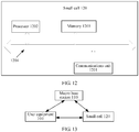
- an embodiment of the present invention provides an inter-small cell handover system 130.
- the inter-small cell handover system 130 may include user equipment 100, a macro base station 110, and at least one small cell 120, where the user equipment 100, the macro base station 110, and the small cell 120 are respectively the same as the user equipment 100, the macro base station 110, and the small cell 120 that are in the foregoing, and are not described herein again.
- the UE 100 performs synchronous measurement, determines a set of small cells available for the UE 100, and sends the set of available small cells to the macro base station 110; when determining that the UE is in a coverage hole of a serving small cell, the small cell 120 sends a coverage hole status indication to the macro base station 110; the macro base station 110 sends a first synchronization indication to the UE, and separately sends a second synchronization indication to an available small cell in the set of available small cells; the UE 100 performs synchronous measurement, determines an available target beam pair, and hands over to a target small cell corresponding to the available target beam pair.
- the UE when the UE is in the coverage hole of the serving small cell, as long as the UE performs synchronous measurement on each available beam pair in the set of available small cells determined by the UE, the UE can select an optimal small cell and beam pair, access the selected small cell, and continuously perform high frequency data transmission by using the selected beam pair, thereby reducing a synchronous measurement time, further reducing a delay of re-accessing a high frequency network by the UE, improving QoS of receiving a high frequency service by the UE, and avoiding a problem in the prior art that the UE needs to perform synchronous measurement on all beam pairs of all small cells, and a synchronous measurement time is long, causing a relatively large delay of re-accessing a high frequency network by the UE, and relatively poor QoS of receiving a high frequency service by the UE.
- the disclosed system, mobile terminal, and method may be implemented in other manners.
- the described mobile terminal embodiment is merely an example.
- the unit division is merely logical function division and may be other division in actual implementation.
- a plurality of units or components may be combined or integrated into another system, or some features may be ignored or not performed.
- the displayed or discussed mutual couplings or direct couplings or communication connections may be implemented through some interfaces.
- the indirect couplings or communication connections between the mobile terminals or units may be implemented in electronic, mechanical, or other forms.
- the units described as separate parts may or may not be physically separate, and parts displayed as units may or may not be physical units, may be located in one position, or may be distributed on a plurality of network units. Some or all of the units may be selected according to actual needs to achieve the objectives of the solutions of the embodiments.
- functional units in the embodiments of the present invention may be integrated into one processing unit, or each of the units may exist alone physically, or two or more units are integrated into one unit.
- the integrated unit may be implemented in a form of hardware, or may be implemented in a form of hardware in addition to a software functional unit.
- the integrated unit may be stored in a computer-readable storage medium.
- the software functional unit is stored in a storage medium and includes several instructions for instructing a computer device (which may be a personal computer, a server, or a network device) to perform some of the steps of the methods described in the embodiments of the present invention.
- the foregoing storage medium includes: any medium that can store program code, such as a USB flash drive, a removable hard disk, a read-only memory (ROM for short), a random access memory (RAM for short), a magnetic disk, or an optical disc.
Landscapes
- Engineering & Computer Science (AREA)
- Signal Processing (AREA)
- Computer Networks & Wireless Communication (AREA)
- Mobile Radio Communication Systems (AREA)
Claims (23)
- Verfahren zum Umschalten zwischen kleinen Zellen, umfassend:Durchführen (201, 501) durch ein Benutzergerät, UE, einer Synchronmessung eines Pilotsignals, um einen Satz kleiner Zellen, die dem UE zur Verfügung stehen, zu bestimmen, wobei der Satz verfügbarer kleiner Zellen zumindest eine verfügbare kleine Zelle und ein verfügbares Strahlenpaar jeder verfügbaren kleinen Zelle umfasst und das verfügbare Strahlenpaar aus einem Hochfrequenzstrahl des UE und einem Hochfrequenzstrahl der verfügbaren kleinen Zelle besteht;Senden (202, 502) durch das UE des Satzes verfügbarer kleiner Zellen an eine Makrobasisstation;wenn sich das UE in einem Versorgungsloch einer aktuellen bedienenden kleinen Zelle befindet, Empfangen (203, 505) einer ersten Synchronisierungsangabe, die durch die Makrobasisstation gesendet wird, wobei die erste Synchronisierungsangabe zum Anweisen des UE verwendet wird, eine Synchronmessung auf dem Hochfrequenzstrahl des UE in jedem verfügbaren Strahlenpaar durchzuführen;Durchführen (204, 506) durch das UE einer Synchronmessung eines Pilotsignals gemäß der ersten Synchronisierungsangabe, um ein verfügbares Zielstrahlenpaar auszuwählen;Umschalten (205, 507) durch das UE zu einer kleinen Zielzelle entsprechend dem verfügbaren Zielstrahlenpaar; undDurchführen durch das UE einer Datenübertragung mit der kleinen Zielzelle unter Verwendung des verfügbaren Zielstrahlenpaars.
- Verfahren zum Umschalten zwischen kleinen Zellen nach Anspruch 1, wobei das Durchführen durch das UE einer Synchronmessung um einen Satz kleiner Zellen, die dem UE zur Verfügung stehen, zu bestimmen, umfasst:Senden durch das UE einer Synchronmessungsanfrage an die Makrobasisstation, sodass die Makrobasisstation alle kleinen Zellen in einem Versorgungsbereich der Makrobasisstation anweist, Synchronisierungspilotsignale an das UE zu senden;getrennt Empfangen durch das UE auf jedem Hochfrequenzstrahl des UE des Synchronisierungspilotsignals, das durch alle kleinen Zellen auf jedem Hochfrequenzstrahl der kleinen Zellen gesendet wird;getrennt Messen durch das UE einer Signalstärke jedes Synchronisierungspilotsignals und Sortieren der Signalstärken in absteigender Reihenfolge; undBestimmen durch das UE einer kleinen Zelle, die ein Synchronisierungspilotsignal mit einer höchsten Signalstärke sendet, als eine bedienende Zelle des UE; undBestimmen zumindest einer kleinen Zelle, die ein Synchronisierungspilotsignal mit einer zweithöchsten Signalstärke sendet, als eine verfügbare kleine Zelle in dem Satz von kleinen Zellen, die dem UE zur Verfügung stehen.
- Verfahren zum Umschalten zwischen kleinen Zellen nach Anspruch 1 oder 2, wobei das Durchführen durch das UE einer Synchronmessung gemäß der ersten Synchronisierungsangabe, um ein verfügbares Zielstrahlenpaar auszuwählen, umfasst:Messen durch das UE einer Signalstärke eines Synchronisierungspilotsignals auf dem Hochfrequenzstrahl des UE in jedem verfügbaren Strahlenpaar; undfalls die Signalstärke, die dem Synchronisierungspilotsignal mit der höchsten Signalstärke entspricht, größer oder gleich einem voreingestellten Schwellenwert ist, Auswählen eines Strahlenpaars, das aus einem Hochfrequenzstrahl des UE, auf dem das Synchronisierungspilotsignal mit der höchsten Signalstärke empfangen wird, und einem Hochfrequenzstrahl einer verfügbaren kleinen Zelle, die das Synchronisierungspilotsignal mit der höchsten Signalstärke sendet, besteht, als das verfügbare Zielstrahlenpaar.
- Verfahren zum Umschalten zwischen kleinen Zellen nach einem der Ansprüche 1 bis 3, wobei das Verfahren ferner umfasst:Senden (508) durch das UE eines Umschaltergebnisses an die Makrobasisstation, sodass die Makrobasisstation gemäß dem Umschaltergebnis eine Durchführung einer Datenübertragung zwischen der kleinen Zielzelle und dem UE unter Verwendung des verfügbaren Zielstrahlenpaars anweist und die bedienende kleine Zelle anweist, eine Datenübertragung mit dem UE zu beenden, wobei das Umschaltergebnis das verfügbare Zielstrahlenpaar und eine Zellenkennung der kleinen Zielzelle umfasst; undEmpfangen (509) einer Datenübertragungsangabe, die durch die Makrobasisstation gesendet wird, um eine Datenübertragung mit der kleinen Zielzelle unter Verwendung des verfügbaren Zielstrahlenpaars durchzuführen, wobei die Datenübertragungsangabe wird, eine Durchführung der Datenübertragung zwischen der kleinen Zielzelle und dem UE unter Verwendung des verfügbaren Zielstrahlenpaars anzuweisen.
- Verfahren zum Umschalten zwischen kleinen Zellen, umfassend:Empfangen (301, 502) durch eine Makrostation eines Satzes kleiner Zellen, die dem Benutzergerät, UE, zur Verfügung stehen, der durch das UE gesendet wird, wobei der Satz verfügbarer kleiner Zellen zumindest eine verfügbare kleine Zelle und ein verfügbares Strahlenpaar jeder verfügbaren kleinen Zelle umfasst und das verfügbare Strahlenpaar aus einem Hochfrequenzstrahl des UE und einem Hochfrequenzstrahl der verfügbaren kleinen Zelle besteht;Empfangen (302, 504) durch die Makrobasisstation einer Versorgungslochstatusangabe, die durch eine aktuelle bedienende kleine Zelle des UE gesendet wird, wobei die Versorgungslochstatusangabe zur Angabe verwendet wird, ob sich das UE in einem Versorgungsloch der aktuellen bedienenden kleinen Zelle befindet;wenn sich das UE im Versorgungsloch der aktuellen bedienenden kleinen Zelle befindet, Senden (303, 505) durch die Makrobasisstation einer ersten Synchronisierungsangabe an das UE und separat Senden einer zweiten Synchronisierungsangabe an jede verfügbare kleine Zelle in dem Satz verfügbarer kleiner Zellen, sodass das UE eine Synchronmessung eines Pilotsignals gemäß der ersten Synchronisierungsangabe durchführt, ein verfügbares Zielstrahlenpaar auswählt und von der aktuellen bedienenden kleinen Zelle des UE zu einer kleinen Zielzelle entsprechend dem verfügbaren Zielstrahlenpaar umschaltet, wobei die erste Synchronisierungsangabe verwendet wird, das UE anzuweisen, eine Synchronmessung des Pilotsignals auf dem Hochfrequenzstrahl des UE in jedem verfügbaren Strahlenpaar durchzuführen, und die zweite Synchronisierungsangabe verwendet wird, die verfügbare kleine Zelle anzuweisen, ein Synchronisierungspilotsignal an das UE auf dem Hochfrequenzstrahl in dem verfügbaren Paar der verfügbare kleinen Zelle zu senden; undSenden (509) durch die Makrobasisstation einer Datenübertragungsangabe an die kleine Zielzelle, um eine Datenübertragung mit dem UE unter Verwendung des verfügbaren Zielstrahlenpaars durchzuführen.
- Verfahren zum Umschalten zwischen kleinen Zellen nach Anspruch 5, wobei das Verfahren ferner umfasst:Empfangen durch die Makrobasisstation eines Umschaltergebnisses, das durch das UE gesendet wird, wobei das Umschaltergebnis das verfügbare Zielstrahlenpaar und eine Zellenkennung der kleinen Zielzelle entsprechend dem verfügbaren Zielstrahlenpaar umfasst; undAnweisen durch die Makrobasisstation gemäß dem Umschaltergebnis, eine Datenübertragung zwischen der kleinen Zielzelle und dem UE unter Verwendung des verfügbaren Strahlenpaars durchzuführen, und Anweisen der bedienenden kleinen Zelle, eine Datenübertragung mit dem UE zu beenden.
- Verfahren zum Umschalten zwischen kleinen Zellen nach Anspruch 6, wobei vor dem Anweisen durch die Makrobasisstation gemäß dem Umschaltergebnis, eine Datenübertragung zwischen der kleinen Zielzelle und dem ÜE unter Verwendung des verfügbaren Strahlenpaars durchzuführen, das Verfahren ferner umfasst:Gruppieren durch die Makrobasisstation einer verfügbaren kleinen Zelle, die sich in dem Satz verfügbarer kleiner Zellen befindet und die sich im selben Versorgungsbereich der Makrobasisstation befindet, in eine Gruppe; undnach Empfangen einer Versorgungslochstatusangabe, die durch die bedienende kleine Zelle des UE gesendet wird, getrennt Senden durch die Makrobasisstation von Daten, deren Sendung das UE anfordert, in einer Gruppenrufform an jede Gruppe verfügbarer kleiner Zellen.
- Verfahren zum Umschalten zwischen kleinen Zellen, umfassend:Senden (401) eines ersten Synchronisierungspilotsignals an das Benutzergerät, UE, durch eine verfügbare kleine Zelle, wobei das erste Synchronisierungspilotsignal auf einem Hochfrequenzstrahl der kleinen Zelle gesendet wird, sodass das UE das Synchronisierungspilotsignal misst und eine verfügbare Zelle des UE und ein verfügbares Strahlenpaar der verfügbaren kleinen Zelle bestimmt, wobei das verfügbare Strahlenpaar aus einem Hochfrequenzstrahl der verfügbaren kleinen Zelle und einem Hochfrequenzstrahl des UE besteht;Empfangen (402) durch die verfügbare kleine Zelle einer Synchronisierungsangabe, die durch eine Makrobasisstation gesendet wird, wobei die Synchronisierungsangabe die verfügbare kleine Zelle anweist, ein Synchronisierungspilotsignal an das UE auf dem Hochfrequenzstrahl in dem verfügbaren Strahlenpaar der verfügbaren kleinen Zelle zu senden;Senden (403) durch die verfügbare kleine Zelle eines zweiten Synchronisierungspilotsignals an das UE gemäß der Synchronisierungsangabe, sodass das UE eine Synchronmessung des Pilotsignals auf dem Hochfrequenzstrahl des UE in dem verfügbaren Strahlenpaar durchführt, ein verfügbares Zielstrahlenpaar bestimmt und von einer aktuellen bedienenden kleinen Zelle des UE zu einer kleinen Zielzelle umschaltet, die dem verfügbaren Zielstrahlenpaar entspricht; undEmpfangen (404) durch die verfügbare kleine Zelle einer Datenübertragungsangabe, die durch die Makrobasisstation gesendet wird, um eine Datenübertragung mit dem UE unter Verwendung des verfügbaren Zielstrahlenpaars durchzuführen.
- Verfahren zum Umschalten zwischen kleinen Zellen nach Anspruch 8, wobei vor dem Empfangen durch die verfügbare kleine Zelle einer Datenübertragungsangabe, die durch die Makrobasisstation gesendet wird, das Verfahren ferner umfasst:
Empfangen durch die verfügbare kleine Zelle von Daten, die durch die Makrobasisstation in einer Gruppenform gesendet werden und deren Sendung das UE anfordert. - Verfahren zum Umschalten zwischen kleinen Zellen nach Anspruch 8 oder 9, wobei das Verfahren ferner umfasst:Bestimmen, ob sich das UE in einem Versorgungsloch der aktuellen bedienenden kleinen Zelle befindet;Senden einer Versorgungslochstatusangabe an die Makrobasisstation, wobei die Versorgungslochstatusangabe zur Angabe verwendet wird, ob sich das UE im Versorgungsloch der kleinen Zelle befindet; undwenn sich das UE im Versorgungsloch der aktuellen bedienenden kleinen Zelle befindet, Empfangen durch die aktuelle bedienende kleine Zelle von Angabeinformationen, die durch die Makrobasisstation gesendet werden, um die Datenübertragung mit dem UE zu beenden.
- Verfahren zum Umschalten zwischen kleinen Zellen nach Anspruch 10, wobei der Schritt zum Bestimmen, ob sich das UE in einem Versorgungsloch der kleinen Zelle befindet, umfasst:falls kontinuierlich zumindest zweimal bestimmt wird, dass ein "Uplink" des UE falsch demoduliert wird, Bestimmen, dass sich das UE im Versorgungsloch der aktuellen bedienenden kleinen Zelle befindet; oderfalls ein empfangenes Referenzsignal für empfangene Leistung RSRP oder ein Referenzsignal für empfangene Qualität RSRQ, das durch das UE gesendet wird, kleiner als ein voreingestellter Schwellenwert ist, Bestimmen, dass sich das UE im Versorgungsloch der aktuellen bedienenden kleinen Zelle befindet; oderfalls nicht kontinuierlich zumindest zweimal nach Senden einer Anforderungsnachricht an das UE eine Antwortnachricht des UE empfangen wird, Bestimmen, dass sich das UE im Versorgungsloch der kleinen Zelle befindet.
- Benutzergerät, wobei das Benutzergerät umfasst:eine Bestimmungseinheit (601), die zum Durchführen einer Synchronmessung eines Pilotsignals konfiguriert ist, um einen Satz kleiner Zellen, die dem UE zur Verfügung stehen, zu bestimmen, wobei der Satz verfügbarer kleiner Zellen zumindest eine verfügbare kleine Zelle und ein verfügbares Strahlenpaar jeder verfügbaren kleinen Zelle umfasst und das verfügbare Strahlenpaar aus einem Hochfrequenzstrahl des UE und einem Hochfrequenzstrahl der verfügbaren kleinen Zelle besteht;eine Sendeeinheit (602), die zum Senden des Satzes verfügbarer kleiner Zellen an eine Makrobasisstation konfiguriert ist;eine Empfangseinheit (603), die konfiguriert ist zum: wenn sich das UE in einem Versorgungsloch einer aktuellen bedienenden kleinen Zelle befindet, Empfangen einer ersten Synchronisierungsangabe, die durch die Makrobasisstation gesendet wird, wobei die erste Synchronisierungsangabe zum Anweisen des UE verwendet wird, eine Synchronmessung auf dem Hochfrequenzstrahl des UE in jedem verfügbaren Strahlenpaar durchzuführen;eine Auswahleinheit (604), die zum Durchführen einer Synchronmessung gemäß der ersten Synchronisierungsangabe konfiguriert ist, um ein verfügbares Zielstrahlenpaar auszuwählen;eine Umschalteinheit (605), die zum Umschalten zu einer kleinen Zielzelle entsprechend dem verfügbaren Zielstrahlenpaar konfiguriert ist; unddie Sendeeinheit (602) zum Durchführen einer Datenübertragung mit der kleinen Zielzelle unter Verwendung des verfügbaren Zielstrahlenpaars konfiguriert ist.
- Benutzergerät nach Anspruch 12, wobei die Bestimmungseinheit (601) im Speziellen konfiguriert ist zum:Senden einer Synchronmessungsanfrage an die Makrobasisstation, sodass die Makrobasisstation alle kleinen Zellen in einem Versorgungsbereich der Makrobasisstation anweist, Synchronisierungspilotsignale an das UE zu senden;getrennt Empfangen auf jedem Hochfrequenzstrahl des UE des Synchronisierungspilotsignals, das durch alle kleinen Zellen auf jedem Hochfrequenzstrahl der kleinen Zellen gesendet wird;getrennt Messen einer Signalstärke jedes Synchronisierungspilotsignals und Sortieren der Signalstärken in absteigender Reihenfolge; undBestimmen einer kleinen Zelle, die ein Synchronisierungspilotsignal mit einer höchsten Signalstärke sendet, als eine bedienende kleine Zelle des UE; undBestimmen zumindest einer kleinen Zelle, die ein Synchronisierungspilotsignal mit einer zweithöchsten Signalstärke sendet, als eine verfügbare kleine Zelle in dem Satz von kleinen Zellen, die dem UE zur Verfügung stehen.
- Benutzergerät nach Anspruch 12 oder 13, wobei die Auswahleinheit (604) im Speziellen konfiguriert ist zum:Messen einer Signalstärke eines Synchronisierungspilotsignals auf dem Hochfrequenzstrahl des UE in jedem verfügbaren Strahlenpaar; undfalls die Signalstärke, die dem Synchronisierungspilotsignal mit der höchsten Signalstärke entspricht, größer oder gleich einem voreingestellten Schwellenwert ist, Auswählen eines Strahlenpaars, das aus einem Hochfrequenzstrahl des UE, auf dem das Synchronisierungspilotsignal mit der höchsten Signalstärke empfangen wird, und einem Hochfrequenzstrahl einer verfügbaren kleinen Zelle, die das Synchronisierungspilotsignal mit der höchsten Signalstärke sendet, besteht, als das verfügbare Zielstrahlenpaar.
- Benutzergerät nach einem der Ansprüche 12 bis 14, wobei das Benutzergerät ferner umfasst:eine Ergebnismeldungseinheit (606); die zum Senden eines Umschaltergebnisses an die Makrobasisstation konfiguriert ist, sodass die Makrobasisstation gemäß dem Umschaltergebnis eine Durchführung einer Datenübertragung zwischen der kleinen Zielzelle und dem UE unter Verwendung des verfügbaren Zielstrahlenpaars anweist und die bedienende kleine Zelle anweist, eine Datenübertragung mit dem UE zu beenden, wobei das Umschaltergebnis das verfügbare Zielstrahlenpaar und eine Zellenkennung der kleinen Zielzelle umfasst; wobeidie Empfangseinheit (606) ferner zum Empfangen einer Datenübertragungsangabe konfiguriert ist, die durch die Makrobasisstation gesendet wird, um eine Datenübertragung mit der kleinen Zielzelle unter Verwendung des verfügbaren Zielstrahlenpaars durchzuführen, wobei die Datenübertragungsangabe verwendet wird, eine Durchführung der Datenübertragung zwischen der kleinen Zielzelle und dem UE unter Verwendung des verfügbaren Zielstrahlenpaars anzuweisen.
- Makrobasisstation, wobei die Makrobasisstation umfasst:eine Empfangseinheit (701), die konfiguriert ist zum: Empfangen eines Satzes kleiner Zellen, der durch das UE gesendet wird, wobei der Satz verfügbarer kleiner Zellen zumindest eine verfügbare kleine Zelle und ein verfügbares Strahlenpaar jeder verfügbaren kleinen Zelle umfasst und das verfügbare Strahlenpaar aus einem Hochfrequenzstrahl des UE und einem Hochfrequenzstrahl der verfügbaren kleinen Zelle besteht;Empfangen einer Versorgungslochstatusangabe, die durch eine bedienende kleine Zelle des UE gesendet wird, wobei die Versorgungslochstatusangabe zur Angabe verwendet wird, ob sich das UE in einem Versorgungsloch der bedienenden kleinen Zelle befindet;eine Sendeeinheit (702), konfiguriert zum: wenn sich das UE im Versorgungsloch der aktuellen bedienenden kleinen Zelle befindet, Senden einer ersten Synchronisierungsangabe an das UE und separat Senden einer zweiten Synchronisierungsangabe an jede verfügbare kleine Zelle in dem Satz verfügbarer kleiner Zellen, sodass das UE eine Synchronmessung gemäß der ersten Synchronisierungsangabe durchführt, ein verfügbares Zielstrahlenpaar auswählt und von der aktuellen bedienenden kleinen Zelle des UE zu einer kleinen Zielzelle entsprechend dem verfügbaren Zielstrahlenpaar umschaltet, wobei die erste Synchronisierungsangabe verwendet wird, das UE anzuweisen, eine Synchronmessung des Pilotsignals auf dem Hochfrequenzstrahl des UE in jedem verfügbaren Strahlenpaar durchzuführen, und die zweite Synchronisierungsangabe verwendet wird, die verfügbare kleine Zelle anzuweisen, ein Synchronisierungspilotsignal an das UE auf dem Hochfrequenzstrahl in dem verfügbaren Paar der verfügbare kleinen Zelle zu senden;und Senden einer Datenübertragungsangabe an die kleine Zielzelle, um eine Datenübertragung mit dem UE unter Verwendung des verfügbaren Zielstrahlenpaars durchzuführen.
- Makrobasisstation nach Anspruch 16, wobei:die Empfangseinheit (701) ferner konfiguriert ist, ein Umschaltergebnis zu empfangen, das durch das UE gesendet wird, wobei das Umschaltergebnis das verfügbare Zielstrahlenpaar und eine Zellenkennung der kleinen Zielzelle entsprechend dem verfügbaren Zielstrahlenpaar umfasst; unddie Makrobasisstation ferner umfasst:
eine Angabeeinheit (703), die konfiguriert ist zum: Anweisen gemäß dem Umschaltergebnis, eine Datenübertragung zwischen der kleinen Zielzelle und dem UE unter Verwendung des verfügbaren Strahlenpaars durchzuführen, und Anweisen der bedienenden kleinen Zelle, eine Datenübertragung mit dem UE zu beenden. - Makrobasisstation nach Anspruch 17, wobei die Makrobasisstation ferner umfasst:eine Gruppierungseinheit (704), konfiguriert zum: bevor die Angabeeinheit gemäß dem Umschaltergebnis anweist, eine Datenübertragung zwischen der kleinen Zielzelle und dem UE unter Verwendung des verfügbaren Strahlenpaars durchzuführen, Gruppieren einer verfügbaren kleinen Zelle, die sich in dem Satz verfügbarer kleiner Zellen befindet und die sich im selben Versorgungsbereich der Makrobasisstation befindet, in eine Gruppe, wobeidie Sendeeinheit ferner konfiguriert ist zum: nachdem die Makrobasisstation eine Versorgungslochstatusangabe empfangen hat, die durch die bedienende kleine Zelle des UE gesendet wird, getrennt Senden von Daten, deren Sendung das UE anfordert, in einer Gruppenrufform an jede Gruppe verfügbarer kleiner Zellen.
- Kleine Zelle, wobei die kleine Zelle umfasst:eine Sendeeinheit (801), die zum Senden eines ersten Synchronisierungspilotsignals an das Benutzergerät, UE, konfiguriert ist, wobei das erste Synchronisierungspilotsignal auf einem Hochfrequenzstrahl der kleinen Zelle gesendet wird, sodass das UE das Synchronisierungspilotsignal misst und eine verfügbare Zelle des UE und ein verfügbares Strahlenpaar der verfügbaren kleinen Zelle bestimmt, wobei das verfügbare Strahlenpaar aus einem Hochfrequenzstrahl der verfügbaren kleinen Zelle und einem Hochfrequenzstrahl des UE besteht;eine Empfangseinheit (802), die zum Empfangen einer Synchronisierungsangabe konfiguriert ist, die durch eine Makrobasisstation gesendet wird, wobei die Synchronisierungsangabe die verfügbare kleine Zelle anweist, ein Synchronisierungspilotsignal an das UE auf dem Hochfrequenzstrahl in dem verfügbaren Strahlenpaar der verfügbaren kleinen Zelle zu senden; wobeidie Sendeeinheit (801) ferner konfiguriert ist zum Senden eines zweiten Synchronisierungspilotsignals an das UE gemäß der Synchronisierungsangabe, sodass das UE eine Synchronmessung des Pilotsignals auf dem Hochfrequenzstrahl des UE in dem verfügbaren Strahlenpaar durchführt, ein verfügbares Zielstrahlenpaar bestimmt und von einer aktuellen bedienenden kleinen Zelle des UE zu einer kleinen Zielzelle umschaltet, die dem verfügbaren Zielstrahlenpaar entspricht; unddie Empfangseinheit (802) ferner zum Empfangen einer Datenübertragungsangabe konfiguriert ist, die durch die Makrobasisstation gesendet wird; undeine Datenkommunikationseinheit (803), die zum Durchführen einer Datenübertragung mit dem UE unter Verwendung des verfügbaren Zielstrahlenpaars konfiguriert ist.
- Kleine Zelle nach Anspruch 19, wobei
die Empfangseinheit (802) ferner konfiguriert ist zum: bevor die Empfangseinheit die Datenübertragungsangabe empfängt, die durch die Makrobasisstation gesendet wird, Empfangen von Daten, die durch die Makrobasisstation in einer Gruppenform gesendet werden und deren Sendung das UE anfordert. - Kleine Zelle nach Anspruch 19 oder 20, wobei die kleine Zelle ferner umfasst:eine Bestimmungseinheit (804), die zum Bestimmen konfiguriert ist, ob sich das UE in einem Versorgungsloch der aktuellen bedienenden kleinen Zelle befindet, wobeidie Sendeeinheit (801) ferner konfiguriert ist zum Senden einer Versorgungslochstatusangabe an die Makrobasisstation, wobei die Versorgungslochstatusangabe zur Angabe verwendet wird, ob sich das UE im Versorgungsloch der kleinen Zelle befindet; unddie Empfangseinheit (802) ferner konfiguriert ist zum: wenn sich das UE im Versorgungsloch der aktuellen bedienenden kleinen Zelle befindet, Empfangen von Angabeinformationen, die durch die Makrobasisstation gesendet werden, um die Datenübertragung mit dem UE zu beenden.
- Kleine Zelle nach Anspruch 21, wobei die Bestimmungseinheit (804) im Speziellen konfiguriert ist zum:falls kontinuierlich zumindest zweimal bestimmt wird, dass ein "Uplink" des UE falsch demoduliert wird, Bestimmen, dass sich das UE im Versorgungsloch der aktuellen bedienenden kleinen Zelle befindet; oderfalls ein empfangenes Referenzsignal für empfangene Leistung RSRP oder ein Referenzsignal für empfangene Qualität RSRQ, das durch das UE gesendet wird, kleiner als ein voreingestellter Schwellenwert ist, Bestimmen, dass sich das UE im Versorgungsloch der aktuellen bedienenden kleinen Zelle befindet; oderfalls nicht kontinuierlich zumindest zweimal nach Senden einer Anforderungsnachricht an das UE eine Antwortnachricht des UE empfangen wird, Bestimmen, dass sich das UE im Versorgungsloch der kleinen Zelle befindet.
- System zum Umschalten zwischen kleinen Zellen, umfassend das Benutzergerät nach einem der Ansprüche 12 bis 15, die Makrobasisstation nach einem der Ansprüche 16 bis 18, und zumindest eine kleine Zelle nach einem der Ansprüche 19 bis 22.
Priority Applications (1)
| Application Number | Priority Date | Filing Date | Title |
|---|---|---|---|
| EP18195900.8A EP3474599A1 (de) | 2014-10-30 | 2014-10-30 | Verfahren, vorrichtung und system zum handover zwischen kleinen zellen |
Applications Claiming Priority (1)
| Application Number | Priority Date | Filing Date | Title |
|---|---|---|---|
| PCT/CN2014/089943 WO2016065590A1 (zh) | 2014-10-30 | 2014-10-30 | 小站间切换方法、设备及系统 |
Related Child Applications (2)
| Application Number | Title | Priority Date | Filing Date |
|---|---|---|---|
| EP18195900.8A Division EP3474599A1 (de) | 2014-10-30 | 2014-10-30 | Verfahren, vorrichtung und system zum handover zwischen kleinen zellen |
| EP18195900.8A Division-Into EP3474599A1 (de) | 2014-10-30 | 2014-10-30 | Verfahren, vorrichtung und system zum handover zwischen kleinen zellen |
Publications (3)
| Publication Number | Publication Date |
|---|---|
| EP3206433A1 EP3206433A1 (de) | 2017-08-16 |
| EP3206433A4 EP3206433A4 (de) | 2017-08-16 |
| EP3206433B1 true EP3206433B1 (de) | 2018-12-05 |
Family
ID=55856408
Family Applications (2)
| Application Number | Title | Priority Date | Filing Date |
|---|---|---|---|
| EP18195900.8A Withdrawn EP3474599A1 (de) | 2014-10-30 | 2014-10-30 | Verfahren, vorrichtung und system zum handover zwischen kleinen zellen |
| EP14905120.3A Active EP3206433B1 (de) | 2014-10-30 | 2014-10-30 | Verfahren, vorrichtungen und system zum umschalten zwischen kleinen zellen |
Family Applications Before (1)
| Application Number | Title | Priority Date | Filing Date |
|---|---|---|---|
| EP18195900.8A Withdrawn EP3474599A1 (de) | 2014-10-30 | 2014-10-30 | Verfahren, vorrichtung und system zum handover zwischen kleinen zellen |
Country Status (3)
| Country | Link |
|---|---|
| US (2) | US10219194B2 (de) |
| EP (2) | EP3474599A1 (de) |
| WO (1) | WO2016065590A1 (de) |
Families Citing this family (14)
| Publication number | Priority date | Publication date | Assignee | Title |
|---|---|---|---|---|
| WO2016129725A1 (ko) * | 2015-02-13 | 2016-08-18 | 엘지전자 주식회사 | 밀리미터 웨이브를 지원하는 무선 접속 시스템에서 하이브리드 스캐닝 수행 방법 및 장치 |
| CN109417406B (zh) | 2016-07-06 | 2022-01-25 | 索尼移动通信株式会社 | 基站、终端设备、通信方法和记录介质 |
| WO2018013596A1 (en) * | 2016-07-11 | 2018-01-18 | Intel IP Corporation | System and method for confirmation of beam switching |
| CN114142901B (zh) * | 2016-08-03 | 2025-10-28 | 日本电气株式会社 | 终端设备、终端设备的方法和基站的方法 |
| US10027456B2 (en) * | 2016-09-16 | 2018-07-17 | Qualcomm Incorporated | Beam switching and recovery |
| WO2018126389A1 (zh) | 2017-01-05 | 2018-07-12 | 北京小米移动软件有限公司 | 寻呼方法及装置 |
| CN108540177A (zh) * | 2017-03-03 | 2018-09-14 | 中国移动通信有限公司研究院 | 一种切换波束对的方法和设备 |
| US11032822B2 (en) * | 2017-04-03 | 2021-06-08 | Qualcomm Incorporated | Timer based UE side beam sweeping for quick link blockage recovery |
| EP3616438B1 (de) | 2017-04-28 | 2023-11-29 | Apple Inc. | Zellenauswahltechniken für gerichtete kommunikation |
| US10756874B2 (en) | 2018-05-15 | 2020-08-25 | Google Llc | Beam search pilots for paging channel communications |
| KR102824940B1 (ko) * | 2018-06-01 | 2025-06-26 | 아이피컴 게엠베하 앤 코. 카게 | 통합 액세스 및 백홀 이동성 |
| WO2020118480A1 (en) * | 2018-12-10 | 2020-06-18 | Qualcomm Incorporated | Cell and beam selection for conditional handover procedure |
| US12349019B2 (en) * | 2020-07-31 | 2025-07-01 | Beijing Xiaomi Mobile Software Co., Ltd. | Beam switching method and apparatus, and network device, terminal and storage medium |
| CN120456300A (zh) * | 2024-02-08 | 2025-08-08 | 北京三星通信技术研究有限公司 | 无线通信系统中的方法和设备 |
Family Cites Families (17)
| Publication number | Priority date | Publication date | Assignee | Title |
|---|---|---|---|---|
| EP1507427A1 (de) * | 2003-08-11 | 2005-02-16 | Alcatel | Strahlauswahl in einem drahtlosen zellularen Telekommunikationssystem |
| US7295811B2 (en) * | 2004-02-05 | 2007-11-13 | Interdigital Technology Corporation | Method for performing measurements for handoff of a mobile unit operating with a switched beam antenna in a wireless communication system, and corresponding system |
| CN102123426B (zh) * | 2010-01-12 | 2015-05-13 | 中兴通讯股份有限公司 | 无线通信系统中仔基站发现方法、切换预处理方法及终端 |
| CN102378260A (zh) * | 2010-08-20 | 2012-03-14 | 中国移动通信集团公司 | 一种移动负载均衡实现方法和装置 |
| CN102469557B (zh) | 2010-11-15 | 2014-08-13 | 华为技术有限公司 | 接入基站方法、基站和用户设备 |
| JP5855377B2 (ja) * | 2011-07-21 | 2016-02-09 | 株式会社Nttドコモ | 無線通信システム、無線基地局および通信制御方法 |
| CN102695228B (zh) * | 2012-06-07 | 2014-09-24 | 中国科学技术大学 | 一种预切换的方法、网络系统及家庭基站 |
| CN103874151B (zh) * | 2012-12-17 | 2018-04-27 | 电信科学技术研究院 | 分层组网时的承载转移方法和设备 |
| KR102253873B1 (ko) * | 2013-04-25 | 2021-05-20 | 삼성전자주식회사 | 무선 통신 네트워크에서 고주파 캐리어를 획득하는 방법 및 시스템 |
| KR102139223B1 (ko) * | 2013-07-02 | 2020-08-11 | 삼성전자주식회사 | 빔포밍 시스템에서 동기 설정 및 신호 송수신 방법 및 장치 |
| WO2015018025A1 (en) * | 2013-08-08 | 2015-02-12 | Nokia Corporation | Methods, apparatuses, and computer-readable storage media for inter-frequency small cell detection and reporting |
| JP2015164281A (ja) * | 2014-01-31 | 2015-09-10 | 株式会社Nttドコモ | ユーザ装置、基地局、及び通信方法 |
| US10219232B2 (en) * | 2014-04-17 | 2019-02-26 | Samsung Electronics Co., Ltd. | Apparatus and method searching neighboring cells in wireless communication system |
| EP3142406B1 (de) * | 2014-05-09 | 2019-10-23 | Sony Corporation | Vorrichtung |
| KR102206789B1 (ko) * | 2014-09-15 | 2021-01-26 | 삼성전자 주식회사 | 무선 통신 시스템에서 채널 접속 방법 및 장치 |
| US10271252B2 (en) * | 2014-10-01 | 2019-04-23 | Intel IP Corporation | Mobile communication in macro-cell assisted small cell networks |
| ES2778204T3 (es) * | 2014-11-13 | 2020-08-10 | Huawei Tech Co Ltd | Método y dispositivo de sincronización de señal para la comunicación de alta frecuencia |
-
2014
- 2014-10-30 WO PCT/CN2014/089943 patent/WO2016065590A1/zh not_active Ceased
- 2014-10-30 EP EP18195900.8A patent/EP3474599A1/de not_active Withdrawn
- 2014-10-30 EP EP14905120.3A patent/EP3206433B1/de active Active
-
2017
- 2017-04-28 US US15/582,345 patent/US10219194B2/en not_active Expired - Fee Related
-
2019
- 2019-01-14 US US16/246,857 patent/US10827405B2/en active Active
Non-Patent Citations (1)
| Title |
|---|
| None * |
Also Published As
| Publication number | Publication date |
|---|---|
| US20190150044A1 (en) | 2019-05-16 |
| US20170238222A1 (en) | 2017-08-17 |
| WO2016065590A1 (zh) | 2016-05-06 |
| US10219194B2 (en) | 2019-02-26 |
| EP3474599A1 (de) | 2019-04-24 |
| US10827405B2 (en) | 2020-11-03 |
| EP3206433A1 (de) | 2017-08-16 |
| EP3206433A4 (de) | 2017-08-16 |
Similar Documents
| Publication | Publication Date | Title |
|---|---|---|
| US10827405B2 (en) | Inter-small cell handover method, device, and system | |
| US10917821B2 (en) | Inter-cell handover method and controller | |
| US9313697B2 (en) | Optimized offloading to WLAN in 3GPP-RAT mobility | |
| KR101685516B1 (ko) | 회선 교환 폴백 핸드오버 방법, 장치 및 기지국 | |
| TWI693841B (zh) | 發送測量報告的方法和設備 | |
| KR20230009483A (ko) | 핸드오버 방법 및 장치, 단말 장치 및 네트워크 장치 | |
| CN107070519A (zh) | 使用rat间切换测量来识别覆盖洞 | |
| US9706461B2 (en) | Method of handover in device to device communication, base station and communication system | |
| JP2016522648A (ja) | キャリアアグリゲーション技術に基づいてソフトハンドオフを実現する方法及び基地局、端末 | |
| US10986552B2 (en) | Connection establishment in a 5G radio access network | |
| CN104756550A (zh) | 小区的切换方法、终端和网络设备 | |
| EP4221339A1 (de) | Zellenübergabeverfahren und -vorrichtung | |
| CN104662960B (zh) | 小区的切换方法、终端和网络设备 | |
| CN103518399A (zh) | 小区切换方法及设备 | |
| US9602256B2 (en) | Method and apparatus for mobile terminal to switch base station | |
| CN107994936A (zh) | 下行波束处理方法及装置 | |
| CN112188508B (zh) | 一种小区切换方法、装置、存储介质和源基站 | |
| US20190208564A1 (en) | Base station device, terminal device, control method, and computer-readable storage medium | |
| CN117500005A (zh) | 小区测量方法及装置 | |
| CN102264079A (zh) | 一种压缩模式的控制方法及系统 | |
| WO2011088637A1 (zh) | 一种中继网络中小区选择与切换的方法及系统 | |
| JP6850915B2 (ja) | 基地局装置、端末装置、制御方法、及びプログラム | |
| WO2016154790A1 (zh) | 切换控制方法、装置以及通信系统 | |
| CN105325034B (zh) | 切换方法、基站和通信系统 | |
| CN103974351B (zh) | 一种切换方法及网络侧设备 |
Legal Events
| Date | Code | Title | Description |
|---|---|---|---|
| STAA | Information on the status of an ep patent application or granted ep patent |
Free format text: STATUS: THE INTERNATIONAL PUBLICATION HAS BEEN MADE |
|
| PUAI | Public reference made under article 153(3) epc to a published international application that has entered the european phase |
Free format text: ORIGINAL CODE: 0009012 |
|
| STAA | Information on the status of an ep patent application or granted ep patent |
Free format text: STATUS: REQUEST FOR EXAMINATION WAS MADE |
|
| 17P | Request for examination filed |
Effective date: 20170510 |
|
| A4 | Supplementary search report drawn up and despatched |
Effective date: 20170630 |
|
| AK | Designated contracting states |
Kind code of ref document: A1 Designated state(s): AL AT BE BG CH CY CZ DE DK EE ES FI FR GB GR HR HU IE IS IT LI LT LU LV MC MK MT NL NO PL PT RO RS SE SI SK SM TR |
|
| AX | Request for extension of the european patent |
Extension state: BA ME |
|
| DAX | Request for extension of the european patent (deleted) | ||
| GRAP | Despatch of communication of intention to grant a patent |
Free format text: ORIGINAL CODE: EPIDOSNIGR1 |
|
| STAA | Information on the status of an ep patent application or granted ep patent |
Free format text: STATUS: GRANT OF PATENT IS INTENDED |
|
| RIC1 | Information provided on ipc code assigned before grant |
Ipc: H04W 16/18 20090101ALI20180508BHEP Ipc: H04B 7/06 20060101ALN20180508BHEP Ipc: H04L 5/00 20060101ALN20180508BHEP Ipc: H04W 24/10 20090101ALN20180508BHEP Ipc: H04W 36/08 20090101AFI20180508BHEP Ipc: H04W 56/00 20090101ALN20180508BHEP Ipc: H04W 36/00 20090101ALI20180508BHEP Ipc: H04W 36/30 20090101ALN20180508BHEP Ipc: H04W 36/16 20090101ALN20180508BHEP |
|
| INTG | Intention to grant announced |
Effective date: 20180613 |
|
| GRAS | Grant fee paid |
Free format text: ORIGINAL CODE: EPIDOSNIGR3 |
|
| GRAA | (expected) grant |
Free format text: ORIGINAL CODE: 0009210 |
|
| GRAA | (expected) grant |
Free format text: ORIGINAL CODE: 0009210 |
|
| STAA | Information on the status of an ep patent application or granted ep patent |
Free format text: STATUS: THE PATENT HAS BEEN GRANTED |
|
| AK | Designated contracting states |
Kind code of ref document: B1 Designated state(s): AL AT BE BG CH CY CZ DE DK EE ES FI FR GB GR HR HU IE IS IT LI LT LU LV MC MK MT NL NO PL PT RO RS SE SI SK SM TR |
|
| REG | Reference to a national code |
Ref country code: GB Ref legal event code: FG4D |
|
| REG | Reference to a national code |
Ref country code: CH Ref legal event code: EP |
|
| REG | Reference to a national code |
Ref country code: AT Ref legal event code: REF Ref document number: 1074657 Country of ref document: AT Kind code of ref document: T Effective date: 20181215 |
|
| REG | Reference to a national code |
Ref country code: IE Ref legal event code: FG4D |
|
| REG | Reference to a national code |
Ref country code: DE Ref legal event code: R096 Ref document number: 602014037688 Country of ref document: DE |
|
| REG | Reference to a national code |
Ref country code: NL Ref legal event code: MP Effective date: 20181205 |
|
| REG | Reference to a national code |
Ref country code: AT Ref legal event code: MK05 Ref document number: 1074657 Country of ref document: AT Kind code of ref document: T Effective date: 20181205 |
|
| REG | Reference to a national code |
Ref country code: LT Ref legal event code: MG4D |
|
| PG25 | Lapsed in a contracting state [announced via postgrant information from national office to epo] |
Ref country code: FI Free format text: LAPSE BECAUSE OF FAILURE TO SUBMIT A TRANSLATION OF THE DESCRIPTION OR TO PAY THE FEE WITHIN THE PRESCRIBED TIME-LIMIT Effective date: 20181205 Ref country code: LT Free format text: LAPSE BECAUSE OF FAILURE TO SUBMIT A TRANSLATION OF THE DESCRIPTION OR TO PAY THE FEE WITHIN THE PRESCRIBED TIME-LIMIT Effective date: 20181205 Ref country code: BG Free format text: LAPSE BECAUSE OF FAILURE TO SUBMIT A TRANSLATION OF THE DESCRIPTION OR TO PAY THE FEE WITHIN THE PRESCRIBED TIME-LIMIT Effective date: 20190305 Ref country code: HR Free format text: LAPSE BECAUSE OF FAILURE TO SUBMIT A TRANSLATION OF THE DESCRIPTION OR TO PAY THE FEE WITHIN THE PRESCRIBED TIME-LIMIT Effective date: 20181205 Ref country code: LV Free format text: LAPSE BECAUSE OF FAILURE TO SUBMIT A TRANSLATION OF THE DESCRIPTION OR TO PAY THE FEE WITHIN THE PRESCRIBED TIME-LIMIT Effective date: 20181205 Ref country code: ES Free format text: LAPSE BECAUSE OF FAILURE TO SUBMIT A TRANSLATION OF THE DESCRIPTION OR TO PAY THE FEE WITHIN THE PRESCRIBED TIME-LIMIT Effective date: 20181205 Ref country code: AT Free format text: LAPSE BECAUSE OF FAILURE TO SUBMIT A TRANSLATION OF THE DESCRIPTION OR TO PAY THE FEE WITHIN THE PRESCRIBED TIME-LIMIT Effective date: 20181205 Ref country code: NO Free format text: LAPSE BECAUSE OF FAILURE TO SUBMIT A TRANSLATION OF THE DESCRIPTION OR TO PAY THE FEE WITHIN THE PRESCRIBED TIME-LIMIT Effective date: 20190305 |
|
| PG25 | Lapsed in a contracting state [announced via postgrant information from national office to epo] |
Ref country code: GR Free format text: LAPSE BECAUSE OF FAILURE TO SUBMIT A TRANSLATION OF THE DESCRIPTION OR TO PAY THE FEE WITHIN THE PRESCRIBED TIME-LIMIT Effective date: 20190306 Ref country code: SE Free format text: LAPSE BECAUSE OF FAILURE TO SUBMIT A TRANSLATION OF THE DESCRIPTION OR TO PAY THE FEE WITHIN THE PRESCRIBED TIME-LIMIT Effective date: 20181205 Ref country code: RS Free format text: LAPSE BECAUSE OF FAILURE TO SUBMIT A TRANSLATION OF THE DESCRIPTION OR TO PAY THE FEE WITHIN THE PRESCRIBED TIME-LIMIT Effective date: 20181205 Ref country code: AL Free format text: LAPSE BECAUSE OF FAILURE TO SUBMIT A TRANSLATION OF THE DESCRIPTION OR TO PAY THE FEE WITHIN THE PRESCRIBED TIME-LIMIT Effective date: 20181205 |
|
| PG25 | Lapsed in a contracting state [announced via postgrant information from national office to epo] |
Ref country code: NL Free format text: LAPSE BECAUSE OF FAILURE TO SUBMIT A TRANSLATION OF THE DESCRIPTION OR TO PAY THE FEE WITHIN THE PRESCRIBED TIME-LIMIT Effective date: 20181205 |
|
| PG25 | Lapsed in a contracting state [announced via postgrant information from national office to epo] |
Ref country code: PL Free format text: LAPSE BECAUSE OF FAILURE TO SUBMIT A TRANSLATION OF THE DESCRIPTION OR TO PAY THE FEE WITHIN THE PRESCRIBED TIME-LIMIT Effective date: 20181205 Ref country code: IT Free format text: LAPSE BECAUSE OF FAILURE TO SUBMIT A TRANSLATION OF THE DESCRIPTION OR TO PAY THE FEE WITHIN THE PRESCRIBED TIME-LIMIT Effective date: 20181205 Ref country code: CZ Free format text: LAPSE BECAUSE OF FAILURE TO SUBMIT A TRANSLATION OF THE DESCRIPTION OR TO PAY THE FEE WITHIN THE PRESCRIBED TIME-LIMIT Effective date: 20181205 Ref country code: PT Free format text: LAPSE BECAUSE OF FAILURE TO SUBMIT A TRANSLATION OF THE DESCRIPTION OR TO PAY THE FEE WITHIN THE PRESCRIBED TIME-LIMIT Effective date: 20190405 |
|
| PG25 | Lapsed in a contracting state [announced via postgrant information from national office to epo] |
Ref country code: SK Free format text: LAPSE BECAUSE OF FAILURE TO SUBMIT A TRANSLATION OF THE DESCRIPTION OR TO PAY THE FEE WITHIN THE PRESCRIBED TIME-LIMIT Effective date: 20181205 Ref country code: SM Free format text: LAPSE BECAUSE OF FAILURE TO SUBMIT A TRANSLATION OF THE DESCRIPTION OR TO PAY THE FEE WITHIN THE PRESCRIBED TIME-LIMIT Effective date: 20181205 Ref country code: EE Free format text: LAPSE BECAUSE OF FAILURE TO SUBMIT A TRANSLATION OF THE DESCRIPTION OR TO PAY THE FEE WITHIN THE PRESCRIBED TIME-LIMIT Effective date: 20181205 Ref country code: IS Free format text: LAPSE BECAUSE OF FAILURE TO SUBMIT A TRANSLATION OF THE DESCRIPTION OR TO PAY THE FEE WITHIN THE PRESCRIBED TIME-LIMIT Effective date: 20190405 Ref country code: RO Free format text: LAPSE BECAUSE OF FAILURE TO SUBMIT A TRANSLATION OF THE DESCRIPTION OR TO PAY THE FEE WITHIN THE PRESCRIBED TIME-LIMIT Effective date: 20181205 |
|
| REG | Reference to a national code |
Ref country code: DE Ref legal event code: R097 Ref document number: 602014037688 Country of ref document: DE |
|
| PLBE | No opposition filed within time limit |
Free format text: ORIGINAL CODE: 0009261 |
|
| STAA | Information on the status of an ep patent application or granted ep patent |
Free format text: STATUS: NO OPPOSITION FILED WITHIN TIME LIMIT |
|
| PG25 | Lapsed in a contracting state [announced via postgrant information from national office to epo] |
Ref country code: SI Free format text: LAPSE BECAUSE OF FAILURE TO SUBMIT A TRANSLATION OF THE DESCRIPTION OR TO PAY THE FEE WITHIN THE PRESCRIBED TIME-LIMIT Effective date: 20181205 Ref country code: DK Free format text: LAPSE BECAUSE OF FAILURE TO SUBMIT A TRANSLATION OF THE DESCRIPTION OR TO PAY THE FEE WITHIN THE PRESCRIBED TIME-LIMIT Effective date: 20181205 |
|
| 26N | No opposition filed |
Effective date: 20190906 |
|
| PG25 | Lapsed in a contracting state [announced via postgrant information from national office to epo] |
Ref country code: TR Free format text: LAPSE BECAUSE OF FAILURE TO SUBMIT A TRANSLATION OF THE DESCRIPTION OR TO PAY THE FEE WITHIN THE PRESCRIBED TIME-LIMIT Effective date: 20181205 |
|
| PG25 | Lapsed in a contracting state [announced via postgrant information from national office to epo] |
Ref country code: MC Free format text: LAPSE BECAUSE OF FAILURE TO SUBMIT A TRANSLATION OF THE DESCRIPTION OR TO PAY THE FEE WITHIN THE PRESCRIBED TIME-LIMIT Effective date: 20181205 |
|
| REG | Reference to a national code |
Ref country code: CH Ref legal event code: PL |
|
| PG25 | Lapsed in a contracting state [announced via postgrant information from national office to epo] |
Ref country code: LI Free format text: LAPSE BECAUSE OF NON-PAYMENT OF DUE FEES Effective date: 20191031 Ref country code: CH Free format text: LAPSE BECAUSE OF NON-PAYMENT OF DUE FEES Effective date: 20191031 Ref country code: LU Free format text: LAPSE BECAUSE OF NON-PAYMENT OF DUE FEES Effective date: 20191030 |
|
| REG | Reference to a national code |
Ref country code: BE Ref legal event code: MM Effective date: 20191031 |
|
| PG25 | Lapsed in a contracting state [announced via postgrant information from national office to epo] |
Ref country code: BE Free format text: LAPSE BECAUSE OF NON-PAYMENT OF DUE FEES Effective date: 20191031 |
|
| GBPC | Gb: european patent ceased through non-payment of renewal fee |
Effective date: 20191030 |
|
| PG25 | Lapsed in a contracting state [announced via postgrant information from national office to epo] |
Ref country code: IE Free format text: LAPSE BECAUSE OF NON-PAYMENT OF DUE FEES Effective date: 20191030 Ref country code: GB Free format text: LAPSE BECAUSE OF NON-PAYMENT OF DUE FEES Effective date: 20191030 Ref country code: FR Free format text: LAPSE BECAUSE OF NON-PAYMENT OF DUE FEES Effective date: 20191031 |
|
| PG25 | Lapsed in a contracting state [announced via postgrant information from national office to epo] |
Ref country code: CY Free format text: LAPSE BECAUSE OF FAILURE TO SUBMIT A TRANSLATION OF THE DESCRIPTION OR TO PAY THE FEE WITHIN THE PRESCRIBED TIME-LIMIT Effective date: 20181205 |
|
| PG25 | Lapsed in a contracting state [announced via postgrant information from national office to epo] |
Ref country code: MT Free format text: LAPSE BECAUSE OF FAILURE TO SUBMIT A TRANSLATION OF THE DESCRIPTION OR TO PAY THE FEE WITHIN THE PRESCRIBED TIME-LIMIT Effective date: 20181205 Ref country code: HU Free format text: LAPSE BECAUSE OF FAILURE TO SUBMIT A TRANSLATION OF THE DESCRIPTION OR TO PAY THE FEE WITHIN THE PRESCRIBED TIME-LIMIT; INVALID AB INITIO Effective date: 20141030 |
|
| PG25 | Lapsed in a contracting state [announced via postgrant information from national office to epo] |
Ref country code: MK Free format text: LAPSE BECAUSE OF FAILURE TO SUBMIT A TRANSLATION OF THE DESCRIPTION OR TO PAY THE FEE WITHIN THE PRESCRIBED TIME-LIMIT Effective date: 20181205 |
|
| PGFP | Annual fee paid to national office [announced via postgrant information from national office to epo] |
Ref country code: DE Payment date: 20250902 Year of fee payment: 12 |