EP3206655B1 - Gewebe-behandlungsstab mit mindestens einer behandlungskante - Google Patents
Gewebe-behandlungsstab mit mindestens einer behandlungskante Download PDFInfo
- Publication number
- EP3206655B1 EP3206655B1 EP15778677.3A EP15778677A EP3206655B1 EP 3206655 B1 EP3206655 B1 EP 3206655B1 EP 15778677 A EP15778677 A EP 15778677A EP 3206655 B1 EP3206655 B1 EP 3206655B1
- Authority
- EP
- European Patent Office
- Prior art keywords
- treatment
- edge
- section
- tissue
- tissue treatment
- Prior art date
- Legal status (The legal status is an assumption and is not a legal conclusion. Google has not performed a legal analysis and makes no representation as to the accuracy of the status listed.)
- Active
Links
Images






Classifications
-
- A—HUMAN NECESSITIES
- A61—MEDICAL OR VETERINARY SCIENCE; HYGIENE
- A61H—PHYSICAL THERAPY APPARATUS, e.g. DEVICES FOR LOCATING OR STIMULATING REFLEX POINTS IN THE BODY; ARTIFICIAL RESPIRATION; MASSAGE; BATHING DEVICES FOR SPECIAL THERAPEUTIC OR HYGIENIC PURPOSES OR SPECIFIC PARTS OF THE BODY
- A61H23/00—Percussion or vibration massage, e.g. using supersonic vibration; Suction-vibration massage; Massage with moving diaphragms
- A61H23/02—Percussion or vibration massage, e.g. using supersonic vibration; Suction-vibration massage; Massage with moving diaphragms with electric or magnetic drive
- A61H23/0254—Percussion or vibration massage, e.g. using supersonic vibration; Suction-vibration massage; Massage with moving diaphragms with electric or magnetic drive with rotary motor
- A61H23/0263—Percussion or vibration massage, e.g. using supersonic vibration; Suction-vibration massage; Massage with moving diaphragms with electric or magnetic drive with rotary motor using rotating unbalanced masses
-
- A—HUMAN NECESSITIES
- A61—MEDICAL OR VETERINARY SCIENCE; HYGIENE
- A61H—PHYSICAL THERAPY APPARATUS, e.g. DEVICES FOR LOCATING OR STIMULATING REFLEX POINTS IN THE BODY; ARTIFICIAL RESPIRATION; MASSAGE; BATHING DEVICES FOR SPECIAL THERAPEUTIC OR HYGIENIC PURPOSES OR SPECIFIC PARTS OF THE BODY
- A61H15/00—Massage by means of rollers, balls, e.g. inflatable, chains, or roller chains
- A61H15/0092—Massage by means of rollers, balls, e.g. inflatable, chains, or roller chains hand-held
-
- A—HUMAN NECESSITIES
- A61—MEDICAL OR VETERINARY SCIENCE; HYGIENE
- A61H—PHYSICAL THERAPY APPARATUS, e.g. DEVICES FOR LOCATING OR STIMULATING REFLEX POINTS IN THE BODY; ARTIFICIAL RESPIRATION; MASSAGE; BATHING DEVICES FOR SPECIAL THERAPEUTIC OR HYGIENIC PURPOSES OR SPECIFIC PARTS OF THE BODY
- A61H15/00—Massage by means of rollers, balls, e.g. inflatable, chains, or roller chains
- A61H2015/0007—Massage by means of rollers, balls, e.g. inflatable, chains, or roller chains with balls or rollers rotating about their own axis
- A61H2015/0014—Massage by means of rollers, balls, e.g. inflatable, chains, or roller chains with balls or rollers rotating about their own axis cylinder-like, i.e. rollers
-
- A—HUMAN NECESSITIES
- A61—MEDICAL OR VETERINARY SCIENCE; HYGIENE
- A61H—PHYSICAL THERAPY APPARATUS, e.g. DEVICES FOR LOCATING OR STIMULATING REFLEX POINTS IN THE BODY; ARTIFICIAL RESPIRATION; MASSAGE; BATHING DEVICES FOR SPECIAL THERAPEUTIC OR HYGIENIC PURPOSES OR SPECIFIC PARTS OF THE BODY
- A61H15/00—Massage by means of rollers, balls, e.g. inflatable, chains, or roller chains
- A61H2015/0071—Massage by means of rollers, balls, e.g. inflatable, chains, or roller chains with balls or rollers having built-in vibrating means
-
- A—HUMAN NECESSITIES
- A61—MEDICAL OR VETERINARY SCIENCE; HYGIENE
- A61H—PHYSICAL THERAPY APPARATUS, e.g. DEVICES FOR LOCATING OR STIMULATING REFLEX POINTS IN THE BODY; ARTIFICIAL RESPIRATION; MASSAGE; BATHING DEVICES FOR SPECIAL THERAPEUTIC OR HYGIENIC PURPOSES OR SPECIFIC PARTS OF THE BODY
- A61H23/00—Percussion or vibration massage, e.g. using supersonic vibration; Suction-vibration massage; Massage with moving diaphragms
- A61H23/02—Percussion or vibration massage, e.g. using supersonic vibration; Suction-vibration massage; Massage with moving diaphragms with electric or magnetic drive
- A61H23/0254—Percussion or vibration massage, e.g. using supersonic vibration; Suction-vibration massage; Massage with moving diaphragms with electric or magnetic drive with rotary motor
- A61H23/0263—Percussion or vibration massage, e.g. using supersonic vibration; Suction-vibration massage; Massage with moving diaphragms with electric or magnetic drive with rotary motor using rotating unbalanced masses
- A61H2023/0272—Percussion or vibration massage, e.g. using supersonic vibration; Suction-vibration massage; Massage with moving diaphragms with electric or magnetic drive with rotary motor using rotating unbalanced masses multiple masses each rotated by an individual motor
-
- A—HUMAN NECESSITIES
- A61—MEDICAL OR VETERINARY SCIENCE; HYGIENE
- A61H—PHYSICAL THERAPY APPARATUS, e.g. DEVICES FOR LOCATING OR STIMULATING REFLEX POINTS IN THE BODY; ARTIFICIAL RESPIRATION; MASSAGE; BATHING DEVICES FOR SPECIAL THERAPEUTIC OR HYGIENIC PURPOSES OR SPECIFIC PARTS OF THE BODY
- A61H2201/00—Characteristics of apparatus not provided for in the preceding codes
- A61H2201/01—Constructive details
- A61H2201/0173—Means for preventing injuries
- A61H2201/0184—Means for preventing injuries by raising an alarm
-
- A—HUMAN NECESSITIES
- A61—MEDICAL OR VETERINARY SCIENCE; HYGIENE
- A61H—PHYSICAL THERAPY APPARATUS, e.g. DEVICES FOR LOCATING OR STIMULATING REFLEX POINTS IN THE BODY; ARTIFICIAL RESPIRATION; MASSAGE; BATHING DEVICES FOR SPECIAL THERAPEUTIC OR HYGIENIC PURPOSES OR SPECIFIC PARTS OF THE BODY
- A61H2201/00—Characteristics of apparatus not provided for in the preceding codes
- A61H2201/12—Driving means
- A61H2201/1253—Driving means driven by a human being, e.g. hand driven
-
- A—HUMAN NECESSITIES
- A61—MEDICAL OR VETERINARY SCIENCE; HYGIENE
- A61H—PHYSICAL THERAPY APPARATUS, e.g. DEVICES FOR LOCATING OR STIMULATING REFLEX POINTS IN THE BODY; ARTIFICIAL RESPIRATION; MASSAGE; BATHING DEVICES FOR SPECIAL THERAPEUTIC OR HYGIENIC PURPOSES OR SPECIFIC PARTS OF THE BODY
- A61H2201/00—Characteristics of apparatus not provided for in the preceding codes
- A61H2201/16—Physical interface with patient
- A61H2201/1602—Physical interface with patient kind of interface, e.g. head rest, knee support or lumbar support
- A61H2201/1635—Hand or arm, e.g. handle
-
- A—HUMAN NECESSITIES
- A61—MEDICAL OR VETERINARY SCIENCE; HYGIENE
- A61H—PHYSICAL THERAPY APPARATUS, e.g. DEVICES FOR LOCATING OR STIMULATING REFLEX POINTS IN THE BODY; ARTIFICIAL RESPIRATION; MASSAGE; BATHING DEVICES FOR SPECIAL THERAPEUTIC OR HYGIENIC PURPOSES OR SPECIFIC PARTS OF THE BODY
- A61H2201/00—Characteristics of apparatus not provided for in the preceding codes
- A61H2201/16—Physical interface with patient
- A61H2201/1602—Physical interface with patient kind of interface, e.g. head rest, knee support or lumbar support
- A61H2201/1645—Physical interface with patient kind of interface, e.g. head rest, knee support or lumbar support contoured to fit the user
-
- A—HUMAN NECESSITIES
- A61—MEDICAL OR VETERINARY SCIENCE; HYGIENE
- A61H—PHYSICAL THERAPY APPARATUS, e.g. DEVICES FOR LOCATING OR STIMULATING REFLEX POINTS IN THE BODY; ARTIFICIAL RESPIRATION; MASSAGE; BATHING DEVICES FOR SPECIAL THERAPEUTIC OR HYGIENIC PURPOSES OR SPECIFIC PARTS OF THE BODY
- A61H2201/00—Characteristics of apparatus not provided for in the preceding codes
- A61H2201/16—Physical interface with patient
- A61H2201/1683—Surface of interface
- A61H2201/1685—Surface of interface interchangeable
-
- A—HUMAN NECESSITIES
- A61—MEDICAL OR VETERINARY SCIENCE; HYGIENE
- A61H—PHYSICAL THERAPY APPARATUS, e.g. DEVICES FOR LOCATING OR STIMULATING REFLEX POINTS IN THE BODY; ARTIFICIAL RESPIRATION; MASSAGE; BATHING DEVICES FOR SPECIAL THERAPEUTIC OR HYGIENIC PURPOSES OR SPECIFIC PARTS OF THE BODY
- A61H2201/00—Characteristics of apparatus not provided for in the preceding codes
- A61H2201/16—Physical interface with patient
- A61H2201/1683—Surface of interface
- A61H2201/169—Physical characteristics of the surface, e.g. material, relief, texture or indicia
-
- A—HUMAN NECESSITIES
- A61—MEDICAL OR VETERINARY SCIENCE; HYGIENE
- A61H—PHYSICAL THERAPY APPARATUS, e.g. DEVICES FOR LOCATING OR STIMULATING REFLEX POINTS IN THE BODY; ARTIFICIAL RESPIRATION; MASSAGE; BATHING DEVICES FOR SPECIAL THERAPEUTIC OR HYGIENIC PURPOSES OR SPECIFIC PARTS OF THE BODY
- A61H2201/00—Characteristics of apparatus not provided for in the preceding codes
- A61H2201/16—Physical interface with patient
- A61H2201/1683—Surface of interface
- A61H2201/169—Physical characteristics of the surface, e.g. material, relief, texture or indicia
- A61H2201/1695—Enhanced pressure effect, e.g. substantially sharp projections, needles or pyramids
-
- A—HUMAN NECESSITIES
- A61—MEDICAL OR VETERINARY SCIENCE; HYGIENE
- A61H—PHYSICAL THERAPY APPARATUS, e.g. DEVICES FOR LOCATING OR STIMULATING REFLEX POINTS IN THE BODY; ARTIFICIAL RESPIRATION; MASSAGE; BATHING DEVICES FOR SPECIAL THERAPEUTIC OR HYGIENIC PURPOSES OR SPECIFIC PARTS OF THE BODY
- A61H2201/00—Characteristics of apparatus not provided for in the preceding codes
- A61H2201/50—Control means thereof
- A61H2201/5058—Sensors or detectors
- A61H2201/5061—Force sensors
-
- A—HUMAN NECESSITIES
- A61—MEDICAL OR VETERINARY SCIENCE; HYGIENE
- A61H—PHYSICAL THERAPY APPARATUS, e.g. DEVICES FOR LOCATING OR STIMULATING REFLEX POINTS IN THE BODY; ARTIFICIAL RESPIRATION; MASSAGE; BATHING DEVICES FOR SPECIAL THERAPEUTIC OR HYGIENIC PURPOSES OR SPECIFIC PARTS OF THE BODY
- A61H2201/00—Characteristics of apparatus not provided for in the preceding codes
- A61H2201/50—Control means thereof
- A61H2201/5097—Control means thereof wireless
-
- A—HUMAN NECESSITIES
- A61—MEDICAL OR VETERINARY SCIENCE; HYGIENE
- A61H—PHYSICAL THERAPY APPARATUS, e.g. DEVICES FOR LOCATING OR STIMULATING REFLEX POINTS IN THE BODY; ARTIFICIAL RESPIRATION; MASSAGE; BATHING DEVICES FOR SPECIAL THERAPEUTIC OR HYGIENIC PURPOSES OR SPECIFIC PARTS OF THE BODY
- A61H2205/00—Devices for specific parts of the body
- A61H2205/04—Devices for specific parts of the body neck
-
- A—HUMAN NECESSITIES
- A61—MEDICAL OR VETERINARY SCIENCE; HYGIENE
- A61H—PHYSICAL THERAPY APPARATUS, e.g. DEVICES FOR LOCATING OR STIMULATING REFLEX POINTS IN THE BODY; ARTIFICIAL RESPIRATION; MASSAGE; BATHING DEVICES FOR SPECIAL THERAPEUTIC OR HYGIENIC PURPOSES OR SPECIFIC PARTS OF THE BODY
- A61H2205/00—Devices for specific parts of the body
- A61H2205/06—Arms
- A61H2205/062—Shoulders
-
- A—HUMAN NECESSITIES
- A61—MEDICAL OR VETERINARY SCIENCE; HYGIENE
- A61H—PHYSICAL THERAPY APPARATUS, e.g. DEVICES FOR LOCATING OR STIMULATING REFLEX POINTS IN THE BODY; ARTIFICIAL RESPIRATION; MASSAGE; BATHING DEVICES FOR SPECIAL THERAPEUTIC OR HYGIENIC PURPOSES OR SPECIFIC PARTS OF THE BODY
- A61H2205/00—Devices for specific parts of the body
- A61H2205/08—Trunk
- A61H2205/081—Back
-
- A—HUMAN NECESSITIES
- A61—MEDICAL OR VETERINARY SCIENCE; HYGIENE
- A61H—PHYSICAL THERAPY APPARATUS, e.g. DEVICES FOR LOCATING OR STIMULATING REFLEX POINTS IN THE BODY; ARTIFICIAL RESPIRATION; MASSAGE; BATHING DEVICES FOR SPECIAL THERAPEUTIC OR HYGIENIC PURPOSES OR SPECIFIC PARTS OF THE BODY
- A61H2205/00—Devices for specific parts of the body
- A61H2205/10—Leg
- A61H2205/106—Leg for the lower legs
Definitions
- the treatment section has a plurality of juxtaposed rollers which are rotatably mounted on an axle. At the ends of this axis, the handles are arranged.
- This massage stick is grasped with both hands and then the rollers of the treatment section are rolled over the muscle parts to be treated and thereby generate a certain massaging effect.
- massagers are from the US Pat. No. 2,307,554 , of the EP 0 116 113 A2 , of the US 2003/0105417 A1 , of the DE 20 2014 004 900 U1 , of the US 2013/012848 A1 , of the EP 1 925 276 A1 , of the US 1 958 936 A , of the WO 2011 / 034122A1 , of the WO 2012/117923 A1 , of the US 5 123 406 A or the DE 1904135 U known.
- the WO 2012/003652 A1 shows a facial massager with nested massage blocks, which are rotatably mounted on a rod.
- the invention has for its object to provide a tissue treatment rod with respect to a conventional massage stick improved effectiveness.
- a tissue treatment rod suitable for the treatment of connective tissue, muscle, muscle fascia or Tendon comprising a treatment section, characterized in that in the treatment section means for generating vibrations are provided, that the means for generating vibrations vibrate the treatment section, and that the treatment section has two or three edges, wherein the edges parallel to a The direction of the oscillating motion extends radially from a center of the treatment section through at least one of the edges, wherein at least one of the edges forms an edge-forming cross-section.
- the longitudinal axis of the tissue treatment rod is such that the means for generating vibrations produces a directional oscillating movement of the treatment section. Radius which is smaller by at least a factor of 3, preferably at least a factor of 5, more preferably at least a factor of 10, even more preferably at least a factor of 15, than any radius of two immediately adjacent to the edge-forming cross-sectional radius adjacent sections.
- the treatment section has at least one pronounced edge makes it possible to generate a higher local pressure for a short time than when a roller rolls over the area to be treated or the part of the muscle to be treated. This alone is a more intense effect and deeper reaching into the tissue reaching effect than a massage. It has been shown in studies that the tone of the tissue was significantly reduced already after a very short treatment time of a few minutes.
- tissue is often used for reasons of linguistic simplification. This term includes connective tissue, muscles, muscle fasciae and / or tendons.
- the low-frequency vibrations penetrate deeper into the connective tissue and the muscle tissue, so that for this reason, a low-frequency excitation of the treatment section is desirable.
- the desired vibrations are possible in principle to produce the desired vibrations in various ways.
- a proven and suitable for therapeutic purposes Possibility is to use an electrically driven vibration motor, which is equipped with an imbalance.
- Such electrically driven vibration motors are available on the market in various designs.
- the desired frequency is set via the speed of the vibration motor and / or a reduction gear. It is of course advantageously also possible to make the speed of the vibration motor controllable, so that the therapist can set the desired frequency depending on the application.
- the treatment section has more than one edge, it is provided in a further advantageous embodiment of the invention to be able to selectively direct the direction of the oscillating movement to one of the different edges.
- the ability to rotate the treatment section 120 degrees relative to each of the handles can be achieved by positioning each of the edges so that the oscillating vibrations are precisely directed to the desired edge. It is assumed that the means for generating the directional oscillating movement do not rotate relative to the handles during the adjustment process.
- a directional oscillating movement can be achieved, for example, by providing two counter-rotating imbalances. In a first spatial direction, the imbalances add up and in a second orthogonal to the first spatial direction, the imbalances cancel each other out. There are also known other ways to produce a directed oscillating motion from a circulating imbalance.
- Wood is perceived by the skin of a patient as very pleasant.
- it is a very light and durable material that can be exposed to constant vibration without material fatigue.
- the at least one edge has ribs to form an even softer edge.
- the therapist or the self-user always has a suitable edge which is suitable for the respective part of the body to be treated.
- edges are replaceable. Then z. As a worn edge can be easily replaced or it can be used according to the needs of different patients, respectively, the most suitable edge in the tissue treatment rod.
- a further advantageous embodiment of the tissue treatment rod according to the invention provides that a receptacle for batteries or accumulators is provided at least in one of the handles. Then, the power supply of the electric vibration motor can be ensured in a simple manner. In addition, the relatively large mass of the batteries causes the handles have a large inertia. Therefore, the vibrations of the treatment section are transmitted only to a very small extent on the handles. This makes it possible for a therapist to be able to work with the tissue treatment rod according to the invention for many hours a day without fatigue and without fear of the circulatory disturbances which can be triggered by the vibrations.
- At least one force sensor but preferably two or more force sensors are provided which detect the forces acting between the handles and the treatment section forces. If the forces exceed a predetermined limit, then, for example, a signal (optical and / or acoustic) is activated. Alternatively or additionally, it is also possible that in this case the vibration motor is switched off.
- the circle mediated by the cross-sectional radius lying in the normal direction to the longitudinal direction of the tissue treatment rod covers the cross-section of the tissue treatment rod, in other words lies inside, this does not necessarily have to be formed for the sections adjacent to the radii of the edge-forming radius Circles apply. In fact, in another embodiment, the latter can not cover the cross section of the tissue treatment rod, in other words lie outside of it. However, it is preferable to provide the cross-sectional contour of the treatment rod with circles covering or covering only the cross-section.
- the fabric treatment rod and in particular the treatment portion of the body shape to be treated may relate to body regions such as the neck or shoulder area of the user or of the patient.
- the adaptation of the treatment section can be provided completely or partially.
- An advantage of this adaptation is that body regions can be treated with a larger area for the same duration of treatment than when using a treatment section that has just been formed. So is in the back or rump area to the body surface convex, ie outwardly curved portion within the treatment section advantageous.
- This convex shape can be arranged centrally in one embodiment, wherein in a further development two sections adjoining both ends of the convex section can in turn be straight.
- the adjoining to both ends of the convex portion sections with respect to the body region to be treated concave, ie formed curved inwards to approximately body regions that are transverse to the laterally extending backbone region adjoin them to handle faster and more thorough can.
- the said sections may be alone or, if one or two handles are provided, they lie on one axis or, in another embodiment, form an angle, the apex of which however may also be outside the treatment rod.
- the above-mentioned adaptation can, for example, still be realized in that a particular central section of the treatment section or the entire treatment section is bent, in particular bent in a circular ring.
- At least the two handles lie on a common central axis, and the treatment section in between is curved in its longitudinal course, for example in the form of a circular ring or similar to a sinusoidal half-wave function.
- the transitions of the sections lying around the central axis, in particular of the handles, to the treatment section bent in the longitudinal direction can be designed to be fluid.
- An immediate stage transition between these sections is also provided as an alternative embodiment.
- the entire rod, ie together with the two outer handles can be bent.
- the bend can be carried out by successive sections of different radii.
- the bend can be made by means of a single bend radius.
- the treatment rod may also be bent in different directions.
- the two handles are bent towards the user from an imaginary central axis of the treatment rod and a middle section of the treatment section or the entire treatment section of the treatment rod is bent away from the user.
- the treatment rod is preferably formed from the side symmetric, i. the left side and the right side of the treatment rod are substantially or actually identical in their outer shape.
- the treatment rod identifies one, in particular a single, handle, and the treatment portion is arranged, in addition or alone, at an end opposite the handle.
- the treatment rod is bent at the end forming the treatment portion.
- the bend is preferably formed walking stick like.
- the bow caused by the bend spans an arc angle of preferably between 80 and 320 degrees.
- An edge of the treatment section is further formed on the end-side end surface of the treatment section.
- the treatment section at this point may also have a non-edge-shaped configuration, for example pyramid-shaped, conical or frusto-conical or partially spherical.
- At least the treatment portion of the treatment rod is manually changeable in shape and thus can be converted by the user into the desired treatment form.
- One aspect of said embodiment may include a pivotal function whereby parts of the treatment rod can be rotated against each other to reach different angles of attack of the treatment portion over a joint in one or two handles, thereby enabling treatment to be achieved for hard-to-reach locations such as the back , Furthermore, the treatment rod can be compactly compacted by such, in particular at several angles detectable joints, such as for easier transportation or travel or for small-scale storage of the treatment rod.
- the treatment section has one or more replaceable parts. These interchangeable parts can be latched, for example, by means of simple latching elements in the main body of the treatment rod.
- the interchangeability of the parts of the treatment section allows easy cleaning, such as the removal of oils and thus improved hygiene.
- parts of different sizes, in particular of different diameters and / or made of different materials can be used, whereby a massage treatment can be individualized by the corresponding modification of the treatment rod.
- handles are also to be changed in a further embodiment, for example by means of simple latching or screw connections, different sizes of the handles for different sized hands can be used to use a treatment rod.
- the handles can also have a special design in shape and material.
- the handles can be upholstered according to an embodiment, in particular by means of a foam material.
- the attachment of the handles on de, treatment rod can be done for example by means of plugging, plugging, screwing or latching.
- a decoupling device between the handles and the treatment section, which decouples the vibration and / or oscillating movement of the treatment section attenuates or completely decoupled from the handles.
- a decoupling element can be provided, for example, as a spring element, for example as a torsion spring.
- At least the treatment section is equipped with an antibacterial and / or antifungal coating.
- a coating may for example comprise nanosilver, whose antibacterial effect is well known.
- the vibration is supplemented or replaced by further movement functions.
- the treatment section could be equipped with a knocking function.
- the execution of a mechanism that can perform a knocking such Knlopffunktion is well known.
- a driven by a transmission and thus tensionable spring element is called, which relaxes impulsively after a predetermined time or a presettable adjustment force and a hammer element actuates that beats or knocks on an anvil element.
- the knocking frequency can be fixed or alternatively varied by means of a control. In this case, a knocking frequency between 0.5 and 10 Hz is preferred.
- the knocking frequency can be modulated and can sweep the frequency range once or several times.
- the knock strength, i. the amplitude of movement may be modulated in a preferred embodiment of the treatment rod. It is understood that the said elements are preferably arranged in a cavity of the treatment rod.
- a mechanism may be provided which allows a kneading function of the treatment rod, in particular for the treatment section.
- this kneading function can be, for example, a reciprocating or partial or complete rotation of a rod section, which is accompanied by a certain change in shape of the respective section, in particular of the treatment section.
- a rotational movement of a Called Pleueliatas which is arranged in a flexible shell.
- the vibration generator is designed as a piezoelectric element.
- piezo actuators are in principle also known other electrical or electro-mechanical vibration generating devices.
- biasing spring elements, thermally actuable vibration generating devices, combustion engines for generating vibration may be used in a manner known per se.
- the vibration generator (s) may further be provided to position one or more identical or different vibration generators in the treatment rod.
- the vibration generator (s) can also be distributed in the direction of the left and right halves of the rod, either at an equidistant distance from each other or at different distances.
- a magnetic field is generated as a permanent permanent field or as an alternating field, in particular in the region of the treatment section that acts on the body region to be treated.
- a magnetic permanent field in a simple case, a permanent magnet may be used, which is mounted in or on the treatment rod.
- a light-emitting device supports the massage effect.
- IR light, red or blue or green light can be used by means of appropriate LED or other known light sources.
- a part of the treatment section is formed as a translucent portion that allows the passage of light.
- the translucent portion may for example be formed as one of the aforementioned treatment edges, and thus extend over the length of the entire treatment portion of the treatment rod. It is also possible to provide the region of the treatment section lying between the edges with a light-transmitting section.
- the translucent portion is preferably made of glass or art glass. Especially for smaller sections is also suitable rock crystal or similar translucent rocks.
- the treatment section is heated by at least one heating element.
- a heating element a heating wire or a heating foil is suitable.
- the heating elements can be covered by means of a lacquer layer and insulated against external influences.
- the acoustic assistance by means of a loudspeaker integrated in or on the treatment bar has proved to be particularly positive in support of a massage effect.
- This loudspeaker can be operated with audio waves in the frequency range of preferably below 100 Hz, more preferably below 60 Hz, even more preferably below 40 Hz.
- a frequency band may be used which projects into the inaudible lower frequency range, or sweeps over this range.
- the desired frequency in particular steplessly adjustable, or different playback programs can be played back from a stored program selection. It is understood that also usual music / radio play or meditation pieces can be played by means of the at least one loudspeaker.
- these audio pieces can be transferred to the treatment bar by other devices, such as smartphones, via a USB socket provided on the treatment bar.
- smartphones and other hand-hold devices are rechargeable.
- Such massage measurement data can be stored, for example, by a storage device of the treatment staff.
- Such massage measurement data includes, for example and not exclusively, the duration of treatment, the selected treatment program, and, if a corresponding sensor system is present in the treatment bar, the treated body regions.
- other facilities for communication with other devices may be provided in the treatment bar, such as an infrared interface, or devices for ultrasonic, optical or wireless communication.
- the communication between the treatment staff and another device, such as a smartphone may relate, for example, to massage programs created by the user that the user wishes to share with other users.
- a device pairing may be provided between the treatment rod and a further device by means of which live communication is optionally made possible.
- a timer function may be provided to the treatment staff by which the user, after exceeding a presettable treatment time, such as Total treatment time or the recommended treatment time of certain body parts, the treatment bar turns off the outputs an audible or visual warning signal.
- FIG. 1 shows a schematic representation of a tissue treatment rod 10 according to the invention at its ends, the tissue treatment rod has two handles 12. Between the handles 12, a treatment section 14 is formed. As indicated by an arrow 16, it is possible to the treatment section 14 in an oscillating or circumferential vibration staggered. This vibration is generated by means for generating vibrations 18, which are usually designed as an electric motor with an imbalance. In order to ensure the power supply of this electric motor, 12 receiving compartments 20 for batteries or batteries are formed in the handles.
- the receiving compartments 20 can be opened and closed by means of a simple, preferably tool-less, mountable and removable cover 22. This makes it possible, similar to a flashlight, to replace the batteries in a very short time and in a charging station (not shown) to give.
- a second set of accumulators can be inserted into the tissue treatment rod 10 so that it can be operated almost indefinitely in terms of time.
- the batteries are loaded in the receiving compartments 20 by an external charging cable.
- the required socket is in the FIG. 1 not shown.
- FIG. 1 The electrical lines from these receiving compartments 20 to the means for generating vibrations 18 are in the schematic representation of FIG. 1 not shown. Furthermore, an on / off switch, displays, such. B. a visual warning signal (LED or display), which is output when the force exerted on the tissue is too large, in the FIG. 1 not shown.
- a visual warning signal LED or display
- Force measuring devices 32 are shown schematically, which detect the forces acting between handles 12 and treatment section 14 forces. If an allowable limit is exceeded, then an audible and / or visual signal is generated. Alternatively, it is also possible to turn off the vibration motor 18 in this case. This effectively prevents unacceptably high forces and prevents the patient from having bruises or other symptoms the day after treatment.
- FIG. 2 is a cross section along the line AA according to FIG. 1 shown.
- the treatment portion 14 has two opposite edges 24 and 26, which in the sectional view of FIG. 2 connected by a circular arc.
- the edges 24 and 26 are slightly rounded and in no way sharp-edged, since with the edges 24 and 26 of the treatment section 14 is painted over the tissue to be treated. A treatment with too sharp an edge would be perceived as painful by the patient and could even lead to injuries.
- a radius of 2mm to 8mm as the minimum radius of curvature at the edges 24 and 26 has been found to be advantageous.
- the edges preferably extend approximately or completely parallel to a longitudinal axis 11 of the tissue treatment rod.
- the treatment section 14 is preferably made of wood, inter alia because wood is perceived as pleasant by the patient.
- wood is a light and very powerful material, which shows no signs of fatigue even during prolonged use, even when subjected to vibration for many hundreds of hours.
- the edge 26 can be inserted in the treatment section 14 and, in a further embodiment, preferably consists of a rubber-elastic material. This rubber-elastic material is much softer than the wood on the edge 24. Therefore, the edge 26 is particularly suitable for the treatment of games that have little connective tissue or muscle mass. For example, using the edge 26, the Achilles tendon or parts in the area of the knee can be treated well.
- FIG. 2 the means for generating vibrations 18 are shown.
- the curved arrow (without reference numeral) is intended to indicate the circulating unbalance of a vibration motor.
- FIG. 3 a further embodiment of a treatment section 14 according to the invention is shown.
- the treatment section 14 is in the manner of a trochoid and has three edges 24, 26 and 28 on.
- the edges 24 and 26 may be formed as well as the basis of the FIG. 2 explained.
- the third edge 28 may for example also be designed as an exchangeable edge made of a rubber-elastic material and additionally have a plurality of ribs 30, which make the edge 28 even softer and more flexible.
- FIGS. 2 and 3 is indicated by arrows 34, an embodiment in which the treatment section 14 is brought into an oscillating movement, said oscillating movement has a direction which, starting from a center M of the treatment section 14 radially outward to one or in the case of FIG. 2 is directed to both edges 24 and 26 respectively.
- the treatment section 14 an oscillating movement is imposed, then a maximum depth effect of the treatment is achieved with minimum energy use. It is particularly advantageous in this case if two edges 24, 26 are arranged opposite one another, because then, by simply turning, a conversion of the inventive fabric treatment rod 10 by 180 °, the desired edge 24 or 26 can be used. It is not necessary to change the direction of the oscillating motion.
- FIG. 4 to 8 Various other alternative embodiments of a tissue treatment rod 10 according to the invention, each with a sectional view through a body portion 28 of a user to be treated, are shown.
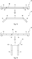
- FIG. 4 shows a completely straight rod 10 with two handles 12 and a treatment section 14 extending therebetween.
- the treatment portion 14 is located on an axis 36 except for a central portion 30.
- the handles 12 also lie on the axis 36.
- the central portion 30 is bent and is concave with respect to a body portion 28, in this case a thigh.
- FIG. 6 is the treatment section 14 except for a central portion 30 on two axes 36, which form an angle 38.
- the handles 12 are also on each of the axes 36.
- the central portion 30 is bent and is opposite to a body portion 28, in this case a back area, convex.
- FIG. 8 The symmetrically formed treatment section is bent in a central region and bent in its two end portions in opposite directions to the central portion 30.
- the handles 12 are clearly bent relative to the treatment portion 14.
- This treatment rod is suitable for the treatment of a rump or back region shown with a body portion 28.
- FIGS. 9 and 10 show further embodiments of a treatment rod 10 here with only a handle 12.
- the handle 10 opposite end face 39 is in the FIGS. 11 to 13 shown in various trainings that are not meant to be understood.
- the treatment bar flexes his the end face 39 having end portion 40 in Fig. 9 by an angle 42 of about 90 degrees.
- Fig. 10 the end portion is bent at an angle of 180 degrees. With such treatment bars, the treatment of the back can be done without the treatment rod would have to be positioned over the shoulder over it.
- the handle 12 subsequent treatment section have in FIGS. 9 and 10 shown treatment bars 2 not shown here parallel to the longitudinal axis of the treatment bar edges.
- Fig. 11 to 13 show views on end faces 39 of end sections, as shown in the FIGS. 9 and 10 were explained.
- Fig. 11 shows with the views A and B each have a side view and view C is a plan view of an end face 39, which is formed here projecting on an oval base.
- FIG. 12 shows a view from view A is a plan view and with view B a side view of the frusto-conical end of the end portion 40 of a treatment rod according to the FIGS. 9 and 10 ,
- FIG. 13 further shows a part-spherical end face 38 of the end portion 40 according to FIGS. 9 and 10 , where view A is a side view and view B is a plan view of the front page 39.
- a tissue treatment rod 10 is a pivotal function, with the parts of the treatment rod 10 can be rotated about a rotation axis 46 against each other to reach over two joints 44 different angles of attack of the treatment portion 14 against two handles 12 and thereby the treatment success for hard to reach places to allow about the back part.
- the treatment bar 10 can be compactly compacted by such, in particular in several angles lockable joints 44, such as for easier transportation or travel or for small-scale storage of the treatment rod, as in Fig. 15 shown below.
- the Fig. 16 shows a detail of a sectional view through a treatment rod, namely a coating with nano silver particles having plastic material 48 on a treatment section 14. As is known, thereby adhesion of pathogens, in particular at the treatment section 14, difficult or completely prevented.
- FIGS. 17 and 18 show various arrangement of vibrating elements in the form of two or three vibration motors 18 within a treatment rod.
- Fig. 17 is shown a symmetrical arrangement of the vibration motors 18 and in Fig. 18 a non-symmetrical arrangement of the vibration motors 18 is shown, in which there are three vibration motors on the right side of the tissue treatment rod 10 shown here.
- FIG. 12 shows an arrangement of a translucent portion within a treatment portion 14 of a treatment rod 10.
- the translucent portion is made of plastic material and extends only over a part of the treatment portion 14.
- a light source (not shown) transmits UV light through the translucent portion 50.
- FIGS. 20 and 21 shows in various views a further arrangement of a translucent portion 50 within a treatment portion 14 of a treatment rod 10.
- the translucent portion 50 is formed of glass material and extends almost completely along the treatment portion 14 and forms part of it.
- An edge 24 is formed by the glass material used.
- a light source 52 transmits IR light through the translucent portion 50.
- FIGS. 22 and 23 each show an arrangement of a heating element 54 in the form of a known heat conductor below an edge 24 within a treatment rod 10.
- the heating element is placed in a passage opening provided for this purpose and in Fig. 23 is an insulation 56 of the heating element directly on a protective layer 58 of paint and forms with this an edge 24th
- Fig. 24 shows a treatment bar 10 which is connected by means of a USB connector 60 to a hand-held device 62 in the form of a smartphone.
- the USB connector 60 allows not only the transmission of data nor the charging of an existing in the treatment bar 10 accumulator not shown here.
- a treatment bar 10 communicates via a hand-held device 62 with an internet cloud 164.
- a communication interface 166 is provided in the form of a WLAN connection.
- the Fig. 26 shows a further treatment rod 10 with an edge 24 which is completely rounded off on both sides.
- the edge 24 itself has a radius of 7 mm in the center of the rod (section C-C ') and in an end region (section B-B', section D).
- D ' a smaller radius of about 2mm or at the end (section A-A') no edge radius, which is different from the radius of the treatment rod.
- the radius reduction is linear from both sides of the center (section C-C ').
- the Fig. 27 shows a further treatment rod 10 with a partially oval cross-section with an edge 24 completely rounded on both sides.
- the edge 24 itself has a radius of 25 mm in the center of the rod (section C-C ') and thus merges into the basic shape of the rod cross-section. In one end region (section B-B '), the edge has a smaller radius of about 3 mm. The radius reduction is linear from both sides of the center (section C-C ').
- Fig. 28 shows various edge shapes in a respective sectional view, in which the edge 24 of the view A is a projection, in the views B, C and D, the edge 24 has a radius of 8, 4 and 2mm.
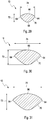
- Fig. 29 to 31 show different cross-sections through a treatment rod 10th
- FIG. 29 For example, various radii in a section of a fabric treatment rod are shown in a cross-sectional view, namely, two edge radii 64 of 2 mm, a radius 66 of 20 mm, a radius 68 of 9.5 mm, and a radius 70 of 100 mm.
- the treatment rod has a height 72 of 18.2 m and a width 74 of 28.8 mm.
- FIG. 30 For example, various radii are shown in a section of an alternative fabric treatment bar 10 having a vibratory motor 18 disposed therein in a sectional view, namely, edge radii 64 of 2 mm, radius 66 of 35 mm, and radius 70 of 177 mm.
- the treatment rod has a height 72 of 32 mm and a width 74 of 52 mm.
- FIG. 31 For example, various radii are shown in a section of another tissue treatment bar 10 with a vibratory motor 18 disposed therein in a sectional view, namely 4 mm edge radii 64, 39 mm radius 66, and 194 mm radius 70.
- the treatment rod has a height 72 of 35 mm and a width 74 of 57 mm.
- an edge or an edge-forming radius has a cross-sectional radius which is smaller by at least a factor 3, preferably at least a factor 5, more preferably at least a factor 10, even more preferably at least a factor 15, than any radius of two immediately adjacent to the edge-forming radius or the edge adjacent sections.
- radius 64 is by definition still to be considered as 6.6 mm as the edge-forming radius or edge 24, since the section with the smallest radius adjacent to it is 20 mm.
- the definition can still be restricted as follows: The smallest radius of a section adjacent to the edge-forming radius is always greater than 15 mm.
- Fig. 32 an exploded view of a treatment bar 10 with two handles 12 in the form of covers and a treatment section 14.
- a steel tube 76 is inserted into an opening 78 of the treatment section 14.
- the gripping pieces 80, a securing element 82, an eccentric element 84 for generating the vibration movement, a vibration motor 18, a motor bracket 86 are inserted.
- a battery holder 88 is further shown with a plug contact 90, which can be inserted or pushed through the handle 80 shown on the right.
- a cover 92 is still shown with holder 94, wherein an actuating element 96 is disposed in one of the covers 92. By means of the actuating element 96, the motor 18 of the treatment rod can be switched on and off.
- a power supply 98 and a USB connector 60 for power supply or for charging an accumulator of the treatment rod 10 is shown.
- Fig. 33 a perspective view of a treatment rod according to Fig. 33 , wherein still a USB socket 102 is shown, with which the power supply 98 or other devices can be connected.
- Fig. 34 a sectional view of a treatment rod according to Fig. 33 and the Fig. 35 shows a sectional view of an alternative treatment rod 10 which tapers from outside to inside.
Landscapes
- Health & Medical Sciences (AREA)
- Epidemiology (AREA)
- Pain & Pain Management (AREA)
- Physical Education & Sports Medicine (AREA)
- Rehabilitation Therapy (AREA)
- Life Sciences & Earth Sciences (AREA)
- Animal Behavior & Ethology (AREA)
- General Health & Medical Sciences (AREA)
- Public Health (AREA)
- Veterinary Medicine (AREA)
- Percussion Or Vibration Massage (AREA)
Description
- Zum Lösen von muskulären Verspannungen sind Massagestäbe mit zwei Handgriffen und einem zwischen den Handgriffen angeordneten Behandlungsabschnitt bereits seit Jahrzehnten bekannt. Bei diesen Massagestäben weist der Behandlungsabschnitt mehrere nebeneinander angeordnete Rollen auf, die drehbar auf einer Achse gelagert sind. An den Enden dieser Achse sind die Handgriffe angeordnet. Dieser Massagestab wird mit beiden Händen gegriffen und dann werden die Rollen des Behandlungsabschnitts über die zu behandelnden Muskelpartien gerollt und erzeugen dadurch eine gewisse Massagewirkung.
- Insbesondere sind Massagegeräte aus der
US 2, 307,554 A , derEP 0 116 113 A2 , derUS 2003/0105417 A1 , derDE 20 2014 004 900 U1 , derUS 2013/012848 A1 , derEP 1 925 276 A1 , derUS 1 958 936 A , derWO 2011/034122A1 , derWO 2012/117923 A1 , derUS 5 123 406 A oder derDE 1904135 U bekannt. DieWO 2012/003652 A1 zeigt ein Gesichtmassagegerät mit ineinandergesteckten Massageblöcken, die drehbar auf einer Stange gelagert sind. - Der Erfindung liegt die Aufgabe zugrunde, einen Gewebe-Behandlungsstab mit gegenüber einem herkömmlichen Massagestab verbesserter Wirksamkeit bereitzustellen.
- Diese Aufgabe wird erfindungsgemäß gelöst durch einen Gewebe-Behandlungsstab, geeignet für die Behandlung von Bindegewebe, Muskeln, Muskel-Faszien oder Sehnen, umfassend einen Behandlungsabschnitt, dadurch gekennzeichnet, dass in dem Behandlungsabschnitt Mittel zum Erzeugen von Vibrationen vorgesehen sind, dass die Mittel zum Erzeugen von Vibrationen den Behandlungsabschnitt in Vibration versetzen, und dass der Behandlungsabschnitt zwei oder drei Kanten aufweist, wobei die Kanten parallel zu einer Längsachse des Gewebe-Behandlungsstabs verlaufen, wobei die Mittel zum Erzeugen von Vibrationen eine gerichtete oszillierende Bewegung des Behandlungsabschnitts erzeugen, wobei die Richtung der oszillierenden Bewegung radial von einem Mittelpunkt des Behandlungsabschnitts durch zumindest eine der Kanten verläuft, wobei zumindest eine der Kanten einen kantenbildenden Querschnitts-Radius aufweist, der um mindestens einen Faktor 3, bevorzugt mindestens einen Faktor 5, noch bevorzugt mindestens einen Faktor 10, noch bevorzugt mindestens einen Faktor 15 kleiner ist, als jeder Radius zweier unmittelbar zu dem kantenbildenden Querschnitts-Radius benachbarte Abschnitte.
- Dann nämlich wirken die oszillierenden Bewegungen bei der Anwendung des Gewebe-Behandlungsstabs senkrecht in das zu behandelnde Gewebe hinein und entfalten auf diese Weise mit minimalstem Energieeintrag eine maximale therapeutische Wirkung.
- Dadurch, dass der Behandlungsabschnitt mindestens eine ausgeprägte Kante aufweist ist es möglich, kurzzeitig einen höheren lokalen Druck zu erzeugen, als wenn eine Rolle über den zu behandelnden Bereich bzw. die zu behandelnde Muskelpartie rollt. Schon dadurch wird eine intensivere Wirkung und tiefer in das Gewebe hineinreichende Wirkung als bei eine Massage erzielt. Es hat sich bei Studien herausgestellt, dass der Tonus des Gewebes schon nach einer sehr kurzen Behandlungszeit von wenigen Minuten signifikant reduziert wurde.
- Weiter verstärkt wird diese Wirkung durch die Schwingungen in die der Behandlungsabschnitt versetzt wird. Dadurch werden auch tiefe und nicht direkt zugängliche Bereiche des Bindegewebes bzw. der Muskeln, der Muskel-Fascien oder Sehnen behandelt und infolgedessen werden auch diese Bereiche entspannt und evtl. vorhandene Verklebungen oder Verfilzungen der Fascien, Verkrampfungen oder sogenannte Triggerpunkte gelöst. Im Folgenden wird aus Gründen der sprachlichen Vereinfachung häufig der Begriff "Gewebe" verwandt. Dieser Begriff umfasst Bindegewebe, Muskeln, Muskel-Fascien und/oder Sehnen.
- Es hat sich als vorteilhaft erwiesen, dass die Mittel zum Erzeugen von Vibrationen den Behandlungsabschnitt in Vibrationen mit einer Frequenz von weniger als 100 Hz, bevorzugt von weniger als 60 Hz, und besonders bevorzugt von weniger als 40 Hz, versetzen.
- Bei Messungen der Wirksamkeit des erfindungsgemäßen Behandlungsabschnitts hat sich eine besonders intensive und entspannende Wirkung des Gewebe-Behandlungsstabs bei diesen relativ niedrigen Frequenzen ergeben.
- Außerdem dringen die niederfrequenten Vibrationen tiefer in das Bindegewebe und das Muskelgewebe ein, so dass auch aus diesem Grund eine niederfrequente Anregung des Behandlungsabschnitts wünschenswert ist.
- Es ist prinzipiell möglich, auf verschiedene Arten und Weisen die gewünschten Vibrationen zu erzeugen. Eine bewährte und für therapeutische Zwecke geeignete Möglichkeit besteht darin, einen elektrisch angetriebenen Vibrationsmotor, der mit einer Unwucht ausgestattet ist, zu verwenden. Solche elektrisch angetriebenen Vibrationsmotoren sind am Markt in verschiedensten Ausführungen verfügbar. Die gewünschte Frequenz wird über die Drehzahl des Vibrationsmotors und/oder ein Untersetzungsgetriebe eingestellt. Es ist selbstverständlich vorteilhafterweise auch möglich, die Drehzahl des Vibrationsmotors steuerbar zu machen, so dass der Therapeut je nach Anwendung die gewünschte Frequenz einstellen kann.
- Wenn der Behandlungsabschnitt mehr als eine Kante aufweist, dann ist in weiterer vorteilhafter Ausgestaltung der Erfindung vorgesehen, die Richtung der oszillierenden Bewegung wahlweise auf eine der verschiedenen Kanten richten zu können.
- Bei einem Behandlungsabschnitt mit zwei oder alternativ drei Kanten, sind diese in der Regel mit einem Winkel von 180° bzw. bei drei Kanten von 120° gleichmäßig über den Umfang verteilt.
- Wenn man nun bei einem Gewebebehandlungsstab mit drei Kanten die Möglichkeit vorsieht, den Behandlungsabschnitt relativ zu den Handgriffen jeweils um 120° zu verdrehen, dann kann man jede der Kanten so positionieren, dass die oszillierenden Vibrationen genau auf die gewünschte Kante gerichtet sind. Dabei wird vorausgesetzt, dass sich die Mittel zum Erzeugen der gerichteten oszillierenden Bewegung während des Einstellvorgangs nicht relativ zu den Handgriffen verdrehen.
- Dadurch wird der gewünschte Effekt, nämlich die Ausrichtung der gerichteten oszillierenden Bewegung auf genau eine Kante, auf einfache Weise erzielt. Selbstverständlich gilt dies analog für einen Gewebe-Behandlungsstab mit zwei, oder nicht erfindungsgemäß vier oder fünf Kanten. Selbstverständlich gibt es auch weitere Möglichkeiten der Ausrichtung.
- Eine gerichtete oszillierende Bewegung kann beispielsweise dadurch erzielt werden, dass zwei gegenläufig rotierende Unwuchten vorgesehen sind. In einer ersten Raumesrichtung addieren sich die Unwuchten und in einer zweiten orthogonal zur ersten Raumesrichtung heben sich die Unwuchten gegenseitig auf. Es sind auch andere Möglichkeiten bekannt, aus einer umlaufenden Unwucht eine gerichtete oszillierende Bewegung herzustellen.
- Es hat sich als vorteilhaft erwiesen, wenn mindestens eine Kante aus Holz besteht. Holz wird von der Haut eines Patienten als sehr angenehm wahrgenommen. Außerdem ist es ein sehr leichter und belastbarer Werkstoff, der auch dauernden Vibrationen ausgesetzt werden kann, ohne dass es zu einer Materialermüdung kommt.
- Es hat sich weiter als vorteilhaft erwiesen, eine Kante aus einem gummielastischen Material herzustellen. Dadurch ist eine sehr weiche und schonende Behandlung des Gewebes möglich. Diese Kante wird vor allem im Bereich von Sehnen, wie z. B. der Achillessehne, oder im Bereich des Kniegelenks eingesetzt, wo eine vergleichsweise harte Kante aus Holz vom Patienten als schmerzhaft empfunden werden würde.
- Es ist außerdem möglich, dass die mindestens eine Kante Rippen aufweist, um eine noch weichere Kante auszubilden.
- Wenn beispielsweise an einem erfindungsgemäßen Gewebe-Behandlungsstab drei Kanten mit jeweils unterschiedlichen Härten bzw. Eigenschaften angeordnet sind, dann hat der Therapeut oder der Selbstanwender immer eine geeignete für die jeweils zu behandelnde Partie des Körpers geeignete Kante zur Verfügung.
- Es ist auch vorteilhaft, wenn mindestens eine der Kanten auswechselbar ist. Dann kann z. B. eine verschlissene Kante einfach ausgewechselt werden oder es können den Bedürfnissen verschiedener Patienten entsprechend jeweils die am besten geeigneten Kante in den Gewebe-Behandlungsstab eingesetzt werden.
- Eine weitere vorteilhafte Ausgestaltung des erfindungsgemäßen Gewebe-Behandlungsstabs sieht vor, dass mindestens in einem der Handgriffe eine Aufnahme für Batterien oder Akkumulatoren vorgesehen ist. Dann kann auf einfache Weise die Energieversorgung des elektrischen Vibrationsmotors gewährleistet sein. Außerdem führt die relativ große Masse der Akkumulatoren dazu, dass die Handgriffe eine große Massenträgheit haben. Deshalb werden die Vibrationen des Behandlungsabschnitts nur zu einem sehr geringen Teil auf die Handgriffe übertragen. Dadurch ist es möglich, dass ein Therapeut auch über viele Stunden am Tag mit dem erfindungsgemäßen Gewebe-Behandlungsstab arbeiten kann, ohne zu ermüden und ohne das Durchblutungsstörungen, die durch die Vibrationen ausgelöst werden können, zu befürchten sind.
- Um zu gewährleisten, dass keine zu großen Kräfte mit der Kante auf das zu behandelnde Gewebe ausgeübt werden, ist mindestens ein Kraftsensor, bevorzugt aber zwei oder mehr Kraftsensoren vorgesehen, welche die zwischen den Handgriffen und dem Behandlungsabschnitt wirkenden Kräfte erfassen. Wenn die Kräfte einen vorgegebenen Grenzwert übersteigen, dann wird beispielsweise ein Signal (optisch und/oder akustisch) aktiviert. Alternativ oder ergänzend ist es auch möglich, dass in diesem Fall der Vibrationsmotor abgeschaltet wird.
- Dadurch werden Fehlbehandlungen wirkungsvoll vermieden und es können auch medizinische Laien sich gefahrlos mit dem erfindungsgemäßen Gewebe-Behandlungsstab selbst behandeln.
- Während der von dem in Normalrichtung zur Längsrichtung des Gewebe-Behandlungsstabs liegende Querschnittsradius vermittelte Kreis den Querschnitt des Gewebe-Behandlungsstabs überdeckt, also mit anderen Worten innen liegt, muss dies nicht zwangsläufig auch für die von den Radien der unmittelbar an den kantenbildenden Radius angrenzenden Abschnitte gebildeten Kreise gelten. Letztere können in einer weiteren Ausführung in der Tat den Querschnitt des Gewebe-Behandlungsstabs nicht überdecken, mit anderen Worten außen von diesem liegen. Bevorzugt ist jedoch die Querschnittskontur des Behandlungsstabes mit ausschließlich den Querschnitt überdeckenden bzw. teilweise überdeckenden Kreisen vorzusehen. Es versteht sich im Übrigen, dass der Übergang von einer durch einen Radius gebildeten Kontur zu einer von einem davon verschiedenen Radius gebildeten Kontur nicht streng geometrisch zu verstehen ist, sondern dass auch ein weicher Übergang an dieser Stelle noch im Rahmen der oben genannten Definition der Kante zu verstehen ist.
- In weiteren vorteilhaften Ausführungsformen ist vorgesehen, den Gewebebehandlungsstab und insbesondere den Behandlungsabschnitt der zu behandelnden Körperform anzupassen. Die Anpassung an die zu behandelnde Körperform kann sich dabei etwa auf Körperregionen wie den Nacken- oder den Schulterbereich des Anwenders oder des Patienten beziehen. Die Anpassung des Behandlungsabschnitts kann dabei vollständig oder teilweise vorgesehen sein.
- Ein Vorteil dieser Anpassung ist, dass Körperregionen bei gleicher Behandlungsdauer mit einer größeren Fläche behandelt werden können, als bei Verwendung eines gerade ausgebildeten Behandlungsabschnitts. So ist im Rücken- oder Steißbereich ein zur Körperoberfläche konvexer, d.h. nach außen gewölbter Abschnitt innerhalb des Behandlungsabschnitts vorteilhaft. Diese konvexe Form kann in einem Ausführungsbeispiel zentral angeordnet sein, wobei in einer Fortbildung zwei sich zu beiden Enden des konvexen Abschnitts anschließende Abschnitte wiederum gerade ausgebildet sein können. In einer anderen Ausführung können die sich zu beiden Enden des konvexen Abschnitts anschließende Abschnitte in Bezug auf die zu behandelnde Körperregion konkav, d.h. nach innen gewölbt ausgebildet sein, um etwa Körperregionen die sich quer zur lateral verlaufenden Rückgratregion an diese anschließen, schneller und gründlicher behandeln zu können.
- Ferner können die genannten Abschnitte für sich allein oder, falls ein oder zwei Handgriffe vorgesehen sind, diese auf einer Achse liegen oder -in einem anderen Ausführungsbeispiel- einen Winkel bilden, dessen Scheitelpunkt allerdings auch außerhalb des Behandlungstabes liegen kann.
- Die oben genannte Anpassung kann beispielsweise noch dadurch verwirklicht sein, dass ein insbesondere mittiger Abschnitt des Behandlungsabschnitts oder der gesamte Behandlungsabschnitt gebogen, insbesondere kreisringförmig gebogen, ist.
- In einer Ausführungsform liegen dabei zumindest die beiden Handgriffe auf einer gemeinsamen Mittelachse und der dazwischenliegende Behandlungsabschnitt ist in seinem Längsverlauf beispielsweise kreisringförmig oder ähnlich einer Sinus-Halbwellenfunktion gebogen ausgeführt. Die Übergänge der um die eine Mittelachse liegenden Abschnitten, insbesondere der Handgriffe zu dem im Längsverlauf gebogenen Behandlungsabschnitt können fließend ausgebildet sein. Ein unmittelbarer stufiger Übergang zwischen diesen Abschnitten ist als alternative Ausführung ebenfalls vorgesehen.
- In einer weiteren Ausführung kann ferner der gesamte Stab, d.h. mitsamt der beiden äußeren Handgriffe, gebogen ausgeführt sein. Die Biegung kann dabei durch aufeinanderfolgende Abschnitte verschiedener Radien ausgeführt sein. Alternativ kann die Biegung mittels eines einzigen Biegeradius ausgeführt sein.
- In einer weiteren Ausführung kann der Behandlungsstab auch in verschiedene Richtungen gebogen sein. So ist beispielsweise in einer Ausgestaltung der Erfindung vorgesehen, dass die beiden Handgriffe von einer gedachten Mittelachse des Behandlungsstabens zum Benutzer hin gebogen sind und ein Mittelabschnitt des Behandlungsabschnitts oder der gesamte Behandlungsabschnitt des Behandlungsstabes vom Benutzer weg gebogen ist.
- In allen Ausführungsbeispielen ist der Behandlungsstab bevorzugt seitensymmetrisch ausgebildet, d.h. die linke Seite und die rechte Seite des Behandlungsstabes sind in ihrer äußeren Form im Wesentlichen oder tatsächlich identisch.
- In einer Ausführungsform kann ferner vorgesehen sein, dass der Behandlungsstab einen, insbesondere einen einzigen, Handgriff ausweist und der Behandlungsabschnitt zusätzlich oder für sich allein an einem dem Handgriff gegenüberliegende Ende angeordnet ist.
- In dieser Ausführung ist vorgesehen, dass der Behandlungsstab an dem den Behandlungsabschnitt ausbildenden Ende gebogen ist. Die Biegung ist dabei bevorzugt spazierstockartig ausgebildet. Der durch die Biegung verursachte Bogen spannt einen Bogenwinkel von bevorzugt zwischen 80 und 320 Grad. Eine Kante des Behandlungsabschnitts ist ferner an der endseitigen Stirnfläche des Behandlungsabschnitts ausgebildet. Alternativ kann der Behandlungsabschnitt an dieser Stelle allerdings auch eine nicht kantenförmige Ausbildung aufweisen, etwa pyramidenförmig, Kegel- oder Kegelstumpfförmig oder teilkugelförmig ausgebildet sein.
- In einer weiteren Ausführungsform ist ferner vorgesehen, dass zumindest der Behandlungsabschnitt des Behandlungsstabes in seiner Form händisch veränderbar ist und insofern von dem Benutzer in die gewünschte Behandlungsform überführt werden kann.
- Ein Aspekt der genannten Ausführungsform kann eine Drehfunktion beinhalten, mit der Teile des Behandlungstabs gegeneinander verdreht werden können, um über ein Gelenk verschiedene Anstellwinkel des Behandlungsabschnitts gegenüber einem oder zwei Handgriffen zu erreichen und dadurch den Behandlungserfolg für schwer zu erreichende Stellen, etwa die Rückenpartie zu ermöglichen. Ferner kann der Behandlungsstab durch solche, insbesondere in mehreren Winkeln feststellbaren, Gelenke kompakt zusammengelegt werden, etwa für den erleichterten Transport oder die Reise bzw. zur kleinräumigen Aufbewahrung des Behandlungsstabs.
- In einer weiteren Ausführung wird vorgeschlagen, dass der Behandlungsabschnitt ein oder mehrere auswechselbare Teile aufweist. Diese auswechselbaren Teile sind beispielsweise mittels einfacher Rastelemente in den Grundkörper des Behandlungsstabes einrastbar. Zum einen gestattet die Auswechselbarkeit der Teile des Behandlungsabschnitts die leichte Reinigung, etwa das Entfernen von Ölen und dadurch eine verbesserte Hygiene. Zum anderen können Teile verschiedener Größe, insbesondere verschiedenen Durchmessers und/oder aus verschiedenem Material verwendet werden, wodurch eine Massagebehandlung durch die entsprechende Modifikation des Behandlungsstabes individualisierbar wird.
- Sofern die Handgriffe in einem weiteren Ausführungsbeispiel ebenfalls zu wechseln sind, etwa mittels einfacher Rast oder Schraubverbindungen, können verschiedene Größen der Handgriffe für verscheiden große Hände zur Nutzung eines Behandlungsstabs verwendet werden.
- Neben der Größe können die Handgriffe auch in Form und Material eine besondere Ausgestaltung aufweisen. So können die Handgriffe gemäß einem Ausführungsbeispiel gepolstert, insbesondere mittels eines Schaumstoffmaterials ausgeführt sein. Die Befestigung der Griffe an de, Behandlungsstab kann beispielsweise mittels Aufstecken, Einstecken, Verschrauben oder Verrasten erfolgen.
- In einer Ausführung ist vorgesehen, zwischen den Handgriffen und dem Behandlungsabschnitt eine Entkopplungseinrichtung vorzusehen, die die Vibrations- und/oder Schwingbewegung des Behandlungsabschnitts dämpft oder vollständig von den Handgriffen entkoppelt. Ein solches Entkopplungselement kann beispielsweise als Federelement, etwa als Torsionsfeder, vorgesehen sein.
- In einer weiteren Ausführungsform ist kann ferner vorgesehen sein, dass zumindest der Behandlungsabschnitt mit einer antibakteriellen und/oder antifungizider Beschichtung ausgerüstet ist. Eine solche Beschichtung kann beispielsweise Nanosilber aufweisen, dessen antibakterielle Wirkung hinlänglich bekannt ist.
- In einer weiteren Ausführung kann es ferner vorgesehen sein, dass die Vibration um weitere Bewegungsfunktionen ergänzt oder ersetzt ist. Beispielsweise könnte der Behandlungsabschnitt mit einer Klopffunktion ausgestattet sein. Die Ausführung einer Mechanik, die eine Klopffunktion solche Klopffunktion ausführen kann ist hinlänglich bekannt. Lediglich beispielhaft wird ein mittels eines Getriebes angetriebenes und dadurch spannbares Federelement genannt, das sich nach vorbestimmter Zeit bzw. einer voreinstellbaren Einstellkraft impulsartig entspannt und ein Hammerelement betätigt, dass auf ein Ambosselement schlägt bzw. klopft. Die Klopffrequenz kann fest eingestellt oder alternativ mittels einer Steuerung variiert werden. Bevorzugt ist dabei eine Klopffrequenz zwischen 0,5 und 10 Hz. Die Klopffrequenz kann moduliert vorgesehen sein und den Frequenzbereich einmal oder mehrfach überstreichen. Ferner kann auch die Klopfstärke, d.h. die Bewegungsamplitude in einer bevorzugten Ausführungsform des Behandlungsstabes moduliert sein. Es versteht sich, dass die genannten Elemente bevorzugt in einem Hohlraum des Behandlungsstabes angeordnet sind.
- Sofern der Behandlungsstab flexibel ist, kann in einem weiteren Ausführungsbeispiel noch eine Mechanik vorgesehen sein, die eine Knetfunktion des Behandlungsstabes, insbesondere für dessen Behandlungsabschnitt ermöglicht. Diese Knetfunktion kann in einem einfachen Fall etwa ein Hin- und Herbewegen oder teilweises oder vollständiges Rotieren eines Stababschnittes sein, dass mit einer gewissen Formänderung des jeweiligen Abschnitts, insbesondere des Behandlungsabschnitts einhergeht. Als einfaches Beispiel sei eine rotatorische Bewegung eines Pleuelelementes genannt, welches in einer flexiblen Hülle angeordnet ist. Innerhalb einer vollen Umdrehung eines Antriebs wird ein solches Pleuel im ausgefahrenen Zustand zu einer entsprechenden Ausbuchtung der Hülle führen womit eine einfache Knetfunktion erreichbar ist, die die Vibrationsmassage ergänzen bzw. ersetzen kann.
- In einer weiteren Ausführung ist ferner vorgesehen, dass der Schwingungserzeuger als Piezoelement ausgeführt ist. Neben Piezoaktuatoren eignen sich grundsätzlich auch weitere bekannte elektrische oder elektromechanische Schwingungserzeugungseinrichtungen. Lediglich beispielhaft und nicht einschränkend können vorspannbare Federelemente, thermisch betätigbare Schwingungserzeugungseinrichtungen, Verbrennungsmaschinen zur Schwingungserzeugung auf an sich bekannte Art verwendet werden.
- In einem Aspekt kann ferner vorgesehen sein, einen oder mehrere gleichartige oder voneinander verschiedene Schwingungserzeuger in dem Behandlungsstab zu positionieren. Außer einer zentralen Position kann der bzw. können die Schwingungserzeuger auch in Richtung in der linken und rechten Hälfte, des Stabes verteilt sein, dort entweder in einem äquidistanten Abstand zueinander oder auch mit unterschiedlichem Abstand.
- Es kann ferner als Fortbildung einer Ausführungsform vorgesehen sein, dass ein magnetisches Feld als permanentes Dauerfeld oder als Wechselfeld insbesondere in dem Bereich des Behandlungsabschnitts erzeugt wird, dass auf die zu behandelnde Körperregion einwirkt. Für ein magnetisches Dauerfeld kann in einem einfachen Fall ein Permanentmagnet verwendet werden, der in oder auf dem Behandlungsstab angebracht ist.
- Es kann ferner als Fortbildung einer Ausführungsform vorgesehen sein, dass eine lichtemittierende Einrichtung die Massagewirkung unterstützt.
So kann beispielsweise IR-Licht, rotes oder blaues oder grünes Licht mittels entsprechender LED oder anderer an sich bekannter Leuchtquellen verwendet werden. - Bevorzugt ist ein Teil des Behandlungsabschnitts als lichtdurchlässiger Abschnitt ausgebildet, der den Lichtdurchtritt ermöglicht. Der lichtdurchlässige Abschnitt kann beispielsweise als eine der vorgenannten Behandlungskanten ausgebildet sein, und sich somit über die Länge des gesamten Behandlungsabschnitts des Behandlungsstabes erstrecken. Ebenso ist es möglich den zwischen den Kanten liegenden Bereich des Behandlungsabschnitt mit einem lichtdurchlässigen Abschnitt zu versehen. Der lichtdurchlässige Abschnitt ist bevorzugt aus Glas oder Kunstglas gefertigt. Insbesondere für kleinere Abschnitte eignet sich ebenso Bergkristall oder ähnliche lichtdurchlässige Gesteine. Durch die Fortbildung des Behandlungsstabs mittels Lichtquellen kann beispielsweise Wärme die Massagewirkung unterstützen oder bei Verwendung von rotem, blauem, grünem oder weißem Licht ein positiver therapeutischer Einfluss insbesondere auf die behandelte Körperregion ausgeübt werden.
- In einer weiteren Ausführung ist ferner vorgesehen, dass der Behandlungsabschnitt durch zumindest ein Heizelement beheizt wird. Als Heizelement eignet sich ein Heizdraht oder eine Heizfolie. Die Heizelemente können -etwa mittels einer Lackschicht- abgedeckt und gegen äußere Einflüsse isoliert werden.
- Als besonders positiv zur Unterstützung einer Massagewirkung hat sich die akustische Unterstützung mittels eines in oder auf den Behandlungsstab integrierten Lautsprecher herausgestellt. Dieser Lautsprecher kann mit Audiowellen im Frequenzbereich von bevorzugt unter 100 Hz, besonders bevorzugt unter 60 Hz, noch bevorzugt unter 40 Hz betrieben werden.
- Auch unterhalb des hörbaren Frequenzbereichs, etwa von 16 Hz bis 21 Hz kann sich eine positive Unterstützung der Massagewirkung zeigen, weshalb auch dieser Frequenzbereich in einer weiteren Ausführung vorgesehen sein kann.
- In einem Aspekt kann daher ein Frequenzband verwendet werden, was in den nichthörbaren untern Frequenzbereich hineinragt, bzw. diesen Bereich überstreicht. In einem weiteren Aspekt ist die gewünschte Frequenz, insbesondere stufenlos einstellbar oder es können verschiedene Abspielprogramme aus einer gespeicherten Programmauswahl abgespielt werden. Es versteht sich, dass auch übliche Musik-/Hörspiel-/oder Meditationsstücke mittels des zumindest eines Lautsprechers abspielbar sind. Diese Audiostücke können in einem weiteren Aspekt über eine am Behandlungsstab vorgesehene USB-Buchse von anderen Geräten, etwa Smartphones, auf den Behandlungsstab übertragen werden.
- In einem weiteren Aspekt ist ferner vorgesehen, dass mittels einer in dem Behandlungsstab vorhandenen Buchse, Smartphones und andere Hand-hold-devices aufladbar sind.
- Über eine solche Buche sind ferner auch Massagemessdaten, die etwa von einer Speichereinrichtung des Behandlungsstabs gespeichert werden können abrufbar sind. Zu solchen Massagemessdaten gehören beispielsweise und nicht abschließend, die Behandlungsdauer, das gewählte Behandlungsprogramm, und sofern eine entsprechende Sensorik in dem Behandlungsstab vorhanden ist, die behandelten Körperregionen. Neben dem USB-Anschluss oder stattdessen können in dem Behandlungsstab auch weitere Einrichtungen zur Kommunikation mit anderen Geräten vorgesehen sein, etwa eine Infrarotschnittstelle, oder Vorrichtungen zur Ultraschall-, optischen oder Funk-Kommunikation. Die Kommunikation zwischen dem Behandlungsstab und einem weiteren Gerät, etwa einem Smartphone, kann beispielsweise von dem Benutzer erstellte Massageprogramme betreffen, die der Benutzer mit anderen Anwendern teilen möchte. Ferner sind Ausgaben von Anwendungen in verschiedenen Sprachen unter Nutzung der zur Verfügung gestellten Kommunikationskanäle möglich. Insbesondere kann ein Gerätepairing zwischen dem Behandlungsstab und einem weiteren Gerät vorgesehen sein, mittels dem eine Livekommunikation optional ermöglicht wird.
- In einem weiteren Aspekt kann in einem Ausführungsbeispiel eine Timerfunktion für den Behandlungsstab bereitgestellt werden, mittels der der Benutzer nach Überschreiten einer voreinstellbaren Behandlungszeit, etwa der Gesamtbehandlungszeit oder der empfohlenen Behandlungszeit bestimmter Körperpartien, den Behandlungsstab ausschaltet der ein akustisches oder ein optischen Warnsignal ausgibt.
- Es versteht sich, dass sich an den zumindest eine Kante aufweisenden Behandlungsabschnitt weitere Abschnitte anschießen können, die keine Kante aufweisen und die als drehbare Rolle, drehbarer Ball, drehbares Dreieck oder in anderen für die Massage geeigneten Formen ausgebildet sein können.
- Weitere Vorteile und vorteilhafte Ausgestaltungen der Erfindung sind der nachfolgenden Zeichnung, deren Beschreibung und den Patentansprüchen entnehmbar.
- Es zeigt teilweise schematisch
- Fig. 1
- eine Seitenansicht eines erfindungsgemäßen Gewebe-Behandlungsstabs;
- Fig. 2, 3
- verschiedene Ausführungsformen des erfindungsgemäßen Gewebe-Behandlungsstabs;
- Fig. 4 bis 8
- verschiedene weitere alternative Ausführungsformen eines erfindungsgemäßen Gewebe-Behandlungsstabs mit je einem Schnitt durch einen zu behandelnden Körperabschnitt eines Anwenders;
- Fig. 9, 10
- weitere Ausführungsformen eines Behandlungsstabs mit einem Handgriff;
- Fig. 11 bis 13
- Ansichten auf stirnseitige Behandlungsabschnitte eines Behandlungsstabs gemäß der
Fig. 9 und 10 ; - Fig. 14, 15
- Behandlungsstäbe mit relativ zueinander in ihrer Position veränderbaren Abschnitten;
- Fig. 16
- ein Detail einer Schnittansicht durch einen Behandlungsstab;
- Fig. 17, 18
- verschiedene Anordnung von Vibrationselementen innerhalb eines Behandlungsstabes;
- Fig. 19 bis 21
- je eine Anordnung eines lichtdurchlässigen Abschnitts innerhalb eines Behandlungsabschnitts eines Behandlungsstabes;
- Fig. 22, 23 je
- eine Anordnung eines Heizelements innerhalb eines Behandlungsstabes;
- Fig. 24
- einen Behandlungsstab angeschlossen an ein Hand-Hold-Device;
- Fig. 25
- einen Behandlungsstab mit einer drahtlosen Kommunikationsschnittstelle;
- Fig. 26
- einen weiteren Behandlungsstab mit einer zu beiden Seiten vollständig verrundeten Kante;
- Fig. 27
- einen weiteren Behandlungsstab mit einer zu beiden Seiten verrundeten Kante;
- Fig. 28
- verschiedene Kantenformen in jeweils einer Schnittansicht;
- Fig. 29 bis 31
- verschiedene Querschnitte durch jeweils einen Behandlungsstab;
- Fig. 32
- eine Explosionsansicht eines Behandlungsstabes;
- Fig. 33
- eine perspektivische Ansicht auf einen Behandlungsstab;
- Fig. 34
- eine Schnittansicht eines Behandlungsstabes gemäß
Fig. 33 und - Fig. 35
- eine Schnittansicht eines alternativen Behandlungsstabes.
- Die
Figur 1 zeigt eine schematische Darstellung eines erfindungsgemäßen Gewebe-Behandlungsstabs 10. An seinen Enden weist der Gewebe-Behandlungsstab zwei Handgriffe 12 auf. Zwischen den Handgriffen 12 ist ein Behandlungsabschnitt 14 ausgebildet. Wie durch einen Pfeil 16 angedeutet ist es möglich, den Behandlungsabschnitt 14 in eine oszillierende oder umlaufende Vibration zu versetzten. Erzeugt wird diese Vibration von Mitteln zum Erzeugen von Vibrationen 18, die in aller Regel als Elektromotor mit einer Unwucht ausgebildet sind. Um die Energieversorgung dieses Elektromotors zu gewährleisten, sind in den Handgriffen 12 Aufnahmefächer 20 für Akkumulatoren oder Batterien ausgebildet. - Die Aufnahmefächer 20 können mithilfe eines einfachen, bevorzugt werkzeuglosen, montierbaren und demontierbaren Deckels 22 geöffnet und verschlossen werden. Dadurch ist es möglich, ähnlich wie bei einer Stabtaschenlampe, die Akkumulatoren in kürzester Zeit auszuwechseln und in eine Ladestation (nicht dargestellt) zu geben. Während des Ladevorgangs kann ein zweiter Satz Akkumulatoren in den Gewebe-Behandlungsstab 10 eingesetzt werden, so dass dieser zeitlich nahezu unbegrenzt lang betrieben werden kann.
- Es ist selbstverständlich auch möglich, dass die Akkumulatoren in den Aufnahmefächern 20 durch ein externes Ladekabel geladen werden. Die dazu erforderliche Buchse ist in der
Figur 1 nicht dargestellt. - Die elektrischen Leitungen von diesen Aufnahmefächern 20 zu den Mitteln zum Erzeugen von Vibrationen 18 sind in der schematischen Darstellung der
Figur 1 nicht dargestellt. Des Weiteren sind ein Ein-/Ausschalter, Anzeigen, wie z. B. ein visuelles Warnsignal (LED oder Display), das ausgegeben wird, wenn die auf das Gewebe ausgeübte Kraft zu groß ist, in derFigur 1 nicht dargestellt. - In der
Figur 1 sind Kraftmesseinrichtungen 32 schematisch dargestellt, welche die zwischen Handgriffen 12 und Behandlungsabschnitt 14 wirkenden Kräfte erfassen. Wenn ein zulässiger Grenzwert überschritten wird, dann wird ein akustisches und/oder optisches Signal erzeugt. Alternativ ist es auch möglich, den Vibrationsmotor 18 in diesem Fall abzuschalten. Damit werden unzulässig hohe Kräfte wirkungsvoll verhindert und es vermieden, dass der Patient am Tag nach der Behandlung blaue Flecken oder andere Beschwerden hat. - In der
Figur 2 ist ein Querschnitt entlang der Linie A-A gemäßFigur 1 dargestellt. Bei diesem Ausführungsbeispiel hat der Behandlungsabschnitt 14 zwei einander gegenüberliegende Kanten 24 und 26, die in der Schnittdarstellung derFigur 2 durch einen Kreisbogen miteinander verbunden sind. Die Kanten 24 und 26 sind etwas verrundet und keinesfalls scharfkantig, da mit den Kanten 24 und 26 der Behandlungsabschnitt 14 über das zu behandelnde Gewebe gestrichen wird. Eine Behandlung mit einer zu scharfen Kante würde vom Patienten als schmerzhaft wahrgenommen werden und könnte sogar zu Verletzungen führen. Ein Radius von 2 mm bis 8 mm als minimaler Krümmungsradius an den Kanten 24 und 26 hat sich als vorteilhaft erwiesen. Die Kanten verlaufen bevorzugt in etwa oder vollkommen parallel zu einer Längsachse 11 des Gewebe-Behandlungsstabs. Zumindest im Bereich der Kante 24 ist der Behandlungsabschnitt 14 bevorzugt aus Holz ausgebildet, unter anderem weil Holz vom Patienten als angenehm wahrgenommen wird. Außerdem ist Holz ein leichter und sehr leistungsfähiger Werkstoff, der auch bei langem Gebrauch keine Ermüdungserscheinungen zeigt, auch wenn er über viele hundert Stunden mit Vibrationen beaufschlagt wird. - Die Kante 26 kann in dem Behandlungsabschnitt 14 eingesetzt und besteht in einer weiteren Ausführung bevorzugt aus einem gummielastischen Material. Dieses gummielastische Material ist sehr viel weicher als das Holz an der Kante 24. Daher eignet sich die Kante 26 besonders zur Behandlung von Partien, die wenig Bindegewebe oder Muskelmasse aufweisen. Beispielsweise kann mithilfe der Kante 26 die Achillessehne oder Partien im Bereich des Knies gut behandelt werden.
- In der
Figur 2 sind die Mittel zur Erzeugung von Vibrationen 18 dargestellt. Der gekrümmte Pfeil (ohne Bezugszeichen) soll die umlaufende Unwucht eines Vibrationsmotors andeuten. - In der
Figur 3 ist ein weiteres Ausführungsbeispiel eines erfindungsgemäßen Behandlungsabschnitts 14 dargestellt. Bei diesem Ausführungsbeispiel ist der Behandlungsabschnitt 14 in der Art einer Trochoide und weist drei Kanten 24, 26 und 28 auf. Die Kanten 24 und 26 können genauso ausgebildet sein, wie die anhand derFigur 2 erläuterten. - Die dritte Kante 28 kann beispielsweise auch als auswechselbare Kante aus einem gummielastischen Material ausgebildet sein und zusätzlich mehrere Rippen 30 aufweisen, die die Kante 28 noch weicher und flexibler werden lassen.
- In den
Figuren 2 und 3 ist durch Pfeile 34 eine Ausführungsform angedeutet, bei der der Behandlungsabschnitt 14 in eine oszillierende Bewegung gebracht wird, wobei diese oszillierende Bewegung eine Richtung hat, die ausgehend von einem Mittelpunkt M des Behandlungsabschnitts 14 radial nach außen zu einer oder im Falle derFigur 2 zu beiden Kanten 24 bzw. 26 gerichtet ist. - Wenn dem Behandlungsabschnitt 14 eine oszillierende Bewegung aufgeprägt wird, dann wird mit minimalem Energieeinsatz eine maximale Tiefenwirkung der Behandlung erreicht. Besonders vorteilhaft ist es in diesem Fall, wenn zwei Kanten 24, 26 einander gegenüberliegend angeordnet sind, weil dann durch einfaches Drehen eine Umsetzung des erfindungsgemäßen Gewebe-Behandlungsstabs 10 um 180° die gewünschte Kante 24 oder 26 zum Einsatz kommen kann. Dabei ist es nicht erforderlich, die Richtung der oszillierenden Bewegung zu ändern.
- Anders verhält es sich bei dem Ausführungsbeispiel gemäß
Figur 3 . Wenn bei diesem Ausführungsbeispiel eine gerichtete oszillierende Bewegung 34 dem Behandlungsabschnitt 14 aufgeprägt wird, dann ist es empfehlenswert, wenn diese Richtung ausgehend vom Mittelpunkt M radial nach außen wahlweise auf eine der Kanten 24, 26 oder 28 gerichtet werden kann. Dies kann einfacherweise dadurch erreicht werden, dass der Behandlungsabschnitt 14 relativ zu den Handgriffen und den Mitteln zum Erzeugen einer gerichteten Unwucht 18 um jeweils 120° verdreht wird, wenn eine andere Kante zum Einsatz kommen soll. - In
Fig. 4 bis 8 sind verschiedene weitere alternative Ausführungsformen eines erfindungsgemäßen Gewebe-Behandlungsstabs 10 mit je einer Schnittansicht durch einen zu behandelnden Körperabschnitt 28 eines Anwenders gezeigt. -
Figur 4 zeigt dabei einen vollständig geraden Stab 10 mit zwei Handgriffen 12 und einem dazwischen verlaufenden Behandlungsabschnitt 14. - In
Figur 5 liegt der Behandlungsabschnitt 14 bis auf einen zentralen Abschnitt 30 auf einer Achse 36. Die Handgriffe 12 liegen ebenfalls auf der Achse 36. Der zentrale Abschnitt 30 ist gebogen und ist gegenüber einem Körperabschnitt 28, in diesem Fall einem Oberschenkel, konkav ausgebildet. - In
Figur 6 liegt der Behandlungsabschnitt 14 bis auf einen zentralen Abschnitt 30 auf zwei Achsen 36, die einen Winkel 38 aufspannen. Die Handgriffe 12 liegen ebenfalls auf jeweils einer der Achsen 36. Der zentrale Abschnitt 30 ist gebogen und ist gegenüber einem Körperabschnitt 28, in diesem Fall einem Rückenbereich, konvex ausgeführt. - In
Figur 7 ist liegt der vollständig gebogene Behandlungsabschnitt 14 nicht mehr auf der Achse 36 sondern wölbt gegenüber einem Körperabschnitt 28. - In
Figur 8 verläuft der symmetrisch ausgebildete Behandlungsabschnitt in einem zentralen Bereich gebogen und in seinen beiden Endabschnitten gegenläufig zum zentralen Abschnitt 30 gebogen. Die Handgriffe 12 sind deutlich abgeknickt gegenüber dem Behandlungsabschnitt 14. Dieser Behandlungsstab ist geeignet für die Behandlung eines mit einem Körperabschnitt 28 gezeigten Steiß- oder Rückenbereiches. - Die
Figuren 9 und 10 zeigen weitere Ausführungsformen eines Behandlungsstabs 10 hier mit lediglich einem Handgriff 12. Die dem Handgriff 10 gegenüberliegende Stirnseite 39 ist in denFiguren 11 bis 13 in verschiedenen Ausbildungen gezeigt, die nicht abschließend aufgefasst werden sollen. Der Behandlungsstab biegt sich mit seinem die Stirnseite 39 aufweisenden Endabschnitt 40 inFig. 9 um einen Winkel 42 von etwa 90 Grad. InFig. 10 ist der Endabschnitt in einem Winkel von 180 Grad gebogen. Mit derartigen Behandlungsstäben kann die Behandlung des Rückens erfolgen, ohne dass der Behandlungsstab dafür über die Schulter hinüber positioniert werden müsste. Im geraden, sich dem Handgriff 12 anschließenden Behandlungsabschnitt besitzen die inFig. 9 und Fig. 10 gezeigten Behandlungsstäbe 2 hier nicht gezeigte zur Längsachse des Behandlungsstabes parallel verlaufende Kanten. - Die
Fig. 11 bis 13 zeigen Ansichten auf Stirnseiten 39 von Endabschnitten, wie sie in denFiguren 9 und 10 erläutert wurden.Fig. 11 zeigt mit den Ansichten A und B je eine Seitenansicht und Ansicht C eine Draufsicht auf eine Stirnseite 39, die hier auf einer ovalen Grundfläche vorspringend ausgebildet ist. -
Figur 12 zeigt mit Ansicht A eine Aufsicht und mit Ansicht B eine Seitenansicht auf das kegelstumpfförmige Ende des Endabschnitts 40 eines Behandlungsstabs gemäß derFig. 9 und 10 . -
Figur 13 zeigt ferner eine teilkugelförmige Stirnseite 38 des Endabschnitts 40 gemäß derFiguren 9 und 10 , wobei Ansicht A eine Seitenansicht und Ansicht B eine Aufsicht auf die Stirnseite 39 zeigen. - Bei den in
Fig. 14 und Fig. 15 gezeigten Ausführungen eines GewebeBehandlungsstabes 10 ist eine Drehfunktion vorhanden, mit der Teile des Behandlungstabs 10 gegeneinander um eine Drehachse 46 verdreht werden können, um über zwei Gelenke 44 verschiedene Anstellwinkel des Behandlungsabschnitts 14 gegenüber zwei Handgriffen 12 zu erreichen und dadurch den Behandlungserfolg für schwer zu erreichende Stellen, etwa die Rückenpartie zu ermöglichen. Ferner kann der Behandlungsstab 10 durch solche, insbesondere in mehreren Winkeln feststellbaren, Gelenke 44 kompakt zusammengelegt werden, etwa für den erleichterten Transport oder die Reise bzw. zur kleinräumigen Aufbewahrung des Behandlungsstabs, wie inFig. 15 unten gezeigt ist. - Die
Fig. 16 zeigt ein Detail einer Schnittansicht durch einen Behandlungsstab, nämlich eine Beschichtung mit Nanosilber-Partikel aufweisendem Kunststoffmaterial 48 auf einem Behandlungsabschnitt 14. Bekanntermaßen kann dadurch ein Anhaften von Krankheitserregern, insbesondere an dem Behandlungsabschnitt 14, erschwert oder gänzlich verhindert werden. - Die
Fig. 17 und 18 zeigen verschiedene Anordnung von Vibrationselementen in Form von zwei bzw. drei Vibrationsmotoren 18 innerhalb eines Behandlungsstabes. InFig. 17 ist eine symmetrische Anordnung der Vibrationsmotoren 18 gezeigt und inFig. 18 ist eine nicht-symmetrische Anordnung der Vibrationsmotoren 18 gezeigt, bei sich drei Vibrationsmotoren auf der hier rechts dargestellten Seite des Gewebe-Behandlungsstabs 10 befinden. -
Fig. 19 zeigt eine Anordnung eines lichtdurchlässigen Abschnitts innerhalb eines Behandlungsabschnitts 14 eines Behandlungsstabes 10. Der lichtdurchlässige Abschnitt ist aus Kunststoffmaterial und erstreckt sich nur über einen Teil des Behandlungsabschnitts 14. Eine hier nichtgezeigte Lichtquelle sendet UV-Licht durch den lichtdurchlässigen Abschnitt 50. -
Fig. 20 und Fig. 21 zeigt in verschiedener Ansicht eine weitere Anordnung eines lichtdurchlässigen Abschnitts 50 innerhalb eines Behandlungsabschnitts 14 eines Behandlungsstabes 10. Der lichtdurchlässige Abschnitt 50 ist aus Glasmaterial gebildet und erstreckt sich nahezu vollständig entlang des Behandlungsabschnitts 14 und bildet einen Teil von diesem. Eine Kante 24 wird durch das verwendete Glasmaterial gebildet. Eine Lichtquelle 52 sendet IR-Licht durch den lichtdurchlässigen Abschnitt 50. - Die
Fig. 22 und 23 zeigen je eine Anordnung eines Heizelements 54 in Form eines an sich bekannten Heizleiters unterhalb einer Kante 24 innerhalb eines Behandlungsstabes 10. InFig. 22 ist der Heizleiter in eine dafür vorgesehene Durchgangsöffnung eingebracht und inFig. 23 liegt eine Isolierung 56 des Heizleiters unmittelbar an einer Schutzschicht 58 aus Lack an und bildet mit dieser eine Kante 24. -
Fig. 24 zeigt einen Behandlungsstab 10, der mittels einer USB-Steckverbindung 60 an ein Hand-Hold-Device 62 in Form eines Smartphones angeschlossen ist. Die USB-Steckverbindung 60 ermöglicht neben der Übertragung von Daten noch die Aufladung eines im Behandlungsstab 10 vorhandenen hier nicht gezeigten Akkumulators. - In
Fig. 25 kommuniziert ein Behandlungsstab 10 über ein Hand-Hold-Device 62 mit einer Internet-Cloud 164. Hierfür ist eine Kommunikationsschnittstelle 166 in Form einer WLAN-Verbindung vorgesehen. - Die
Fig. 26 zeigt einen weiteren Behandlungsstab 10 mit einer zu beiden Seiten vollständig verrundeten Kante 24. Die Kante 24 selbst hat im Zentrum des Stabes (Schnitt C-C') einen Radius von 7 mm und in einem Endbereich (Schnitt B-B', Schnitt D-D') einen kleineren Radius von ca. 2mm bzw. am Ende (Schnitt A-A') keinen Kantenradius, der sich von dem Radius des Behandlungsstabes unterscheidet. Die Radiusverkleinerung ist ausgehend vom Zentrum (Schnitt C-C') zu beiden Seiten linear. - Die
Fig. 27 zeigt einen weiteren Behandlungsstab 10 mit teilweise ovalem Querschnitt mit einer zu beiden Seiten vollständig verrundeten Kante 24. Die Kante 24 selbst hat im Zentrum des Stabes (Schnitt C-C') einen Radius von 25mm und geht somit in die Grundform des Stabquerschnitts über. In einem Endbereich (Schnitt B-B') hat die Kante einen kleineren Radius von ca. 3 mm. Die Radiusverkleinerung ist ausgehend vom Zentrum (Schnitt C-C') zu beiden Seiten linear. -
Fig. 28 zeigt verschiedene Kantenformen in jeweils einer Schnittansicht, darin bildet die Kante 24 der Ansicht A einen Vorsprung aus, in den Ansichten B, C und D besitzt die Kante 24 einen Radius von 8, 4 und 2mm. -
Fig. 29 bis 31 zeigen verschiedene Querschnitte durch jeweils einen Behandlungsstab 10. - In
Figur 29 sind verschiedene Radien in einem Abschnitt eines Gewebebehandlungsstabes in einer Schnittansicht gezeigt, nämlich zwei kantenbildente Radien 64 von 2 mm, ein Radius 66 von 20 mm, ein Radius 68 von 9,5 mm und ein Radius 70 von 100 mm. Der Behandlungsstab hat eine Höhe 72 von 18,2 m und eine Breite 74 von 28,8 mm. - In
Figur 30 sind verschiedene Radien in einem Abschnitt eines alternativen Gewebebehandlungsstabes 10 mit einem darin angeordneten Vibrationsmotor 18 in einer Schnittansicht gezeigt, nämlich kantenbildente Radien 64 von 2 mm, ein Radius 66 von 35 mm und ein Radius 70 von 177 mm. Der Behandlungsstab hat eine Höhe 72 von 32 mm und eine Breite 74 von 52 mm. - In
Figur 31 sind verschiedene Radien in einem Abschnitt eines weiteren Gewebebehandlungsstabes 10 mit einem darin angeordneten Vibrationsmotor 18 in einer Schnittansicht gezeigt, nämlich kantenbildente Radien 64 von 4 mm, ein Radius 66 von 39 mm und ein Radius 70 von 194 mm. Der Behandlungsstab hat eine Höhe 72 von 35 mm und eine Breite 74 von 57 mm. - Allgemein kann bevorzugt vorgesehen sein, eine Kante oder einen kantenbildenden Radius wie folgt zu definieren:
Ein kantenbildender Radius oder eine Kante hat einen Querschnitts-Radius der um mindestens einen Faktor 3, bevorzugt mindestens einen Faktor 5, noch bevorzugt mindestens einen Faktor 10, noch bevorzugt mindestens einen Faktor 15 kleiner ist, als jeder Radius zweier unmittelbar zu dem kantenbildenden Radius oder der Kante benachbarte Abschnitte. - In der in
Fig. 29 gezeigten Ausführung ist Radius 64 definitionsgemäß noch mit 6,66 mm als kantenbildender Radius bzw. als Kante 24 zu betrachten, da der zu ihm benachbarte Abschnitt mit dem kleinsten Radius 20mm beträgt. Die Definition kann noch wie folgt eingeschränkt sein: Der kleinste Radius eines zudem kantenbildenden Radius benachbarten Abschnitts ist stets größer als 15 mm. -
Fig. 32 eine Explosionsansicht eines Behandlungsstabes 10 mit zwei Handgriffen 12 in Form von Abdeckungen und einem Behandlungsabschnitt 14. Ein Stahlrohr 76 ist in eine Öffnung 78 des Behandlungsabschnitts 14 einschiebbar. In das Stahlrohr 76 sind die Griffstücke 80, ein Sicherungselement 82, ein Exzenterelement 84 zur Erzeugung der Vibrationsbewegung, ein Vibrationsmotor 18, eine Motorhalterung 86 einschiebbar. Auf der rechten Seite ist ferner ein Batteriehalterung 88 mit einem Steckkontakt 90 gezeigt, die in das rechts gezeigte Griffstück 80 eingeschoben bzw. durchgesteckt werden können. Zu beiden Seiten des Behandlungsstabes 10 ist noch eine Abdeckung 92 mit Halterung 94 gezeigt, wobei ein Betätigungselement 96 in einer der Abdeckungen 92 angeordnet ist. Mittels des Betätigungselements 96 kann der Motor 18 des Behandlungsstabes ein- und ausgeschaltet werden. Schließlich ist noch ein Netzteil 98 und eine USB-Steckverbindung 60 zur Energieversorgung bzw. zum Aufladen eines Akkumulators des Behandlungsstabes 10 gezeigt. -
Fig. 33 eine perspektivische Ansicht auf einen Behandlungsstab gemäßFig. 33 , wobei noch eine USB-Buchse 102 gezeigt ist, mit der das Netzteil 98 oder andere Geräte angeschlossen werden können. -
Fig. 34 eine Schnittansicht eines Behandlungsstabes gemäßFig. 33 und dieFig. 35 zeigt eine Schnittansicht eines alternativen Behandlungsstabes 10 der sich von außen nach innen verjüngt. -
- 10
- Gewebe-Behandlungsstabs
- 12
- Handgriff
- 14
- Behandlungsabschnitt
- 16
- Pfeil
- 18
- Vibrationen
- 18
- Vibrationsmotor
- 20
- Aufnahmefächer
- 22
- Deckel
- 24
- Kante
- 26
- Kante
- 28
- Kante
- 30
- Rippen
- 32
- Kraftmesseinrichtungen
- 34
- Bewegung
- 36
- Achse
- 38
- Winkel
- 39
- Stirnseite
- 40
- Endabschnitt
- 42
- Winkel
- 44
- Gelenk
- 46
- Drehachse
- 48
- Kunststoffmaterial
- 50
- Abschnitt
- 52
- Lichtquelle
- 54
- Heizelement
- 56
- Isolierung
- 58
- Schutzschicht
- 60
- USB-Steckverbindung
- 62
- Hand-Hold-Device
- 64 -70
- Radius
- 72
- Höhe
- 74
- Breite
- 76
- Stahlrohr
- 78
- Öffnung
- 80
- Griffstücke
- 82
- Sicherungselement
- 84
- Exzenterelement
- 86
- Motorhalterung
- 88
- Batteriehalterung
- 90
- Steckkontakt
- 92
- Abdeckung
- 94
- Halterung
- 96
- Betätigungselement
- 98
- Netzteil
- 102
- USB-Buchse
- 164
- Internet-Cloud
- 166
- Kommunikationsschnittstelle
Claims (13)
- Gewebe-Behandlungsstab, geeignet für die Behandlung von Bindegewebe, Muskeln, Muskel-Faseien oder Sehnen, umfassend einen Behandlungsabschnitt (14), dadurch gekennzeichnet, dass in dem Behandlungsabschnitt Mittel zum Erzeugen von Vibrationen (18) vorgesehen sind, dass die Mittel zum Erzeugen von Vibrationen (18) den Behandlungsabschnitt (14) in Vibration versetzen, und dass der Behandlungsabschnitt (14) zwei oder drei Kanten (24, 26, 28) aufweist, wobei die Kanten parallel zu einer Längsachse des Gewebe-Behandlungsstabs verlaufent, wobei die Mittel zum Erzeugen von Vibrationen (18) eine gerichtete oszillierende Bewegung des Behandlungsabschnitts (14) erzeugen, wobei die Richtung der oszillierenden Bewegung radial von einem Mittelpunkt (m) des Behandlungsabschnitts (14) durch zumindest eine der Kanten (24, 26, 28) verläuft, wobei zumindest eine der Kanten (24, 26, 28) einen kantenbildenden Querschnitts-Radius aufweist, der um mindestens einen Faktor 3, bevorzugt mindestens einen Faktor 5, noch bevorzugt mindestens einen Faktor 10, noch bevorzugt mindestens einen Faktor 15 kleiner ist, als jeder Radius zweier unmittelbar zu dem kantenbildenden Querschnitts-Radius benachbarte Abschnitte.
- Gewebe-Behandlungsstab nach Anspruch 1, umfassend ferner mindestens zwei Handgriffe (12)wobei der Behandlungsabschnitt (14) zwischen den Handgriffen (12) angeordnet ist.
- Gewebe-Behandlungsstab nach Anspruch 1 oder 2, dadurch gekennzeichnet, dass die Mittel zum Erzeugen von Vibrationen (18) eine Frequenz von weniger als 100 Hz, bevorzugt von weniger als 60 Hz und besonders bevorzugt von weniger als 40 Hz erzeugt.
- Gewebe-Behandlungsstab nach einem der vorhergehenden Ansprüche, dadurch gekennzeichnet, dass die Mittel zum Erzeugen von Vibrationen (18) als elektrisch angetriebener Vibrationsmotor ausgebildet sind.
- Gewebe-Behandlungsstab nach einem der vorhergehenden Ansprüche, dadurch gekennzeichnet, dass der Behandlungsabschnitt (14) mehr als eine Kante (24, 26, 28) aufweist, und dass die Richtung der oszillierenden Bewegung ausgehend von dem Mittelpunkt (M) des Behandlungsabschnitts (14) auf die verschiedenen Kanten (24, 26, 28) gerichtet werden kann.
- Gewebe-Behandlungsstab nach einem der vorhergehenden Ansprüche, dadurch gekennzeichnet, dass mindestens eine Kante (24) aus Holz besteht.
- Gewebe-Behandlungsstab nach einem der vorhergehenden Ansprüche, dadurch gekennzeichnet, dass mindestens eine Kante (26, 28) aus einem gummielastischen Material besteht.
- Gewebe-Behandlungsstab nach einem der vorhergehenden Ansprüche, dadurch gekennzeichnet, dass mindestens eine Kante (28) Rippen (30) aufweist.
- Gewebe-Behandlungsstab nach einem der vorhergehenden Ansprüche, dadurch gekennzeichnet, dass mindestens eine Kante (24, 26, 28) auswechselbar ist.
- Gewebe-Behandlungsstab nach einem der vorhergehenden Ansprüche, dadurch gekennzeichnet, dass mindestens in einem der Handgriffe (12) eine Aufnahme (20) für Batterien oder Akkumulatoren vorgesehen ist.
- Gewebe-Behandlungsstab nach einem der vorhergehenden Ansprüche, dadurch gekennzeichnet, dass mindestens eine Einrichtung (32) zum Erfassen der von den Handgriffen (12) auf den Behandlungsabschnitt (14) ausgeübten Kräfte vorgesehen ist.
- Gewebe-Behandlungsstab nach einem der vorhergehenden Ansprüche, dadurch gekennzeichnet, dass mindestens eine optische oder akustische Signaleinrichtung vorgesehen ist, die beim Überschreiten eines vorgegebenen Kraft-Grenzwerts aktiviert wird.
- Gewebe-Behandlungsstab nach einem der vorhergehenden Ansprüche, dadurch gekennzeichnet, dass die Kante (24, 26, 28) einen Querschnitts-Radius in einem Bereich von 2 mm bis 8 mm aufweist.
Applications Claiming Priority (2)
| Application Number | Priority Date | Filing Date | Title |
|---|---|---|---|
| DE102014221116.6A DE102014221116B4 (de) | 2014-10-17 | 2014-10-17 | Gewebe-Behandlungsstab mit mindestens einer Behandlungskante |
| PCT/EP2015/073576 WO2016058998A1 (de) | 2014-10-17 | 2015-10-12 | Gewebe-behandlungsstab mit mindestens einer behandlungskante |
Publications (2)
| Publication Number | Publication Date |
|---|---|
| EP3206655A1 EP3206655A1 (de) | 2017-08-23 |
| EP3206655B1 true EP3206655B1 (de) | 2018-12-26 |
Family
ID=54292805
Family Applications (1)
| Application Number | Title | Priority Date | Filing Date |
|---|---|---|---|
| EP15778677.3A Active EP3206655B1 (de) | 2014-10-17 | 2015-10-12 | Gewebe-behandlungsstab mit mindestens einer behandlungskante |
Country Status (4)
| Country | Link |
|---|---|
| US (1) | US11344472B2 (de) |
| EP (1) | EP3206655B1 (de) |
| DE (1) | DE102014221116B4 (de) |
| WO (1) | WO2016058998A1 (de) |
Families Citing this family (27)
| Publication number | Priority date | Publication date | Assignee | Title |
|---|---|---|---|---|
| USD1004114S1 (en) | 2014-02-24 | 2023-11-07 | Ashley Diana Black International Holdings, Llc | Fascia tissue treatment device with a matrix of nine treatment elements |
| USD994131S1 (en) | 2014-02-24 | 2023-08-01 | Ashley Diana Black International Holdings, Llc | Fascia tissue fitness device |
| US11957635B2 (en) | 2015-06-20 | 2024-04-16 | Therabody, Inc. | Percussive therapy device with variable amplitude |
| US10898408B2 (en) * | 2017-03-09 | 2021-01-26 | Coulter Ventures, Llc. | Fascial mobility tool |
| EP3603601A1 (de) * | 2018-08-03 | 2020-02-05 | Active Life Solutions, LLC | Therapeutische, fitness- und sportverbesserungsvorrichtung |
| US11986438B2 (en) * | 2018-09-10 | 2024-05-21 | Jeff Miller | Myofascial release apparatus |
| US10940081B2 (en) | 2019-05-07 | 2021-03-09 | Theragun, Inc. | Percussive massage device with force meter |
| US12064387B2 (en) | 2018-12-26 | 2024-08-20 | Therabody, Inc. | Percussive therapy device with electrically connected attachment |
| US11890253B2 (en) | 2018-12-26 | 2024-02-06 | Therabody, Inc. | Percussive therapy device with interchangeable modules |
| US11376186B2 (en) * | 2019-04-07 | 2022-07-05 | Light tree | Phototherapy body roller |
| US11813221B2 (en) | 2019-05-07 | 2023-11-14 | Therabody, Inc. | Portable percussive massage device |
| US11998504B2 (en) | 2019-05-07 | 2024-06-04 | Therabody, Inc. | Chair including percussive massage therapy |
| WO2021056052A1 (en) * | 2019-09-25 | 2021-04-01 | Michael Paget | Systems and methods for releasing muscular tension |
| US11576837B2 (en) | 2019-10-03 | 2023-02-14 | Jfxd Trx Acq Llc | Multi-zonal roller and method of use thereof |
| AU2020361512A1 (en) * | 2019-10-08 | 2022-05-26 | Therabody, Inc. | Networked theft prevention and mutli-user synchronization system and method for percussive massage device |
| US11690780B2 (en) | 2019-11-04 | 2023-07-04 | Therabody, Inc. | Vibrating massage roller with multiple motors |
| US11622909B2 (en) | 2019-11-04 | 2023-04-11 | Therabody, Inc. | Massage roller assembly |
| USD1026228S1 (en) | 2021-04-08 | 2024-05-07 | Ashley Diana Black International Holdings, Llc | Universal handle and accessory head for fascia tissue treatments |
| US12491128B2 (en) | 2021-12-06 | 2025-12-09 | Ashley Diana Black International Holdings, Llc | System and method for performing tissue treatment using powered treatment devices |
| CA3241945A1 (en) * | 2021-12-06 | 2023-06-15 | Ashley Diana Black International Holdings, Llc | System and method for performing tissue treatment using powered treatment devices |
| US12408916B2 (en) | 2021-12-06 | 2025-09-09 | Ashley Diana Black International Holdings, Llc | System and method for performing tissue treatment using powered treatment devices |
| USD1061900S1 (en) | 2021-12-08 | 2025-02-11 | Ashley Diana Black International Holdings, Llc | Base station for a tissue treatment system |
| US11857481B2 (en) | 2022-02-28 | 2024-01-02 | Therabody, Inc. | System for electrical connection of massage attachment to percussive therapy device |
| US12295900B1 (en) | 2022-12-21 | 2025-05-13 | Therabody, Inc. | Systems, methods, and devices for percussive massage therapy with voice activation |
| US12402686B2 (en) | 2023-06-14 | 2025-09-02 | Therabody, Inc. | Articles of footwear having therapeutic assemblies |
| US12303448B2 (en) * | 2023-08-25 | 2025-05-20 | Chirp Innovation, Inc. | Myofascial device with rotatable assembly |
| WO2025059992A1 (en) | 2023-09-21 | 2025-03-27 | Therabody, Inc. | Systems, methods, and devices for percussive massage therapy |
Family Cites Families (29)
| Publication number | Priority date | Publication date | Assignee | Title |
|---|---|---|---|---|
| US1519631A (en) * | 1921-11-01 | 1924-12-16 | Henry F Sawtelle | Massage device |
| US1611811A (en) * | 1925-10-05 | 1926-12-21 | Alfred C Johnson | Massage roller |
| US1958936A (en) * | 1932-04-05 | 1934-05-15 | Bajette Richard | Electric vibrator massage device |
| US2547115A (en) * | 1939-08-19 | 1951-04-03 | Folley Janine | Rubber roller for massaging |
| US2307554A (en) | 1940-05-31 | 1943-01-05 | Niagara Units Inc | Therapeutic vibrator and massage device |
| US3067738A (en) * | 1961-10-20 | 1962-12-11 | Karlik Laddie | Massage roller |
| DE1904135U (de) | 1964-06-18 | 1964-11-12 | Walter Frenkel | Massagerolle fuer trocken- und unterwassermassage. |
| DE2738060A1 (de) * | 1977-08-24 | 1979-03-01 | Erich Deuser | Massagegeraet |
| JPS59146655A (ja) | 1983-02-09 | 1984-08-22 | 株式会社 日本健康増進研究会 | 加振器付マツサ−ジ器具 |
| AU622634B2 (en) * | 1988-11-17 | 1992-04-16 | Nihonkenkozoshinkenkyukai Co., Ltd. | Electric massager |
| CA2012034A1 (en) * | 1989-03-20 | 1990-09-20 | Takahiko Ono | Vibration generator using rotary bodies having unbalanced weights, and vibratory stimulating apparatus using same vibration generator |
| DE29909308U1 (de) * | 1999-05-27 | 1999-08-12 | Kuo, Shun-Lung, Hsin She Hsiang, Taichung | Biegbarer Massagestab |
| US6419650B1 (en) * | 1999-12-03 | 2002-07-16 | Fitness Works Inc | Device for providing accupressure back massage |
| US6663580B1 (en) * | 2000-07-21 | 2003-12-16 | William A. Adams | Massaging device with rotating beaters |
| US20030105417A1 (en) | 2001-12-03 | 2003-06-05 | Drake Thomas Alexander | Pain away |
| US7291101B2 (en) * | 2004-01-21 | 2007-11-06 | Clifton Deal | Exerciser and massager apparatus |
| EP1925276A1 (de) | 2006-11-24 | 2008-05-28 | STP Swiss Therapeutic Products AG | Gerät zur biomechanischen Stimulation |
| US20090054815A1 (en) * | 2007-08-21 | 2009-02-26 | Betty Jane Briscoe | Aided intervertebral muscle strenghthener |
| JP2011062343A (ja) | 2009-09-17 | 2011-03-31 | Panasonic Electric Works Co Ltd | 発毛調節光照射装置 |
| US20110245741A1 (en) * | 2010-03-30 | 2011-10-06 | L Homme Robert N | Massage Apparatus with Removable Rollers |
| CN101884586A (zh) | 2010-07-05 | 2010-11-17 | 苏州工业园区博友钛钢科技有限公司 | 一种面部按摩棒 |
| WO2012117923A1 (ja) | 2011-02-28 | 2012-09-07 | ヤーマン株式会社 | 超音波振動ローラ美容器 |
| US20130012848A1 (en) * | 2011-07-06 | 2013-01-10 | Joseph Forrest | Massage Device |
| CN202892356U (zh) * | 2011-07-12 | 2013-04-24 | 艾肯运动与健康公司 | 按摩工具套件 |
| US9649246B1 (en) * | 2012-01-25 | 2017-05-16 | Ronald B. Johnson | Massage device and removeable mounting system |
| EP3079769A1 (de) * | 2013-12-13 | 2016-10-19 | Guided Therapy Systems, L.L.C. | System und verfahren zur nicht-invasiven behandlung mit verbessertem wirkungsgrad |
| US20150231014A1 (en) * | 2014-02-20 | 2015-08-20 | Rocktape, Inc. | Massage tool with integrated tape cutter |
| US9700480B2 (en) * | 2014-03-18 | 2017-07-11 | Russell D. Fiore | Instrument for the massage and mobilization of the soft tissue of the human body |
| DE202014004900U1 (de) | 2014-06-18 | 2014-09-04 | Medisana Ag | Vorrichtung zur Förderung der Durchblutung und zur Stimulation von Haut- und Muskelbereichen des Menschen |
-
2014
- 2014-10-17 DE DE102014221116.6A patent/DE102014221116B4/de not_active Expired - Fee Related
-
2015
- 2015-10-12 EP EP15778677.3A patent/EP3206655B1/de active Active
- 2015-10-12 WO PCT/EP2015/073576 patent/WO2016058998A1/de not_active Ceased
- 2015-10-12 US US15/519,057 patent/US11344472B2/en active Active
Non-Patent Citations (1)
| Title |
|---|
| None * |
Also Published As
| Publication number | Publication date |
|---|---|
| US20170216136A1 (en) | 2017-08-03 |
| DE102014221116A1 (de) | 2016-04-21 |
| DE102014221116B4 (de) | 2018-12-06 |
| US11344472B2 (en) | 2022-05-31 |
| EP3206655A1 (de) | 2017-08-23 |
| WO2016058998A1 (de) | 2016-04-21 |
Similar Documents
| Publication | Publication Date | Title |
|---|---|---|
| WO2016058998A1 (de) | Gewebe-behandlungsstab mit mindestens einer behandlungskante | |
| EP2549972B1 (de) | Gerät zur massage beziehungsweise behandlung der rücken- und nackenmuskulatur | |
| US9572744B2 (en) | Massage device with a massage head equipped with massage wheels | |
| EP2775984B1 (de) | Auflagevorrichtung und stimulationsgerät, sowie verfahren zum neurophysiologischen stimulieren und verwendung eines stimulationsgerätes | |
| AT510048B1 (de) | Massagegerät | |
| DE102018107939A1 (de) | Direkte Stimulationsvorrichtung mit verbessertem Antrieb | |
| DE102005062432A1 (de) | Muskelstimulationsgerät | |
| DE202009010633U1 (de) | Magnetische Massagekugel | |
| EP3127528A1 (de) | Massagedrehaufsatz | |
| EP3536298A1 (de) | Massagevorrichtung | |
| DE202015104519U1 (de) | Massagegerät | |
| DE102006058876A1 (de) | Massagegerät | |
| KR101299086B1 (ko) | 에어 자극식 상지 재활운동장치 | |
| EP4008301B1 (de) | Therapiegerät zur äusseren behandlung des menschlichen und tierischen körpers | |
| DE102016006243B3 (de) | Massagegerät | |
| DE202012003151U1 (de) | Vibrierender Therapiestift | |
| DE102010035710B4 (de) | Massage- und/oder Therapiegerät | |
| DE102011015120A1 (de) | Massagegerät zur Druck- und Streichmassage | |
| DE202014006255U1 (de) | Vorrichtung zur Massage der Mundhöhle | |
| DE102005010840B4 (de) | Gerät zur manuellen Vibrationsmassage der Rückenpartie und zum manuellen Einrenken einzelner Wirbel | |
| DE202009000102U1 (de) | Wellness- und Massagegerät | |
| DE202005003797U1 (de) | Massagegerät | |
| AT257829B (de) | Vorrichtung zur Heilbehandlung von Sprachstörungen, insbesondere des Rhotazismus und des Sigmatismus | |
| DE3405882A1 (de) | Walkrollenmassagegeraet | |
| DE102008051174A1 (de) | Vorrichtung zum Einleiten von Stosswellen in einen lebenden Körper und deren Verwendung |
Legal Events
| Date | Code | Title | Description |
|---|---|---|---|
| STAA | Information on the status of an ep patent application or granted ep patent |
Free format text: STATUS: THE INTERNATIONAL PUBLICATION HAS BEEN MADE |
|
| PUAI | Public reference made under article 153(3) epc to a published international application that has entered the european phase |
Free format text: ORIGINAL CODE: 0009012 |
|
| STAA | Information on the status of an ep patent application or granted ep patent |
Free format text: STATUS: REQUEST FOR EXAMINATION WAS MADE |
|
| 17P | Request for examination filed |
Effective date: 20170504 |
|
| AK | Designated contracting states |
Kind code of ref document: A1 Designated state(s): AL AT BE BG CH CY CZ DE DK EE ES FI FR GB GR HR HU IE IS IT LI LT LU LV MC MK MT NL NO PL PT RO RS SE SI SK SM TR |
|
| AX | Request for extension of the european patent |
Extension state: BA ME |
|
| DAV | Request for validation of the european patent (deleted) | ||
| DAX | Request for extension of the european patent (deleted) | ||
| GRAP | Despatch of communication of intention to grant a patent |
Free format text: ORIGINAL CODE: EPIDOSNIGR1 |
|
| STAA | Information on the status of an ep patent application or granted ep patent |
Free format text: STATUS: GRANT OF PATENT IS INTENDED |
|
| INTG | Intention to grant announced |
Effective date: 20180905 |
|
| GRAS | Grant fee paid |
Free format text: ORIGINAL CODE: EPIDOSNIGR3 |
|
| GRAA | (expected) grant |
Free format text: ORIGINAL CODE: 0009210 |
|
| STAA | Information on the status of an ep patent application or granted ep patent |
Free format text: STATUS: THE PATENT HAS BEEN GRANTED |
|
| AK | Designated contracting states |
Kind code of ref document: B1 Designated state(s): AL AT BE BG CH CY CZ DE DK EE ES FI FR GB GR HR HU IE IS IT LI LT LU LV MC MK MT NL NO PL PT RO RS SE SI SK SM TR |
|
| REG | Reference to a national code |
Ref country code: GB Ref legal event code: FG4D Free format text: NOT ENGLISH |
|
| REG | Reference to a national code |
Ref country code: CH Ref legal event code: EP |
|
| REG | Reference to a national code |
Ref country code: AT Ref legal event code: REF Ref document number: 1080417 Country of ref document: AT Kind code of ref document: T Effective date: 20190115 |
|
| REG | Reference to a national code |
Ref country code: DE Ref legal event code: R096 Ref document number: 502015007460 Country of ref document: DE |
|
| REG | Reference to a national code |
Ref country code: IE Ref legal event code: FG4D Free format text: LANGUAGE OF EP DOCUMENT: GERMAN |
|
| PG25 | Lapsed in a contracting state [announced via postgrant information from national office to epo] |
Ref country code: LT Free format text: LAPSE BECAUSE OF FAILURE TO SUBMIT A TRANSLATION OF THE DESCRIPTION OR TO PAY THE FEE WITHIN THE PRESCRIBED TIME-LIMIT Effective date: 20181226 Ref country code: HR Free format text: LAPSE BECAUSE OF FAILURE TO SUBMIT A TRANSLATION OF THE DESCRIPTION OR TO PAY THE FEE WITHIN THE PRESCRIBED TIME-LIMIT Effective date: 20181226 Ref country code: NO Free format text: LAPSE BECAUSE OF FAILURE TO SUBMIT A TRANSLATION OF THE DESCRIPTION OR TO PAY THE FEE WITHIN THE PRESCRIBED TIME-LIMIT Effective date: 20190326 Ref country code: LV Free format text: LAPSE BECAUSE OF FAILURE TO SUBMIT A TRANSLATION OF THE DESCRIPTION OR TO PAY THE FEE WITHIN THE PRESCRIBED TIME-LIMIT Effective date: 20181226 Ref country code: BG Free format text: LAPSE BECAUSE OF FAILURE TO SUBMIT A TRANSLATION OF THE DESCRIPTION OR TO PAY THE FEE WITHIN THE PRESCRIBED TIME-LIMIT Effective date: 20190326 Ref country code: FI Free format text: LAPSE BECAUSE OF FAILURE TO SUBMIT A TRANSLATION OF THE DESCRIPTION OR TO PAY THE FEE WITHIN THE PRESCRIBED TIME-LIMIT Effective date: 20181226 |
|
| REG | Reference to a national code |
Ref country code: NL Ref legal event code: MP Effective date: 20181226 |
|
| REG | Reference to a national code |
Ref country code: LT Ref legal event code: MG4D |
|
| PG25 | Lapsed in a contracting state [announced via postgrant information from national office to epo] |
Ref country code: GR Free format text: LAPSE BECAUSE OF FAILURE TO SUBMIT A TRANSLATION OF THE DESCRIPTION OR TO PAY THE FEE WITHIN THE PRESCRIBED TIME-LIMIT Effective date: 20190327 Ref country code: RS Free format text: LAPSE BECAUSE OF FAILURE TO SUBMIT A TRANSLATION OF THE DESCRIPTION OR TO PAY THE FEE WITHIN THE PRESCRIBED TIME-LIMIT Effective date: 20181226 Ref country code: AL Free format text: LAPSE BECAUSE OF FAILURE TO SUBMIT A TRANSLATION OF THE DESCRIPTION OR TO PAY THE FEE WITHIN THE PRESCRIBED TIME-LIMIT Effective date: 20181226 Ref country code: SE Free format text: LAPSE BECAUSE OF FAILURE TO SUBMIT A TRANSLATION OF THE DESCRIPTION OR TO PAY THE FEE WITHIN THE PRESCRIBED TIME-LIMIT Effective date: 20181226 |
|
| PG25 | Lapsed in a contracting state [announced via postgrant information from national office to epo] |
Ref country code: NL Free format text: LAPSE BECAUSE OF FAILURE TO SUBMIT A TRANSLATION OF THE DESCRIPTION OR TO PAY THE FEE WITHIN THE PRESCRIBED TIME-LIMIT Effective date: 20181226 |
|
| PG25 | Lapsed in a contracting state [announced via postgrant information from national office to epo] |
Ref country code: PT Free format text: LAPSE BECAUSE OF FAILURE TO SUBMIT A TRANSLATION OF THE DESCRIPTION OR TO PAY THE FEE WITHIN THE PRESCRIBED TIME-LIMIT Effective date: 20190426 Ref country code: CZ Free format text: LAPSE BECAUSE OF FAILURE TO SUBMIT A TRANSLATION OF THE DESCRIPTION OR TO PAY THE FEE WITHIN THE PRESCRIBED TIME-LIMIT Effective date: 20181226 Ref country code: ES Free format text: LAPSE BECAUSE OF FAILURE TO SUBMIT A TRANSLATION OF THE DESCRIPTION OR TO PAY THE FEE WITHIN THE PRESCRIBED TIME-LIMIT Effective date: 20181226 Ref country code: PL Free format text: LAPSE BECAUSE OF FAILURE TO SUBMIT A TRANSLATION OF THE DESCRIPTION OR TO PAY THE FEE WITHIN THE PRESCRIBED TIME-LIMIT Effective date: 20181226 |
|
| PG25 | Lapsed in a contracting state [announced via postgrant information from national office to epo] |
Ref country code: SK Free format text: LAPSE BECAUSE OF FAILURE TO SUBMIT A TRANSLATION OF THE DESCRIPTION OR TO PAY THE FEE WITHIN THE PRESCRIBED TIME-LIMIT Effective date: 20181226 Ref country code: RO Free format text: LAPSE BECAUSE OF FAILURE TO SUBMIT A TRANSLATION OF THE DESCRIPTION OR TO PAY THE FEE WITHIN THE PRESCRIBED TIME-LIMIT Effective date: 20181226 Ref country code: IS Free format text: LAPSE BECAUSE OF FAILURE TO SUBMIT A TRANSLATION OF THE DESCRIPTION OR TO PAY THE FEE WITHIN THE PRESCRIBED TIME-LIMIT Effective date: 20190426 Ref country code: SM Free format text: LAPSE BECAUSE OF FAILURE TO SUBMIT A TRANSLATION OF THE DESCRIPTION OR TO PAY THE FEE WITHIN THE PRESCRIBED TIME-LIMIT Effective date: 20181226 Ref country code: EE Free format text: LAPSE BECAUSE OF FAILURE TO SUBMIT A TRANSLATION OF THE DESCRIPTION OR TO PAY THE FEE WITHIN THE PRESCRIBED TIME-LIMIT Effective date: 20181226 |
|
| REG | Reference to a national code |
Ref country code: DE Ref legal event code: R097 Ref document number: 502015007460 Country of ref document: DE |
|
| PG25 | Lapsed in a contracting state [announced via postgrant information from national office to epo] |
Ref country code: DK Free format text: LAPSE BECAUSE OF FAILURE TO SUBMIT A TRANSLATION OF THE DESCRIPTION OR TO PAY THE FEE WITHIN THE PRESCRIBED TIME-LIMIT Effective date: 20181226 |
|
| PLBE | No opposition filed within time limit |
Free format text: ORIGINAL CODE: 0009261 |
|
| STAA | Information on the status of an ep patent application or granted ep patent |
Free format text: STATUS: NO OPPOSITION FILED WITHIN TIME LIMIT |
|
| 26N | No opposition filed |
Effective date: 20190927 |
|
| PG25 | Lapsed in a contracting state [announced via postgrant information from national office to epo] |
Ref country code: SI Free format text: LAPSE BECAUSE OF FAILURE TO SUBMIT A TRANSLATION OF THE DESCRIPTION OR TO PAY THE FEE WITHIN THE PRESCRIBED TIME-LIMIT Effective date: 20181226 |
|
| PG25 | Lapsed in a contracting state [announced via postgrant information from national office to epo] |
Ref country code: TR Free format text: LAPSE BECAUSE OF FAILURE TO SUBMIT A TRANSLATION OF THE DESCRIPTION OR TO PAY THE FEE WITHIN THE PRESCRIBED TIME-LIMIT Effective date: 20181226 |
|
| PG25 | Lapsed in a contracting state [announced via postgrant information from national office to epo] |
Ref country code: MC Free format text: LAPSE BECAUSE OF FAILURE TO SUBMIT A TRANSLATION OF THE DESCRIPTION OR TO PAY THE FEE WITHIN THE PRESCRIBED TIME-LIMIT Effective date: 20181226 |
|
| REG | Reference to a national code |
Ref country code: CH Ref legal event code: PL |
|
| PG25 | Lapsed in a contracting state [announced via postgrant information from national office to epo] |
Ref country code: CH Free format text: LAPSE BECAUSE OF NON-PAYMENT OF DUE FEES Effective date: 20191031 Ref country code: LI Free format text: LAPSE BECAUSE OF NON-PAYMENT OF DUE FEES Effective date: 20191031 Ref country code: LU Free format text: LAPSE BECAUSE OF NON-PAYMENT OF DUE FEES Effective date: 20191012 |
|
| REG | Reference to a national code |
Ref country code: BE Ref legal event code: MM Effective date: 20191031 |
|
| PG25 | Lapsed in a contracting state [announced via postgrant information from national office to epo] |
Ref country code: BE Free format text: LAPSE BECAUSE OF NON-PAYMENT OF DUE FEES Effective date: 20191031 |
|
| PG25 | Lapsed in a contracting state [announced via postgrant information from national office to epo] |
Ref country code: IE Free format text: LAPSE BECAUSE OF NON-PAYMENT OF DUE FEES Effective date: 20191012 |
|
| PG25 | Lapsed in a contracting state [announced via postgrant information from national office to epo] |
Ref country code: CY Free format text: LAPSE BECAUSE OF FAILURE TO SUBMIT A TRANSLATION OF THE DESCRIPTION OR TO PAY THE FEE WITHIN THE PRESCRIBED TIME-LIMIT Effective date: 20181226 |
|
| PG25 | Lapsed in a contracting state [announced via postgrant information from national office to epo] |
Ref country code: HU Free format text: LAPSE BECAUSE OF FAILURE TO SUBMIT A TRANSLATION OF THE DESCRIPTION OR TO PAY THE FEE WITHIN THE PRESCRIBED TIME-LIMIT; INVALID AB INITIO Effective date: 20151012 Ref country code: MT Free format text: LAPSE BECAUSE OF FAILURE TO SUBMIT A TRANSLATION OF THE DESCRIPTION OR TO PAY THE FEE WITHIN THE PRESCRIBED TIME-LIMIT Effective date: 20181226 |
|
| REG | Reference to a national code |
Ref country code: AT Ref legal event code: MM01 Ref document number: 1080417 Country of ref document: AT Kind code of ref document: T Effective date: 20201012 |
|
| PG25 | Lapsed in a contracting state [announced via postgrant information from national office to epo] |
Ref country code: AT Free format text: LAPSE BECAUSE OF NON-PAYMENT OF DUE FEES Effective date: 20201012 |
|
| PG25 | Lapsed in a contracting state [announced via postgrant information from national office to epo] |
Ref country code: MK Free format text: LAPSE BECAUSE OF FAILURE TO SUBMIT A TRANSLATION OF THE DESCRIPTION OR TO PAY THE FEE WITHIN THE PRESCRIBED TIME-LIMIT Effective date: 20181226 |
|
| PGFP | Annual fee paid to national office [announced via postgrant information from national office to epo] |
Ref country code: DE Payment date: 20251020 Year of fee payment: 11 |
|
| PGFP | Annual fee paid to national office [announced via postgrant information from national office to epo] |
Ref country code: GB Payment date: 20251024 Year of fee payment: 11 |
|
| PGFP | Annual fee paid to national office [announced via postgrant information from national office to epo] |
Ref country code: IT Payment date: 20251031 Year of fee payment: 11 |
|
| PGFP | Annual fee paid to national office [announced via postgrant information from national office to epo] |
Ref country code: FR Payment date: 20251022 Year of fee payment: 11 |