EP3207195B1 - Verfahren zum herstellen eines gebäudes - Google Patents
Verfahren zum herstellen eines gebäudes Download PDFInfo
- Publication number
- EP3207195B1 EP3207195B1 EP16798439.2A EP16798439A EP3207195B1 EP 3207195 B1 EP3207195 B1 EP 3207195B1 EP 16798439 A EP16798439 A EP 16798439A EP 3207195 B1 EP3207195 B1 EP 3207195B1
- Authority
- EP
- European Patent Office
- Prior art keywords
- enveloping
- building
- wall
- fastener
- individual
- Prior art date
- Legal status (The legal status is an assumption and is not a legal conclusion. Google has not performed a legal analysis and makes no representation as to the accuracy of the status listed.)
- Active
Links
Images









Classifications
-
- E—FIXED CONSTRUCTIONS
- E04—BUILDING
- E04B—GENERAL BUILDING CONSTRUCTIONS; WALLS, e.g. PARTITIONS; ROOFS; FLOORS; CEILINGS; INSULATION OR OTHER PROTECTION OF BUILDINGS
- E04B1/00—Constructions in general; Structures which are not restricted either to walls, e.g. partitions, or floors or ceilings or roofs
- E04B1/16—Structures made from masses, e.g. of concrete, cast or similarly formed in situ with or without making use of additional elements, such as permanent forms, substructures to be coated with load-bearing material
- E04B1/167—Structures made from masses, e.g. of concrete, cast or similarly formed in situ with or without making use of additional elements, such as permanent forms, substructures to be coated with load-bearing material with permanent forms made of particular materials, e.g. layered products
- E04B1/168—Structures made from masses, e.g. of concrete, cast or similarly formed in situ with or without making use of additional elements, such as permanent forms, substructures to be coated with load-bearing material with permanent forms made of particular materials, e.g. layered products flexible
Definitions
- the invention relates to a method for manufacturing a building.
- shelters In disaster areas, the construction of shelters is often difficult due to poor infrastructure and accessibility. The construction of military hospitals, accommodation and other facilities and their furnishing is therefore often difficult. If buildings are to be erected in a short time and with a minimum of transport effort, by which people or equipment are to be protected from the weather, vermin and other environmental influences, tents or temporary buildings composed of prefabricated parts are usually used.
- tents are easy and quick to set up, they offer only limited protection from the weather, insulate poorly, do not protect against vermin, have a short lifespan and hardly allow any privacy. Buildings composed of prefabricated parts offer better comfort and have a longer service life; Due to the mostly bulky individual parts, however, they have a large transport volume and often a considerable transport weight.
- the DE 196 50 219 A1 discloses a component with a reinforcement under tensile stress, which is connected to a compressive stress absorbing mass.
- the armor consists of a shell of non-metallic sheet material, the mass being a cured foam.
- the shell encloses the foam.
- the contacting surfaces of the cover and foam, which run in the direction of the tension of the cover, are connected to one another.
- the DE 10 2009 049 298 A1 discloses a method of making such finished parts formed from a foamed polymeric material.
- the object of the present invention is to provide robust buildings and, if necessary, furnishings to be used in them in a fast and cost-effective manner, even in areas of use that are difficult to access.
- the core of the invention lies in particular in a building by foaming to produce the envelope form on site.
- the casing Before being foamed, the casing has a low weight and can be packed flexibly. Therefore, the envelope is ideal to transport.
- the foam material can first be transported to the predefined location in tanks of any size in a space-saving manner; the foam-filled wall has a very low specific weight compared to a wall made of finished panels; This means that stabilizing building material is also ideal for transporting.
- the flexible shell form is arranged at least partially around at least one solid structural element and the solid structural element is at least partially surrounded by the foaming material.
- the building produced in this way therefore has a high degree of resistance to earthquakes and weather, and can in particular provide effective protection against heat, cold and noise.
- a lifespan of at least 5-10 years is possible; the building can offer the comfort of a simple house. It can be easily disposed of in an incinerator or through chemical recycling.
- the enveloping mold is preferably permanently fixed at the predefined location before the foaming or during the foaming, or the foamed wall is fixed at the predefined location immediately after curing.
- the foaming material can enter into a permanent connection with the substrate at the predefined location during curing.
- a floor slab with a level top is created on an uneven surface of the predefined location.
- the foam material compensates for unevenness in the ground; on the upper side, the horizontal, level surface can be created by boarding. In this way, such buildings can also be created in a simple manner on slight to moderately steep slopes or on rocky ground.
- the flexible envelope form including any separate individual envelope forms from which a larger overall envelope form can be formed, is preferably transported prefabricated to the predefined location and is foamed there. Since the shell mold only needs to be foamed on site, errors in the work on site are largely avoided.
- the shell form preferably has a flexible outer shell and a flexible inner shell, with a receiving space for the foaming material being formed between the outer shell and the inner shell.
- the outer shell in particular forms a weather-facing outer surface of the building and is in particular formed from a weatherproof, water-repellent and/or UV-resistant material.
- the material the place of use and the purpose of use must be taken into account, especially with regard to the expected period of use and the expected loads. In the case of high mechanical loads, fiber-reinforced materials can be used.
- the inner shell provides an interior surface of a room of the building.
- the inner shell can have a surface that is pleasant to the touch, for example made of textile material.
- Distance-limiting means are arranged between the outer shell and the inner shell, which are set up to locally define a maximum wall thickness of the wall. Consequently, the degree of foam filling is locally limited by the distance-limiting means, so that excessive wall thicknesses are avoided; this can be done analogously to the designs of bouncy castles or inflatable tents. Shapes, for example curves and corners, can also be impressed on the envelope shape by means of the distance-limiting means.
- An enveloping mold is preferably formed by a plurality of individual enveloping molds, a second of the individual enveloping molds being connected to a first of the individual enveloping molds via a closure system before it is foamed.
- the two individual casing forms can be connected as long as the second individual casing form has not yet been filled with foam; the first individual casing can, but does not have to, already be filled with foam.
- the possibility of connecting individual envelope forms to form an overall envelope form opens up a wide range of possibilities for designing a large number of different buildings in an individual way from a limited selection of individual envelope forms.
- the shape can even be influenced on site by selecting the individual shell shapes. In particular, the size of the building can thus be adapted to local conditions.
- a first closure system for connecting the casing of a first wall to the casing of a second wall preferably has different closure elements than a second closure system for connecting the casing of the second wall to the casing of a third wall.
- these three different walls mentioned are different types of walls, in particular the base plate, side wall and roof.
- a zipper or a Velcro fastener is used as the closure system. If the closure system in particular before foaming is initially still solvable, the exact shape of the envelope can still be changed until the final foaming or curing.
- an adhesive method can be used to connect the individual shell forms.
- a closed zipper is preferably formed by two side parts which are brought into engagement with one another. Once engaged, an end piece is passed over an end of the closed zipper, the end piece embracing at least one side panel end of the closed zipper.
- the end piece can thus prevent the zipper from opening unintentionally, which is ensured by a starting piece with a commercially available zipper (e.g. on a jacket). As will be explained below, such starting pieces cannot be used in some cases in the present application.
- the subsequent attachment of the end piece makes sense if the end piece encompasses exactly one end of the side part of the closed zipper.
- This is particularly advantageous if the mutually corresponding ends of the side parts of the two side parts are offset from one another in the sliding direction. What is meant by this is based on the Figure 20a clear.
- the zip fastener preferably comprises a slider, with the aid of which the zip fastener can be transferred from an open state to a closed state, the zip fastener comprising a locking means which secures the slider in one end position, in particular when the zip fastener is closed, against unintentional release from this position final position secures.
- the flexible casing is at least partially arranged around at least one solid structural element and the solid structural element is at least partially surrounded by the foaming material.
- the solid structural element can become an integral part of the foamed wall.
- the solid structural element is initially exposed, then the structural element is at least partially introduced into the casing through an opening in the casing and then the opening in the casing is closed, in particular by connecting two individual casings. This can be done in the manner mentioned above.
- a first amount of foaming material is first filled into the casing mold in a lower region, and then the first amount hardens at least partially.
- a second amount of foaming material is then filled into the casing mold on top of the first amount of foaming material. This procedure enables the wall to be built up evenly over its entire height. This avoids material that has not yet hardened being put under too much pressure during hardening by material lying on top.
- the method described above can also be used to form walls that are part of movable or permanently installed items of furniture. Furnishings such as furniture and sanitary facilities can be formed by foaming an appropriate envelope. A corresponding shell form can be connected to another shell form of building walls via a closure system as described before it is foamed.
- reinforcing elements for example fittings such as strips, panels, or particularly strong covering materials.
- the invention also relates to a method for producing and disposing of a building, comprising producing a building as described above, further crushing the walls and then feeding the crushed walls to an incineration or recycling process.
- the disposal process is also quite simple and can be done using on-site facilities.
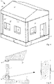
- figure 1 shows schematically the structure of a simple building 10, which is produced by the method according to the invention.
- Figure 1a A cross section through the completed building 10 is shown.
- the building has walls 3 in the
- the walls are essentially formed from foamed polymer material. These walls are a base plate 3', several side walls 3" and a roof 3"'.
- the walls include an envelope 1, which represents an outer skin of the walls 3 in each case.
- This envelope 1 is formed by foil-like material, which is selected depending on the environmental parameters.
- the shell form 1 is formed by an inner shell 11, which is preferably a textile fabric that is similar in feel to wallpaper.
- the envelope 1 is formed by an outer shell 12, which is preferably tailored to the weather conditions of the predefined location.
- the outer shell 12 is preferably formed from a film with a correspondingly high UV resistance; in colder regions, the outer shell 12 will be a waterproof and cold-resistant (frost-resistant foil) foil.
- distance-limiting means 13 in the form of tapes, threads or ropes, which define a maximum distance between the inner shell 11 and the outer shell 12 .
- the distance-limiting means 13 prevent the outer envelope 12 and the inner envelope 11 from moving too far apart. So that the wall thickness of the wall 3 is fixed locally by the distance limiting means 13 .
- Figure 1b shows the in Figure 1a circled section of the wall of the building enlarged. It can be seen that an area foamed with polymer foam 2 is formed between the outer shell 12 and the inner shell. After curing, the foam, in particular together with the enveloping material, provides the stability for the respective wall 3 for the most part.
- the foamed floor panel 3' To stabilize the foamed floor panel 3', it is covered with one or more floor stabilization panels 4, in particular made of wood or plastic; the material of the floor stabilization panel 4 has in particular a higher hardness than the foamed foam material 2 .
- the base plate 3 'and / or the ground stabilization plate 4 is fixed via tie rods 5 in the subsoil 6 of the site.
- a window or door opening 7 is usually already incorporated into the envelope forms during prefabrication, but can also be produced by subsequent sawing out of the hardened foam material.
- the basic structure of the walls 3 is also in figure 2 shown.
- the outer shell 12 and the inner shell 11 are drawn through and fixed by threads or ropes 13' as distance-limiting means or glued, welded or sewn-in tabs or nets 13" as distance-limiting means fixed at their distance in order to achieve a predetermined wall thickness D after foaming with polymer foam 2.
- a variable length of the distance-limiting means between the two outer shells makes this possible also a targeted variability of the wall thickness.
- the wall thickness D can be a few cm (e.g. for furniture) to more than 50 cm (e.g. for thick walls or roofs).
- figure 3 clarifies the function of the distance-limiting means using the example of a reinforced corner of a wall.
- the shape of the corner and thus the course of the distance between the outer shell 12 and the inner shell 11 is set in a targeted manner by means of distance limiting means 13 of different lengths.
- the polymer foam is injected into the intermediate space via inlet openings 9, in particular inlet valves, which are inserted into the shell at specific intervals.
- the polymer foam spreads as a result of the expansion and sticks to the material of the shell mold.
- the degassing occurs through diffusion through the shell or through degassing valves (not shown) used in the shell.
- FIG 4 shows a building 10, which is produced using several separate individual envelope forms 1', 1", 1′′′.
- the envelope form 1' for the base plate 3', the envelope form 1" for the side walls 3" and the envelope form 1" for the roof 1" are connected to each other at interfaces 14 on site before the foam material is filled in.
- the interfaces 14 enable separate envelope forms to be easily connected to one another in a wide variety of combinations.
- detachable, in particular linear, closure systems 14 are used, in particular the zipper or Velcro.
- closure systems 14 allow the individual casing forms to be quickly connected to one another and also released again (in the event of incorrect assembly).
- the casing form is then filled with the foam and the foam hardens, e Despite the detachable locking system, the arrangement retains its permanent stability.
- closure systems are used that have elements designed to be complementary to one another.
- a zipper has, for example, two side parts with matching staples, which are therefore equipped to complement each other; through the targeted use of closure systems with mutually complementary elements can be achieved that the shell forms for individual walls can only be correctly connected to each other.
- the closure system 14 between the roof and the side wall thus has different elements than the closure system between the roof and the floor panel.
- An incorrect assembly for example a connection of the envelope 1′′′ for the roof 3′′′ with the envelope 1′′′ for the base plate 3′′ is thus excluded and can save valuable time in the event of a disaster.
- figure 5 shows in detail, as an example, the enveloping form 1' for the base plate 3' with the enveloping form 1" for the side wall 3" and the enveloping form 1" for the side wall 3" with the enveloping form 1′′′ for the roof 3' via different circumferential zippers , adhesive or Velcro strips 14′, 14′′ are connected to one another.
- a common interior space which is formed by several individual casing forms, foamed out.
- figure 6 shows the modular combination of individual building parts 15 to form a larger building, for example a school or a hospital.
- a building part 15' has been filled with foam
- the enveloping form of the floor 3' of the first building part 15' is connected to the not yet foamed enveloping form 1' of the floor of the next second building part 15" by means of a zipper (or a Velcro or adhesive connection) 14'.
- any intermediate spaces 16 between the building parts 15 are sealed with tabs, for example with an adhesive tape 17; then the intermediate spaces 16 are also foamed with polymer foam (the figure 6 intersects the walls of the two buildings at the location of a passage 7 between the parts of the building).
- the procedure for connecting the roofs 3′′′ of the two parts of the building 15 is corresponding.
- the buildings 10 produced in this way are comparatively light and are secured to the ground, which is based on the figure 7 will be shown.
- the buildings are anchored in the subsoil 6 with tie rods 5, here as hinged anchors 5' or dowels 5".
- An anchor plate 18 is placed on the upper side of the base plate 3', against which the tie rod is screwed.
- the anchor plate 18 distributes the compressive forces that arise evenly onto the surface of the comparatively soft base plate 3'.
- the base plate 3' can also be filled with ballast material 19, which is also filled into the enveloping mold when it is foamed. Fine-grained material with a grain size of less than 2 mm, for example sand, is suitable as ballast material The stability is increased here.
- FIG 8 shows a further development figure 7 .
- the fixings via tie rods 5 in the base 6 also allow the surface of the base plate 3' to be designed during foaming in such a way that a flat base surface is produced, even if the base 6 is not flat.
- the tie rods 5 are set in such a way that formwork panels 21 fastened to them lie in a common horizontal plane.
- the formwork panels 21 are then fastened to the tie rods above the floor to be foamed by means of cross braces 20; the formwork panels 21 keep the surface of the floor panel 3' horizontal and level until it hardens.
- the cross braces 20 and the formwork panels 21 are then dismantled and reused when the next building is produced.
- the tie rods are shortened accordingly by removing intermediate pieces or using a cut-off grinder.
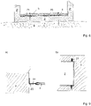
- the Figure 9a illustrates how windows or doors 7 are inserted into the wall 3 with the aid of zip fasteners 22 and sewn, welded or glued tabs 23 .
- the tab with the zipper is attached to the casing 1.
- the windows 7 are formed from a film of transparent material and can be provided with a privacy screen (eg attached by a Velcro strip).
- a simple hinge can be formed by one or more rods 24 which are simply inserted into the foam wall 3 and to which the pane is fixed.
- thin plates e.g. plastic or HDF
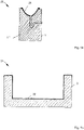
- floor stabilization plates 4 are glued onto the foamed floor plate 3' as floor stabilization plates 4 to distribute the pressure load:
- High-strength casing forms 1′′′ which are in particular fiber-reinforced, for example by Kevlar or similar fibers 26, and/or are provided with force-distributing elements, here a fitting 35.
- Bottom corners can, for example, be glued, welded or sewn on fabric made of high-strength fibers or Reinforced with metal mesh or secured against animal damage.
- the base plate has such a large wall thickness that the building is able to float.
- the building can be attached to tie rods or other fixed, stationary objects by chains or ropes and/or the building can be secured against floating away by guides. This design provides survival space for people and animals in flood areas. After the water has run off, the building sinks back to the ground.
- figure 12 A simplified version without a base plate, in which the side walls are anchored 3" in the ground, is shown figure 12 .
- figure 13 shows another version as a round arch with foam filling, with tie rods 5, front and rear wall 3" and roller door 27.
- FIG 14 shows this using the example of a washbasin 28.
- a wall 3"" is produced by foaming, as already described.
- a washbasin molded part 29 is glued to the wall 3"";
- a drain pipe 30 is already integrated in the enveloping form 1 before the foaming and is automatically laid in the wall 3′′′′ by the foaming.
- the casing for the washbasin can also be connected to the casing for the base plate via a locking system that has been described.
- FIG 15 shows an embodiment of a water basin 31, for example a bathtub, a therapy pool or a (drinking) water reservoir.
- the watertightness is achieved by a glued-in sealing layer 32, in particular a rubber layer or plastic film.
- figure 16 shows a table 33 as another example of a foam-filled piece of furniture. Furnishings of this type, which require a high degree of precision in their shape, are foamed with the additional use of casing 34, which fixes the object in the critical dimensions until it hardens.
- the cover form 1 for the table is kept in shape by the formwork 34 made of wood, cardboard or plastic, for example. After foaming, the casing 34 can be removed and the casing can be reused for the next table.
- Such formwork is also used in the foaming for other wall areas where a special Dimensional accuracy is required, e.g. for window and door openings.
- figure 17 shows examples of other furnishings that can be created in this way, such as a table with additional stabilizing struts ( Figure 17a ), a chair ( Figure 17b ), a chair ( Figure 17c ), a shelf ( Figure 17d ) and a bed ( Figure 17e ) with a recess for a mattress.
- a table with additional stabilizing struts Figure 17a
- a chair Figure 17b
- a chair Figure 17c
- a shelf Figure 17d
- Figure 17e a bed with a recess for a mattress.
- figure 18 shows a top view of a section of a cover mold 1 formed from several individual cover molds 1'-1′′′ ⁇ .
- the individual individual cover molds are each connected to one another by zippers 22.
- the following is based on the Figures 18-22 on the zip fasteners, which connect a first individual casing 1' with a second and a third individual casing 1", 1′′′.
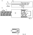
- a basically known zip fastener comprises two side parts 41, each with side part ends 51 (see FIG figure 19 ), and a slider 42.
- the slider 42 encompasses the side parts 41 and is pushed along the side parts 41 in the sliding direction S to close it.
- the zip fasteners which are not explained in any more detail here, are engaged or disengaged from one another during the displacement.
- a zip fastener as is known from a piece of clothing, for example, has an end piece on the side part ends 51 which encompasses both side parts and ensures that the side part ends 51 and thus the side parts 41 do not become detached from one another during use.
- the side parts 41 ', 42 “, 43 ′′′ are in the area of a T-junction 43, such as Figure 20a shows in detail offset from one another in such a way that the mutually corresponding side part ends 51, 51 are not aligned with one another or are arranged offset with respect to one another.
- end pieces 43, 44, 45 are provided which encompass the side parts 41 and are placed on the respective ends of the closed zipper after the respective zipper has been closed.
- a "closed zip fastener” refers to a section of two mutually complementary side parts 41 which engage with one another, as is the case, for example, in Figure 19b and figure 20 , right part.
- Such end pieces can be designed as I-end pieces 44, T-end pieces 43 or X-end pieces 45.
- Figure 19a and 19b shows an example of a longitudinal section through an end piece 44, here an I-end piece 44.
- the end piece has a receiving space 46 for receiving the side parts 41.
- the end piece has an enlarged receiving area 47 and a reduced receiving area 48 adjacent thereto.
- the enlarged one Receiving area 47 can receive end portions 52 of side panels when the associated zipper is open at this point ( Figure 19a ).
- the reduced receiving area 47 can receive end areas 52 of side parts when the associated zipper is closed at this point ( Figure 19b ). This feature is applicable to all types of end pieces.
- an end piece can have several separate receiving spaces 46', 46'' for side parts. Side parts of different zippers can be received in each receiving space. figure 20 shows such a possibility.
- Figure 20a shows a section through the T-end piece 43 figure 18 , top view.
- the Figures 20b and 20c show the T-end piece in a side view, viewed from the right in the sliding direction S.
- the first side part 41' runs through the first receiving space 46' of the end piece 43; the side parts 41′′ and 41′′ each end in the T-end piece 43.
- Two enlarged receiving areas 47 and a reduced receiving area 48 lying between them can be seen in the first receiving space 46.
- the figure 20 11 shows an example in which the corresponding side part ends 51 are not aligned with each other (the side part ends of the side part 41' are out of the picture here) in the slide fastener in the accommodation space 46'.
- the two corresponding side part ends 52* are aligned with one another.
- the closed zipper can provide a sufficiently high level of tightness.
- a comparatively high viscosity of the foam and rapid curing have a positive effect; some leakage is acceptable.
- the tightness may not be sufficient without further measures. The end pieces can contribute to improving the tightness here.
- a bolt may be provided, for example in the form of a needle 51 inserted through it, which secures the position of the end piece relative to the side part ( figure 18 , 20b, 20c ).
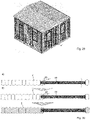
- the slide 42 can be connected to an end piece 43, 44, 45 via a safety mechanism which prevents the slide 42 from being accidentally removed from the end piece.
- a safety mechanism which prevents the slide 42 from being accidentally removed from the end piece.
- Figure 21a shows a longitudinal section parallel to the sliding direction S
- Figure 21b shows a partially sectioned plan view.
- the slide 42 has a barb 49 which engages behind a securing surface 50 of the end piece 44 .
- the barb can also be attached to the end piece 44 and the securing surface to the slide 42 .
- This securing principle is also suitable for other types of end pieces.
- An inner surface of the receiving area of the end piece can be provided with a material 61 which increases friction ( figure 22 ).
- a material 61 which increases friction ( figure 22 ).
- rubber-like materials can be used, which cling to the side part 41 and prevent the side part 41 from slipping out of the end pieces.
- the friction-increasing material 61 supports the insertion of the side part, but prevents it from being removed.
- fibers can be used which are arranged in such a way that they point away from an opening, such as in FIG figure 22 is shown. Plastic or fabric surfaces with a "fur character" and a strong “dash line” are particularly suitable. Fibers, such as hair or wires, can act like a barb.
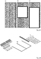
- figure 23 shows one way in which fixed structural elements 53, explained here using a wooden post as a representative, are integrated into the production of the building.
- a wooden post 53 in Figure 23a two initially free-standing wooden posts 53 can be seen, as well as a first individual envelope 1'.
- the wooden post 53 is introduced through an opening 55 into the individual shell mold 1'.
- a second individual casing 1" is connected to the first individual casing 1' by at least one zipper 22, e.g. two zippers or a circumferential zipper.
- the two individual casings 1', 1" now delimit a receiving space in which the wooden post 53 is accommodated ; the opening 55 is thus closed.
- This receiving space is now filled with foam to form a wall 3 ( Figure 23c ).
- the wooden post 53 is surrounded by the foamed material and can increase the stability of the wall 3 produced.
- FIG 24 shows the almost identical process sequence, for example for a corner piece.
- the second individual casing 1" can be formed by a narrow strip which closes the opening 55 of the first individual casing 1'.
- This narrow strip 1" can also be formed integrally with the first individual casing 1'.
- figure 25 shows different side parts as walls. Closed side parts ( Figure 25a ), side panels with a window frame ( Figure 25b ) or side panels with a door frame ( Figure 25c ) are formed.
- Structural elements 53 projecting upwards for example wooden posts or metal rods, are now arranged on the floor ( figure 27 ).
- side wall 3 can be prepared as based on the figure 23 was described.
- figure 28 shows that a roof construction is applied to the structural elements for the side walls.
- the walls of the roof can accordingly figure 23 getting produced.
- figure 29 shows the completed building with roof parts and side parts.
- the order in which the side parts and the roof parts are mounted is arbitrary.
- edge strips 54 are preferably attached to edges of the walls.
- figure 30 shows a modification of the process steps figure 23 .
- the structural element 53 is now a window or door frame.
- the second casing in the form of a tab 1" is attached to the structural element 53, for example glued on.
- the structural element 53 is partially inserted through the opening 55 into the first individual casing.
- the opening 55 is then closed by means of a zipper 22 and the subsequent foaming.
- figure 31 shows a possibility for attaching a second structural part 53" to a first structural part 53', which is already surrounded by an enveloping form 1 and in particular foamed around it.
- the second structural part 53' is placed on the enveloping form 1 and then the two structural parts 53', 53" are screwed together with a screw 56.
- the screw 56 penetrates the casing mold 1 and in particular the foamed material 2.
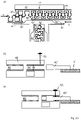
- the foaming material is stored in a reservoir 58 .
- the material is pumped into lines 60 by means of a pump 59 .
- the lines 60 are connected to inlet valves 57 on the shell mold 1 .
- a first quantity of foaming material is conveyed into the casing mold 1 via a lower inlet valve.
- the filled-in material of the first amount then hardens.
- a second quantity of foaming material is then conveyed into the same casing mold through an inlet valve located above.
- the filled-in material of the second quantity then hardens. This process is repeated until the casing mold 1 is completely filled.
Landscapes
- Engineering & Computer Science (AREA)
- Architecture (AREA)
- Physics & Mathematics (AREA)
- Electromagnetism (AREA)
- Civil Engineering (AREA)
- Structural Engineering (AREA)
- Building Environments (AREA)
- Casting Or Compression Moulding Of Plastics Or The Like (AREA)
Description
- Die Erfindung betrifft ein Verfahren zum Verfahren zum Herstellen eines Gebäudes.
- In Katastrophengebieten ist die Herstellung von Unterkünften aufgrund schlechter Infrastruktur und Erreichbarkeit oft mühsam. Der Aufbau von Lazaretten, Unterkünften und sonstigen Einrichtungen sowie deren Einrichtung gestaltet sich daher oft schwierig. Wenn in kurzer Zeit und mit einem Minimum an Transportaufwand Gebäude errichten errichtet werden sollen, durch welche Menschen oder Ausrüstung vor Witterung, Ungeziefer und sonstigen Umwelteinflüssen geschützt werden sollen, kommen zumeist Zelte oder aus Fertigteilen zusammengesetzten provisorische Gebäude zum Einsatz.
- Zelte sind zwar leicht und schnell aufzubauen, bieten aber nur einen begrenzten Witterungsschutz, isolieren schlecht, schützen nicht vor Ungeziefer, haben eine geringe Lebensdauer und erlauben kaum eine Privatsphäre. Aus Fertigteilen zusammengesetzte Gebäude bieten zwar einen besseren Komfort und haben eine höhere Lebensdauer; aufgrund der zumeist sperrigen Einzelteile haben sie aber ein großes Transportvolumen und oft ein beträchtliches Transportgewicht.
- Die
DE 196 50 219 A1 offenbart ein Bauteil mit einer unter Zugspannung stehenden Bewehrung, die mit einer Druckspannungen aufnehmenden Masse verbunden ist. Die Bewehrung besteht aus einer Hülle aus einem nicht metallischen bahnförmigen Material, die Masse ist ein ausgehärteter Schaumstoff. Die Hülle umhüllt den Schaumstoff. Die einander berührenden Flächen von Hülle und Schaumstoff, die in Richtung der Zugspannung der Hülle verlaufen, sind miteinander verbunden. - Die
DE 10 2009 049 298 A1 offenbart ein Verfahren zur Herstellung von solchen Fertigteilen, die aus einem aufgeschäumten Polymermaterial gebildet sind. - Ferner existiert eine Vielzahl von Ideen zum Aufbau von Notunterkünften, die aber bislang nicht umgesetzt wurden. So offenbart die
DE 102 58 542 B4 eine Notunterkunft, die in einen Fallschirm integriert ist. Beim Abwurf des Fallschirms werden Kammern des Fallschirms durch einen selbsthärtenden Schaum ausgefüllt, welcher während des Fluges aushärtet; der landende Fallschirm stellt dann das fertige Gebäude dar. - Die Aufgabe der vorliegenden Erfindung ist es, robuste Gebäude und ggf. darin zu verwendende Einrichtungsgegenstände auf eine schnelle und kostengünstige Weise auch in schwer zu zugänglichen Einsatzgebieten bereitzustellen.
- Die der Erfindung zugrunde liegende Aufgabe wird gelöst durch ein Verfahren nach Anspruch 1. Vorteilhafte Ausgestaltungen ergeben sich aus den Unteransprüchen und der nachfolgenden Beschreibung.
- Der Kern der Erfindung liegt nun insbesondere darin, ein Gebäude durch Ausschäumen der Hüllform am Einsatzort selbst herzustellen. Die Hüllform weist vor dem Ausschäumen ein geringes Gewicht auf und ist flexibel verpackbar. Daher ist die Hüllform ideal zu transportieren. Das Schaummaterial kann zunächst in beliebig großen Tankeinrichtungen platzsparend an den vordefinierten Standort transportiert werden; die ausgeschäumte Wandung weist, verglichen mit einer Wandung aus Fertigpaneelen, ein recht geringes spezifisches Gewicht auf; somit ist auch stabilisierende Baumaterial ideal zu transportieren. Die flexible Hüllform wird zumindest teilweise um zumindest ein festes Strukturelement herum angeordnet und das feste Strukturelement von dem schäumenden Material zumindest teilweise umschlossen.
- Das so hergestellte Gebäude weist somit ein hohes Maß an Widerstandsfähigkeit gegenüber Erdbeben und Witterung auf, und kann dabei insbesondere wirksam vor Hitze, Kälte und Lärm schützen. Eine Lebensdauer von mindestens 5-10 Jahren ist möglich; das Gebäude kann in etwa den Komfort eines einfachen Hauses bieten. Die Entsorgung ist über eine Verbrennungsanlage oder durch chemisches Recycling unproblematisch möglich.
- Dabei wird die Hüllform vorzugsweise vor dem Ausschäumen oder während des Ausschäumens dauerhaft am vordefinierten Standort fixiert oder es wird die ausgeschäumte Wandung unmittelbar nach dem Aushärten am vordefinierten Standort fixiert. Insbesondere kann das schäumende Material während des Aushärtens eine dauerhafte Verbindung mit dem Untergrund am vordefinierten Standort eingehen. Vorzugsweise wird eine Bodenplatte mit einer waagerecht ausgerichteten Oberseite auf einer unebenen Oberfläche des vordefinierten Standortes erzeugt. Das Schaummaterial gleicht hierbei Unebenheiten des Untergrundes aus; auf der Oberseite kann durch eine Verschalung die waagerechte ebene Fläche hergestellt werden. Somit können auch an leicht- bis mittelstarken Hanglagen oder auf felsigem Untergrund auf einfache Weise solche Gebäude erzeugt werden.
- Die flexible Hüllform, einschließlich etwaiger separater Einzelhüllformen, aus denen eine größere Gesamthüllform gebildet werden kann, wird vorzugsweise vorgefertigt an den vordefinierten Standort transportiert und wird dort ausgeschäumt. Da die Hüllform vor Ort lediglich auszuschäumen ist, werden Fehler bei der Arbeit vor Ort weitgehend vermieden.
- Vorzugsweise weist die Hüllform eine flexible Außenhülle und eine flexible Innenhülle auf, wobei zwischen der Außenhülle und der Innenhülle ein Aufnahmeraum für das schäumende Material gebildet ist. Die Außenhülle stellt insbesondere eine wetterzugewandte Außenfläche des Gebäudes bildet und ist insbesondere aus einem wetterfesten, wasserabweisenden und/oder UV-beständigen Material gebildet. Bei der Auswahl des Materials ist der Einsatzort und der Einsatzzweck zu berücksichtigen, insbesondere im Hinblick auf die erwartete Einsatzdauer und die zu erwartenden Belastungen. Bei hohen mechanischen Belastungen können faserverstärkte Materialien zum Einsatz kommen. Die Innenhülle stellt insbesondere eine Innenfläche eines Zimmers des Gebäudes bereit. Insofern kann die Innenhülle eine haptisch angenehme Oberfläche aufweisen, beispielsweise aus textilem Material.
- Zwischen der Außenhülle und der Innenhülle sind Abstandbegrenzungsmittel angeordnet, die eingerichtet sind, örtlich eine maximale Wandstärke der Wandung zu definieren. Durch die Abstandbegrenzungsmittel wird folglich der Grad der Ausschäumung örtlich begrenzt, so dass zu große Wandstärken vermieden werden; dies kann analog zur Ausgestaltungen von Hüpfburgen oder aufblasbaren Zelten erfolgen. Durch die Abstandbegrenzungsmittel können der Hüllform auch Formen aufgeprägt werden, beispielsweise Kurven und Ecken.
- Vorzugsweise ist eine Hüllform durch eine Mehrzahl von Einzelhüllformen gebildet, wobei eine zweite der Einzelhüllformen vor deren Ausschäumen über ein Verschlusssystem mit einer ersten der Einzelhüllformen verbunden wird. Die Verbindung der beiden Einzelhüllformen kann dabei erfolgen, solange die zweite Einzelhüllform noch nicht ausgeschäumt ist; die erste Einzelhüllformen kann, muss aber nicht, bereits ausgeschäumt sein. Durch die Möglichkeit, Einzelhüllformen zu einer Gesamthüllform zu verbinden, ergeben sich vielfältige Möglichkeiten, aus einer begrenzten Auswahl von Einzelhüllformen auf individuelle Weise eine Vielzahl unterschiedliche Gebäude zu gestalten. Die Gestalt kann sogar vor Ort durch Auswahl der Einzelhüllformen beeinflusst werden. Insbesondere die Größe der Gebäude lässt sich somit vor Ort an die Gegebenheiten anpassen.
- Vorzugsweise weist ein erstes Verschlusssystem zur Verbindung der Hüllform einer ersten Wandung mit der Hüllform einer zweiten Wandung unterschiedliche Verschlusselemente auf als ein zweites Verschlusssystem zur Verbindung der Hüllform der zweiten Wandung mit der Hüllform einer dritten Wandung. Insbesondere handelt sich bei diesen drei genannten unterschiedlichen Wandungen um unterschiedliche Arten von Wandungen, insbesondere Bodenplatte, Seitenwandung und Dach. Durch den Einsatz unterschiedlicher Verschlusselemente, beispielsweise Reißverschlüsse unterschiedlicher Größe, können nur zueinander passende Hüllformen miteinander verbunden werden; eine Fehlmontage vor Ort kann damit vermieden werden.
- Als Verschlusssystem wird insbesondere ein Reißverschluss oder ein Klettverschluss verwendet. Wenn das Verschlusssystem insbesondere vor dem Ausschäumen zunächst noch lösbar ist, kann die genaue Gestalt der Hüllform bis zum endgültigen Ausschäumen oder Aushärten noch verändert werden.
- Alternativ kann ein Klebeverfahren zum Verbinden der Einzelhüllformen verwendet werden.
- Vorzugsweise wird ein geschlossener Reißverschluss durch zwei Seitenteile gebildet, die miteinander in Eingriff gebracht werden. Nach dem in Eingriff bringen wird ein Endstück über ein Ende des geschlossenen Reißverschlusses geführt, wobei das Endstück zumindest ein Seitenteilende des geschlossenen Reißverschlusses umgreift. Das Endstück kann damit das unbeabsichtigte Öffnen des Reißverschlusses verhindern, was bei einem handelsüblichen Reißverschluss (z.B. an einer Jacke) durch ein Anfangsstück gewährleistet ist. Solche Anfangsstücke können, wie noch ausgeführt wird, im vorliegenden Anwendungsfall teilweise nicht verwendet werden.
- Insbesondere ist das nachträgliche Anbringen des Endstücks sinnvoll, wenn das Endstück genau ein Seitenteilende des geschlossenen Reißverschlusses umgreift. Insbesondere ist dies vorteilhaft, falls die einander entsprechenden Seitenteilenden der beiden Seitenteile in Schieberichtung versetzt zueinander angeordnet sind. Was hierunter zu verstehen ist wird anhand der
Figur 20a deutlich. - Vorzugweise umfasst der Reißverschluss einen Schieber, mit dessen Hilfe der Reißverschluss aus einem geöffneten Zustand in einen geschlossenen Zustand, überführbar ist, wobei der Reißverschluss ein Verriegelungsmittel umfasst, welche den Schieber in einer einer Endstellung, insbesobdere bei geschlossenem Reißverschluss, gegen ein unbeabsichtiges Lösen aus dieser Endstellung sichert.
- Erfindungsgemäß wird die flexible Hüllform zumindest teilweise um zumindest ein festes Strukturelement herum angeordnet und das feste Strukturelement wird von dem schäumenden Material zumindest teilweise umschlossen. Hiermit kann auf einfache Art die Stabilität des Gebäudes erhöht werden. Das feste Strutkturelement kann dabei untrennbarer Bestandteil der geschäumten Wand werden.
- Vorzugsweise liegt dabei das feste Strukturelement zunächst frei, anschließend wird das Strukturelement zumindest teilweise durch eine Öffnung der Hüllform zumindest teilweise in die Hüllform eingbracht und anschließend wird die Öffnung in der Hüllform verschlossen, insbesodere durch Verbinden zweier Einzelhüllformen. Dies kann auf die vorgenannte Art duchgeführt werden.
- Vorzugsweise wird eine erste Menge an schäumenden Material in die Hüllform zunächst in einen unteren Bereich eingefüllt, anschließend härtet die erste Menge zumindest teilweise aus. Anschließend wird in die Hüllform eine zweite Menge an schäumendem Material auf die erste Menge des schäumenden Materials eingefüllt. Diese Vorgehensweise ermöglicht einen gleichmäßigen Aufbau der Wandung über deren gesamte Höhe. Dabei wird vermieden, dass noch nicht ausgehärtetes Material während des Aushärtes zu sehr unter Druck gesetzt wird durch darüberliegendes Material.
- Durch das vorbeschriebene Verfahren können auch Wandungen gebildet werden, die Bestandteil von beweglichen oder fest installierten Einrichtungsgegenständen sind. So können Einrichtungsgegenstände wie Möbel und Sanitäranlagen durch Ausschäumen einer entsprechenden Hüllform gebildet werden. Dabei kann eine entsprechende Hüllform vor deren Ausschäumen über ein Verschlusssystem wie beschrieben mit einer anderen Hüllform von Gebäudewandungen verbunden werden.
- Um mechanisch stark belastete, Bereiche von Wandungen zu schonen, werden diese durch Verstärkungselemente, beispielsweise Beschläge, wie Leisten, Platten, oder besonders feste Hüllmaterialien verstärkt.
- Die Erfindung betrifft ferner ein Verfahren zum Herstellen und Entsorgen eines Gebäudes, umfassend das Herstellen eines Gebäudes wie vorbeschrieben, ferner ein Zerkleinern der Wandungen und anschließend Zuführen der zerkleinerten Wandungen einem Verbrennungs- oder Recyclingprozess. Auch der Entsorgungsprozess ist recht einfach und kann über örtlich vorhandene Anlagen erfolgen.
- Die Erfindung wird anhand der Figuren nachfolgend näher erläutert; hierin zeigt:
- Figur 1
- a) ein erfindungsgemäß hergestelltes Gebäude im Querschnitt; b) eine Vergrößerung eines Teils des Querschnitts nach
Figur 1a ; - Figur 2
- ein weiterer Querschnitt einer Wandung mit dargestellten Abstandbegrenzungsmitteln;
- Figur 3
- ein weiterer Querschnitt einer Wandung mit dargestellten Abstandbegrenzungsmitteln an einer Ecke der Wandung;
- Figur 4
- eine weiteres erfindungsgemäß hergestelltes Gebäude in perspektivischer Darstellung;
- Figur 5
- Einzelheiten der Wandungen mit eingezeichneten Verschlusssystemen im Querschnitt;
- Figur 6
- ein Querschnitt von Wandungen mit Verschlusssystem zur Verbindung mehrerer Gebäudeteile;
- Figur 7
- eine Bodenplatte mit Zugankern zur Fixierung im Untergrund im Querschnitt;
- Figur 8
- eine ausgeschäumte Bodenplatte mit Verschalung im Querschnitt;
- Figur 9
- a) eine Reißverschlussbefestigung eines Fensters in einer Wandung im Querschnitt; b) eine Scharnierbefestigung eines Fensters in einer Wandung im Querschnitt;
- Figur 10
- eine Bodenstabilisierungsplatte im Querschnitt;
- Figur 11
- eine Faserverstärkung für das Dach im Querschnitt;
- Figur 12
- eine Verankerung der Seitenwandung im Untergrund im Querschnitt;
- Figur 13
- eine erfindungsgemäß hergestellte Lagerhalle im Querschnitt;
- Figur 14
- ein erfindungsgemäß hergestellter Waschtisch;
- Figur 15
- ein erfindungsgemäß hergestelltes Wasserbecken;
- Figur 16
- eine geschäumter Tisch mit Verschalung im Querschnitt;
- Figur 17
- weitere geschäumte Einrichtungsgegenstände;
- Figur 18
- einen Ausschnitt einer aus mehreren Einzelhüllformen gebildet Hüllform;
- Figur 19
- ein Endstück für einen Reißverschluss im Längsschnitt;
- Figur 20
- eine T-Verbindungsstelle der Hüllform aus
Figur 18 in Einzelheit in verschiedenen Ansichten; - Figur 21
- eine Anordnung aus Schieber und Endstück im Reißverschluss in verschiedenen Ansichten;
- Figur 22
- Details eines Endstücks im Längsschnitt;
- Figur 23
- Verfahrensschritte beim Ausschäumen der Hüllform;
- Figur 24
- eine Abwandlung der Verfahrensschritte nach
Figur 23 ; - Figur 25
- beispielhaften Ausgestaltungen von Wandungen;
- Figur 26
- schematisch einen ersten Verfahrensschritt bei der Herstellung einer Wandungen
- Figur 27-29
- schematisch unterschiedliche Verfahrensschritte bei der Herstellung eines Gebäudes;
- Figur 30
- eine Abwandlung der Verfahrensschritte nach
Figur 23 ; - Figur 31
- schematisch die Verfahrensschritte zum Verbinden zweiter Strukturelemente;
- Figur 32
- die Reihenfolge beim Befüllen einer Hüllform.
-
Figur 1 zeigt schematisch den Aufbau eines einfachen Gebäudes 10, welches durch das erfindungsgemäße Verfahren hergestellt wird. InFigur 1a ist ein Querschnitt durch das fertiggestellte Gebäude 10 gezeigt. Das Gebäude weist Wandungen 3 auf, die im - Wesentlichen aus aufgeschäumten Polymermaterial gebildet sind. Diese Wandungen sind eine Bodenplatte 3', mehrere Seitenwände 3" und ein Dach 3"'. Die Wandungen umfassen eine Hüllform 1, welche jeweils eine Außenhaut der Wandungen 3 darstellt. Diese Hüllform 1 ist durch folienartiges Material gebildet, welches je nach Umgebungsparameter ausgewählt wird. An der Innenseite, also der einem Innenraum des Gebäudes zugewandten Seite, ist die Hüllform 1 durch eine Innenhülle 11 gebildet, die bevorzugt ein textiles Gewebe ist, das von der Haptik einer Tapete ähnelt.
- An der Außenseite, also der der Außenumgebung des Gebäudes zugewandten Seite, ist die Hüllform 1 durch eine Außenhülle 12 gebildet, die bevorzugt auf die Wetterbedingungen des vordefinierten Standortes abgestimmt ist. In sonnigen Gebieten wird die Außenhülle 12 bevorzugt aus einer Folie mit entsprechend hoher UV-Beständigkeit gebildet sein; in kälteren Gebieten wird die Außenhülle 12 eine wasserdichte und kältebeständige (frostbeständige Folie) Folie sein. Zwischen der Innenhülle 11 und der Außenhülle 12 sind Abstandbegrenzungsmittel 13 in Form von Bändern, Fäden oder Seilen vorgesehen, die einen Maximalabstand zwischen der Innenhülle 11 und der Außenhülle 12 definieren. Beim Ausschäumen der Hüllform 1, was weiter unten noch näher erläutert wird, verhindern die Abstandbegrenzungsmittel 13, dass sich die Außenhülle 12 und die Innenhülle 11 zu weit voneinander entfernen. Damit wir durch die Abstandbegrenzungsmittel 13 örtlich die Wandstärke der Wandung 3 festgelegt.
-
Figur 1b zeigt den inFigur 1a eingekreisten Ausschnitt der Wandung des Gebäudes vergrößert. Zu erkennen ist, dass zwischen der Außenhülle 12 und der Innenhülle ein mit Polymerschaum 2 ausgeschäumter Bereich gebildet ist. Nach einem Aushärten stellt größtenteils der Schaum, insbesondere zusammen mit dem Hüllmaterial, die Stabilität für die jeweilig Wandung 3 bereit. - Zur Stabilisierung der geschäumten Bodenplatte 3' ist diese mit einer oder mehreren Bodenstabilisierungsplatten 4, insbesondere aus Holz oder Kunststoff bedeckt; das Material der Bodenstabilisierungsplatte 4 weist insbesondere eine höhere Härte als das ausgeschäumte Schaummaterial 2 auf. Die Bodenplatte 3' und/oder die Bodenstabilisierungsplatte 4 ist über Zuganker 5 fest im Untergrund 6 des Standortes befestigt. Eine Fenster- oder Türöffnung 7 wird in der Regel bereits in der Vorfertigung in die Hüllformen eingearbeitet, kann jedoch auch durch nachträgliches Aussägen aus dem ausgehärteten Schaummaterial erzeugt werden.
- Der prinzipielle Aufbau der Wandungen 3 ist ferner in
Figur 2 dargestellt. Die Außenhülle 12 und die Innenhülle 11 werden durch durchgezogene und fixierte Fäden oder Seile 13' als Abstandsbegrenzungsmittel oder eingeklebte, eingeschweißte bzw. eingenähte Laschen oder Netze 13" als Abstandsbegrenzungsmittel in ihrem Abstand fixiert, um nach dem Ausschäumen mit Polymerschaum 2 eine vorbestimmte Wandstärke D zu erreichen. Eine variable Länge der Abstandsbegrenzungsmittel zwischen den beiden Außenhüllen ermöglicht dabei auch eine gezielte Variabilität der Wandstärke. Die Wandstärke D kann wenige cm (etwa für Möbel) bis über 50cm (etwa für starke Wände oder Dächer) betragen. -
Figur 3 verdeutlicht die Funktion der Abstandbegrenzungsmittel am Beispiel einer verstärkten Ecke einer Wandung. Der Form der Ecke und damit ein Verlauf des Abstandes der Außenhülle 12 zur Innenhülle 11 wird durch verschieden lange Abstandbegrenzungsmittel 13 gezielt eingestellt. - Der Polymerschaum wird über in die Hülle in bestimmten Abständen eingesetzte Einlassöffnungen 9, insbesondere Einlassventile, in den Zwischenraum eingespritzt. Der Polymerschaum verteilt sich durch die Expansion und verklebt mit dem Material der Hüllform. Die Entgasung dabei durch Diffusion durch die Hülle hindurch oder durch in der Hülle eingesetzte, nicht dargestellte Entgasungsventile.
-
Figur 4 zeigt ein Gebäude 10, welches anhand mehrerer separater Einzelhüllformen 1', 1", 1‴ hergestellt wird. Die Hüllform 1' für die Bodenplatte 3', die Hüllformen 1" für die Seitenwandungen 3" sowie die Hüllform 1‴ für das Dach 1‴ werden vor dem Einfüllen des Schaummaterials miteinander an Schnittstellen 14 vor Ort miteinander verbunden. So entsteht aus einer Vielzahl von Einzelhüllformen eine Gesamthüllform, die anschließend mit Schaum aufgefüllt werden kann. Die Schnittstellen 14 ermöglichen ein einfaches Verbinden separater Hüllformen miteinander in unterschiedlichsten Kombinationen. Als Schnittstellen 14 kommen im hier lösbare, insbesondere linienförmige, Verschlusssysteme 14 zur Verwendung, insbesondere der Reißverschluss oder der Klettverschluss. Durch solche Verschlusssysteme 14 lassen sich die einzelnen Hüllformen schnell miteinander verbinden und auch wieder lösen (bei fehlerhaftem Zusammensetzen). Wird anschließend die Hüllform mit dem Schaum ausgefüllt und der Schaum härtet aus, erhält die Anordnung trotz des lösbaren Verschlusssystems ihre dauerhafte Stabilität. - Vorzugsweise werden dabei nur solche Verschlusssysteme verwendet, die komplementär zueinander ausgestaltete Elemente aufweisen. Ein Reißverschluss weist z.B. zwei Seitenteile mit zueinander passenden Krampen auf, die somit komplementär zueinander ausgestattet sind; durch den gezielten Einsatz von Verschlusssystemen mit zueinander komplementär ausgebildeten Elementen kann somit erreicht werden, dass die Hüllformen für einzelne Wandungen nur korrekt miteinander verbunden werden können. Das Verschlusssystem 14 zwischen Dach und Seitenwandung weist somit andere Elemente auf als das Verschlusssystem zwischen Dach und Bodenplatte. Eine Fehlmontage, beispielsweise eine Verbindung der Hüllform 1‴ für das Dach 3‴ mit der Hüllform 1' für die Bodenplatte 3", ist somit ausgeschlossen und kann im Katastrophenfall wertvolle Zeit einsparen.
-
Figur 5 zeigt in Einzelheit, wie beispielhaft die Hüllform 1' für die Bodenplatte 3' mit der Hüllform 1" für die Seitenwandung 3" sowie die Hüllform 1" für die Seitenwandung 3" mit der Hüllform 1‴ für das Dach 3' über unterschiedliche, umlaufende Reißverschlüsse, Klebe- oder Klettverschlussbänder 14', 14" miteinander verbunden sind. In einer möglichen Ausgestaltung erfolgt erst nach der Verbindung der einzelnen Hüllformen miteinander ein Ausschäumen eines gemeinsamen Innenraumes, der durch mehrere Einzelhüllformen gebildet ist. -
Figur 6 zeigt den modularen Verbund einzelner Gebäudeteile 15 zu einem größeren Gebäude z.B. einer Schule oder einem Krankenhaus. Nach dem Ausschäumen eines Gebäudeteils 15' wird die Hüllform des Bodens 3' des ersten Gebäudeteils 15' mittels eines Reißverschlusses (oder einer Klett- oder Klebeverbindung) 14' mit der noch nicht ausgeschäumten Hüllform 1' des Bodens des nächsten zweiten Gebäudeteils 15" verbunden. Nach dem Ausschäumen dieses zweiten Gebäudeteils 15' werden etwaige Zwischenräume 16 zwischen den Gebäudeteilen 15 mit Laschen abgedichtet, beispielsweise mit einem Klebeband 17; anschließend werden die Zwischenräume 16 ebenfalls mit Polymerschaum ausgeschäumt (dieFigur 6 schneidet die Wände der beiden Gebäude an der Stelle eines Durchganges 7 zwischen den Gebäudeteilen). Entsprechend wird an der Verbindung der Dächer 3‴ der beiden Gebäudeteile 15 verfahren. - Die so hergestellten Gebäude 10 sind vergleichsweise leicht und werden am Untergrund gesichert, was anhand der
Figur 7 gezeigt wird. Dazu werden die Gebäude im Untergrund 6 mit Zugankern 5, hier als Klappanker 5' oder Dübel 5", verankert. Auf der Oberseite der Bodenplatte 3' ist eine Ankerplatte 18 aufgelegt, gegenüber dem der Zuganker verschraubt wird. Die Ankerplatte 18 verteilt die entstehenden Druckkräfte gleichmäßig auf die Oberfläche der vergleichsweise weichen Bodenplatte 3'. Grundsätzlich kann die Bodenplatte 3' auch mit Ballastmaterial 19 gefüllt sein, welches insbesondere beim Ausschäumen mit in die Hüllform eingefüllt wird. Als Ballastmaterial eignet sich feinkörniges Material mit einer Korngröße von unter 2mm, beispielsweise Sand. Die Standfestigkeit wird hierbei erhöht. -
Figur 8 zeigt eine Weiterbildung zurFigur 7 . Die Fixierungen über Zuganker 5 im Untergrund 6 erlauben auch, die Oberfläche der Bodenplatte 3' beim Ausschäumen so zu gestalten, dass eine ebene Bodenfläche entsteht, selbst wenn der Untergrund 6 nicht eben ist. Hierzu werden die Zuganker 5 derart eingestellt, dass daran befestigte Schalungsplatten 21 in einer gemeinsamen horizontalen Ebene liegen. An den Zugankern werden dann über dem auszuschäumenden Boden die Schalungsplatten 21 mittels Querstreben 20 befestigt; die Schalungsplatten 21 halten die Oberfläche der Bodenplatte 3' bis zum Aushärten waagerecht und eben. Die Querstreben 20 und die Schalungsplatten 21 werden anschließend demontiert und beim Herstellen des nächsten Gebäudes wiederverwendet. Die Zuganker werden durch Herausnahme von Zwischenstücken oder mit einem Trennschleifer entsprechend gekürzt. - Die
Figur 9a verdeutlicht, wie Fenster oder Türen 7 mit Hilfe von Reißverschlüssen 22 und eingenähten, eingeschweißten bzw. eingeklebten Laschen 23 in die Wand 3 eingesetzt werden. Die Lasche mit dem Reißverschluss ist dabei an der Hüllform 1 befestigt. Die Fenster 7 sind aus einer Folie aus transparentem Material gebildet und können mit einem Sichtschutz versehen werden (z.B. durch ein Klettenband befestigt). - Es können auch formstabile Fenster 7, insbesondere auch Glas- oder Kunststoffscheiben, in der Wandung eingesetzt werden, wie anhand der
Figur 9a gezeigt wird. Ein einfaches Scharnier kann durch eine oder mehrere Stangen 24 gebildet werden, die in die Wandung 3 aus Schaum einfach eingesteckt werden und an der die Scheibe befestigt ist. - Anhand der weiteren Figuren wird erläutert, wie stark belastete Bereiche des Gebäudes gezielt verstärkt werden.
- In
Figur 10 sind zur Verteilung der Druckbelastung auf die ausgeschäumte Bodenplatte 3' dünne Platten (z.B.: Kunststoff oder HDF) als Bodenstabilisierungsplatten 4 aufgeklebt: Auf diese Bodenstabilisierungsplatten 4 ist ein Bodenbelag 25, z.B. ein Gummi-, Kunststoff- oder Laminatfußbodenbelag, aufgebracht. - Hoch belastete Trägerbereiche, insbesondere am Dach 3‴ (
Figur 11 ), erfordern hochfeste Hüllformen 1‴, die insbesondere faserverstärkt sind, beispielsweise durch Kevlar- oder ähnliche Fasern 26, und/oder mit kraftverteilenden Elementen versehen sind, hier einem Beschlag 35. Bodenecken können z.B. aufgeklebte, aufgeschweißte oder aufgenähte Gewebe aus hochfesten Faser- oder Metallgeweben verstärkt bzw. gegen Tierfraß gesichert werden. - In einer nicht dargestellten Ausführung der Erfindung weist die Bodenplatte eine derart große Wandstärke auf, dass eine Schwimmfähigkeit des Gebäudes erreicht wird. Durch Ketten oder Seile kann das Gebäude an Zugankern oder anderen festen ortsfesten Gegenständen befestigt werden und/oder das Gebäude kann durch Führungen gegen Wegschwimmen gesichert werden. Diese Ausführung bietet Überlebensraum für Menschen und Tiere in Überschwemmungsgebieten. Das Gebäude sinkt nach Ablaufen des Wassers wieder auf den Untergrund zurück.
- Eine vereinfachte Ausführung ohne Bodenplatte, bei der die Seitenwandungen 3" im Untergrund verankert sind, zeigt
Figur 12 . Eine solche Ausführung ermöglicht den Aufbau von einfachen Garagen und Materiallagern.Figur 13 zeigt eine weitere Ausführung als ausgeschäumter Rundbogen, mit Zugankern 5, Vorder- bzw. Rückwand 3" und Rolltor 27. - Mit Hilfe von vor dem Ausschäumen eingesetzten Formteilen aus Kunststoff, Keramik, Holz oder Metall ist die Herstellung von fest installierten Einrichtungsgegenständen denkbar, Beispiele dafür sind Sanitäreinrichtungen wie Duschen, Toiletten, Waschbecken.
Figur 14 zeigt dies am Beispiel eines Waschtisches 28. Hierbei wird eine Wandung 3"" durch Ausschäumen erzeugt, wie bereits beschrieben. Auf die Wandung 3"" wird ein Waschbecken-Formteil 29 angeklebt; ein Abflussrohr 30 ist bereits vor dem Ausschäumen in der Hüllform 1 integriert und wird durch das Ausschäumen automatisch in der Wandung 3"" verlegt. Auch die Hüllform für das Waschbecken kann über ein beschriebenes Verschlusssystem mit der Hüllform für die Bodenplatte verbunden sein. -
Figur 15 zeigt eine Ausführung eines Wasserbeckens 31, beispielsweise eine Badewanne, ein Therapiebecken oder einen (Trink-)Wasserspeicher. Die Wasserdichtigkeit wird durch eine eingeklebte Dichtlage 32, insbesondere eine Gummilage oder Kunststofffolie, erreicht. -
Figur 16 zeigt einen Tisch 33 als weiteres Beispiel für einen ausgeschäumten Einrichtungsgegenstand. Solche Einrichtungsgegenstände, die für ihre Verwendung eine hohe Formpräzision erfordern, werden unter zusätzlicher Verwendung einer Verschalung 34, die den Gegenstand bis zur Aushärtung in den kritischen Dimensionen fixiert, ausgeschäumt. Die Hüllform 1 für den Tisch wird von der z.B. aus Holz, Pappe oder Kunststoff gefertigten Verschalung 34 in Form gehalten. Nachdem Ausschäumens kann die Verschalung 34 entfernt werden und die Verschalung kann für den nächsten Tisch wiederverwendet werden. Eine solche Verschalung wird auch eingesetzt bei der Ausschäumung für anderer Wandungsbereiche, an denen eine besondere Maßhaltigkeit erforderlich ist, z.B. für Fenster- und Türöffnungen. -
Figur 17 zeigt beispielhaft weitere Einrichtungsgegenstände, die auf diese Weise erzeugt werden können, beispielsweise ein Tisch mit zusätzlichen Stabilisierungsstreben (Figur 17a ), einen Stuhl (Figur 17b ), einen Sessel (Figur 17c ), ein Regal (Figur 17d ) und ein Bett (Figur 17e ) mit einer Vertiefung für eine Matratze. -
Figur 18 zeigt in Draufsicht einen Ausschnitt einer aus mehreren Einzelhüllformen 1'-1‴ʺ gebildeten Hüllform 1. Die einzelnen Einzelhüllformen sind jeweils durch Reißverschlüsse 22 miteinander verbunden. Im Folgenden wird anhand derFiguren 18-22 auf die Reißverschlüsse näher eingegangen, welche eine erste Einzelhüllform 1' mit einer zweiten und einer dritten Einzelhüllform 1", 1‴ verbindet. - Ein grundsätzlich bekannter Reißverschluss umfasst zwei Seitenteile 41, jeweils mit Seitenteilenden 51 (siehe
Figur 19 ), und einen Schieber 42. Der Schieber 42 umgreift die Seitenteile 41 und wird zum Schließen entlang der Seitenteile 41 in Schieberichtung S verschoben. Während des Verschiebens werden je nach Richtung die hier nicht näher erläuterten Krampen des Reißverschlusses in Eingriff bzw. außer Eingriff zueinander gebracht. Ein Reißverschluss, wie man ihn z.B. von einem Kleidungsstück kennt, umfasst an den Seitenteilenden 51 ein Endstück, welches beide Seitenteile umgreift und sicherstellt, dass die Seitenteilenden 51 und damit die Seitenteile 41 sich während der Benutzung nicht voneinander lösen. - Die Seitenteile 41', 42", 43‴ liegen im Bereich einer T-Verbindungsstelle 43, wie
Figur 20a detailliert zeigt, derart versetzt zueinander, dass die einander entsprechenden Seitenteilenden 51, 51 nicht zueinander ausgerichtet sind bzw. versetzt zueinander angeordnet sind. Um dennoch die Seitenteile 41 miteinander dauerhaft zu verbinden, sind Endstücke 43, 44, 45 vorgesehen, welche die Seitenteile 41 umgreifen und dazu nach einem Verschließen des jeweilgen Reißverschlusses auf die jeweiligen Enden des geschlossenen Reißverschlusses aufgesetzt werden. Ein "geschlossener Reißverschluss" bezeichnet dabei einen Abschnitt von zwei zueinander komplementär ausgebildeten Seitenteilen 41, die miteinander in Eingriff sind, wie es beispielsweise inFigur 19b undFigur 20 , rechter Teil, dargestellt ist. Solche Endstücke können als I-Endstücke 44, T-Endstücke 43 oder X-Endstücke 45 ausgebildet sein. -
Figur 19a und 19b zeigt beispielhaft den Längsschnitt durch ein Endstück 44, hier ein I-Endstück 44. Das Endstück weist einen Aufnahmeraum 46 zur Aufnahme der Seitenteile 41 auf. Das Endstück weist einen vergrößerte Aufnahmebereich 47 und ein dazu benachbarten verkleinerten Aufnahmebereich 48 aufweist. Der vergrößerte Aufnahmebereich 47 kann Endbereiche 52 von Seitenteilen aufnehmen, wenn der zugehörige Reißverschluss an dieser Stelle geöffnet ist (Figur 19a ). Der verkleinerte Aufnahmebereich 47 kann Endbereiche 52 von Seitenteilen aufnehmen, wenn der zugehörige Reißverschluss an dieser Stelle geschlossen ist (Figur 19b ). Dieses Merkmal ist auf sämtliche Arten von Endstücken anwendbar. - Ein Endstück kann grundsätzlich mehrere separate Aufnahmeräume 46', 46" für Seitenteile aufweisen. In jedem Aufnahmeraum können Seitenteile unterschiedlicher Reißverschlüsse aufgenommen werden.
Figur 20 zeigt eine solche Möglichkeit. -
Figur 20a zeigt einen Schnitt durch das T-Endstück 43 nachFigur 18 , in Draufsicht. DieFiguren 20b und 20c zeigen das T-Endstück in Seitenansicht, betrachtet von rechts in Schieberichtung S. Das erste Seitenteil 41' läuft dabei durch den ersten Aufnahmeraum 46' des Endstücks 43 hindurch; die Seitenteile 41" und 41" enden jeweils im T-Endstück 43. Es sind zwei vergrößerte Aufnahmebereich 47 und ein dazwischenliegender verkleinerter Aufnahmebereich 48 im ersten Aufnahmeraum 46 zu erkennen. - Zudem endet hier im T-Endstück im zweiten Aufnahmeraum 46" ein weiterer geschlossener Reißverschluss, welcher mit deren jeweiligen Seitenteilenden (gekennzeichnet mit den Bezugszeichen 52*) in der
Figur 20a eingezeichnet ist. Dieser weitere geschlossene Reißverschluss ist winklig zum vorgenannten Reißverschluss ausgerichtet. - Die
Figur 20 zeigt beim Reißverschluss im im Aufnahmeraum 46' ein Beispiel, bei dem die einander entsprechenden Seitenteilenden 51 nicht miteinander ausgerichtet sind (die Seitenteilenden des Seitenteils 41' sind hier außerhalb der Bildfläche). Beim Reißverschluss im Aufnahmeraum 46" sind die beiden einander entsprechenden Seitenteilenden 52* zueinander ausgerichtet. - Grundsätzlich kann je nach Ausführung der Seitenteile der geschlossene Reißverschluss eine ausreichend hohe Dichtigkeit bereitstellen. Hierbei wirkt sich eine vergleichsweise hohe Viskosität des Schaums und schnelle Aushärtbarkeit positiv aus; eine gewisse Undichtigkeit ist hinnehmbar. Im Bereich eines Seitenteilendes, an dem der geschlossene Reißverschluss naturgemäß endet, kann die Dichtigkeit ohne weitere Maßnahmen nicht ausreichend sein. Die Endstücke können hier zu einer Verbesserung der Dichtigkeit beitragen.
- Um die Relativposition eines Endstücks am Seitenteil zu fixieren kann beispielsweise ein Riegel vorgesehen sein, beispielsweise in Form einer durchgesteckten Nadel 51, welcher die Position des Endstücks gegenüber dem Seitenteil sichert (
Figur 18 ,20b, 20c ). - In einer Weiterbildung kann der Schieber 42 mit einem Endstück 43, 44, 45 über einen Sicherungsmechanismus verbunden werden, welcher ein unbeabsichtigtes Entfernen des Schiebers 42 vom Endstück verhindert. Dies wird anhand der
Figuren 21a und 21b beispielhaft am Endstück 43 erläutert.Figur 21a zeigt einen Längsschnitt parallel zur Schieberichtung S,Figur 21b zeigt eine teilweise geschnittene Draufsicht. Der Schieber 42 verfügt dabei über einen Widerhaken 49, der eine Sicherungsfläche 50 des Endstücks 44 hintergreift. Ebenso kann der Widerhaken am Endstück 44 und und die Sicherungsfläche am Schieber 42 angebracht sein. Dieses Sicherungsprinzip ist auch für andere Arten von Endstücken geeignet. - Eine Innenflächen des Aufnahmebereichs des Endstücks kann mit einem Material 61 versehen sein, welches die Reibung erhöht (
Figur 22 ). Dies gilt ebenfalls für sämtliche Arten der Endstücke. Es können beispielsweise gummiartige Materialen verwendet werden, welche sich an das Seitenteil 41 anschmiegen und einem Herausrutschen des Seitenteils 41 aus den Endstücken entgegenwirkt. Besonders vorteilhaft ist es, wenn das reibungserhöhende Material 61 das Einführen des Seitenteils unterstützt, ein Entfernen aber verhindert. Hierfür können Fasern verwendet werden, welche derart angeordnet sind, dass diese von einer Öffnung weg weisen, wie beispielsweise in derFigur 22 gezeigt ist. Besonders geeignet sind Kunststoff- oder Gewebeoberflächen mit einem "Fellcharakter" und einer starken "Strichlinie". Fasern, z.B. Haare oder Drähte, können wie ein Widerhaken wirken. -
Figur 23 zeigt eine Möglichkeit, wie feste Strukturelemente 53, hier stellvertretend anhand eines Holzpfostens erläutert, in die Herstellung des Gebäudes eingebunden werden. InFigur 23a sind zwei zunächst freistehende Holzpfosten 53 zu erkennen sowie ein erste Einzelhüllform 1'. Der Holzpfosten 53 wird dabei durch eine Öffnung 55 in die Einzelhüllform 1' eingebracht. Durch zumindest einen Reißverschluss 22, z.B. zwei Reißverschlüsse oder einen umlaufenden Reißverschluss, wird eine zweite Einzelhüllform 1" mit der ersten Einzelhüllform 1' verbunden. Die beiden Einzelhüllformen 1', 1" grenzen hierbei nun einen Aufnahmeraum ab, in dem der Holzpfosten 53 aufgenommen ist; die Öffnung 55 wird so verschlossen. Dieser Aufnahmeraum wird nun zur Bildung einer Wandung 3 ausgeschäumt (Figur 23c ). Der Holzpfosten 53 wird dabei von dem aufgeschäumten Material umschlossen und kann die Stabilität der erzeugten Wandung 3 erhöhen. -
Figur 24 zeigt den nahezu identischen Verfahrensablauf beispielsweise für ein Eckstück. Die zweite Einzelhüllform 1" kann durch einen schmalen Streifen gebildet sein, welcher die Öffnung 55 der ersten Einzelhüllform 1' verschließt. Dieser schmale Streifen 1" kann auch integral mit der ersten Einzelhüllform 1' ausgebildet sein. -
Figur 25 zeigt unterschiedliche Seitenteile als Wandungen. Es können geschlossene Seitenteile (Figur 25a ), Seitenteile mit einem Fensterrahmen (Figur 25b ) oder Seitenteile mit einem Türrahmen (Figur 25c ) gebildet werden. - Anhand der
Figuren 26 bis 29 werden die Schritte zur Herstellung eines Gebäudes unter Verwendung von Strukturelementen 53 erläutert. Zunächst wird ein Boden durch die Verwendung von Boden-Einzelhüllformen 1', 1" und festen Strukturelementen 53 hergestellt (Figur 26 ), wie es anhand derFigur 23 beschrieben wurde. Die dort hergestellte Wandung entspricht nun einem Bodenteil als Wandung. Alternativ kann auch ein anderweitig vorbereiteter Boden verwendet werden. - Am Boden werden nun nach oben ragende Strukturelemente 53, z.B. Holzpfosten oder Metallstangen angeordnet (
Figur 27 ). Nun können Seitenwandung 3 hergestellt werden wie anhand derFigur 23 beschrieben wurde. -
Figur 28 zeigt, dass auf die Strukturelemente für die Seitenwandungen eine Dachkonstruktion aufgebracht wird. Auch die Wandungen des Dachs können entsprechendFigur 23 hergestellt werden. -
Figur 29 zeigt das fertiggestellte Gebäude mit Dachteilen und Seitenteilen. Die Reihenfolge, in der die Seitenteile und die Dachteile montiert werden, ist beliebig. Um die Wandungen zu schützen werden vorzugsweise Kantenleisten 54 an Kanten der Wandungen befestigt. -
Figur 30 zeigt eine Abwandlung der Verfahrensschritte nachFigur 23 . Das Strukturelement 53 ist nun ein Fenster- oder Türrahmen. Am Strukturelement 53 ist die zweite Hüllform in Form einer Lasche 1" befestigt, beispeilsweise angeklebt. Das Strutkurelement 53 wird gleichsam durch die Öffnung 55 teilweise in die erste Einzelhüllform eingeführt. Anschließd erfolgt das Verschließen der Öffnung 55 mittels Reißverschluss 22 und das anschließende Aufschäumen. -
Figur 31 zeigt eine Möglichkeit zur Befestigung eines zweiten Strukturteils 53" an ein erstes Strukturteil 53', welches bereits von einer Hüllform 1 umgeben und insbesondere umschäumt ist. Hierbei wird das zweite Strukturteil 53' an die Hüllform 1 angelegt und anschließend werden mit einer Schraube 56 die beiden Strukturteile 53', 53" miteinander verbschraubt. Dabei durchdringt die Schraube 56 die Hüllform 1 und insbesondere das aufgeschäumte Material 2. - Anhand der
Figur 32 wird das Verfahren bei der Befüllung einer Hüllform 1 erläutert. Das schäumende Material ist in einem Vorratsbehälter 58 gelagert. Mittels einer Punpe 59 wird das Material in Leitungen gepumt 60. Die Leitungen 60 sind mit Einlassventilen 57 an der Hüllform 1 verbunden. Zunächst wird eine erste Menge an schäumenden Material über ein unteres Einlassventil in die Hüllform 1 gefördert. Das eingefüllte Material der ersten Menge härtet anschließend aus. Anschließend wird eine zweite Menge an schäumenden Material durch ein darüberliegendes Einlassventil in dieselbe Hüllform gefördert. Das eingefüllte Material der zweiten Menge härtet anschließend aus. Dieser Vorgang wird wiederholt, bis die Hüllform 1 vollständig befüllt ist. -
- 1
- Hüllform
- 2
- Polymerschaum
- 3
- Wandung
- 4
- Bodenstabilisierungsplatte
- 5
- Zuganker
- 6
- Untergrund
- 7
- Öffnung in der Wandungen
- 8
- Ecke
- 9
- Einlassventil
- 10
- Gebäude
- 11
- Innenhülle
- 12
- Außenhülle
- 13
- Abstandbegrenzungsmittel
- 14
- Verschlusssystem
- 15
- Gebäudeteil
- 16
- Zwischenraum
- 17
- Klebeband
- 18
- Ankerplatte
- 19
- Sand als Ballast
- 20
- Querstreben
- 21
- Schalungsplatte
- 22
- Reißverschluss
- 23
- Lasche
- 24
- Scharnierstange
- 25
- Bodenbelag
- 26
- Faserverstärkung
- 27
- Rolltor
- 28
- Waschtisch
- 29
- Waschbecken-Formteil
- 30
- Abflussrohr
- 31
- Wasserbecken
- 32
- Dichtlage
- 33
- Tisch
- 34
- Verschalung
- 35
- Beschlag
- 40
- Seitenteil
- 41
- Schieber
- 42
- Seitenteile
- 43
- T-Endstück
- 44
- I-Endstück
- 45
- X-Endstück
- 46
- Aufnahmeraum
- 47
- vergrößerten Aufnahmebereich
- 48
- verkleinerter Aufnahmebereich
- 49
- Widerhaken
- 50
- Sicherungsfläche
- 51
- Riegel / Nadel
- 52
- Seitenteilende
- 53
- festes Strukturelement
- 54
- Kantenleisten
- 55
- Öffnung
- 56
- Schraube
- 57
- Einlassventil
- 58
- Vorratsbehälter
- 59
- Pumpe
- 60
- Leitung
- 61
- reibungserhöhendes Material
- 62
- Öffnung
- D
- Wandstärke
- S
- Schieberichtung
Claims (10)
- Verfahren zum Herstellen eines Gebäudes (10), das Gebäude (10) umfasst eine Mehrzahl von Wandungen (3) und ist unbeweglich an einem vordefinierten Standort aufgestellt,das Verfahren umfasst die folgenden Verfahrensschritte.Ausbreiten einer flexiblen Hüllform (1), insbesondere aus folienartigem Material, am vordefinierten Standort,Auffüllen der flexiblen Hüllform (1) mit einem schäumenden Material (2), Aushärten des schäumenden Materials (2), wodurch stabile Wandungen (3) des Gebäudes (10) gebildet werden,dadurch gekennzeichnet,dass die flexible Hüllform (1) zumindest teilweise um zumindest ein festes Strukturelement (53) herum angeordnet wird unddass das feste Strukturelement (53) von dem schäumenden Material zumindest teilweise umschlossen wird.
- Verfahren nachdem vorherigen Anspruch,dadurch gekennzeichnet,dass eine Hüllform (1) durch eine Mehrzahl von Einzelhüllformen (1', 1ʺ, 1‴) gebildet ist,wobei eine zweite der Einzelhüllformen (1", 1‴) vor deren Ausschäumen über ein, insbesondere lösbares, Verschlusssystem (14) mit einer ersten der Einzelhüllformen (1', 1") verbunden wird.
- Verfahren nach dem vorherigen Anspruch,
dadurch gekennzeichnet,
dass ein erstes Verschlusssystem (14') zur Verbindung der Hüllform (1') einer ersten Wandung (3') mit der Hüllform (1") einer zweiten Wandung (3") unterschiedliche Verschlusselemente aufweist als ein zweites Verschlusssystem (14") zur Verbindung der Hüllformen (1") der zweiten Wandung (3") mit der Hüllform (1‴) einer dritten Wandung (3‴). - Verfahren nach einem der Ansprüche 2 oder 3,
dadurch gekennzeichnet,
dass das Verschlusssystem durch einen Reißverschluss (22) gebildet ist. - Verfahren nach dem vorherigen Anspruch,dadurch gekennzeichnet,dass ein geschlossener Reißverschluss durch zwei Seitenteile (41) gebildet ist, die miteinander in Eingriff gebracht werden,dass nach dem in Eingriff bringen ein Endstück (43, 44, 45) über ein Ende des geschlossenen Reißverschlusses geführt wird, wobei das Endstück (43, 44, 45) zumindest ein Seitenteilende (51) des geschlossenen Reißverschlusses umgreift.
- Verfahren nach dem vorherigen Anspruch,
dadurch gekennzeichnet,
dass das Endstück (43, 44, 45) genau ein Seitenteilende (51) des geschlossenen Reißverschlusses umgreift, insbesondere wobei die einander entsprechenden Seitenteilenden (51) der beiden Seitenteile (41) in Schieberichtung (S) versetzt zueinander angeordnet sind. - Verfahren nach Anspruch 4, 5 oder 6,
dadurch gekennzeichnet,
dass der Reißverschluss einen Schieber (42) umfasst, mit dessen Hilfe der Reißverschluss aus einem geöffneten Zustand in einen geschlossenen Zustand, überführbar ist, wobei der Reißverschluss ein Verriegelungsmittel (49, 50) umfasst, welches den Schieber (42) in einer Endstellung, insbesondere bei geschlossenem Reißverschluss, gegen ein unbeabsichtiges Lösen aus dieser Endstellung sichert. - Verfahren nach einem der vorherigen Ansprüche,dadurch gekennzeichnet,dass das feste Strukturelement (53) zunächst frei liegt,dass anschließend das Strukturelement (53) zumindest teilweise durch eine Öffnung (55) der Hüllform (1) zumindest teilweise in die Hüllform eingebracht wird unddass anschließend die Öffnung (55) in der Hüllform (1) verschlossen wird, insbesondere durch Verbinden zweier Einzelhüllformen, insbesondere unter Verwendung der Schritte nach einem der Ansprüche 4 bis 6.
- Verfahren nach einem der vorherigen Ansprüche,dadurch gekennzeichnet,dass in die Hüllform (1) zunächst in einen unteren Bereich eine erste Menge an schäumenden Material eingefüllt wird,dass anschließend die erste Menge zumindest teilweise aushärtet,dass anschließend in die Hüllform (1) auf die erste Menge des schäumenden Materials eine zweite Menge an schäumendem Material eingefüllt wird.
- Verfahren zum Herstellen und Entsorgen eines Gebäudes (10), umfassend das Herstellen eines Gebäudes (10) nach einem der vorherigen Ansprüche,
ferner ein Zerkleinern der Wandungen und anschließend Zuführen der zerkleinerten Wandungen einem Verbrennungs- oder Recyclingprozess.
Applications Claiming Priority (2)
| Application Number | Priority Date | Filing Date | Title |
|---|---|---|---|
| DE102015119380.9A DE102015119380A1 (de) | 2015-11-10 | 2015-11-10 | Verfahren zum Herstellen eines Gebäudes |
| PCT/EP2016/077362 WO2017081212A1 (de) | 2015-11-10 | 2016-11-10 | Verfahren zum herstellen eines gebäudes |
Publications (2)
| Publication Number | Publication Date |
|---|---|
| EP3207195A1 EP3207195A1 (de) | 2017-08-23 |
| EP3207195B1 true EP3207195B1 (de) | 2023-01-04 |
Family
ID=57354343
Family Applications (1)
| Application Number | Title | Priority Date | Filing Date |
|---|---|---|---|
| EP16798439.2A Active EP3207195B1 (de) | 2015-11-10 | 2016-11-10 | Verfahren zum herstellen eines gebäudes |
Country Status (4)
| Country | Link |
|---|---|
| EP (1) | EP3207195B1 (de) |
| DE (1) | DE102015119380A1 (de) |
| PL (1) | PL3207195T3 (de) |
| WO (1) | WO2017081212A1 (de) |
Families Citing this family (2)
| Publication number | Priority date | Publication date | Assignee | Title |
|---|---|---|---|---|
| DE102017114751A1 (de) | 2017-06-30 | 2019-01-03 | Mohr Family GmbH | Verfahren zum Herstellen einer Hüllform einer Gebäudewandung sowie eine Gebäudewandung |
| DE102020107069A1 (de) | 2020-03-14 | 2021-09-16 | PMFHousing GmbH | Gebäudewandung |
Citations (4)
| Publication number | Priority date | Publication date | Assignee | Title |
|---|---|---|---|---|
| DE19650219A1 (de) * | 1996-12-04 | 1998-06-18 | Robert Dr Ing Off | Bauteil, Verfahren zu dessen Herstellung und danach hergestelltes Bauwerk |
| US20080295445A1 (en) * | 2005-01-20 | 2008-12-04 | Cintec International Limited | Blast Protection Structures |
| WO2009145849A1 (en) * | 2008-04-14 | 2009-12-03 | Iron Mountain Global Investments | Inflatable expanding foam structures |
| US20120291362A1 (en) * | 2011-05-17 | 2012-11-22 | International Shelter Solutions LLC | Method and apparatus for building a structure |
Family Cites Families (3)
| Publication number | Priority date | Publication date | Assignee | Title |
|---|---|---|---|---|
| DE3442904A1 (de) * | 1984-11-24 | 1986-06-05 | Hendrik Willem Zwolle Schelfhorst | Verfahren zur herstellung eines bauwerkes |
| DE10258542B4 (de) | 2002-12-14 | 2006-05-04 | Dietrich Pomeranz | Notunterkunft sowie Verfahren zur Erstellung einer Notunterkunft |
| DE102009049298A1 (de) | 2009-10-13 | 2011-04-14 | Wirtz, Christian, Dr. | Neuartiger Werkstoff für Leichtbauelemente |
-
2015
- 2015-11-10 DE DE102015119380.9A patent/DE102015119380A1/de not_active Ceased
-
2016
- 2016-11-10 WO PCT/EP2016/077362 patent/WO2017081212A1/de not_active Ceased
- 2016-11-10 EP EP16798439.2A patent/EP3207195B1/de active Active
- 2016-11-10 PL PL16798439.2T patent/PL3207195T3/pl unknown
Patent Citations (4)
| Publication number | Priority date | Publication date | Assignee | Title |
|---|---|---|---|---|
| DE19650219A1 (de) * | 1996-12-04 | 1998-06-18 | Robert Dr Ing Off | Bauteil, Verfahren zu dessen Herstellung und danach hergestelltes Bauwerk |
| US20080295445A1 (en) * | 2005-01-20 | 2008-12-04 | Cintec International Limited | Blast Protection Structures |
| WO2009145849A1 (en) * | 2008-04-14 | 2009-12-03 | Iron Mountain Global Investments | Inflatable expanding foam structures |
| US20120291362A1 (en) * | 2011-05-17 | 2012-11-22 | International Shelter Solutions LLC | Method and apparatus for building a structure |
Also Published As
| Publication number | Publication date |
|---|---|
| EP3207195A1 (de) | 2017-08-23 |
| DE102015119380A1 (de) | 2017-05-11 |
| PL3207195T3 (pl) | 2023-05-02 |
| WO2017081212A1 (de) | 2017-05-18 |
Similar Documents
| Publication | Publication Date | Title |
|---|---|---|
| DE60027287T2 (de) | Isolierende wandstruktur | |
| DE2425335A1 (de) | Vorgefertigtes transportables raumelement zur errichtung von gebaeuden | |
| EP1736608B1 (de) | Dachrandeement | |
| WO2017081212A1 (de) | Verfahren zum herstellen eines gebäudes | |
| EP3230538B1 (de) | Modular aufgebautes schwimmbad | |
| DE202009002973U1 (de) | Gebäude | |
| DE8102891U1 (de) | Aus kunststoff bestehende bauplatte zur herstellung von waenden | |
| DE102012021213A1 (de) | Randschalungselement und Randschalungs-Verfahren | |
| DE2309509A1 (de) | Gebaeudekonstruktion und Verfahren zu ihrer Herstellung | |
| DE102012205660A1 (de) | Dachrinne | |
| DE3032114A1 (de) | Fertighaus in modulbauweise | |
| DE2307447C3 (de) | Raumeinheit aus Kunststoff, insbesondere Sanitärzelle, sowie Verfahren zur Herstellung derselben | |
| WO2019058153A1 (de) | Mobiles unterkunftssystem | |
| DE202011004936U1 (de) | Hochwasser Schutzvorrichtung | |
| DE3809382A1 (de) | Fertigteil-wandtafel mit rollokasten | |
| DE102016122747A1 (de) | Betonwandelement aus mindestens drei Schichten, Abstandhalter zur Herstellung eines Betonwandelements und Verfahren zur Herstellung eines Betonwandelements | |
| DE102006054800B3 (de) | Treppensystem | |
| DE1983737U (de) | Leichtbautafel. | |
| DE2012530A1 (de) | In Gitterwerk einsetzbare Bautafeln | |
| DE102006001843B4 (de) | Schweinestall-Bausatz | |
| DE202021103691U1 (de) | Holzschwimmbecken und Bausatz für ein Holzschwimmbecken | |
| DE202010014025U1 (de) | Fertigteilwandeinrichtung für ein Gebäude, insbesondere im landwirtschaftlichen Bereich | |
| DE29716685U1 (de) | Bausatz für mehreckige Rahmenanordnungen für bodenständige Einfassungen, wie Grabeinfassungen, Gartenbeete, Sandkästen u.dgl. | |
| DE7408186U (de) | Unterflur-lichtschacht | |
| DE2037472A1 (de) | Bauelement für Gebäude |
Legal Events
| Date | Code | Title | Description |
|---|---|---|---|
| STAA | Information on the status of an ep patent application or granted ep patent |
Free format text: STATUS: UNKNOWN |
|
| STAA | Information on the status of an ep patent application or granted ep patent |
Free format text: STATUS: THE INTERNATIONAL PUBLICATION HAS BEEN MADE |
|
| PUAI | Public reference made under article 153(3) epc to a published international application that has entered the european phase |
Free format text: ORIGINAL CODE: 0009012 |
|
| STAA | Information on the status of an ep patent application or granted ep patent |
Free format text: STATUS: REQUEST FOR EXAMINATION WAS MADE |
|
| 17P | Request for examination filed |
Effective date: 20170420 |
|
| AK | Designated contracting states |
Kind code of ref document: A1 Designated state(s): AL AT BE BG CH CY CZ DE DK EE ES FI FR GB GR HR HU IE IS IT LI LT LU LV MC MK MT NL NO PL PT RO RS SE SI SK SM TR |
|
| AX | Request for extension of the european patent |
Extension state: BA ME |
|
| DAV | Request for validation of the european patent (deleted) | ||
| DAX | Request for extension of the european patent (deleted) | ||
| GRAP | Despatch of communication of intention to grant a patent |
Free format text: ORIGINAL CODE: EPIDOSNIGR1 |
|
| STAA | Information on the status of an ep patent application or granted ep patent |
Free format text: STATUS: GRANT OF PATENT IS INTENDED |
|
| INTG | Intention to grant announced |
Effective date: 20220216 |
|
| RAP3 | Party data changed (applicant data changed or rights of an application transferred) |
Owner name: PMFHOUSING GMBH |
|
| GRAJ | Information related to disapproval of communication of intention to grant by the applicant or resumption of examination proceedings by the epo deleted |
Free format text: ORIGINAL CODE: EPIDOSDIGR1 |
|
| STAA | Information on the status of an ep patent application or granted ep patent |
Free format text: STATUS: REQUEST FOR EXAMINATION WAS MADE |
|
| INTC | Intention to grant announced (deleted) | ||
| INTG | Intention to grant announced |
Effective date: 20220714 |
|
| GRAS | Grant fee paid |
Free format text: ORIGINAL CODE: EPIDOSNIGR3 |
|
| STAA | Information on the status of an ep patent application or granted ep patent |
Free format text: STATUS: GRANT OF PATENT IS INTENDED |
|
| GRAA | (expected) grant |
Free format text: ORIGINAL CODE: 0009210 |
|
| STAA | Information on the status of an ep patent application or granted ep patent |
Free format text: STATUS: THE PATENT HAS BEEN GRANTED |
|
| AK | Designated contracting states |
Kind code of ref document: B1 Designated state(s): AL AT BE BG CH CY CZ DE DK EE ES FI FR GB GR HR HU IE IS IT LI LT LU LV MC MK MT NL NO PL PT RO RS SE SI SK SM TR |
|
| REG | Reference to a national code |
Ref country code: GB Ref legal event code: FG4D Free format text: NOT ENGLISH |
|
| REG | Reference to a national code |
Ref country code: CH Ref legal event code: EP |
|
| REG | Reference to a national code |
Ref country code: AT Ref legal event code: REF Ref document number: 1542022 Country of ref document: AT Kind code of ref document: T Effective date: 20230115 |
|
| REG | Reference to a national code |
Ref country code: DE Ref legal event code: R096 Ref document number: 502016015526 Country of ref document: DE |
|
| REG | Reference to a national code |
Ref country code: IE Ref legal event code: FG4D Free format text: LANGUAGE OF EP DOCUMENT: GERMAN |
|
| REG | Reference to a national code |
Ref country code: NL Ref legal event code: FP |
|
| REG | Reference to a national code |
Ref country code: LT Ref legal event code: MG9D |
|
| PG25 | Lapsed in a contracting state [announced via postgrant information from national office to epo] |
Ref country code: RS Free format text: LAPSE BECAUSE OF FAILURE TO SUBMIT A TRANSLATION OF THE DESCRIPTION OR TO PAY THE FEE WITHIN THE PRESCRIBED TIME-LIMIT Effective date: 20230104 Ref country code: PT Free format text: LAPSE BECAUSE OF FAILURE TO SUBMIT A TRANSLATION OF THE DESCRIPTION OR TO PAY THE FEE WITHIN THE PRESCRIBED TIME-LIMIT Effective date: 20230504 Ref country code: NO Free format text: LAPSE BECAUSE OF FAILURE TO SUBMIT A TRANSLATION OF THE DESCRIPTION OR TO PAY THE FEE WITHIN THE PRESCRIBED TIME-LIMIT Effective date: 20230404 Ref country code: LV Free format text: LAPSE BECAUSE OF FAILURE TO SUBMIT A TRANSLATION OF THE DESCRIPTION OR TO PAY THE FEE WITHIN THE PRESCRIBED TIME-LIMIT Effective date: 20230104 Ref country code: LT Free format text: LAPSE BECAUSE OF FAILURE TO SUBMIT A TRANSLATION OF THE DESCRIPTION OR TO PAY THE FEE WITHIN THE PRESCRIBED TIME-LIMIT Effective date: 20230104 Ref country code: HR Free format text: LAPSE BECAUSE OF FAILURE TO SUBMIT A TRANSLATION OF THE DESCRIPTION OR TO PAY THE FEE WITHIN THE PRESCRIBED TIME-LIMIT Effective date: 20230104 Ref country code: ES Free format text: LAPSE BECAUSE OF FAILURE TO SUBMIT A TRANSLATION OF THE DESCRIPTION OR TO PAY THE FEE WITHIN THE PRESCRIBED TIME-LIMIT Effective date: 20230104 |
|
| PG25 | Lapsed in a contracting state [announced via postgrant information from national office to epo] |
Ref country code: SE Free format text: LAPSE BECAUSE OF FAILURE TO SUBMIT A TRANSLATION OF THE DESCRIPTION OR TO PAY THE FEE WITHIN THE PRESCRIBED TIME-LIMIT Effective date: 20230104 Ref country code: IS Free format text: LAPSE BECAUSE OF FAILURE TO SUBMIT A TRANSLATION OF THE DESCRIPTION OR TO PAY THE FEE WITHIN THE PRESCRIBED TIME-LIMIT Effective date: 20230504 Ref country code: GR Free format text: LAPSE BECAUSE OF FAILURE TO SUBMIT A TRANSLATION OF THE DESCRIPTION OR TO PAY THE FEE WITHIN THE PRESCRIBED TIME-LIMIT Effective date: 20230405 Ref country code: FI Free format text: LAPSE BECAUSE OF FAILURE TO SUBMIT A TRANSLATION OF THE DESCRIPTION OR TO PAY THE FEE WITHIN THE PRESCRIBED TIME-LIMIT Effective date: 20230104 |
|
| REG | Reference to a national code |
Ref country code: DE Ref legal event code: R097 Ref document number: 502016015526 Country of ref document: DE |
|
| PG25 | Lapsed in a contracting state [announced via postgrant information from national office to epo] |
Ref country code: SM Free format text: LAPSE BECAUSE OF FAILURE TO SUBMIT A TRANSLATION OF THE DESCRIPTION OR TO PAY THE FEE WITHIN THE PRESCRIBED TIME-LIMIT Effective date: 20230104 Ref country code: RO Free format text: LAPSE BECAUSE OF FAILURE TO SUBMIT A TRANSLATION OF THE DESCRIPTION OR TO PAY THE FEE WITHIN THE PRESCRIBED TIME-LIMIT Effective date: 20230104 Ref country code: EE Free format text: LAPSE BECAUSE OF FAILURE TO SUBMIT A TRANSLATION OF THE DESCRIPTION OR TO PAY THE FEE WITHIN THE PRESCRIBED TIME-LIMIT Effective date: 20230104 Ref country code: DK Free format text: LAPSE BECAUSE OF FAILURE TO SUBMIT A TRANSLATION OF THE DESCRIPTION OR TO PAY THE FEE WITHIN THE PRESCRIBED TIME-LIMIT Effective date: 20230104 Ref country code: CZ Free format text: LAPSE BECAUSE OF FAILURE TO SUBMIT A TRANSLATION OF THE DESCRIPTION OR TO PAY THE FEE WITHIN THE PRESCRIBED TIME-LIMIT Effective date: 20230104 |
|
| PLBE | No opposition filed within time limit |
Free format text: ORIGINAL CODE: 0009261 |
|
| STAA | Information on the status of an ep patent application or granted ep patent |
Free format text: STATUS: NO OPPOSITION FILED WITHIN TIME LIMIT |
|
| PG25 | Lapsed in a contracting state [announced via postgrant information from national office to epo] |
Ref country code: SK Free format text: LAPSE BECAUSE OF FAILURE TO SUBMIT A TRANSLATION OF THE DESCRIPTION OR TO PAY THE FEE WITHIN THE PRESCRIBED TIME-LIMIT Effective date: 20230104 |
|
| 26N | No opposition filed |
Effective date: 20231005 |
|
| PG25 | Lapsed in a contracting state [announced via postgrant information from national office to epo] |
Ref country code: SI Free format text: LAPSE BECAUSE OF FAILURE TO SUBMIT A TRANSLATION OF THE DESCRIPTION OR TO PAY THE FEE WITHIN THE PRESCRIBED TIME-LIMIT Effective date: 20230104 |
|
| PG25 | Lapsed in a contracting state [announced via postgrant information from national office to epo] |
Ref country code: IT Free format text: LAPSE BECAUSE OF FAILURE TO SUBMIT A TRANSLATION OF THE DESCRIPTION OR TO PAY THE FEE WITHIN THE PRESCRIBED TIME-LIMIT Effective date: 20230104 |
|
| REG | Reference to a national code |
Ref country code: CH Ref legal event code: PL |
|
| PG25 | Lapsed in a contracting state [announced via postgrant information from national office to epo] |
Ref country code: MC Free format text: LAPSE BECAUSE OF FAILURE TO SUBMIT A TRANSLATION OF THE DESCRIPTION OR TO PAY THE FEE WITHIN THE PRESCRIBED TIME-LIMIT Effective date: 20230104 |
|
| PG25 | Lapsed in a contracting state [announced via postgrant information from national office to epo] |
Ref country code: LU Free format text: LAPSE BECAUSE OF NON-PAYMENT OF DUE FEES Effective date: 20231110 |
|
| PG25 | Lapsed in a contracting state [announced via postgrant information from national office to epo] |
Ref country code: CH Free format text: LAPSE BECAUSE OF NON-PAYMENT OF DUE FEES Effective date: 20231130 |
|
| PG25 | Lapsed in a contracting state [announced via postgrant information from national office to epo] |
Ref country code: MC Free format text: LAPSE BECAUSE OF FAILURE TO SUBMIT A TRANSLATION OF THE DESCRIPTION OR TO PAY THE FEE WITHIN THE PRESCRIBED TIME-LIMIT Effective date: 20230104 Ref country code: LU Free format text: LAPSE BECAUSE OF NON-PAYMENT OF DUE FEES Effective date: 20231110 Ref country code: CH Free format text: LAPSE BECAUSE OF NON-PAYMENT OF DUE FEES Effective date: 20231130 |
|
| REG | Reference to a national code |
Ref country code: BE Ref legal event code: MM Effective date: 20231130 |
|
| REG | Reference to a national code |
Ref country code: IE Ref legal event code: MM4A |
|
| PG25 | Lapsed in a contracting state [announced via postgrant information from national office to epo] |
Ref country code: IE Free format text: LAPSE BECAUSE OF NON-PAYMENT OF DUE FEES Effective date: 20231110 |
|
| PG25 | Lapsed in a contracting state [announced via postgrant information from national office to epo] |
Ref country code: BE Free format text: LAPSE BECAUSE OF NON-PAYMENT OF DUE FEES Effective date: 20231130 |
|
| PG25 | Lapsed in a contracting state [announced via postgrant information from national office to epo] |
Ref country code: IE Free format text: LAPSE BECAUSE OF NON-PAYMENT OF DUE FEES Effective date: 20231110 Ref country code: BE Free format text: LAPSE BECAUSE OF NON-PAYMENT OF DUE FEES Effective date: 20231130 |
|
| PG25 | Lapsed in a contracting state [announced via postgrant information from national office to epo] |
Ref country code: BG Free format text: LAPSE BECAUSE OF FAILURE TO SUBMIT A TRANSLATION OF THE DESCRIPTION OR TO PAY THE FEE WITHIN THE PRESCRIBED TIME-LIMIT Effective date: 20230104 |
|
| PG25 | Lapsed in a contracting state [announced via postgrant information from national office to epo] |
Ref country code: BG Free format text: LAPSE BECAUSE OF FAILURE TO SUBMIT A TRANSLATION OF THE DESCRIPTION OR TO PAY THE FEE WITHIN THE PRESCRIBED TIME-LIMIT Effective date: 20230104 |
|
| PGFP | Annual fee paid to national office [announced via postgrant information from national office to epo] |
Ref country code: NL Payment date: 20241130 Year of fee payment: 9 |
|
| PGFP | Annual fee paid to national office [announced via postgrant information from national office to epo] |
Ref country code: FR Payment date: 20241121 Year of fee payment: 9 |
|
| PGFP | Annual fee paid to national office [announced via postgrant information from national office to epo] |
Ref country code: AT Payment date: 20241202 Year of fee payment: 9 |
|
| PG25 | Lapsed in a contracting state [announced via postgrant information from national office to epo] |
Ref country code: CY Free format text: LAPSE BECAUSE OF FAILURE TO SUBMIT A TRANSLATION OF THE DESCRIPTION OR TO PAY THE FEE WITHIN THE PRESCRIBED TIME-LIMIT; INVALID AB INITIO Effective date: 20161110 |
|
| PG25 | Lapsed in a contracting state [announced via postgrant information from national office to epo] |
Ref country code: HU Free format text: LAPSE BECAUSE OF FAILURE TO SUBMIT A TRANSLATION OF THE DESCRIPTION OR TO PAY THE FEE WITHIN THE PRESCRIBED TIME-LIMIT; INVALID AB INITIO Effective date: 20161110 |
|
| PGFP | Annual fee paid to national office [announced via postgrant information from national office to epo] |
Ref country code: DE Payment date: 20251130 Year of fee payment: 10 |
|
| PGFP | Annual fee paid to national office [announced via postgrant information from national office to epo] |
Ref country code: GB Payment date: 20251105 Year of fee payment: 10 |
|
| PGFP | Annual fee paid to national office [announced via postgrant information from national office to epo] |
Ref country code: TR Payment date: 20251204 Year of fee payment: 10 |
|
| PGFP | Annual fee paid to national office [announced via postgrant information from national office to epo] |
Ref country code: PL Payment date: 20251106 Year of fee payment: 10 |