EP3207276B1 - Dispositif de réduction de vibrations - Google Patents
Dispositif de réduction de vibrations Download PDFInfo
- Publication number
- EP3207276B1 EP3207276B1 EP15763329.8A EP15763329A EP3207276B1 EP 3207276 B1 EP3207276 B1 EP 3207276B1 EP 15763329 A EP15763329 A EP 15763329A EP 3207276 B1 EP3207276 B1 EP 3207276B1
- Authority
- EP
- European Patent Office
- Prior art keywords
- torsional vibration
- vibration damper
- output
- reducing device
- energy storage
- Prior art date
- Legal status (The legal status is an assumption and is not a legal conclusion. Google has not performed a legal analysis and makes no representation as to the accuracy of the status listed.)
- Not-in-force
Links
Images



Classifications
-
- F—MECHANICAL ENGINEERING; LIGHTING; HEATING; WEAPONS; BLASTING
- F16—ENGINEERING ELEMENTS AND UNITS; GENERAL MEASURES FOR PRODUCING AND MAINTAINING EFFECTIVE FUNCTIONING OF MACHINES OR INSTALLATIONS; THERMAL INSULATION IN GENERAL
- F16F—SPRINGS; SHOCK-ABSORBERS; MEANS FOR DAMPING VIBRATION
- F16F15/00—Suppression of vibrations in systems; Means or arrangements for avoiding or reducing out-of-balance forces, e.g. due to motion
- F16F15/10—Suppression of vibrations in rotating systems by making use of members moving with the system
- F16F15/12—Suppression of vibrations in rotating systems by making use of members moving with the system using elastic members or friction-damping members, e.g. between a rotating shaft and a gyratory mass mounted thereon
- F16F15/1203—Suppression of vibrations in rotating systems by making use of members moving with the system using elastic members or friction-damping members, e.g. between a rotating shaft and a gyratory mass mounted thereon characterised by manufacturing, e.g. assembling or testing procedures for the damper units
-
- F—MECHANICAL ENGINEERING; LIGHTING; HEATING; WEAPONS; BLASTING
- F16—ENGINEERING ELEMENTS AND UNITS; GENERAL MEASURES FOR PRODUCING AND MAINTAINING EFFECTIVE FUNCTIONING OF MACHINES OR INSTALLATIONS; THERMAL INSULATION IN GENERAL
- F16F—SPRINGS; SHOCK-ABSORBERS; MEANS FOR DAMPING VIBRATION
- F16F15/00—Suppression of vibrations in systems; Means or arrangements for avoiding or reducing out-of-balance forces, e.g. due to motion
- F16F15/10—Suppression of vibrations in rotating systems by making use of members moving with the system
- F16F15/12—Suppression of vibrations in rotating systems by making use of members moving with the system using elastic members or friction-damping members, e.g. between a rotating shaft and a gyratory mass mounted thereon
- F16F15/121—Suppression of vibrations in rotating systems by making use of members moving with the system using elastic members or friction-damping members, e.g. between a rotating shaft and a gyratory mass mounted thereon using springs as elastic members, e.g. metallic springs
- F16F15/123—Wound springs
- F16F15/12353—Combinations of dampers, e.g. with multiple plates, multiple spring sets, i.e. complex configurations
-
- F—MECHANICAL ENGINEERING; LIGHTING; HEATING; WEAPONS; BLASTING
- F16—ENGINEERING ELEMENTS AND UNITS; GENERAL MEASURES FOR PRODUCING AND MAINTAINING EFFECTIVE FUNCTIONING OF MACHINES OR INSTALLATIONS; THERMAL INSULATION IN GENERAL
- F16H—GEARING
- F16H45/00—Combinations of fluid gearings for conveying rotary motion with couplings or clutches
- F16H45/02—Combinations of fluid gearings for conveying rotary motion with couplings or clutches with mechanical clutches for bridging a fluid gearing of the hydrokinetic type
- F16H2045/0221—Combinations of fluid gearings for conveying rotary motion with couplings or clutches with mechanical clutches for bridging a fluid gearing of the hydrokinetic type with damping means
Definitions
- the present invention relates to a vibration reducing device of a coupling arrangement, which has a torsional vibration damper with an input connected to a drive, which by means of control elements serves to act on an energy storage system of at least one damping unit of the torsional vibration damper in the circumferential direction, and has a guide radially outward to support the energy storage system of the damping unit , which interacts with the control elements protruding into the area of extent of the energy storage system in order to be able to act on the energy storage system in the circumferential direction.
- the input of the torsional vibration damper has both the guide and the control elements for the energy storage system of the damping unit.
- Such a vibration reducing device of a coupling arrangement is from FIG DE 11 2006 002 111 T5 removable.
- the housing of this coupling arrangement which is designed with a pump, turbine and stator, acts as a drive.
- the vibration reduction device has a torsional vibration damper with two damping units which are arranged with a radial offset to one another.
- the input of the torsional vibration damper is formed by a bracket attached to the housing and by a radially outer hub disc that engages the bracket in a rotationally fixed manner, the latter serving to accommodate an energy storage system of the radially outer damping unit and acting as a guide and as a control element for this energy storage system.
- the output of the torsional vibration damper is, however, connected to a friction disk element carrier of the clutch device, which can be brought into operative connection via friction disk elements with a further friction disk element carrier of the clutch device.
- the last-mentioned friction disk element carrier which has a connection to the turbine wheel, is attached to a hub that acts as an output of the vibration reducing device and can be in rotary connection with an output shaft, such as a transmission input shaft.
- the radially outer damping unit is arranged in that radial area in which the hydrodynamic circuit formed by the pump, turbine and stator has a maximum extent in the axial direction. Attempts are made to make the vibration reducing device compact in this area by means of a smaller diameter on the energy storage system of this damping unit.
- the radially inner damping unit uses the larger axial installation space radially within the hydrodynamic circle, so that this damping unit can have an energy storage system with a larger diameter. What both damping units have in common is that the energy storage systems are each accommodated in windows provided for this purpose on hub disks and cover disks.
- the torsional vibration damper of the known coupling arrangement is suitable for reducing torsional vibrations that are superimposed on the introduced torque, but cannot develop any effect with regard to excitations whose order is dependent on the number of cylinders in an internal combustion engine.
- a vibration reducing device In order to develop an effect with such stimuli, a vibration reducing device is preferred that has a damper system.
- a vibration reducing device is from DE 10 2011 076 790 A1 , Fig. 3 , removable.
- the coupling device is arranged here between the housing of the coupling arrangement and the vibration reducing device and is therefore connected to the input of the torsional vibration damper, the output of which is connected to a Output, implemented as a torsional vibration damper hub, is in operative connection.
- the damper system already mentioned is connected to the output of the torsional vibration damper.
- the coupling device When the coupling device is arranged between the housing of the coupling arrangement and the vibration reducing device, if the coupling device is effective with slip, there is a speed difference between the excitations applied to the drive and the excitations applied to the absorber system, which influences the resulting excitation order of the absorber system. If the damper system were to be designed to compensate for a higher order, this would result in the decoupling quality deteriorating in all operating states in which there is no significant slip. The design of the damper system is problematic under these circumstances.
- the shows DE 10 2011 076 790 A1 7 shows an embodiment with two damping units arranged with a radial offset to one another.
- the input of the torsional vibration damper is connected to the housing acting as a drive via a coupling device, and is formed by a hub disk that engages with control elements in the extension area of an energy storage system of the radially outer damping unit.
- An intermediate transmission effective as the output of the radially outer damping unit and as the input of the radially inner damping unit is shaped in the radially outer area in such a way that it partially overlaps the energy storage system of the radially outer damping unit in the axial direction, and here the energy storage system along part of its axial extent with one to the
- the outer contour of the energy storage system surrounds formally adapted guide area.
- the indication of a wall of the housing running radially outward shows, however, that this wall runs at a distance from the guide.
- the guide must therefore have a wall thickness that is suitable for absorbing centrifugal forces of the energy storage system.
- the EP 2 600 030 A2 a torque converter comprising a two-mass flywheel with an energy storage system, a further energy storage system, a turbine arrangement and a centrifugal pendulum.
- the invention is based on the object of designing a vibration reducing device of a coupling arrangement in such a way that an optimal decoupling quality can be achieved.
- the vibration reduction device has a torsional vibration damper and an input connected to a drive which, by means of control elements, serves to act on an energy storage system at least one damping unit of the torsional vibration damper in the circumferential direction, and to support the energy storage system of the damping unit radially outwards has a guide which, with the in the Extent area of the energy storage system projecting control elements cooperates in order to be able to act on the energy storage system in the circumferential direction, the input of the torsional vibration damper having both the guide and the control elements for the energy storage system of the damping unit.
- the input of the torsional vibration damper is attached to the drive, and the guide surrounds the energy storage system at least along part of the respective axial extension with a guide area that is shaped to match the outer contour of the energy storage system.
- the input of the torsional vibration damper is not only suitable for controlling the energy storage system of a damping unit, but is also able to support this energy storage system radially outwards due to the design with a guide, and due to the adaptation of the guide area of the guide to the outer contour of the To position the energy storage system in the axial direction. Because the input of the torsional vibration damper is fastened to the drive, the energy storage system is spatially assigned to the drive.
- the coupling arrangement has a housing and can do this for the torsional vibration damper
- the housing also has a wall in the radial outer area, and the attachment of the input of the torsional vibration damper takes place on a housing section of the housing which is provided at a distance from the wall in the radial outer area of the housing, this distance being selected such that the guide is supported radially outward by the wall present in the radial outer area of the housing.
- the guide provided at the input can then be supported in the radially outward direction on the wall in the radial outer region of the housing under the action of centrifugal force-induced axial force.
- the guide is thus able to maintain the required dimensional rigidity even if its wall thickness should be very small and / or the guide should consist of spring steel, the latter being able to provide advantages with regard to low wear.
- the energy storage system assigned to this guide is displaced radially outward as far as possible relative to a central axis of the coupling arrangement, so that it can provide the greatest possible deformation volume with preferably low rigidity, which favors a high decoupling quality.
- the energy storage system is displaced further radially outward in that the housing has an indentation for supporting the guide radially outwards, into which the guide dips along at least part of its axial extent.
- the input of the torsional vibration damper preferably has a base region provided for attachment to the housing section of the housing, from which both the guide and the control elements extend in the direction of the energy storage system of the damping unit.
- the base area preferably has recesses, each of which is used to receive a connecting device that realizes the attachment to the housing section are provided. In particular rivets or spot welds are conceivable as connecting devices.
- Either the input of the torsional vibration damper is formed in one piece and preferably surrounds the central axis of the coupling arrangement in a ring shape with a predetermined distance, or the input of the torsional vibration damper has a plurality of input segments with a limited extent in the circumferential direction, in which the recesses for the respective connecting device and / or the control elements are each located at the circumferential ends or at least in the circumferential extension region of these ends.
- the vibration reduction device is particularly preferably designed with a damper system which supplements the torsional vibration damper and which is connected to the output of the torsional vibration damper. It is particularly advantageous for such a vibration reducing device if its output is connected to an output, such as a transmission input shaft, via a coupling device.
- a coupling device there is namely no coupling device between the drive, for example the housing of the coupling arrangement, and the damper system, which is thus connected to the drive solely via the torsional vibration damper.
- the damper system can be designed precisely for the respective order, this design being unaffected by the respective mode of operation of the clutch device, in particular in the event of slip.
- a slip can be used in a targeted manner on the coupling device in order to at least partially remedy an unfavorable decoupling performance of the damper system.
- Slippage is able to reduce rotational irregularities emitted on a drive train, in particular on a transmission. This is particularly true if, by connecting the damper system to the output of the torsional vibration damper at a higher speed, for example within a speed range between 1500 and 1800 revolutions per minute, a significant increase in rotational irregularity is recorded.
- the clutch device could thus be operated with targeted slip in this speed range.
- the torsional vibration damper may therefore be centered on the output, possibly also on the drive, but there must be a relative rotational mobility in the circumferential direction.
- other components of the respective torsional vibration damper such as an intermediate transmission connecting the damping units to one another, can also be accommodated in a comparable manner on the output or possibly on a drive.
- the clutch device is designed for the transmission of high torques with a plurality of friction disk clutches, the latter are particularly preferably accommodated in friction disk clutch holders, one of which is non-rotatable with the output of the vibration reduction device and another with the output.
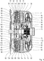
- Fig. 1 and 2 show a coupling arrangement 56 which has a housing 54 which can be rotated about a central axis 15 and, since it is designed as a hydrodynamic torque converter 90, has a hydrodynamic circuit 60 with pump wheel 61, turbine wheel 62 and stator 63. Furthermore, the coupling arrangement 56 is provided with a vibration reduction device 30 and with a coupling device 64, the vibration reduction device 30 having a torsional vibration damper 70 and a damper system 1.
- a housing section 55 for fastening an input 67 of the torsional vibration damper 70 is provided on a housing cover 124 of the housing 54 of the coupling arrangement 56.
- the input 67 engages in the cross-sectional area of a radially outer energy storage system 126 with control fingers 114 that run essentially parallel to one another and each extend in a direction pointing away from the housing cover 124, with two control fingers 114 each acting as control element 80.
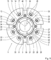
- the input 67 can be formed in one piece in the circumferential direction in that it surrounds the central axis 15 at a predetermined radial distance, or it can, like the Figures 3 and 4 can be recognized, be formed with a plurality of input segments 115 which surround the central axis 15 at a predetermined radial distance and with predetermined circumferential distances from one another.
- the attachment of the inlet 67 or the inlet segments 115 to the housing cover 124 takes place in a comparable manner, in that a base area 91 ( Figs. 2 to 4 ) is provided, which comes to rest on the housing cover 124, and with recesses 92 ( Fig. 3, 4 ) is provided by connecting devices 93 ( Fig. 1 ) are penetrated.
- connecting devices 93 are formed by rivets, which are displaced by means of plastic deformation from the outside of the housing cover 124 in the direction of the inlet 67 or the inlet segment 115, in order to achieve the respectively assigned To penetrate recess 92.
- the rivet is then completed with a deformation from the opposite direction.
- a riveted connection produced in this way is pressure-tight, which is necessary in the area of the housing cover 124.
- weld points set in the recesses 92 can also be used as connecting devices 93.
- the recesses 92 are, as far as the input segments 115 are concerned, either at their peripheral ends 106 ( Fig. 3 ), or in the circumferential area of extent of these ends 106 ( Fig. 4 ).
- the recesses 92 are designed as notches engaging the base area 91 from the outside on the circumference, while in the last-mentioned case, bores are provided which penetrate the base area 91.
- a guide area 79 provided on a guide 78 for the energy stores of the radially outer energy storage system 126 is provided.
- This guide 78 provides the energy stores of the radially outer energy storage system 126 with radial support when they are pressed outward by radial forces caused by centrifugal forces.
- the guide area 79 of this guide 78 is also in its radial outer area ( Fig. 1 , 2 ) formally adapted in the direction of its axial extent to the outer contour of the energy storage device of the radially outer energy storage system 126, so that this also enables the energy storage system 126 to be positioned in the axial direction.
- the housing 54 of the coupling arrangement 56 has in its radial outer area a wall 82 which, at least in the axial extent area of the greatest radial extent of the guide 78 and the radially outer energy storage system 126, has an indentation 83 into which the guide 78 dips along part of its axial extent.
- This structural configuration enables the energy stores of the radially outer energy storage system 126 to be displaced radially outward as far as possible.
- the guide 78 can be designed with a small material cross-section, in particular when made from spring material, which results in comparatively little wear with a low material cross-section requirement. The last-mentioned measure becomes possible if the guide 78 of the inlet 67 can be supported radially outward on the wall of the housing 54. This results in a further possibility of displacing the energy stores of the radially outer energy storage system 126 radially outward as far as possible.
- the measures for displacing the energy stores of the radially outer energy storage system 126 radially as far as possible outwards serve the aim of introducing the highest possible deformation volume into the radially outer energy storage system 126 while at the same time having a low rigidity of the energy storage system 126. In this way, a high quality of decoupling of the torsional vibration damper 70 and thus of the vibration reducing device 30 is achieved.
- Control elements 116 each grip radially between the two control fingers 114 of input 67 ( Fig. 1 ) an intermediate transmission 74, the control elements 116 of the intermediate transmission projecting into the cross-sectional area of extent of the radially outer energy storage system 126 in the direction pointing towards the housing cover 124.
- the intermediate transmission 74 runs, at least substantially, radially inward, in order to be in the radially inner region in energy storage windows 128 ( Fig. 2 ) Take up energy storage of a radially inner energy storage system 130.
- Output components 117, 118 are provided axially on both sides of the intermediate transmission 74 and have energy storage windows 132 for the energy storage of the radially inner energy storage system 130.
- the output components 117, 118 are supported by a bearing 108 arranged in the axial direction with several outer sections of different outer diameters and by spacers 134 ( Fig. 1 ) held at a predetermined axial distance from one another and to the intermediate transmission 74, the spacers 134 reaching through recesses in the intermediate transmission 74 with play in the circumferential direction.
- spacers 134 With a relative rotational deflection of the intermediate transmission 74 and output components 117, 118 have reached the ends of the recesses following in the deflection direction, the relative rotational deflection ends.
- the spacers 134 accordingly act as a relative rotation angle limiter 136.
- the input 67 together with the radially outer energy storage system 126 and the intermediate transmission 74, forms a drive-side first damping unit 68 of the torsional vibration damper 70
- the intermediate transmission 74 together with the radially inner energy storage system 130 and the output components 117, 118, forms a second damping unit 69 of the torsional vibration damper 70 on the output side .
- Both the intermediate transmission 74 and the output component 118 are each centered and axially positioned on the bearing 108 assigned to a torsional vibration damper hub 71, but can move in the circumferential direction both relative to the bearing 108 and relative to one another.
- the housing 54 of the coupling arrangement 56 acts as a drive 52, and the output components 117, 118 each act as an output 72.
- the output 72 is centered on the torsional vibration damper hub 71 acting as an output 73, which in turn is by means of a toothing (not shown) is added to an output shaft, such as a transmission input shaft.
- the torsional vibration damper hub 71 is supported axially on the housing cover 124 and centers a clutch piston 65 of the clutch device 64 so that it can be axially displaced.
- a component independent of the torsional vibration damper hub 71 can also be provided for centering the clutch piston 65, this component being supported and connected to the torsional vibration damper hub 71.
- the clutch piston 65 is non-rotatably attached to a receiving component 113 of the clutch device 64 by means of an axial suspension 142, which, like the turbine wheel 62, is attached to the torsional vibration damper hub 71 by means of riveting 122.
- the clutch piston 65 axially displaceable along the torsional vibration damper hub 71, its movement in the direction of the receiving component 113 being limited by an axial stop 140. If the clutch piston 65 moves in the direction of the receiving component 113, then it moves to its engagement position in a first operating state, while the clutch piston 65 moves to its disengaged position in a second operating state as a result of a movement in the opposite direction.
- the torsional vibration damper 70 takes on its output component 118 facing the turbine wheel 62 for a second function of this output component 118 a damper mass carrier element 5a of a damper mass carrier 3 of the damper system 1, which is axially fixed with a second damper mass carrier element 5b by means of spacers Distance is rotatably connected.
- the two absorber mass carrier elements 5a, 5b axially accommodate absorber masses 7 with a plurality of absorber mass elements 7a to 7c between them.
- the spacers 11 each serve in a second function to accommodate an annular component 32 ( Fig. 5 , 6th ).
- the output component 117 facing away from the turbine wheel 62 serves, also for a second function, as a friction disk clutch carrier 120, on which a friction disk clutch 66 engaging axially between the clutch piston 65 and the receiving component 113 is held in a rotationally fixed but axially displaceable manner. Since the output components 117, 118 are each part of the output 72, both the damper system 1 and the coupling device 64 are each connected to the output 72.
- first pressure medium is fed into the hydrodynamic circuit by means of a pressure source (not shown) via a first line 95 60 and thus also passed into a first pressure chamber 98 which extends axially between the housing cover 124 and the clutch piston 65. This creates an overpressure in the first pressure chamber 98 compared to the second pressure chamber 99, which is located on the opposite side of the clutch piston 65, that is between the same and the receiving component 113.
- the clutch piston 65 is thereby displaced in the direction of the receiving component 113, and in this case the friction disk clutch 66 clamps between itself and the receiving component 113 with increasing strength.
- pressure medium contained in the second pressure chamber 99 is discharged from the second pressure chamber 99 via a second line 96, which is pressureless in this operating state, and then reaches a pressure medium supply (not shown).
- the clutch piston 65 For a movement of the clutch piston 65 in its second operating state, the clutch piston 65 is moved in a direction pointing away from the receiving component 113 in order to cancel the connection between the drive 52 and the output 73 again.
- pressure medium is fed into the second pressure chamber 99 via the second line 96 by means of the pressure source, which is not shown, as a result of which an overpressure relative to the first pressure chamber 98 arises there.
- the clutch piston 65 is thereby displaced in a direction pointing away from the receiving component 113, and in the process releases the friction disk clutch 66 between itself and the receiving component 113 more and more.
- the axial spring 142 is either designed in such a way that it tries to keep the clutch piston 65 at a distance from the receiving component 113, or it is designed in such a way that it tries to press the clutch piston 65 in the direction of the receiving component 113.
- possible drag losses can be reduced, which can occur if the friction disc clutch 66 adheres to the clutch piston 65 or to the receiving component 113 when the clutch piston 65 is at least partially disengaged, while in the latter case a lower pressure gradient between the first pressure chamber 98 and the second pressure chamber 99 is sufficient, in order to hold the clutch device 64 in its first operating state in the engagement position.
- the axial spring 142 can counteract pressure changes, which can occur suddenly due to the flow. As a result, a less shock-absorbing engagement of the clutch device 64 is promoted.
- Torsional vibrations or excitations that are transmitted together with a torque applied to the housing 54 from the housing 54 via the input 67 to the torsional vibration damper 70 are on the one hand damped by the damping units 68, 69, and on the other hand are canceled by the damper system 1. Due to the direct connection of the damper system 1 via the torsional vibration damper 70 to the housing 54 and thus to the drive 52, it is ensured that the excitation applied to the damper system 1 is always at the same speed as the excitation applied to the drive 52. As a result, the damper system 1 can be designed precisely in accordance with the order linked to the drive 52.
- the torsional vibration damper 70 in which there is a connection between the output 72 and the damper system 1, has at least approximately one vibration node at the output 72, then there is the possibility of using a slip on the coupling device 64, with the result that a stronger Rotational nonuniformity is present at the coupling device 64 and thus at least at the output 72 of the torsional vibration damper 70, which is required for a sufficiently favorable decoupling performance of the damper system 1. Since the coupling device 64 is provided behind the damper system 1, the damper system 1 remains designed for the order linked to the drive 52 without being influenced by this measure.
- damper system 1 In favor of better representability of the absorber masses 7 recorded on the absorber mass carrier 3 is in the Fig. 5 and 6th in each case the absorber mass carrier element 5a arranged axially in front of the absorber masses 7 in the viewing direction is removed, and only the absorber mass carrier element 5b arranged axially behind the absorber masses 7 in the viewing direction is shown.
- the damper masses 7 each have guide tracks 22 designed in pairs for receiving coupling elements 20 each designed as rolling bodies, the guide tracks 22 being designed in such a way that that they enable a radial relative movement of the damper masses 7 with respect to the coupling elements 20.
- the damper masses 7 have stop sides 43, adjoining their peripheral sides 42 radially on the inside.
- guide tracks 13 are provided, which have a curved course. As shown in Fig. 5 or 6th the guideways 13 each have an exit area 14, in which the respective guideway 13 has the greatest radial distance from a central axis 15, and connecting areas 17, which extend circumferentially opposite to one another, connect to both sides of the exit area 14.
- the guide tracks 22 provided on the absorber masses 7 also have a curved course, each with an output area 24 in which the respective guide track 22 has the smallest radial distance from the central axis 15, and with connection areas 25 which extend circumferentially opposite to one another Connect both sides of the output area 24.
- the guide tracks 22 are each provided on both sides of a damper mass center 35 of the respective damper mass.
- This absorber mass center 35 is located in a mean extension radius 36 of the absorber mass 7, which is arranged at a distance R1 from the central axis 15 when the vehicle is in motion.
- the state of the damper masses 7 when driving is in Fig. 5 shown, and occurs when the damper system 1 is operated at a speed at which the centrifugal force exceeds the weight.
- the coupling elements 20 received in the guide tracks 13 and 22 each engage on both sides of the respective guide track 22 in the guide tracks 13 provided there.
- the damper masses 7 strive radially outwards, so that the coupling elements 20 are each positioned in the output area 24 of the respective guide track 22, i.e. in the area that has the smallest radial distance from the central axis 15.
- the coupling elements 20 are each supported in the output area 14 of the damper mass carrier elements 5a and 5b, that is to say in that area which has the greatest radial distance from the central axis 15.
- the damper masses 7 each have at their radially inner ends a geometric projection 28 which has a first contact area 26 in the circumferentially central part, but has second contact areas 27 in the circumferentially outer parts.
- the first contact area 26 has an area center 37, which divides the first contact area 29 into molded halves 23.
- This geometric projection 28 interacts in a manner still to be described below with stops 31 provided radially inside the damper masses 7, which are combined on an annular component 32.
- the ring-shaped component 32 In the circumferential direction between two damper masses 7, the ring-shaped component 32 has a respective holder 34, each of which encloses a spacer 11, so that the holder 34 serves as a stop sensor 38 in each case.
- the annular component 32 is accordingly received on the damper mass carrier 3 in a rotationally fixed manner.
- An annular body 33 extending in the circumferential direction acts between two stop sensors 38 each with a stop profile 40. Stop sensor 38 and stop profiles 40 together form stops 31 on the annular component 32.
- the damper masses 7 fall radially inward by the in Fig. 6 to assume the relative position shown to each other and to the absorber mass carrier 3. In such an operating state, the two fall radially Above the central axis 15 damper masses 7 located radially inward until their stop sides 43 come into contact with the associated stop profile 40 of the stop 31 on the ring body 33 of the ring-shaped component 32 with the molded half 23 of the first contact area 26 relevant for the direction of movement.
- the two damper masses 7 located radially below the central axis 15 also fall radially inward until their stop sides 43 with the first contact areas 26 formed thereon and relevant for the direction of movement come into contact with the assigned stop profile 40 of the stop 31 on the ring body 33 of the ring-shaped component 32 have come, and until the second contact areas 27 of the respective damper masses 7, which are relevant for the direction of movement, have come into contact with the corresponding brackets 34 and thus with the stop sensors 38 of the annular component 32. This prevents the two damper masses 7 located radially below the central axis 15 from coming into contact with one another with their peripheral sides 42.
Landscapes
- Engineering & Computer Science (AREA)
- General Engineering & Computer Science (AREA)
- Physics & Mathematics (AREA)
- Acoustics & Sound (AREA)
- Aviation & Aerospace Engineering (AREA)
- Mechanical Engineering (AREA)
- Mechanical Operated Clutches (AREA)
Claims (12)
- Dispositif de réduction de vibrations d'un ensemble d'accouplement (56), qui comprend un amortisseur de vibrations de torsion (70) doté d'une entrée (67) reliée à un entraînement (52), laquelle entrée sert, au moyen d'éléments de commande (80), à solliciter un système d'accumulation d'énergie (126) d'au moins une unité d'amortissement (68) de l'amortisseur de vibrations de torsion (70) dans la direction périphérique, et comprend, pour supporter le système d'accumulation d'énergie (126) de l'unité d'amortissement (68) radialement vers l'extérieur, un guide (78) qui coopère avec les éléments de commande (80) faisant saillie dans la région d'étendue du système d'accumulation d'énergie (126), afin de pouvoir solliciter le système d'accumulation d'énergie (126) dans la direction périphérique, l'entrée (67) de l'amortisseur de vibrations de torsion comportant à la fois le guide (78) et les éléments de commande (80) pour le système d'accumulation d'énergie (126) de l'unité d'amortissement (68), l'entrée (67) de l'amortisseur de vibrations de torsion (70) étant fixée à l'entraînement (57), et le guide (78) entourant le système d'accumulation d'énergie (126) au moins le long d'une partie de l'étendue axiale respective par une région de guidage (79) adaptée par sa forme au contour extérieur du système d'accumulation d'énergie (126), le dispositif de réduction de vibrations, logé dans un boîtier (54), comprenant une paroi (82) dans la région extérieure radiale, la fixation de l'entrée (67) de l'amortisseur de vibrations de torsion (70) à une partie (55) du boîtier (54) ayant lieu, laquelle partie de boîtier est prévue à une distance de la paroi (82) dans la région extérieure radiale du boîtier (54), cette distance étant sélectionnée de telle sorte que le guide (78) subit un support radialement vers l'extérieur au moyen de la paroi (82) présente dans la région extérieure radiale du boîtier (54),
caractérisé en ce que la paroi (82) comporte, dans la région extérieure radiale du boîtier (54), pour le support du guide (78) radialement vers l'extérieur, un renfoncement (83) dans lequel le guide (78) pénètre au moins le long d'une partie de son étendue axiale. - Dispositif un de réduction de vibrations selon la revendication 1, caractérisé en ce que l'entrée (67) de l'amortisseur de vibrations de torsion (70) comprend une région de base (91) prévue pour la fixation au boîtier (54), région à partir de laquelle à la fois la région de guidage (79) du guide (78) et les éléments de commande (80) s'étendent en direction du système d'accumulation d'énergie (126) de l'unité d'amortissement (68).
- Dispositif de réduction de vibrations selon la revendication 2, caractérisé en ce que la région de base (91) de l'entrée (67) de l'amortisseur de vibrations de torsion (70) comporte des évidements (92) qui sont prévus pour le logement respectivement d'un dispositif de liaison (93) réalisant la fixation au boîtier (54).
- Dispositif de réduction de vibrations selon les revendications 1 et 3, caractérisé en ce que l'entrée (67) de l'amortisseur de vibrations de torsion (70) comporte une pluralité de segments d'entrée (115) présentant une étendue limitée dans la direction périphérique, segments dans lesquels les évidements (92) pour le dispositif de liaison (93) respectif et/ou les éléments de commande (80) se trouvent respectivement aux extrémités (106) côté périphérie ou au moins dans la région d'étendue côté périphérie de ces extrémités (106).
- Dispositif de réduction de vibrations selon la revendication 1, dont la sortie (72) est reliée à un dispositif d'embrayage (64) au moyen duquel, dans un premier état de fonctionnement, une liaison entre l'entraînement (52) et une prise de force (73) est produite au moins sensiblement et, dans un deuxième état de fonctionnement, cette liaison est au moins sensiblement supprimée, caractérisé en ce qu'un système d'amortissement (1) coopérant avec l'amortisseur de vibrations de torsion (70) est prévu, lequel système d'amortissement est relié à la sortie (72) de l'amortisseur de vibrations de torsion (70).
- Dispositif de réduction de vibrations selon la revendication 5, doté d'un amortisseur de vibrations de torsion (70) logé de manière centrée mais rotative relativement dans la direction périphérique, caractérisé en ce que le centrage de l'amortisseur de vibrations de torsion (70) au niveau de la prise de force (73) s'effectue au moyen d'un palier (108).
- Dispositif de réduction de vibrations selon la revendication 5, dans lequel l'amortisseur de vibrations de torsion (70) est relié à au moins un embrayage à disques de friction (66 ; 84, 85) du dispositif d'embrayage (64) qui, dans le premier état de fonctionnement, sous l'effet d'un piston d'embrayage (65) associé au dispositif d'embrayage (64), est pressé contre un composant de logement (113) solidaire en rotation avec la prise de force (73), tandis que le piston d'embrayage (65), dans le deuxième état de fonctionnement, en faveur d'une suppression au moins partielle de la liaison fonctionnelle entre l'au moins un embrayage à disques de friction (66 ; 84, 85) et le composant de logement (113), libère l'au moins un embrayage à disques de friction (66 ; 84, 85) au moins sensiblement.
- Dispositif de réduction de vibrations selon la revendication 5, dans lequel l'amortisseur de vibrations de torsion (70) comprend au moins une unité d'amortissement (69) dont la sortie (72) comporte au moins deux composants de sortie (117, 118), parmi lesquels au moins un composant de sortie (117, 118) est logé de manière centrée, mais mobile en rotation dans la direction périphérique, caractérisé en ce qu'au moins un composant de sortie (118) comprend une liaison avec un support de masse d'amortissement (3), prévu pour le logement de masses d'amortissement (7), du système d'amortissement (1).
- Dispositif de réduction de vibrations selon la revendication 8, caractérisé en ce qu'au moins un composant de sortie (117) de la sortie (72) est prévu en tant que support d'embrayage à disques de friction (120 ; 88) du dispositif d'embrayage (64), lequel loge l'au moins un embrayage à disques de friction (66 ; 84, 85) du dispositif d'embrayage (64) de manière bloquée en rotation.
- Dispositif de réduction de vibrations selon la revendication 8, comportant un amortisseur de vibrations de torsion (70) qui comprend une pluralité d'unités d'amortissement (68, 69), parmi lesquelles l'unité d'amortissement (68) respectivement côté entraînement est en liaison fonctionnelle avec l'unité d'amortissement (69) respectivement côté prise de force par le biais d'une transmission intermédiaire (74), caractérisé en ce que la transmission intermédiaire (74) agit comme entrée pour l'unité d'amortissement (69) côté prise de force.
- Dispositif de réduction de vibrations selon la revendication 8, caractérisé en ce que le système d'amortissement (1) comporte un support d'embrayage à disques de friction (88), lequel loge de manière bloquée en rotation l'au moins un embrayage à disques de friction (84, 85) du dispositif d'embrayage (64).
- Ensemble d'accouplement comportant un dispositif de réduction de vibrations selon la revendication 1, dont la sortie (72) est reliée à un dispositif d'embrayage (64) au moyen duquel, dans un premier état de fonctionnement, une liaison entre l'entraînement (52) et une prise de force (73) est produite au moins sensiblement et, dans un deuxième état de fonctionnement, cette liaison est au moins sensiblement supprimée, caractérisé en ce que le dispositif de réduction de vibrations (30) comprend un système d'amortissement (1) coopérant avec l'amortisseur de vibrations de torsion (70), lequel système d'amortissement est relié à une transmission intermédiaire (74), laquelle est reliée entre une première unité d'amortissement (68) côté entraînement et une deuxième unité d'amortissement (69), côté prise de force, de l'amortisseur de vibrations de torsion (70) du dispositif de réduction de vibrations (30).
Applications Claiming Priority (2)
| Application Number | Priority Date | Filing Date | Title |
|---|---|---|---|
| DE102014220899.8A DE102014220899A1 (de) | 2014-10-15 | 2014-10-15 | Schwingungsreduzierungseinrichtung |
| PCT/EP2015/070996 WO2016058763A1 (fr) | 2014-10-15 | 2015-09-15 | Dispositif de réduction de vibrations |
Publications (2)
| Publication Number | Publication Date |
|---|---|
| EP3207276A1 EP3207276A1 (fr) | 2017-08-23 |
| EP3207276B1 true EP3207276B1 (fr) | 2021-12-22 |
Family
ID=54106367
Family Applications (1)
| Application Number | Title | Priority Date | Filing Date |
|---|---|---|---|
| EP15763329.8A Not-in-force EP3207276B1 (fr) | 2014-10-15 | 2015-09-15 | Dispositif de réduction de vibrations |
Country Status (3)
| Country | Link |
|---|---|
| EP (1) | EP3207276B1 (fr) |
| DE (1) | DE102014220899A1 (fr) |
| WO (1) | WO2016058763A1 (fr) |
Family Cites Families (8)
| Publication number | Priority date | Publication date | Assignee | Title |
|---|---|---|---|---|
| DE19831158A1 (de) * | 1998-07-11 | 2000-01-13 | Freudenberg Carl Fa | Schwungrad |
| JP4935006B2 (ja) | 2005-07-06 | 2012-05-23 | アイシン・エィ・ダブリュ株式会社 | 流体伝動装置 |
| JP2009500581A (ja) * | 2005-07-14 | 2009-01-08 | ルーク ラメレン ウント クツプルングスバウ ベタイリグングス コマンディートゲゼルシャフト | 振動減衰装置、特にデュアルマスフライホイール |
| JP2009243599A (ja) * | 2008-03-31 | 2009-10-22 | Aisin Aw Co Ltd | ダンパ装置 |
| DE102009042811A1 (de) * | 2008-10-27 | 2010-04-29 | Luk Lamellen Und Kupplungsbau Beteiligungs Kg | Vorrichtung zur Dämpfung von Schwingungen |
| DE102011076790B4 (de) | 2011-05-31 | 2023-07-13 | Zf Friedrichshafen Ag | Antriebssystem für ein Fahrzeug |
| EP2600030A3 (fr) * | 2011-12-01 | 2018-01-03 | Schaeffler Technologies AG & Co. KG | Convertisseur de couple |
| DE102013205919A1 (de) * | 2013-04-04 | 2014-10-09 | Schaeffler Technologies Gmbh & Co. Kg | Drehschwingungsdämpfer |
-
2014
- 2014-10-15 DE DE102014220899.8A patent/DE102014220899A1/de not_active Ceased
-
2015
- 2015-09-15 EP EP15763329.8A patent/EP3207276B1/fr not_active Not-in-force
- 2015-09-15 WO PCT/EP2015/070996 patent/WO2016058763A1/fr not_active Ceased
Also Published As
| Publication number | Publication date |
|---|---|
| DE102014220899A1 (de) | 2016-04-21 |
| EP3207276A1 (fr) | 2017-08-23 |
| WO2016058763A1 (fr) | 2016-04-21 |
Similar Documents
| Publication | Publication Date | Title |
|---|---|---|
| WO2016058762A1 (fr) | Dispositif d'accouplement avec ensemble de réduction de vibrations et ensemble d'accouplement | |
| DE102011017659A1 (de) | Drehmomentübertragungsbaugruppe, insbesondere für den Antriebsstrang eines Fahrzeuges | |
| EP2875259B1 (fr) | Amortisseur d'oscillations et dispositif d'amortissement | |
| DE102006028556A1 (de) | Drehmomentübertragungseinrichtung | |
| WO2012095072A1 (fr) | Dispositif pendulaire à force centrifuge | |
| WO2014012736A1 (fr) | Dispositif d'amortissement | |
| DE102011017660A1 (de) | Drehmomentübertragungsanordnung | |
| EP2872797B1 (fr) | Amortisseur de vibrations torsionnelles | |
| EP1943437B1 (fr) | Combinaison d'un amortisseur de vibrations de torsion et d'un villebrequin | |
| EP2853773B1 (fr) | Amortisseur d'oscillations de torsion | |
| DE3721710C2 (de) | Einrichtung zum Dämpfen von Schwingungen | |
| DE10338673B4 (de) | Kupplungsvorrichtung | |
| DE102004044362B4 (de) | Kupplungsscheibenanordnung | |
| WO2017028858A1 (fr) | Pendule à force centrifuge et convertisseur de couple hydrodynamique équipé d'un pendule à force centrifuge | |
| DE102012216116B4 (de) | Riemenscheibenentkoppler | |
| EP2853772A1 (fr) | Amortisseur d'oscillations de torsion | |
| DE19726532A1 (de) | Torsionsschwingungsdämpfer mit Wälzkörpern als Koppelelemente | |
| WO2007054047A2 (fr) | Embrayage a disques et dispositif convertisseur de couple hydrodynamique equipe d'un tel embrayage a disques | |
| WO2015165669A1 (fr) | Atténuateur d'oscillations à amortissement et procédé de production d'un atténuateur d'oscillations à amortissement | |
| EP3580471B1 (fr) | Arrangement de transmission de couple | |
| EP2994665A1 (fr) | Dispositif de transmission de couple | |
| EP1726847B1 (fr) | Combinaison d'un ammortisseur de torsion avec un embrayage | |
| DE102014220901A1 (de) | Baueinheit einer Kopplungsanordnung mit einer Schwingungsreduzierungseinrichtung und mit einer Kupplungseinrichtung | |
| EP1729025B1 (fr) | Dispositif d'embrayage multiple | |
| EP2853771B1 (fr) | Amortisseur d'oscillations de torsion |
Legal Events
| Date | Code | Title | Description |
|---|---|---|---|
| STAA | Information on the status of an ep patent application or granted ep patent |
Free format text: STATUS: THE INTERNATIONAL PUBLICATION HAS BEEN MADE |
|
| PUAI | Public reference made under article 153(3) epc to a published international application that has entered the european phase |
Free format text: ORIGINAL CODE: 0009012 |
|
| STAA | Information on the status of an ep patent application or granted ep patent |
Free format text: STATUS: REQUEST FOR EXAMINATION WAS MADE |
|
| 17P | Request for examination filed |
Effective date: 20170314 |
|
| AK | Designated contracting states |
Kind code of ref document: A1 Designated state(s): AL AT BE BG CH CY CZ DE DK EE ES FI FR GB GR HR HU IE IS IT LI LT LU LV MC MK MT NL NO PL PT RO RS SE SI SK SM TR |
|
| AX | Request for extension of the european patent |
Extension state: BA ME |
|
| DAV | Request for validation of the european patent (deleted) | ||
| DAX | Request for extension of the european patent (deleted) | ||
| GRAP | Despatch of communication of intention to grant a patent |
Free format text: ORIGINAL CODE: EPIDOSNIGR1 |
|
| STAA | Information on the status of an ep patent application or granted ep patent |
Free format text: STATUS: GRANT OF PATENT IS INTENDED |
|
| INTG | Intention to grant announced |
Effective date: 20210907 |
|
| GRAS | Grant fee paid |
Free format text: ORIGINAL CODE: EPIDOSNIGR3 |
|
| GRAA | (expected) grant |
Free format text: ORIGINAL CODE: 0009210 |
|
| STAA | Information on the status of an ep patent application or granted ep patent |
Free format text: STATUS: THE PATENT HAS BEEN GRANTED |
|
| AK | Designated contracting states |
Kind code of ref document: B1 Designated state(s): AL AT BE BG CH CY CZ DE DK EE ES FI FR GB GR HR HU IE IS IT LI LT LU LV MC MK MT NL NO PL PT RO RS SE SI SK SM TR |
|
| REG | Reference to a national code |
Ref country code: GB Ref legal event code: FG4D Free format text: NOT ENGLISH |
|
| REG | Reference to a national code |
Ref country code: CH Ref legal event code: EP |
|
| REG | Reference to a national code |
Ref country code: DE Ref legal event code: R096 Ref document number: 502015015517 Country of ref document: DE |
|
| REG | Reference to a national code |
Ref country code: AT Ref legal event code: REF Ref document number: 1457271 Country of ref document: AT Kind code of ref document: T Effective date: 20220115 |
|
| REG | Reference to a national code |
Ref country code: IE Ref legal event code: FG4D Free format text: LANGUAGE OF EP DOCUMENT: GERMAN |
|
| REG | Reference to a national code |
Ref country code: LT Ref legal event code: MG9D |
|
| PG25 | Lapsed in a contracting state [announced via postgrant information from national office to epo] |
Ref country code: RS Free format text: LAPSE BECAUSE OF FAILURE TO SUBMIT A TRANSLATION OF THE DESCRIPTION OR TO PAY THE FEE WITHIN THE PRESCRIBED TIME-LIMIT Effective date: 20211222 Ref country code: LT Free format text: LAPSE BECAUSE OF FAILURE TO SUBMIT A TRANSLATION OF THE DESCRIPTION OR TO PAY THE FEE WITHIN THE PRESCRIBED TIME-LIMIT Effective date: 20211222 Ref country code: FI Free format text: LAPSE BECAUSE OF FAILURE TO SUBMIT A TRANSLATION OF THE DESCRIPTION OR TO PAY THE FEE WITHIN THE PRESCRIBED TIME-LIMIT Effective date: 20211222 Ref country code: BG Free format text: LAPSE BECAUSE OF FAILURE TO SUBMIT A TRANSLATION OF THE DESCRIPTION OR TO PAY THE FEE WITHIN THE PRESCRIBED TIME-LIMIT Effective date: 20220322 |
|
| REG | Reference to a national code |
Ref country code: NL Ref legal event code: MP Effective date: 20211222 |
|
| PG25 | Lapsed in a contracting state [announced via postgrant information from national office to epo] |
Ref country code: SE Free format text: LAPSE BECAUSE OF FAILURE TO SUBMIT A TRANSLATION OF THE DESCRIPTION OR TO PAY THE FEE WITHIN THE PRESCRIBED TIME-LIMIT Effective date: 20211222 Ref country code: NO Free format text: LAPSE BECAUSE OF FAILURE TO SUBMIT A TRANSLATION OF THE DESCRIPTION OR TO PAY THE FEE WITHIN THE PRESCRIBED TIME-LIMIT Effective date: 20220322 Ref country code: LV Free format text: LAPSE BECAUSE OF FAILURE TO SUBMIT A TRANSLATION OF THE DESCRIPTION OR TO PAY THE FEE WITHIN THE PRESCRIBED TIME-LIMIT Effective date: 20211222 Ref country code: HR Free format text: LAPSE BECAUSE OF FAILURE TO SUBMIT A TRANSLATION OF THE DESCRIPTION OR TO PAY THE FEE WITHIN THE PRESCRIBED TIME-LIMIT Effective date: 20211222 Ref country code: GR Free format text: LAPSE BECAUSE OF FAILURE TO SUBMIT A TRANSLATION OF THE DESCRIPTION OR TO PAY THE FEE WITHIN THE PRESCRIBED TIME-LIMIT Effective date: 20220323 |
|
| PG25 | Lapsed in a contracting state [announced via postgrant information from national office to epo] |
Ref country code: NL Free format text: LAPSE BECAUSE OF FAILURE TO SUBMIT A TRANSLATION OF THE DESCRIPTION OR TO PAY THE FEE WITHIN THE PRESCRIBED TIME-LIMIT Effective date: 20211222 |
|
| PG25 | Lapsed in a contracting state [announced via postgrant information from national office to epo] |
Ref country code: SM Free format text: LAPSE BECAUSE OF FAILURE TO SUBMIT A TRANSLATION OF THE DESCRIPTION OR TO PAY THE FEE WITHIN THE PRESCRIBED TIME-LIMIT Effective date: 20211222 Ref country code: SK Free format text: LAPSE BECAUSE OF FAILURE TO SUBMIT A TRANSLATION OF THE DESCRIPTION OR TO PAY THE FEE WITHIN THE PRESCRIBED TIME-LIMIT Effective date: 20211222 Ref country code: RO Free format text: LAPSE BECAUSE OF FAILURE TO SUBMIT A TRANSLATION OF THE DESCRIPTION OR TO PAY THE FEE WITHIN THE PRESCRIBED TIME-LIMIT Effective date: 20211222 Ref country code: PT Free format text: LAPSE BECAUSE OF FAILURE TO SUBMIT A TRANSLATION OF THE DESCRIPTION OR TO PAY THE FEE WITHIN THE PRESCRIBED TIME-LIMIT Effective date: 20220422 Ref country code: ES Free format text: LAPSE BECAUSE OF FAILURE TO SUBMIT A TRANSLATION OF THE DESCRIPTION OR TO PAY THE FEE WITHIN THE PRESCRIBED TIME-LIMIT Effective date: 20211222 Ref country code: EE Free format text: LAPSE BECAUSE OF FAILURE TO SUBMIT A TRANSLATION OF THE DESCRIPTION OR TO PAY THE FEE WITHIN THE PRESCRIBED TIME-LIMIT Effective date: 20211222 Ref country code: CZ Free format text: LAPSE BECAUSE OF FAILURE TO SUBMIT A TRANSLATION OF THE DESCRIPTION OR TO PAY THE FEE WITHIN THE PRESCRIBED TIME-LIMIT Effective date: 20211222 |
|
| PG25 | Lapsed in a contracting state [announced via postgrant information from national office to epo] |
Ref country code: PL Free format text: LAPSE BECAUSE OF FAILURE TO SUBMIT A TRANSLATION OF THE DESCRIPTION OR TO PAY THE FEE WITHIN THE PRESCRIBED TIME-LIMIT Effective date: 20211222 |
|
| REG | Reference to a national code |
Ref country code: DE Ref legal event code: R097 Ref document number: 502015015517 Country of ref document: DE |
|
| PG25 | Lapsed in a contracting state [announced via postgrant information from national office to epo] |
Ref country code: IS Free format text: LAPSE BECAUSE OF FAILURE TO SUBMIT A TRANSLATION OF THE DESCRIPTION OR TO PAY THE FEE WITHIN THE PRESCRIBED TIME-LIMIT Effective date: 20220422 |
|
| PLBE | No opposition filed within time limit |
Free format text: ORIGINAL CODE: 0009261 |
|
| STAA | Information on the status of an ep patent application or granted ep patent |
Free format text: STATUS: NO OPPOSITION FILED WITHIN TIME LIMIT |
|
| PG25 | Lapsed in a contracting state [announced via postgrant information from national office to epo] |
Ref country code: DK Free format text: LAPSE BECAUSE OF FAILURE TO SUBMIT A TRANSLATION OF THE DESCRIPTION OR TO PAY THE FEE WITHIN THE PRESCRIBED TIME-LIMIT Effective date: 20211222 Ref country code: AL Free format text: LAPSE BECAUSE OF FAILURE TO SUBMIT A TRANSLATION OF THE DESCRIPTION OR TO PAY THE FEE WITHIN THE PRESCRIBED TIME-LIMIT Effective date: 20211222 |
|
| 26N | No opposition filed |
Effective date: 20220923 |
|
| PG25 | Lapsed in a contracting state [announced via postgrant information from national office to epo] |
Ref country code: SI Free format text: LAPSE BECAUSE OF FAILURE TO SUBMIT A TRANSLATION OF THE DESCRIPTION OR TO PAY THE FEE WITHIN THE PRESCRIBED TIME-LIMIT Effective date: 20211222 |
|
| PG25 | Lapsed in a contracting state [announced via postgrant information from national office to epo] |
Ref country code: MC Free format text: LAPSE BECAUSE OF FAILURE TO SUBMIT A TRANSLATION OF THE DESCRIPTION OR TO PAY THE FEE WITHIN THE PRESCRIBED TIME-LIMIT Effective date: 20211222 |
|
| REG | Reference to a national code |
Ref country code: CH Ref legal event code: PL |
|
| GBPC | Gb: european patent ceased through non-payment of renewal fee |
Effective date: 20220915 |
|
| REG | Reference to a national code |
Ref country code: BE Ref legal event code: MM Effective date: 20220930 |
|
| PG25 | Lapsed in a contracting state [announced via postgrant information from national office to epo] |
Ref country code: IT Free format text: LAPSE BECAUSE OF FAILURE TO SUBMIT A TRANSLATION OF THE DESCRIPTION OR TO PAY THE FEE WITHIN THE PRESCRIBED TIME-LIMIT Effective date: 20211222 |
|
| PG25 | Lapsed in a contracting state [announced via postgrant information from national office to epo] |
Ref country code: LU Free format text: LAPSE BECAUSE OF NON-PAYMENT OF DUE FEES Effective date: 20220915 |
|
| P01 | Opt-out of the competence of the unified patent court (upc) registered |
Effective date: 20230528 |
|
| PG25 | Lapsed in a contracting state [announced via postgrant information from national office to epo] |
Ref country code: LI Free format text: LAPSE BECAUSE OF NON-PAYMENT OF DUE FEES Effective date: 20220930 Ref country code: IE Free format text: LAPSE BECAUSE OF NON-PAYMENT OF DUE FEES Effective date: 20220915 Ref country code: FR Free format text: LAPSE BECAUSE OF NON-PAYMENT OF DUE FEES Effective date: 20220930 Ref country code: CH Free format text: LAPSE BECAUSE OF NON-PAYMENT OF DUE FEES Effective date: 20220930 |
|
| PG25 | Lapsed in a contracting state [announced via postgrant information from national office to epo] |
Ref country code: BE Free format text: LAPSE BECAUSE OF NON-PAYMENT OF DUE FEES Effective date: 20220930 |
|
| PG25 | Lapsed in a contracting state [announced via postgrant information from national office to epo] |
Ref country code: GB Free format text: LAPSE BECAUSE OF NON-PAYMENT OF DUE FEES Effective date: 20220915 |
|
| REG | Reference to a national code |
Ref country code: AT Ref legal event code: MM01 Ref document number: 1457271 Country of ref document: AT Kind code of ref document: T Effective date: 20220915 |
|
| PGFP | Annual fee paid to national office [announced via postgrant information from national office to epo] |
Ref country code: DE Payment date: 20230718 Year of fee payment: 9 |
|
| PG25 | Lapsed in a contracting state [announced via postgrant information from national office to epo] |
Ref country code: AT Free format text: LAPSE BECAUSE OF NON-PAYMENT OF DUE FEES Effective date: 20220915 |
|
| PG25 | Lapsed in a contracting state [announced via postgrant information from national office to epo] |
Ref country code: HU Free format text: LAPSE BECAUSE OF FAILURE TO SUBMIT A TRANSLATION OF THE DESCRIPTION OR TO PAY THE FEE WITHIN THE PRESCRIBED TIME-LIMIT; INVALID AB INITIO Effective date: 20150915 |
|
| PG25 | Lapsed in a contracting state [announced via postgrant information from national office to epo] |
Ref country code: CY Free format text: LAPSE BECAUSE OF FAILURE TO SUBMIT A TRANSLATION OF THE DESCRIPTION OR TO PAY THE FEE WITHIN THE PRESCRIBED TIME-LIMIT Effective date: 20211222 |
|
| PG25 | Lapsed in a contracting state [announced via postgrant information from national office to epo] |
Ref country code: MK Free format text: LAPSE BECAUSE OF FAILURE TO SUBMIT A TRANSLATION OF THE DESCRIPTION OR TO PAY THE FEE WITHIN THE PRESCRIBED TIME-LIMIT Effective date: 20211222 |
|
| PG25 | Lapsed in a contracting state [announced via postgrant information from national office to epo] |
Ref country code: TR Free format text: LAPSE BECAUSE OF FAILURE TO SUBMIT A TRANSLATION OF THE DESCRIPTION OR TO PAY THE FEE WITHIN THE PRESCRIBED TIME-LIMIT Effective date: 20211222 |
|
| PG25 | Lapsed in a contracting state [announced via postgrant information from national office to epo] |
Ref country code: MT Free format text: LAPSE BECAUSE OF FAILURE TO SUBMIT A TRANSLATION OF THE DESCRIPTION OR TO PAY THE FEE WITHIN THE PRESCRIBED TIME-LIMIT Effective date: 20211222 |
|
| REG | Reference to a national code |
Ref country code: DE Ref legal event code: R119 Ref document number: 502015015517 Country of ref document: DE |
|
| PG25 | Lapsed in a contracting state [announced via postgrant information from national office to epo] |
Ref country code: DE Free format text: LAPSE BECAUSE OF NON-PAYMENT OF DUE FEES Effective date: 20250401 |