EP3207587B1 - Elektrisch abstimmbare wellenleiterstruktur - Google Patents
Elektrisch abstimmbare wellenleiterstruktur Download PDFInfo
- Publication number
- EP3207587B1 EP3207587B1 EP14784090.4A EP14784090A EP3207587B1 EP 3207587 B1 EP3207587 B1 EP 3207587B1 EP 14784090 A EP14784090 A EP 14784090A EP 3207587 B1 EP3207587 B1 EP 3207587B1
- Authority
- EP
- European Patent Office
- Prior art keywords
- wall
- waveguide structure
- electrically conducting
- tuneable
- tuneable waveguide
- Prior art date
- Legal status (The legal status is an assumption and is not a legal conclusion. Google has not performed a legal analysis and makes no representation as to the accuracy of the status listed.)
- Active
Links
Images



Classifications
-
- H—ELECTRICITY
- H01—ELECTRIC ELEMENTS
- H01P—WAVEGUIDES; RESONATORS, LINES, OR OTHER DEVICES OF THE WAVEGUIDE TYPE
- H01P3/00—Waveguides; Transmission lines of the waveguide type
- H01P3/12—Hollow waveguides
-
- H—ELECTRICITY
- H01—ELECTRIC ELEMENTS
- H01P—WAVEGUIDES; RESONATORS, LINES, OR OTHER DEVICES OF THE WAVEGUIDE TYPE
- H01P1/00—Auxiliary devices
- H01P1/20—Frequency-selective devices, e.g. filters
- H01P1/201—Filters for transverse electromagnetic waves
- H01P1/2016—Slot line filters; Fin line filters
-
- H—ELECTRICITY
- H01—ELECTRIC ELEMENTS
- H01P—WAVEGUIDES; RESONATORS, LINES, OR OTHER DEVICES OF THE WAVEGUIDE TYPE
- H01P1/00—Auxiliary devices
- H01P1/20—Frequency-selective devices, e.g. filters
- H01P1/207—Hollow waveguide filters
-
- H—ELECTRICITY
- H02—GENERATION; CONVERSION OR DISTRIBUTION OF ELECTRIC POWER
- H02K—DYNAMO-ELECTRIC MACHINES
- H02K7/00—Arrangements for handling mechanical energy structurally associated with dynamo-electric machines, e.g. structural association with mechanical driving motors or auxiliary dynamo-electric machines
- H02K7/06—Means for converting reciprocating motion into rotary motion or vice versa
Definitions
- the present invention relates to a tuneable waveguide structure having a longitudinal extension and comprising a first inner wall, a second inner wall, a third inner wall and a fourth inner wall.
- the inner walls are constituted by respective main surfaces and are electrically conducting, where the first inner wall and the second inner wall are facing each other, and where the third inner wall and the fourth inner wall are facing each other.
- the intended extension of the electrical field is parallel to the main surfaces of the first inner wall and the second inner wall, and the intended extension of the electrical field is perpendicular to the main surfaces of the third inner wall and the fourth inner wall.
- the tuneable waveguide structure comprises at least one tuning device, where each tuning device comprises a wall part. Each wall part comprises one of the first inner wall and the second inner wall and is movably arranged along an extension that is perpendicular to the intended extension of the electrical field.
- microwave filters In wireless microwave links, radios are equipped with microwave filters, a typical example of such a filter is a diplexer between antenna, transmitter and receiver. These filters have to be adjusted to different frequencies within a band; this is today made in the assembly factory or by subcontractors. It would be desirable to allow a customer to set the frequency after the equipment is installed, and also to have the opportunity to change the frequency during the life of the product.
- E-plane filters for radio communication is a well-known technology.
- pin diodes, varactor diodes or ferroelectrics can be used to set the correct frequency.
- the usual way to implement electrical tuning devices in a waveguide is to vary the capacitive and inductive coupling in the waveguide and also to design additional structures in the waveguide to concentrate the electric field to the position where the tuning device is placed such as insertion of dielectric materials.
- WO 2012/016584 One way to obtain tuning of waveguide E-plane filters is described in WO 2012/016584 , where at least one row of switches is used for creating a virtual wall that is possible to turn on and turn off.
- Such switches may for example be realized by means of MEMS (Micro Electro Mechanical Systems).
- MEMS Micro Electro Mechanical Systems
- Such an arrangement provides a far better Q-factor than previous arrangemnts, but there is still a desire to obtain a less expensive tuneable waveguide E-plane filter with even better Q-factor.
- US-5808528-A shows an inductive strip waveguide band-pass filter includes a conductive movable wall which can be set to various positions to allow a varying "A" dimension, thereby setting controllably the center frequency of the filter over a predetermined range.
- the position of the movable wall can be set manually or by a motorized control mechanism. This document forms the preamble of claim 1.
- EP-1885018-A1 shows a tunable bandpass filter, comprising a plurality of resonator cavities being equipped with a movable frequency tuning elements extending at least partially in the cavity, and having a movable control element, wherein the frequency tuning elements and the control element are arranged such that an adjusting movement of the movable control element causes the tuning elements to be simultaneously displaced inside the waveguide in order to adjust the center frequencies of the resonator cavities.
- Each frequency tuning (10) element comprises a cam follower (12) which is projecting from a wall of the respective resonator cavity (2) to the outside and which is guided for shifting movement therein to allow to adjust the position of frequency tuning element (10) by sliding the cam follower (12) further inside or outside with respect to the resonator cavity wall.
- Each frequency tuning element is engaging with only one sloped cam surface of the movable control element. No movable wall part is provided.
- the object of the present invention is to provide an enhanced waveguide tuning device that is as well as an enhanced electrically tuneable waveguide structure, where the enhancement mainly relates to the Q-factor, the accuracy, easy maneuvering and manufacturing costs.
- the tuneable waveguide structure has a longitudinal extension and comprising a first inner wall, a second inner wall, a third inner wall and a fourth inner wall.
- the inner walls are constituted by respective main surfaces and are electrically conducting, where the first inner wall and the second inner wall are facing each other, and where the third inner wall and the fourth inner wall are facing each other.
- the intended extension of the electrical field is parallel to the main surfaces of the first inner wall and the second inner wall, and the intended extension of the electrical field is perpendicular to the main surfaces of the third inner wall and the fourth inner wall.
- the tuneable waveguide structure comprises at least one tuning device, where each tuning device comprises a wall part. Each wall part comprises one of the first inner wall and the second inner wall and is movably arranged along an extension that is perpendicular to the intended extension of the electrical field.
- each tuning device comprises an adjustment arrangement that in turn comprises at least two support rods that at least indirectly are connected to the corresponding wall part.
- the adjustment arrangement further comprises a sloped surface for each support rod, where each sloped surface is in sliding engagement with a corresponding support rod and is laterally adjustable in the extension of the slope.
- each tuning device comprises a support part that is arranged to support the wall part, where the wall part is in the form of an electrically conducting foil that is in electrical contact with the third inner wall and the fourth inner wall.
- the support part is connected to the adjustment arrangement that is arranged to displace the support part along an extension that is perpendicular to the intended extension of the electrical field.
- the support part comprises moveable parts and intermediate parts which are positioned between and beside the moveable parts.
- Each moveable part is connected to a corresponding support rod, where at least one sloped surface is arranged with a slope rate that differs from the other.
- each sloped surface is comprised in corresponding slope block and is connected to a slide bar that in turn is connected to a screw drive arrangement, where a rotational movement of at least a part of the screw drive arrangement) is arranged to displace the slide bar.
- the screw drive arrangement comprises an electrical motor that is arranged to run a screw gear that in turn is arranged to displace the slide bar.
- the electrically conducting foil is attached to the third inner wall and the fourth inner wall.
- the electrically conducting foil may comprise contact fingers that are resiliently electrically contacting the third inner wall and the fourth inner wall.
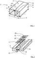
- FIG. 1 showing a schematic perspective view of an E-plane filter, there is a tuneable waveguide structure 2 in the form of an E-plane filter having a longitudinal extension L and comprising a fist inner wall 3, a second inner wall 4, a third inner wall 5 and a fourth inner wall 6.
- a tuneable waveguide structure 2 in the form of an E-plane filter having a longitudinal extension L and comprising a fist inner wall 3, a second inner wall 4, a third inner wall 5 and a fourth inner wall 6.
- a tuneable waveguide structure 2 in the form of an E-plane filter having a longitudinal extension L and comprising a fist inner wall 3, a second inner wall 4, a third inner wall 5 and a fourth inner wall 6.
- the inner walls are indicated in Figure 1 .
- the inner walls 3, 4, 5, 6 are constituted by respective main surfaces and are electrically conducting, the inner walls 3, 4, 5, 6 furthermore being arranged such that a rectangular cross-section comprising an opening 27 is obtained for the waveguide structure 2.
- the first inner wall 3 and the second inner wall 4 have a first length b in the rectangular cross-section and are facing each other.
- the third inner wall 5 and the fourth inner wall 6 have a second length a in the rectangular cross-section and are facing each other.
- the intended extension of the electrical field E is parallel to the main surfaces of the first inner wall 3 and the second inner wall 4. Furthermore, the intended extension of the electrical field E is perpendicular to the main surfaces of the third inner wall 5 and the fourth inner wall 6. Altering the second length a will alter the frequency characteristics of the E-plane filter
- Figure 2 shows a schematic perspective view of a first assembly step of the E-plane filter
- Figure 3 shows a schematic perspective view of a second assembly step of the E-plane filter
- Figure 4 shows a schematic perspective view of a third assembly step of the E-plane filter.
- the waveguide structure 2 comprises a first part 2a and a second part 2b.
- the first part 2a comprises the first inner wall 3, partly the third inner wall 5 and partly the fourth inner wall 6.
- the second part 2b comprises the second inner wall 4, partly the third inner wall 5 and partly the fourth inner wall 6.
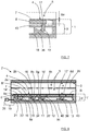
- the E-plane filter 2 comprises a tuning device 1 that comprises a wall part 7.
- the wall part 7 comprises the second inner wall 4, and is movably arranged along an extension that is perpendicular to the intended extension of the electrical field E. In this way, the second length a is adjustable.
- the tuning device 1 is positioned in a tuning housing 42.
- the tuning housing 42 could be formed to be integral with the first part 2a.
- the tuning device 1 furthermore comprises a support part 8 that is arranged to support the wall part 7.
- the wall part 7 is in the form of an electrically conducting foil 7 that is in electrical contact with the third inner wall 5 and the fourth inner wall 6.
- the electrically conducting foil 7 is attached to the third inner wall 5 and the fourth inner wall 6.
- the electrically conducting foil 7 may comprise contact fingers 22 along those edges 31, 32 that are arranged to face the third inner wall 5 and the fourth inner wall 6, where these fingers 22 are arranged to resiliently electrically contacting the third inner wall 5 and the fourth inner wall 6.
- the tuning device 1 comprises an adjustment arrangement 9, where the support part 8 is connected to the adjustment arrangement 9 and where the adjustment arrangement 9 is arranged to displace the support part along an extension that is perpendicular to the intended extension of the electrical field E.
- the adjustment arrangement 9 comprises four support rods 10, 11, 12, 13 that are connected to the support part 8 and extend away from the first inner wall 3.
- the adjustment arrangement 9 further comprises four sloped surfaces 14, 15, 16, 17, one for each support rod 10, 11, 12, 13, each sloped surface 14, 15, 16, 17 being in sliding engagement with a corresponding support rod 10, 11, 12, 13 and being laterally adjustable in the extension of the slope.
- the sloped surfaces 14, 15, 16, 17 that are comprised in corresponding slope blocks 33, 34, 35, 36 are connected to a slide bar 18 that in turn is connected to a screw drive arrangement 19 that is comprised in the adjustment arrangement 9, where a rotational movement of a part of the screw drive arrangement 19 is arranged to laterally displace the slide bar 18.
- the slide bar 18 is moved such that the support rods 10, 11, 12, 13 are displaced towards the first inner wall 3 by means of the sloped surfaces pressing the support rods in that direction, the second inner wall 4 is moved towards the first inner wall 3, which in turn decreases the second length a to a decreased value a- ⁇ a as showed in Figure 6 .
- the slide bar 18 then is moved in the opposite direction, the second length a- ⁇ a will increase and ultimately will be returned to the original value a.
- the decrease of the second distance a with a certain distance ⁇ a is illustrated in detail in Figure 7 .
- the screw drive arrangement 19 comprises an electrical motor 20 that is arranged to run a screw gear 21 that in turn is arranged to displace the slide bar 18 with the slope blocks 33, 34, 35, 36.
- the screw drive arrangement may comprise a manual knob (not shown) arranged for a manual displacement of the slide bar 18 by rotating the manual knob.
- the screw gear 21 may for example be constituted by a threaded rod that engage corresponding threads in an aperture in the tuning housing 42, this is for example suitable in the case of a manual knob.
- the screw gear 21 may comprise an outer housing 44 with internal threads and an inner rod 45 with outer threads, arranged to engage the inner threads of the outer housing 44.
- the outer housing 44 is connected to the electrical motor 20 and is arranged to be brought into rotation by the electrical motor 20.
- the inner rod 45 When the outer housing 44 is rotated by the motor 20, the inner rod 45 is moved along its longitudinal extension, to and from the motor 20, as indicated with an arrow A.
- the inner rod 45 is connected to the slide bar 18 via an aperture in the tuning housing 42, preventing it from rotating along with the outer housing 44 and transferring its movement to the slide bar 18.
- the screw drive arrangement 19 may be more or less, or even completely, positioned within or outside the tuning housing 42.
- the electrically conducting foil 7 is arranged to allow a certain movement when the support part 8 is displaced; for example the electrically conducting foil 7 is resilient in its structure or comprises meandered sections that allow stretching without deformation or rupture.
- the electrically conducting foil 7 should always be subject to a certain pre-tension in order to have a well-defined wall part with a well-defined second inner wall 4.
- well-defined mainly refers to the second length a.
- a foil made as a thin plastic sheet to which an electrically conducting coating is applied may have resilient properties, allowing a certain non-deforming stretch to be performed, which then allows the foil to shrink back when the stretching is discontinued.
- the tuning device 1' comprises a support part 8' that in turn comprises a plurality of sub-parts which are arranged to support the wall part 7, where the wall part 7 also here is in the form of an electrically conducting foil 7 that is attached to the third inner wall 5 and the fourth inner wall 6.
- the sub-parts comprise moveable parts 8a, 8b, 8c, 8d and intermediate parts 8e, 8f, 8g, 8h, 8i, each moveable part 8a, 8b, 8c, 8d being connected to an adjustment arrangement 9' that is arranged to displace the moveable parts 8a, 8b, 8c, 8d along an extension that is perpendicular to the intended extension of the electrical field E.
- the adjustment arrangement comprises the four support rods 10, 11, 12, 13 that are connected to the moveable parts 8a, 8b, 8c, 8d and extend away from the first inner wall 3. There is one support rod 10, 11, 12, 13 for each moveable part 8a, 8b, 8c, 8d.
- the adjustment arrangement further comprises four sloped surfaces 14', 15', 16', 17', one for each support rod 10, 11, 12, 13, each sloped surface 14', 15', 16', 17' being in sliding engagement with a corresponding support rod 10, 11, 12, 13, and being laterally adjustable in the extension of the slope as described for the first example.
- the sloped surfaces 14', 15', 16', 17' are arranged with different slope rates.
- at least one sloped surface 14', 15', 16', 17' is arranged with a slope rate that differs from the other.
- the sloped surfaces 14', 15', 16', 17' are comprised in corresponding slope blocks 33', 34', 35', 36' that are connected to a slide bar 18 that in turn is connected to a screw drive arrangement 19.
- the support rods 10, 11, 12, 13 are displaced towards the first inner wall 3 by means of the sloped surfaces 14', 15', 16', 17' pressing the support rods in that direction, resulting in that the second inner wall 4 is moved towards the first inner wall 3.
- the support rods 10, 11, 12, 13 are displaced towards the first inner wall 3 to different extents, depending on the corresponding slope rates. This results in that the wall part 7 may be moved towards, or away from, the first inner wall 3 to different extents, resulting in that the second length a may vary along the longitudinal extension L.
- the sloped surfaces may have non-linear slope characteristics, for example hyperbolic or discontinuous.
- the sloped surfaces have been shown to be displaced laterally along the longitudinal extension L, but may be displaced in any suitable lateral extension.
- the support rods should be positioned such that they have positions that correspond to the sloped surfaces.
- the movement may be performed manually or electrically controlled.
- an electrical motor may be used, for example a step-motor that is driven digitally to discrete angular axial positions.
- An electrical control may for example be performed via an RJ45 or USB (Universal Serial Bus) connection, or wirelessly, for example via WiFi (Wireless Fidelity).
- a change of filter characteristic by means of wall displacement may be detected, such that desired filter characteristic may be obtained, either manually or automatically.
- tuning device 1 there should be at least one tuning device 1, in addition to the one described and being arranged for the second inner wall 4, there may also be a further tuning device arranged for the first inner wall 3. Such a further tuning device should be arranged in the same, or at least a similar, way as the tuning devices described.
- the E-plane filter 2 is generally referred to as a tuneable waveguide structure 2.
- the wall part may be made in a rigid electrically conducting sheet, or as a thinner foil, as described. All electrically conducting parts may be made as non-conducting part, for example plastic parts, that are covered with an electrically conducting coating.
- An example of a plastic material is polyamide or LCP (Liquid Crystal Polymer), and the electrical coating may for example be made in copper or silver. Other materials and combinations of materials is of course conceivable.
- support rods and corresponding sloped surfaces are advantageous, since this arrangement in combination with a screw gear allows a very fine tuning to be performed. There should be at least two support rods and thus at least two corresponding sloped surfaces.
- the distance between the support rods may differ, as for example depicted in Figure 8 .
- Corresponding slope surfaces, cams or the like are positioned correspondingly.
- the support part 8, or the moveable parts 8a, 8b, 8c, 8d may either be attached to the wall part 7, or may just be in contact with each other.
- a guiding plate 43 may be positioned such that the support rods 10, 11, 12, 13 run through corresponding apertures in the guiding plate 43.
- each wall part 7 is at least indirectly connected to an adjustment arrangement 9.
- the present invention thus relates to a tuning device that comprises at least one wall part 7 that is movably arranged along an extension that is perpendicular to the intended extension of the electrical field E.
- Each wall part 7 is at least indirectly connected to an adjustment arrangement 9 that comprises at least two support rods 10, 11, 12, 13 that are connected to the support part 8 and extend away from the first inner wall 3.
- the adjustment arrangement 9 further comprises a sloped surface 14, 15, 16, 17 for each support rod 10, 11, 12, 13, where each sloped surface 14, 15, 16, 17 is in sliding engagement with a corresponding support rod 10, 11, 12, 13 and also is laterally adjustable in the extension of the slope.
- the wall part may of any suitable type that is arranged to make electrical contact with the third inner wall 5 and the fourth inner wall 6.
- the present invention also relates to a tuning device that comprises at least one wall part 7 that is movably arranged along an extension that is perpendicular to the intended extension of the electrical field E.
- Each tuning device 1 comprises a support part 8 that is arranged to support the wall part 7, where the wall part 7 here is in the form of an electrically conducting foil that is in electrical contact with the third inner wall 5 and the fourth inner wall 6.
- the support part 8 is connected to an adjustment arrangement 9 that is arranged to displace the support part 8 along an extension that is perpendicular to the intended extension of the electrical field E.
- the adjustment arrangement 9 may be of any suitable type, for example the sloped surfaces 14, 15, 16, 17 which are in sliding engagement with corresponding support rods 10, 11, 12, 13 as mentioned above. Other adjustment arrangements not forming part of the invention are conceivable, such as for example screws that directly affect each moveable wall part.
Landscapes
- Physics & Mathematics (AREA)
- Electromagnetism (AREA)
- Engineering & Computer Science (AREA)
- Power Engineering (AREA)
- Control Of Motors That Do Not Use Commutators (AREA)
Claims (14)
- Abstimmbare Wellenleiterstruktur (2), die eine längliche Erweiterung (L) aufweist und eine erste Innenwand (3), eine zweite Innenwand (4), eine dritte Innenwand (5) und eine vierte Innenwand (6) umfasst, wobei die Innenwände (3, 4, 5, 6) durch jeweilige Hauptflächen gebildet sind und elektrisch leitfähig sind, wobei die erste Innenwand (3) und die zweite Innenwand (4) einander zugewandt sind, und wobei die dritte Innenwand (5) und die vierte Innenwand (6) einander zugewandt sind, wobei die beabsichtigte Richtung des elektrischen Feldes (E) parallel zu den Hauptflächen der ersten Innenwand (3) und der zweiten Innenwand (4) ist und wobei die beabsichtigte Richtung des elektrischen Feldes (E) senkrecht zu den Hauptflächen der dritten Innenwand (5) und der vierten Innenwand (6) ist, wobei die abstimmbare Wellenleiterstruktur (2) zumindest eine Abstimmvorrichtung (1) umfasst, wobei die zumindest eine Abstimmvorrichtung einen Wandteil (7) umfasst, und wobei der Wandteil (7) eine von der ersten Innenwand (3) und der zweiten Innenwand (4) umfasst, wobei der Wandteil (7) beweglich in einer Richtung angeordnet ist, die senkrecht zu der beabsichtigten Richtung des elektrischen Feldes (E) und im Wesentlichen senkrecht zu der länglichen Erweiterung (L) ist, dadurch gekennzeichnet, dass die Abstimmvorrichtung (1) eine Einstellungsanordnung (9) umfasst, die wiederum zumindest zwei Stützstangen (10, 11, 12, 13) umfasst, die zumindest indirekt mit dem Wandteil (7) verbunden sind, wobei die Einstellungsanordnung (9) ferner eine geneigte Fläche (14, 15, 16, 17) für jede Stützstange (10, 11, 12, 13) umfasst, wobei jede geneigte Fläche (14, 15, 16, 17) im Wesentlichen parallel zu der ersten und der zweiten Innenwand (3, 4, 5, 6) in der Erweiterung der Neigung und in gleitendem Eingriff mit einer entsprechenden Stützstange (10, 11, 12, 13) beweglich ist, und sodass eine Bewegung einer jeweiligen geneigten Fläche in eine Bewegung der entsprechenden Stützstange umgewandelt wird.
- Abstimmbare Wellenleiterstruktur (2) nach Anspruch 1, dadurch gekennzeichnet, dass die Abstimmvorrichtung (1) einen Stützteil (8) umfasst, der angeordnet ist, um den Wandteil (7) zu stützen, und wobei der Wandteil (7) in der Form einer elektrisch leitfähigen Folie ist, die in elektrischem Kontakt mit der dritten Innenwand (5) und der vierten Innenwand (6) steht, wobei der Stützteil (8) mit der Einstellungsanordnung (9) verbunden ist, die angeordnet ist, um den Stützteil (8) entlang einer Erweiterung zu verschieben, die senkrecht zu der beabsichtigten Erweiterung des elektrischen Feldes (E) ist.
- Abstimmbare Wellenleiterstruktur (2) nach Anspruch 2, dadurch gekennzeichnet, dass der Stützteil (8') bewegliche Teile (8a, 8b, 8c, 8d) und Zwischenteile (8e, 8f, 8g, 8h, 8i) umfasst, die zwischen und neben den beweglichen Teilen (8a, 8b, 8c, 8d) positioniert sind, wobei jeder bewegliche Teil (8a, 8b, 8c, 8d) mit einer entsprechenden Stützstange (10, 11,12, 13) verbunden ist, wobei zumindest eine geneigte Fläche (14', 15', 16', 17') mit einer Neigungsrate angeordnet ist, die sich von der anderen unterscheidet.
- Abstimmbare Wellenleiterstruktur (2) nach einem der vorhergehenden Ansprüche, dadurch gekennzeichnet, dass jede geneigte Fläche (14, 15, 16, 17; 14', 15', 16', 17') in einem entsprechenden Neigungsblock (33, 34, 35, 36; 33', 34', 35', 36') enthalten ist und mit einem Schiebebalken (18) verbunden ist, der wiederum mit einer Schraubentriebanordnung (19) verbunden ist, wobei eine Drehbewegung von zumindest einem Teil der Schraubentriebanordnung (19) angeordnet ist, um den Schiebebalken (18) zu verschieben.
- Abstimmbare Wellenleiterstruktur (2) nach Anspruch 4, dadurch gekennzeichnet, dass die Schraubentriebanordnung (19) einen elektrischen Motor (20) umfasst, der angeordnet ist, um ein Schraubenzahnrad (21) anzutreiben, das wiederum angeordnet ist, um den Schiebebalken (18) zu verschieben.
- Abstimmbare Wellenleiterstruktur (2) nach Anspruch 5, dadurch gekennzeichnet, dass das Schraubenzahnrad (21) ein Außengehäuse (44) mit Innengewinden und eine Innenstange (45) mit Außengewinden umfasst, die angeordnet sind, um die Innengewinde des Außengehäuses (44) in Eingriff zu nehmen, wobei das Außengehäuse (44) mit dem elektrischen Motor (20) verbunden ist und angeordnet ist, um durch den elektrischen Motor (20) in Drehung gebracht zu werden, und wobei die Innenstange (45) mit dem Schiebebalken (18) verbunden ist und angeordnet ist, um sich entlang ihrer länglichen Erweiterung zu bewegen, wenn das Außengehäuse (44) durch den Motor 20 gedreht wird.
- Abstimmbare Wellenleiterstruktur (2) nach Anspruch 2, dadurch gekennzeichnet, dass die elektrisch leitfähige Folie (7) an der dritten Innenwand (5) und der vierten Innenwand (6) angebracht ist.
- Abstimmbare Wellenleiterstruktur (2) nach Anspruch 2, dadurch gekennzeichnet, dass die elektrisch leitfähige Folie (7) Kontaktfinger (22) umfasst, die die dritte Innenwand (5) und die vierte Innenwand (6) elastisch elektrisch verbinden.
- Abstimmbare Wellenleiterstruktur (2) nach einem der vorhergehenden Ansprüche, dadurch gekennzeichnet, dass die Einstellungsanordnung (9) ferner eine Führungsplatte (43) umfasst, die angeordnet ist, um die Stützstangen (10, 11, 12, 13) zu führen, wobei die Stützstangen (10, 11, 12, 13) angeordnet sind, um durch entsprechende Öffnungen in der Führungsplatte (43) zu verlaufen.
- Abstimmbare Wellenleiterstruktur (2) nach einem der vorhergehenden Ansprüche, dadurch gekennzeichnet, dass zumindest eine der geneigten Flächen (14, 15, 16, 17; 14', 15', 16', 17') nichtlineare Neigungseigenschaften aufweist.
- Abstimmbare Wellenleiterstruktur (2) nach Anspruch 2 oder Anspruch 2 und einem der vorhergehenden Ansprüche 3-10, dadurch gekennzeichnet, dass der Stützteil (8') bewegliche Teile (8a, 8b, 8c, 8d) und Zwischenteile (8e, 8f, 8g, 8h, 8i) umfasst, die zwischen und neben den beweglichen Teilen (8a, 8b, 8c, 8d) positioniert sind, wobei jeder bewegliche Teil (8a, 8b, 8c, 8d) mit einer entsprechenden Stützstange (10, 11, 12, 13) verbunden ist, wobei zumindest zwei geneigte Flächen (14', 15', 16', 17') mit Neigungsraten angeordnet sind, die sich von der anderen unterscheiden.
- Abstimmbarer Wellenleiter nach Anspruch 2 oder Anspruch 2 und einem der vorhergehenden Ansprüche 3-11, wobei die elektrisch leitfähige Folie (7) elastisch ist oder mäanderförmige Abschnitte umfasst, die ein Strecken ohne Verformung oder Reißen ermöglichen.
- Abstimmbarer Wellenleiter nach einem vorhergehenden Anspruch, wobei der Wellenleiter eine elektrisch leitfähige Filterfolie (28) umfasst, die den Wellenleiter teilt; wobei die elektrisch leitfähige Filterfolie (28) eine Anzahl an Öffnungen (29, 30) aufweist und parallel zu der ersten Innenwand (3) und der zweiten Innenwand (4) verläuft.
- Abstimmbarer Wellenleiter nach Anspruch 12, wobei die elektrisch leitfähige Filterfolie (28) in einer Ebene angeordnet ist, die im Wesentlichen parallel zu der beabsichtigten Richtung des elektrischen Feldes (E) ist.
Applications Claiming Priority (1)
| Application Number | Priority Date | Filing Date | Title |
|---|---|---|---|
| PCT/EP2014/072157 WO2016058642A1 (en) | 2014-10-15 | 2014-10-15 | An electrically tuneable waveguide structure |
Publications (2)
| Publication Number | Publication Date |
|---|---|
| EP3207587A1 EP3207587A1 (de) | 2017-08-23 |
| EP3207587B1 true EP3207587B1 (de) | 2021-01-20 |
Family
ID=51703186
Family Applications (1)
| Application Number | Title | Priority Date | Filing Date |
|---|---|---|---|
| EP14784090.4A Active EP3207587B1 (de) | 2014-10-15 | 2014-10-15 | Elektrisch abstimmbare wellenleiterstruktur |
Country Status (3)
| Country | Link |
|---|---|
| US (1) | US10236551B2 (de) |
| EP (1) | EP3207587B1 (de) |
| WO (1) | WO2016058642A1 (de) |
Families Citing this family (2)
| Publication number | Priority date | Publication date | Assignee | Title |
|---|---|---|---|---|
| US9899716B1 (en) * | 2015-03-01 | 2018-02-20 | Telefonaktiebolaget Lm Ericsson (Publ) | Waveguide E-plane filter |
| WO2021211026A1 (en) | 2020-04-15 | 2021-10-21 | Telefonaktiebolaget Lm Ericsson (Publ) | A tunable waveguide resonator |
Family Cites Families (4)
| Publication number | Priority date | Publication date | Assignee | Title |
|---|---|---|---|---|
| US5808528A (en) * | 1996-09-05 | 1998-09-15 | Digital Microwave Corporation | Broad-band tunable waveguide filter using etched septum discontinuities |
| EP1885018B1 (de) | 2006-07-24 | 2009-09-02 | Panasonic Corporation | Abstimmbar Bandpassfilter |
| EP2601707A1 (de) | 2010-08-02 | 2013-06-12 | Telefonaktiebolaget Lm Ericsson (publ) | Elektrisch einstellbares wellenleiterfilter und wellenleitereinstellvorrichtung |
| CN103891041B (zh) | 2013-07-04 | 2015-09-30 | 华为技术有限公司 | 滤波器、通信装置及通信系统 |
-
2014
- 2014-10-15 EP EP14784090.4A patent/EP3207587B1/de active Active
- 2014-10-15 US US15/519,291 patent/US10236551B2/en active Active
- 2014-10-15 WO PCT/EP2014/072157 patent/WO2016058642A1/en not_active Ceased
Non-Patent Citations (1)
| Title |
|---|
| None * |
Also Published As
| Publication number | Publication date |
|---|---|
| WO2016058642A1 (en) | 2016-04-21 |
| EP3207587A1 (de) | 2017-08-23 |
| US20170244146A1 (en) | 2017-08-24 |
| US10236551B2 (en) | 2019-03-19 |
Similar Documents
| Publication | Publication Date | Title |
|---|---|---|
| US9887442B2 (en) | RF filter for adjusting coupling amount or transmission zero | |
| US8686810B2 (en) | Frequency tuneable filter using a sliding system | |
| US7180391B2 (en) | Resonator filter | |
| JP5187766B2 (ja) | チューナブル帯域通過フィルタ | |
| US9614265B2 (en) | Variable high frequency filter device and assembly | |
| EP3203633B1 (de) | Nicht-benachbarte multiresonator-kopplung | |
| US8847709B2 (en) | Resonator filter | |
| KR102081950B1 (ko) | 고주파 필터 및 그 튜닝 장치 | |
| CN103262338A (zh) | 可调谐的高频滤波器 | |
| KR20150016069A (ko) | 가변 고주파 필터 장치 및 어셈블리 | |
| US20110133862A1 (en) | Tunable filter capable of controlling tuning characteristics | |
| US20120169435A1 (en) | Microwave and millimeter-wave compact tunable cavity filter | |
| EP3207587B1 (de) | Elektrisch abstimmbare wellenleiterstruktur | |
| WO2006075439A1 (ja) | チューナブルフィルタ、デュプレクサおよび通信機装置 | |
| WO2018069864A1 (en) | Tunable band-pass filter | |
| CN102119466A (zh) | 用于扩大调谐范围的可调滤波器 | |
| KR101216910B1 (ko) | 커플링 양 또는 전송 제로를 조절할 수 있는 rf 필터 | |
| EP1885018B1 (de) | Abstimmbar Bandpassfilter | |
| WO2016174422A2 (en) | A tuneable tem mode microwave resonator and a tuneable microwave filter | |
| CN222191104U (zh) | 一种宽频段可调滤波器及双工器 | |
| WO2018162032A1 (en) | A tunable waveguide filter input/output coupling arrangement | |
| WO2019109735A1 (zh) | 一种可调带宽的波导滤波器 | |
| EP3711113B1 (de) | Abstimmbarer bandpassfilter | |
| WO2018137315A1 (zh) | 一种可调容性交叉耦合结构及腔体滤波器 | |
| KR20110068142A (ko) | 튜닝 특성 및 튜닝 범위 조절이 가능한 튜너블 필터 |
Legal Events
| Date | Code | Title | Description |
|---|---|---|---|
| STAA | Information on the status of an ep patent application or granted ep patent |
Free format text: STATUS: THE INTERNATIONAL PUBLICATION HAS BEEN MADE |
|
| PUAI | Public reference made under article 153(3) epc to a published international application that has entered the european phase |
Free format text: ORIGINAL CODE: 0009012 |
|
| STAA | Information on the status of an ep patent application or granted ep patent |
Free format text: STATUS: REQUEST FOR EXAMINATION WAS MADE |
|
| 17P | Request for examination filed |
Effective date: 20170405 |
|
| AK | Designated contracting states |
Kind code of ref document: A1 Designated state(s): AL AT BE BG CH CY CZ DE DK EE ES FI FR GB GR HR HU IE IS IT LI LT LU LV MC MK MT NL NO PL PT RO RS SE SI SK SM TR |
|
| AX | Request for extension of the european patent |
Extension state: BA ME |
|
| DAX | Request for extension of the european patent (deleted) | ||
| STAA | Information on the status of an ep patent application or granted ep patent |
Free format text: STATUS: EXAMINATION IS IN PROGRESS |
|
| 17Q | First examination report despatched |
Effective date: 20190103 |
|
| GRAP | Despatch of communication of intention to grant a patent |
Free format text: ORIGINAL CODE: EPIDOSNIGR1 |
|
| STAA | Information on the status of an ep patent application or granted ep patent |
Free format text: STATUS: GRANT OF PATENT IS INTENDED |
|
| INTG | Intention to grant announced |
Effective date: 20200722 |
|
| RIN1 | Information on inventor provided before grant (corrected) |
Inventor name: BOLANDER, LARS Inventor name: DELENIV, ANATOLI Inventor name: LIGANDER, PER Inventor name: PERSSON, OVE |
|
| GRAS | Grant fee paid |
Free format text: ORIGINAL CODE: EPIDOSNIGR3 |
|
| GRAA | (expected) grant |
Free format text: ORIGINAL CODE: 0009210 |
|
| STAA | Information on the status of an ep patent application or granted ep patent |
Free format text: STATUS: THE PATENT HAS BEEN GRANTED |
|
| AK | Designated contracting states |
Kind code of ref document: B1 Designated state(s): AL AT BE BG CH CY CZ DE DK EE ES FI FR GB GR HR HU IE IS IT LI LT LU LV MC MK MT NL NO PL PT RO RS SE SI SK SM TR |
|
| REG | Reference to a national code |
Ref country code: GB Ref legal event code: FG4D |
|
| REG | Reference to a national code |
Ref country code: CH Ref legal event code: EP |
|
| REG | Reference to a national code |
Ref country code: DE Ref legal event code: R096 Ref document number: 602014074399 Country of ref document: DE |
|
| REG | Reference to a national code |
Ref country code: AT Ref legal event code: REF Ref document number: 1357162 Country of ref document: AT Kind code of ref document: T Effective date: 20210215 |
|
| REG | Reference to a national code |
Ref country code: IE Ref legal event code: FG4D |
|
| REG | Reference to a national code |
Ref country code: NL Ref legal event code: MP Effective date: 20210120 |
|
| REG | Reference to a national code |
Ref country code: LT Ref legal event code: MG9D |
|
| REG | Reference to a national code |
Ref country code: AT Ref legal event code: MK05 Ref document number: 1357162 Country of ref document: AT Kind code of ref document: T Effective date: 20210120 |
|
| PG25 | Lapsed in a contracting state [announced via postgrant information from national office to epo] |
Ref country code: LT Free format text: LAPSE BECAUSE OF FAILURE TO SUBMIT A TRANSLATION OF THE DESCRIPTION OR TO PAY THE FEE WITHIN THE PRESCRIBED TIME-LIMIT Effective date: 20210120 Ref country code: PT Free format text: LAPSE BECAUSE OF FAILURE TO SUBMIT A TRANSLATION OF THE DESCRIPTION OR TO PAY THE FEE WITHIN THE PRESCRIBED TIME-LIMIT Effective date: 20210520 Ref country code: GR Free format text: LAPSE BECAUSE OF FAILURE TO SUBMIT A TRANSLATION OF THE DESCRIPTION OR TO PAY THE FEE WITHIN THE PRESCRIBED TIME-LIMIT Effective date: 20210421 Ref country code: FI Free format text: LAPSE BECAUSE OF FAILURE TO SUBMIT A TRANSLATION OF THE DESCRIPTION OR TO PAY THE FEE WITHIN THE PRESCRIBED TIME-LIMIT Effective date: 20210120 Ref country code: HR Free format text: LAPSE BECAUSE OF FAILURE TO SUBMIT A TRANSLATION OF THE DESCRIPTION OR TO PAY THE FEE WITHIN THE PRESCRIBED TIME-LIMIT Effective date: 20210120 Ref country code: BG Free format text: LAPSE BECAUSE OF FAILURE TO SUBMIT A TRANSLATION OF THE DESCRIPTION OR TO PAY THE FEE WITHIN THE PRESCRIBED TIME-LIMIT Effective date: 20210420 Ref country code: NO Free format text: LAPSE BECAUSE OF FAILURE TO SUBMIT A TRANSLATION OF THE DESCRIPTION OR TO PAY THE FEE WITHIN THE PRESCRIBED TIME-LIMIT Effective date: 20210420 |
|
| PG25 | Lapsed in a contracting state [announced via postgrant information from national office to epo] |
Ref country code: SE Free format text: LAPSE BECAUSE OF FAILURE TO SUBMIT A TRANSLATION OF THE DESCRIPTION OR TO PAY THE FEE WITHIN THE PRESCRIBED TIME-LIMIT Effective date: 20210120 Ref country code: LV Free format text: LAPSE BECAUSE OF FAILURE TO SUBMIT A TRANSLATION OF THE DESCRIPTION OR TO PAY THE FEE WITHIN THE PRESCRIBED TIME-LIMIT Effective date: 20210120 Ref country code: PL Free format text: LAPSE BECAUSE OF FAILURE TO SUBMIT A TRANSLATION OF THE DESCRIPTION OR TO PAY THE FEE WITHIN THE PRESCRIBED TIME-LIMIT Effective date: 20210120 Ref country code: RS Free format text: LAPSE BECAUSE OF FAILURE TO SUBMIT A TRANSLATION OF THE DESCRIPTION OR TO PAY THE FEE WITHIN THE PRESCRIBED TIME-LIMIT Effective date: 20210120 Ref country code: AT Free format text: LAPSE BECAUSE OF FAILURE TO SUBMIT A TRANSLATION OF THE DESCRIPTION OR TO PAY THE FEE WITHIN THE PRESCRIBED TIME-LIMIT Effective date: 20210120 |
|
| PG25 | Lapsed in a contracting state [announced via postgrant information from national office to epo] |
Ref country code: IS Free format text: LAPSE BECAUSE OF FAILURE TO SUBMIT A TRANSLATION OF THE DESCRIPTION OR TO PAY THE FEE WITHIN THE PRESCRIBED TIME-LIMIT Effective date: 20210520 |
|
| REG | Reference to a national code |
Ref country code: DE Ref legal event code: R097 Ref document number: 602014074399 Country of ref document: DE |
|
| PG25 | Lapsed in a contracting state [announced via postgrant information from national office to epo] |
Ref country code: CZ Free format text: LAPSE BECAUSE OF FAILURE TO SUBMIT A TRANSLATION OF THE DESCRIPTION OR TO PAY THE FEE WITHIN THE PRESCRIBED TIME-LIMIT Effective date: 20210120 Ref country code: EE Free format text: LAPSE BECAUSE OF FAILURE TO SUBMIT A TRANSLATION OF THE DESCRIPTION OR TO PAY THE FEE WITHIN THE PRESCRIBED TIME-LIMIT Effective date: 20210120 Ref country code: SM Free format text: LAPSE BECAUSE OF FAILURE TO SUBMIT A TRANSLATION OF THE DESCRIPTION OR TO PAY THE FEE WITHIN THE PRESCRIBED TIME-LIMIT Effective date: 20210120 |
|
| PLBE | No opposition filed within time limit |
Free format text: ORIGINAL CODE: 0009261 |
|
| STAA | Information on the status of an ep patent application or granted ep patent |
Free format text: STATUS: NO OPPOSITION FILED WITHIN TIME LIMIT |
|
| PG25 | Lapsed in a contracting state [announced via postgrant information from national office to epo] |
Ref country code: DK Free format text: LAPSE BECAUSE OF FAILURE TO SUBMIT A TRANSLATION OF THE DESCRIPTION OR TO PAY THE FEE WITHIN THE PRESCRIBED TIME-LIMIT Effective date: 20210120 Ref country code: SK Free format text: LAPSE BECAUSE OF FAILURE TO SUBMIT A TRANSLATION OF THE DESCRIPTION OR TO PAY THE FEE WITHIN THE PRESCRIBED TIME-LIMIT Effective date: 20210120 Ref country code: RO Free format text: LAPSE BECAUSE OF FAILURE TO SUBMIT A TRANSLATION OF THE DESCRIPTION OR TO PAY THE FEE WITHIN THE PRESCRIBED TIME-LIMIT Effective date: 20210120 |
|
| 26N | No opposition filed |
Effective date: 20211021 |
|
| PG25 | Lapsed in a contracting state [announced via postgrant information from national office to epo] |
Ref country code: ES Free format text: LAPSE BECAUSE OF FAILURE TO SUBMIT A TRANSLATION OF THE DESCRIPTION OR TO PAY THE FEE WITHIN THE PRESCRIBED TIME-LIMIT Effective date: 20210120 Ref country code: AL Free format text: LAPSE BECAUSE OF FAILURE TO SUBMIT A TRANSLATION OF THE DESCRIPTION OR TO PAY THE FEE WITHIN THE PRESCRIBED TIME-LIMIT Effective date: 20210120 |
|
| PG25 | Lapsed in a contracting state [announced via postgrant information from national office to epo] |
Ref country code: SI Free format text: LAPSE BECAUSE OF FAILURE TO SUBMIT A TRANSLATION OF THE DESCRIPTION OR TO PAY THE FEE WITHIN THE PRESCRIBED TIME-LIMIT Effective date: 20210120 |
|
| PG25 | Lapsed in a contracting state [announced via postgrant information from national office to epo] |
Ref country code: IT Free format text: LAPSE BECAUSE OF FAILURE TO SUBMIT A TRANSLATION OF THE DESCRIPTION OR TO PAY THE FEE WITHIN THE PRESCRIBED TIME-LIMIT Effective date: 20210120 |
|
| REG | Reference to a national code |
Ref country code: CH Ref legal event code: PL |
|
| PG25 | Lapsed in a contracting state [announced via postgrant information from national office to epo] |
Ref country code: IS Free format text: LAPSE BECAUSE OF FAILURE TO SUBMIT A TRANSLATION OF THE DESCRIPTION OR TO PAY THE FEE WITHIN THE PRESCRIBED TIME-LIMIT Effective date: 20210520 |
|
| REG | Reference to a national code |
Ref country code: BE Ref legal event code: MM Effective date: 20211031 |
|
| PG25 | Lapsed in a contracting state [announced via postgrant information from national office to epo] |
Ref country code: MC Free format text: LAPSE BECAUSE OF FAILURE TO SUBMIT A TRANSLATION OF THE DESCRIPTION OR TO PAY THE FEE WITHIN THE PRESCRIBED TIME-LIMIT Effective date: 20210120 |
|
| PG25 | Lapsed in a contracting state [announced via postgrant information from national office to epo] |
Ref country code: LU Free format text: LAPSE BECAUSE OF NON-PAYMENT OF DUE FEES Effective date: 20211015 Ref country code: BE Free format text: LAPSE BECAUSE OF NON-PAYMENT OF DUE FEES Effective date: 20211031 |
|
| PG25 | Lapsed in a contracting state [announced via postgrant information from national office to epo] |
Ref country code: LI Free format text: LAPSE BECAUSE OF NON-PAYMENT OF DUE FEES Effective date: 20211031 Ref country code: CH Free format text: LAPSE BECAUSE OF NON-PAYMENT OF DUE FEES Effective date: 20211031 |
|
| PG25 | Lapsed in a contracting state [announced via postgrant information from national office to epo] |
Ref country code: FR Free format text: LAPSE BECAUSE OF NON-PAYMENT OF DUE FEES Effective date: 20211031 |
|
| PG25 | Lapsed in a contracting state [announced via postgrant information from national office to epo] |
Ref country code: IE Free format text: LAPSE BECAUSE OF NON-PAYMENT OF DUE FEES Effective date: 20211015 |
|
| PG25 | Lapsed in a contracting state [announced via postgrant information from national office to epo] |
Ref country code: HU Free format text: LAPSE BECAUSE OF FAILURE TO SUBMIT A TRANSLATION OF THE DESCRIPTION OR TO PAY THE FEE WITHIN THE PRESCRIBED TIME-LIMIT; INVALID AB INITIO Effective date: 20141015 |
|
| PG25 | Lapsed in a contracting state [announced via postgrant information from national office to epo] |
Ref country code: NL Free format text: LAPSE BECAUSE OF NON-PAYMENT OF DUE FEES Effective date: 20210120 Ref country code: CY Free format text: LAPSE BECAUSE OF FAILURE TO SUBMIT A TRANSLATION OF THE DESCRIPTION OR TO PAY THE FEE WITHIN THE PRESCRIBED TIME-LIMIT Effective date: 20210120 |
|
| PG25 | Lapsed in a contracting state [announced via postgrant information from national office to epo] |
Ref country code: MK Free format text: LAPSE BECAUSE OF FAILURE TO SUBMIT A TRANSLATION OF THE DESCRIPTION OR TO PAY THE FEE WITHIN THE PRESCRIBED TIME-LIMIT Effective date: 20210120 |
|
| PG25 | Lapsed in a contracting state [announced via postgrant information from national office to epo] |
Ref country code: MT Free format text: LAPSE BECAUSE OF FAILURE TO SUBMIT A TRANSLATION OF THE DESCRIPTION OR TO PAY THE FEE WITHIN THE PRESCRIBED TIME-LIMIT Effective date: 20210120 |
|
| PG25 | Lapsed in a contracting state [announced via postgrant information from national office to epo] |
Ref country code: TR Free format text: LAPSE BECAUSE OF FAILURE TO SUBMIT A TRANSLATION OF THE DESCRIPTION OR TO PAY THE FEE WITHIN THE PRESCRIBED TIME-LIMIT Effective date: 20210120 |
|
| PGFP | Annual fee paid to national office [announced via postgrant information from national office to epo] |
Ref country code: DE Payment date: 20251029 Year of fee payment: 12 |
|
| PGFP | Annual fee paid to national office [announced via postgrant information from national office to epo] |
Ref country code: GB Payment date: 20251027 Year of fee payment: 12 |