EP3711113B1 - Abstimmbarer bandpassfilter - Google Patents
Abstimmbarer bandpassfilter Download PDFInfo
- Publication number
- EP3711113B1 EP3711113B1 EP18819389.0A EP18819389A EP3711113B1 EP 3711113 B1 EP3711113 B1 EP 3711113B1 EP 18819389 A EP18819389 A EP 18819389A EP 3711113 B1 EP3711113 B1 EP 3711113B1
- Authority
- EP
- European Patent Office
- Prior art keywords
- resonant
- perturbator
- filter
- resonant cavity
- cavities
- Prior art date
- Legal status (The legal status is an assumption and is not a legal conclusion. Google has not performed a legal analysis and makes no representation as to the accuracy of the status listed.)
- Active
Links
Images

Classifications
-
- H—ELECTRICITY
- H01—ELECTRIC ELEMENTS
- H01P—WAVEGUIDES; RESONATORS, LINES, OR OTHER DEVICES OF THE WAVEGUIDE TYPE
- H01P1/00—Auxiliary devices
- H01P1/20—Frequency-selective devices, e.g. filters
- H01P1/201—Filters for transverse electromagnetic waves
- H01P1/205—Comb or interdigital filters; Cascaded coaxial cavities
- H01P1/2053—Comb or interdigital filters; Cascaded coaxial cavities the coaxial cavity resonators being disposed parall to each other
Definitions
- the present invention concerns a tunable band-pass filter also referred to as a tunable filter with metal cylinders or "tunable band-pass filter based on metal post technology" and a method to tune the pass band of a band-pass filter.
- the band-pass filter according to the present invention can be the radiofrequency or microwave type, which allows to reconfigure its electrical response in frequency thanks to a mechanism for tuning the resonance frequency of the resonant cavities which make up the filter.
- Filters used in microwave and radiofrequency systems are known, to allow the passage of a generally narrow portion of the spectrum of frequencies and which enable the other frequencies to be suitably attenuated, sometimes at discretion until the unwanted frequencies are eliminated.
- band-pass filters with metal cylinders made in cavities, or metal waveguides are used in radiofrequency transmission/reception systems for applications in which fundamental requirements are: low insertion losses in the electrical response, reduced bulk compared to other technologies, and high operating power.
- a known band-pass filter with metal cylinders is used for operating frequencies lower than 10-15GHz.
- the use of other types of filters, having low losses, such as rectangular or circular guide filters, would entail significant bulk.
- a known band-pass filter with metal cylinders comprises a plurality of resonant units or resonators disposed one after the other and connected to each other.
- Each resonant unit is provided with a resonant cavity and, at least, a first aperture and a second aperture, respectively an input aperture and an output aperture of the electromagnetic field.
- the output aperture of one of the resonant units is directly connected to the input aperture of the next resonant unit through a guide channel, also called an iris diaphragm.
- Each resonant cavity is defined by metal surfaces and comprises a protruding element with metal surfaces, also referred to in the specific field as metal cylinder or "metal post", which protrudes from one of the surfaces defining the resonant cavity toward the inside of the latter.
- the resonant units usually more than two, are made in a single body or by connecting two or more components, together defining the band-pass filter.
- the number "N” of resonant units of a filter defines the so-called order of the filter: a filter with "N" resonant units is an "N" order filter.
- the particular conformation of the filter that is, the sizes of the resonant cavities, the sizes of the iris diaphragms, the types of metal materials used, allow to define a predefined filtering band of the electromagnetic waves.
- the screw is screwed into a through hole made in the protruding element, and the extent by which the screw is screwed determines how far the end protrudes into the resonant cavity.
- the length of the protruding part of the screw allows to define the entity of the adjustment of the pass band of the filter.
- the connecting iris diaphragm between pairs of resonant cavities extends over the entire height of the latter, that is, from the bottom wall, in which the protruding elements are attached, to the upper wall, which normally closes the resonant cavity.
- the iris diaphragms are made starting from the upper wall of the resonant cavities and extend toward the bottom wall, but remaining at a predefined distance from the bottom wall where the protruding elements are attached.
- EP-A-2814112 A1 discloses a resonator assembly comprising a first resonance and a second resonance post located in a same cavity, both operable to filter a signal at respective frequencies, and a signal coupling configured to couple the signal to a resonator output.
- the resonator makes it possible to provide an adaptable single device which implements more than one independent resonance within the same cavity volume, allowing to build significantly smaller cavity filters and which avoids the need to provide separate devices.
- US-B-6198363 B1 describes a filter and frequency tuning element comprising a plurality of cavities separated by walls, and wherein the walls that separate two cavities are provided with coupling holes, to provide a better coupling of the cavities.
- EP-A-2833473 A1 discloses a tunable filter comprising a plurality of resonance cavities, where a resonance tube and a tuning bolt are disposed in each resonance cavity, and the tuning blot penetrates into a space enclosed by the resonance tube.
- a tuning part is also disposed between the tuning bolt and the resonance tube.
- a driving unit is also disclosed that may drive an adjusting structure used for rotating the tuning part.
- this solution does not allow to obtain localized and/or different reconfigurations for the different resonant units defining the band-pass filter.
- One purpose of the present invention is therefore to provide a tunable band-pass filter which performs better than known tunable guide filters.
- Another purpose of the invention is to provide a tunable band-pass filter which is efficient in allowing to reduce insertion or attenuation losses in the pass band, compared with known solutions.
- Another purpose of the invention is to provide a tunable band-pass filter which allows to increase the operating power with low losses and reduced bulk compared to other technologies, such as guide filters.
- Another purpose of the invention is to provide a tunable band-pass filter in which the form of the response of the filter does not deform with tuning.
- Another purpose of the invention is to provide a tunable band-pass filter which allows to correct possible manufacturing errors which can negatively influence the form of the electrical response of the filter, adjusting independently and with small deviations the different resonators with mobile elements that are independent from each other.
- Another purpose of the invention is to provide a tunable band-pass filter which is simple and economical to make.
- the Applicant has devised, tested and embodied the present invention to overcome the shortcomings of the state of the art and to obtain these and other purposes and advantages.
- the solution of the tunable band-pass filter according to the present invention allows to increase performances and achieve a finer tuning of the frequency in response with respect to known solutions thanks to the presence of the mobile perturbator elements associated with each protruding element.
- the present invention does not require the presence of electric circuits or electric control lines or polarization inside the filter itself.
- the presence of the mobile perturbator element, of the mechanical type allows to contain production costs, improve reliability and resistance to mechanical stress
- the present invention also concerns a method to tune the pass band of a band-pass filter.
- the modification of the pass band determines a variation in the frequency of the electromagnetic field and the band width of the electromagnetic field.
- the present invention concerns a band-pass filter indicated in its entirety by the reference number 10.
- the filter 10 according to the present invention can be configured to adjust the operating frequency of its pass band in the case of applications having operating frequency usually lower than 15GHz, for example comprised between 2GHz and 8GHz.
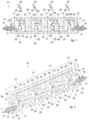
- the filter 10 comprises a plurality of resonant units 11 disposed one after the other and connected to each other so as to define together a guide channel 12, which extends between an input end 13 from which the electromagnetic field can penetrate and an output end 14 in which the electromagnetic field exits after being filtered.
- the resonant units 11 can be reciprocally connected to each other to define a guide channel 12 which extends along a transmission path P of the electromagnetic signal indicated in figs. 1, 2 and 7 with a broken line.
- the guide channel 12 can define a rectilinear transmission path P.
- This solution makes the filter 10 particularly easy to make and to adjust.
- the transmission path P can be defined by consecutive non-collinear segments, that is, to define a broken line.
- This solution allows to obtain a tunable filter 10 which can be adapted to the specific constructional and installation requirements required, for example, by dimensional constraints of the specific application.
- an input device 15 and an output device 16 of the electromagnetic field are respectively connected.
- the input device 15 and the output device 16 of the electromagnetic field can comprise at least one electrical connector 17 ( figs. 1 and 2 ).
- the input device 15 and the output device 16 comprise a waveguide 18 ( fig. 7 ), in this specific case a rectangular guide for the introduction and exit of the electromagnetic field.
- the input device 15 is connected to a first of the resonant units 11, and the output device 16 is connected to a second of the resonant units 11.
- the first and second resonant unit 11 can be located respectively at the input end and the output end of the transmission path P.
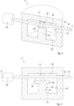
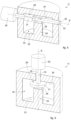
- resonant units 11 are shown schematically in figs. 3-6 , and can be reciprocally combined to define the tunable band-pass filter 10 according to the present invention.
- Each resonant unit 11 is provided with a resonant cavity 19, and the resonant cavities 19, in turn, are connected to each other to define the guide channel 12.
- the resonant cavities 19 can have substantially all the same shape and size.
- the resonant cavities 19 can have different shape and/or sizes. This solution allows to have greater degrees of freedom in the design of the filter 10.
- the resonant cavities 19 can have a cylindrical conformation.
- the resonant cavities 19 can have a prismatic conformation.
- the resonant cavities 19 have an ellipsoidal conformation.
- the resonant cavities 19 can be provided with at least one input aperture 20 and an output aperture 21 of the electromagnetic field.
- the resonant cavities 19, of adjacent resonant units 11, are connected by respective channel portions 22, also called iris diaphragms.
- the channel portions 22 connect the output aperture 21 of a first of the resonant units 11 with the input aperture 20 of a second of the resonant units 11, adjacent and consecutive to the first resonant unit 11.
- the sizes of the input apertures 20 and of the output apertures 21 of the resonant cavities 19 define the pass band amplitude and the level of adaptation of the electromagnetic signal that the filter 10 is able to have in its electrical response.
- the resonant cavities 19 are defined by one or more surfaces made of and/or coated with a metal material.
- a metal material allows to contain and guide the electromagnetic field along the guide channel 12.
- the whole resonant unit 11 can be made of a metal material, so that also the surfaces defining the resonant cavity 19 are metal.
- the resonant units 11 are made of a material chosen from a group comprising steel, copper or aluminum.
- the resonant unit 11 can be made of a dielectric material, for example a plastic material, and in which all the surfaces defining the resonant cavity 19 are coated with the metal material.
- the metal material can be chosen from a group comprising copper, silver, gold, or suchlike.
- the coating of the resonant cavity 19 can be carried out by vapor deposition techniques, for example sputtering techniques, or Chemical or Physical Vapor Deposition.
- the resonant cavities 19 can be defined by at least one base surface 23 and an upper surface 24, opposite the base surface 23.
- the input apertures 20 and the output apertures 21, or also the channel portions 22 interposed between them are positioned at the height of the base surface 23. This positioning allows to increase the stability of the frequency response of the filter during tuning, in practice obtaining a coupling of stable adjacent cavities as the operating frequency varies, thanks to the particular position of the input and output apertures which are located in a zone where the electromagnetic field is not very sensitive to alterations in the field that occur during the tuning of the operating frequency.
- the base surfaces 23 of all the resonant units 11 are located on the same lying plane, and are connected to each other with surfaces defining said input apertures 20 and output apertures 21.
- the channel portions 22 extend from, that is, start from, the base surfaces 23, and are distanced from the upper surfaces 24 defining the resonant cavities 19, that is, they do not reach the upper surfaces 24.
- the channel portions 22 have a height lower than the height of the resonant cavities 19, and the height is determined in a direction incident to the base surface 23. This solution too allows to further increase the stability of the frequency response of the filter.
- the electric connectors 17 of the input 15 and output devices 16 are connected in proximity to the base surfaces 23 of the resonant cavities 19.
- connection of the electric connectors 17 in the resonant cavities 19 allows to define also the functioning parameters of the filter 10, that is, its pass band.
- each resonant cavity 19 is provided with a protruding element 25 which has at least its surfaces located in the resonant cavity 19 made of metal.
- the protruding element 25 is also referred to, in the specific field, as metal cylinder or "metal post", and protrudes from one of the surfaces defining the resonant cavity 19 and toward the inside thereof.
- each protruding element 25 has an extension axis which intersects the transmission path P.
- the protruding element 25 has a height H1 which is greater than the height H2 of the channel portion 22.
- the heights H1 and H2 are determined in a direction that is incident, preferably orthogonal, to the base surface 23. This allows to increase the stability of the frequency response of the filter during tuning, in practice obtaining couplings of stable adjacent cavities as the operating frequency varies.
- the protruding element 25 defines an internal resonator of the resonant cavity 19.
- the protruding element 25 can be made in a single body with the resonant unit 11. This solution allows to contain the insertion losses to which the filter is subjected during use, since interruptions to the current lines that occur in the resonant cavity 19 are minimized.
- the protruding element 25 can be made as a separate component and subsequently connected to the resonant unit 11, for example with mechanical connections, or glues, or welding. This allows to considerably simplify the operations of making the filter 10, consequently reducing the costs thereof.
- the protruding element 25 can be made of an electrically conductive material or, according to a variant, at least the peripheral surfaces located in the resonant cavity 19 are coated with an electrically conductive material, that is, a metal.
- the protruding element 25 is located protruding from the base surface 23 of the resonant cavity 19, in a direction incident to the base surface 23.
- the protruding member 25 is provided with an end surface 26 which faces the upper surface 24 of the resonant cavity 19.
- the reciprocal distance between the end surface 26 of the protruding element 25 and the upper surface 24 conditions the frequency response of the filter 10, according to the present invention.
- the end surface 26 and the upper surface 24 define a structure similar to the plates of an electric capacitor, considerably influencing the resonance frequency of the protruding element 25 and consequently the operating frequency of the filter.
- the protruding element 25 can have a cylindrical shape ( figs. 2 and 3 ) or prismatic.
- the protruding element 25 can have a cross-section of variable size and/or shape along the axis of development of the protruding element 25.
- the protruding element 25 can be defined by a base portion 27 connected to one of the surfaces defining the resonant cavity 19, in this specific case connected to the base surface 23, and by an end portion 28 connected to the base portion 27 and defining the terminal end of the resonant cavity 19 which is positioned in the resonant cavity 19.
- the end portion 28 can have cross-section sizes, that is, transverse to the axis according to which the protruding element 25 protrudes, greater than the base portion 27.
- This solution allows to increase the surface extension of the end surface 26 of the protruding element 25, and therefore, by increasing the electrical capacity at the end of the protruding element 25, it can further condition the operating frequency.
- This solution allows to obtain a filter 10 which, given the same frequency response, has smaller sizes of the protruding element 25.
- this solution allows to increase the performance of the filter 10 by reducing the problems of response of the band-pass which generate perturbations due to the resonance modes of an order higher than the first.
- At least one of the resonant units 11 of the filter 10 comprises a perturbator body 29 positioned in the resonant cavity 19, and a movement member 30 positioned outside the perturbator body 29 and configured to move the perturbator body 29 in the resonant cavity 19.
- the function of the perturbator body 29 is to suitably perturb the electromagnetic field passing through the guide channel 12, without altering it excessively and compromising the resonance of the field itself and therefore the stability of the electrical response of the filter 10.
- the perturbator body 29 is positioned in the space comprised between the protruding element 25 and the surfaces defining the resonant cavity 19.
- the perturbator body 29 is installed in the interspace between the upper surface 24 of the resonant cavity 19 and the end surface 26 of the protruding element 25.
- This positioning of the perturbator body 29 allows to modify the frequency response of the electromagnetic field, in relation to the different position assumed by the perturbator body 29.
- the perturbator bodies 29 installed in the resonant cavities 19 have the same shape and size. This solution allows to obtain a modular and low cost structure.
- the perturbator bodies 29 have different shape and/or sizes, or at least some of them have.
- the use of perturbator bodies 29 of different shapes allows, for example in applications in which it is not possible to use perturbation bodies all of the same shape and size, to obtain a correct tuning of the response of the filter.
- the perturbator bodies 29 are installed in the resonant cavity 19 aligned along the transmission path P.
- the perturbator bodies 29 can be made, or at least one part made, with a dielectric material.
- dielectric materials for example ceramic with high relative permittivity (>10), allows to perturb the electromagnetic field significantly, while at the same time containing insertion losses.
- the perturbator bodies 29 can be made of a metal material. This solution allows to simplify the operations of making the perturbator bodies 29, making them particularly economical. Moreover, the use of metal material makes the perturbator bodies 29 particularly resistant and usable for greater tuning intervals, given the same sizes.
- the perturbator bodies 29 can be made partly of a metal material and partly of a dielectric material. This solution facilitates the construction of the perturbator bodies 29.
- the perturbator bodies 29 can be coated on the surface with a metal layer, for example with one or the other of the metallization techniques described above.
- the perturbator bodies 29 can comprise a perturbator element 31 and at least one support shaft 32 configured to support the perturbator element 31 in the resonant cavity 19.
- the perturbator element 31 can be plate-shaped.
- the perturbator element 31 can have any shape whatsoever, even irregular.
- the perturbator element 31 does not have a circular symmetry with respect to its axis of rotation.
- the perturbator element 31 has a symmetrical conformation with respect to at least one axis of symmetry and the support shaft 32 is configured to support the perturbator element 31 around the axis of symmetry.
- the support shaft 32 is configured to support the perturbator element 31 on a non-symmetrical axis of the perturbator element 31.
- the perturbator element 31 can have a rectangular shape and be supported by the support shaft 32 in correspondence with the center line of the perturbator element 31.
- the support shaft 32 can be configured to support the perturbator element 31 on opposite sides of the latter.
- the support shaft 32 is configured to support the perturbator element 31 with a free end thereof, that is, to support the perturbator element 31 in a cantilevered manner.
- the support shafts 32 can be installed in the resonant units 11 with respective support elements, not shown.
- the support elements can be chosen from a group comprising at least one of either a bushing, a sleeve or a bearing.
- the resonant units 11 can be provided with support seatings 33 configured to support and allow movement of the perturbator bodies 29.
- the support seatings 33 are installed on the support shafts 32.
- the perturbator bodies 29 are selectively rotatable, as described hereafter, around respective axes X, located transverse to the transmission path P and, in this specific case, transverse to the protruding axis of the protruding element 25.
- the perturbator bodies 29 can be movable linearly along an axis X.
- the perturbator bodies 29 can be moved linearly toward/away from the protruding element 25 in order to modify, in this way, the frequency response.
- the perturbator bodies 29 can be moved both linearly and made to rotate with respect to an axis X thereof, as indicated by the arrows shown in fig. 5 .
- the axes X of the perturbator bodies 29 can coincide with the axes of the support shafts 32.
- the movement member 30 is the mechanical type and this prevents possible electromagnetic interference with the electromagnetic field that passes through the guide channel 12.
- the positioning of the movement member 30 outside the resonant cavity 19 allows to reduce electromechanical losses and therefore to increase the efficiency of the filter 10. Furthermore, this positioning facilitates the operations to adjust the tuning of the filter 10.
- the movement member 30 can be chosen from a group comprising at least one of either a gear mechanism, a motor, a linear actuator, an articulated mechanism, an actuation lever or crank or a possible combination of the above.
- the movement member 30 is configured to adjust at least the angular position of the perturbator body 29 with respect to the axis X.
- the rotation needed to obtain the maximum perturbation effect of the resonance frequency can be even only 90°.
- the movement member 30 ( fig. 6 ) can be configured to move the perturbator body 29 linearly in the respective resonant cavity 19.
- the movement member 30 is configured to move the perturbator body 29 linearly and in a direction parallel to the axis X defined above, in order to modify its position in the resonant cavity 19, for example toward/away from the end surface 26.
- the movement member 30 can be configured to move the at least one perturbator body 29 in a combined manner, both linear and rotary.
- all the resonant units 11 of the filter 10 are provided with their own perturbator body 29.
- each perturbator body 29 is connected to a respective and independent movement member 30.
- This solution allows to adjust the non-synchronized position of the perturbator bodies 29, for example if it is necessary to correct errors of manufacture (which can negatively influence the form of the electrical response of the filter), or if it is necessary to tune the different resonators independently and by small quantities with perturbator bodies that are independent of one another.
- the perturbator bodies 29 are all connected to a single movement member 30. This allows to obtain a synchronous adjustment of the position for all the perturbator bodies 29.
- This solution allows to obtain a synchronous tuning, that is, of the same frequency value, of all the resonators of the filter. This allows to obtain a stable tuning of the response of the filter 10, preventing undesired variations in the response of the filter as the frequency changes.
- the at least one movement member 30 can be connected to the perturbator body 29 in correspondence with the support shaft 32 thereof.
- the support shaft 32 extends through, in the support seating 33 made in the resonant unit 11, and has a free end located outside the latter and connected to the movement member 30.
- At least two of the perturbator bodies 29 are reciprocally connected to one another, so that the movement of one determines the movement of the other as well.
- the perturbator element 31 of a first perturbator body 29 and the perturbator element 31 of a second perturbator body 29 are installed on the same support shaft 32.
- pairs of perturbator elements 31, each installed in a respective resonant cavity 19, are associated with the same support shaft 32 installed between the respective resonant units 11. Such variant is not part of the invention.
- a variant embodiment shown in fig. 8 , if the resonant units 11 are aligned along a rectilinear transmission path P, it can be provided that the perturbator elements 31 of each of the resonant units 11 are all installed on a common support shaft 32. Such variant is not part of the invention.
- the support shaft 32 can be installed passing through the resonant cavities 19 of the resonant units 11.
- the filter 10 can comprise a base body 34 and at least one covering body 35 coupled with the base body 34 to define, together, the resonant units 11.
- the base body 34 and the covering body 35 define, together, the resonant cavities 19 reciprocally connected to each other by the channel portions 22 of the guide channel 12.
- connection elements for example mechanical.
- connection elements can be chosen from a group comprising threaded connection elements, plugs, pins, or suchlike.
- the base body 34 can define the resonant cavities 19 and the guide channel 12 in which the protruding elements 25 are disposed.
- the covering body 35 is located to close the resonant cavities 19 at the top.
- the filter 10 comprises an intermediate body 36 interposed between the covering body 35 and the base body 34 and in which the perturbator bodies 29 are positioned.
- the intermediate body 36 is provided with a plurality of through apertures defining, in use, part of the resonant cavities 19 of the resonant units 11.
- the intermediate body 36 and the covering body 35 can be provided with grooves, made in coordinated positions, and defining, when coupled together, the support seatings 33 for the support shaft 32.
Landscapes
- Physics & Mathematics (AREA)
- Electromagnetism (AREA)
- Control Of Motors That Do Not Use Commutators (AREA)
Claims (7)
- Abstimmbares Bandpassfilter, aufweisend eine Mehrzahl von Resonanzeinheiten (11), die jeweils mit einem Resonanzhohlraum (19) versehen sind, in dem sich ein vorstehendes Element (25) befindet, das von einer Grundfläche (23) des Resonanzhohlraums (19) und in Richtung des Inneren des letzteren vorsteht, wobei die Resonanzhohlräume (19) miteinander verbunden sind, um einen Führungskanal (12) für den Durchgang eines elektromagnetischen Feldes zu definieren, wobei mindestens eine der Resonanzeinheiten (11) einen Störkörper (29), der in dem entsprechenden Resonanzhohlraum (19) positioniert ist, und ein Bewegungselement (30) aufweist, das außerhalb des Resonanzhohlraums (19) positioniert ist und konfiguriert ist, um den Störkörper (29) in dem Resonanzhohlraum (19) zu bewegen; wobei die Resonanzhohlräume (19) der Resonanzeinheiten (11) durch entsprechende Kanalabschnitte (22) miteinander verbunden sind und die Kanalabschnitte (22) auf der Höhe der Grundfläche (23) angeordnet sind;
wobei das mindestens eine Bewegungselement (30) konfiguriert ist, zumindest die Winkelposition des mindestens einen Störkörpers (29) einzustellen und den mindestens einen Störkörper (29) linear in dem entsprechenden Resonanzhohlraum (19) zu bewegen, und wobei jeder Störkörper (29) mit einem entsprechenden und unabhängigen Bewegungselement (30) verbunden ist. - Filter nach Anspruch 1, dadurch gekennzeichnet, dass die Resonanzhohlräume (19) durch die Grundfläche (23) und durch eine der Grundfläche (23) gegenüberliegende obere Fläche (24) definiert sind, und dadurch, dass sich die Kanalabschnitte (22) von den Grundflächen (23) aus erstrecken und von den oberen Flächen (24) beabstandet sind.
- Filter nach Anspruch 1 oder 2, dadurch gekennzeichnet, dass die vorstehenden Elemente (25) eine Höhe (H1) haben, die größer ist als die Höhe (H2) des Kanalabschnitts (22), wobei die Höhen (H1, H2) in einer Richtung senkrecht zur Grundfläche (23) bestimmt werden.
- Filter nach einem der vorhergehenden Ansprüche, dadurch gekennzeichnet, dass sich die Grundflächen (23) aller Resonanzeinheiten (11) auf derselben liegenden Ebene befinden.
- Filter nach einem der vorhergehenden Ansprüche, dadurch gekennzeichnet, dass die Resonanzhohlräume (19) durch eine Grundfläche (23), von der aus die vorstehenden Elemente (25) vorstehend angeordnet sind, und durch eine der Grundfläche (23) gegenüberliegende obere Fläche (24) definiert sind, dadurch, dass die vorstehenden Elemente (25) jeweils eine der oberen Fläche (24) zugewandte Endfläche (26) aufweisen, und dadurch, dass die Störkörper (29) in dem Zwischenraum, der zwischen der oberen Fläche (24) und der Endfläche (26) vorhanden ist, installiert sind.
- Filter nach einem der vorhergehenden Ansprüche, dadurch gekennzeichnet, dass die Störkörper (29) ein Störelement (31) und mindestens einen Stützschaft (32) aufweisen, der konfiguriert ist, um das Störelement (31) in dem Resonanzhohlraum (19) zu stützen.
- Verfahren zum Abstimmen des Durchlassbandes eines Bandpassfilters, das dafür sorgt, dass ein elektromagnetisches Feld durch einen Führungskanal (12) läuft, der durch eine Mehrzahl von Resonanzhohlräumen (19) von entsprechenden Resonanzeinheiten (11) definiert ist, die miteinander verbunden sind, wobei jeder Hohlraum aufweist:
ein vorstehendes Element (25), das von einer der Flächen hervorsteht, die den Resonanzhohlraum (19) definieren, das in den Resonanzhohlräumen (19) angeordnet ist, wobei die Resonanzhohlräume (19) der Resonanzeinheiten (11) miteinander durch entsprechende Kanalabschnitte (22) verbunden sind, die auf der Höhe der Grundfläche (23) positioniert sind, wobei die Bewegungselemente (30) konfiguriert sind, zumindest die Winkelposition der Störkörper (29) einzustellen und die Störkörper (29) linear in den entsprechenden Resonanzhohlräumen (19) zu bewegen, und wobei jeder Störkörper (29) mit einem entsprechenden und unabhängigen Bewegungselement (30) verbunden ist, wobei das Verfahren ferner aufweist: Bewegen des Störkörpers (29) in mindestens einem der Resonanzhohlräume (19) durch ein Bewegungselement (30), das außerhalb des Resonanzraumes (19) angeordnet ist, um das Durchlassband des Bandpassfilters durch eine Störung des elektromagnetischen Feldes, das sich im Inneren des Führungskanals (12) befindet, zu verändern.
Applications Claiming Priority (2)
| Application Number | Priority Date | Filing Date | Title |
|---|---|---|---|
| IT201700131316 | 2017-11-16 | ||
| PCT/IT2018/050222 WO2019097559A1 (en) | 2017-11-16 | 2018-11-16 | Tunable band-pass filter |
Publications (2)
| Publication Number | Publication Date |
|---|---|
| EP3711113A1 EP3711113A1 (de) | 2020-09-23 |
| EP3711113B1 true EP3711113B1 (de) | 2024-01-17 |
Family
ID=61527317
Family Applications (1)
| Application Number | Title | Priority Date | Filing Date |
|---|---|---|---|
| EP18819389.0A Active EP3711113B1 (de) | 2017-11-16 | 2018-11-16 | Abstimmbarer bandpassfilter |
Country Status (2)
| Country | Link |
|---|---|
| EP (1) | EP3711113B1 (de) |
| WO (1) | WO2019097559A1 (de) |
Citations (1)
| Publication number | Priority date | Publication date | Assignee | Title |
|---|---|---|---|---|
| EP2833473A1 (de) * | 2012-04-28 | 2015-02-04 | Huawei Technologies Co., Ltd. | Abstimmbares filter und duplexer mit dem abstimmbaren filter |
Family Cites Families (5)
| Publication number | Priority date | Publication date | Assignee | Title |
|---|---|---|---|---|
| FI87405C (fi) * | 1990-02-07 | 1992-12-28 | Lk Products Oy | Hoegfrekvensfilter |
| FI106658B (fi) * | 1997-12-15 | 2001-03-15 | Adc Solitra Oy | Suodatin ja säätöelin |
| KR100769657B1 (ko) * | 2003-08-23 | 2007-10-23 | 주식회사 케이엠더블유 | 무선 주파수 대역 가변 필터 |
| JP6006079B2 (ja) * | 2012-10-23 | 2016-10-12 | Necエンジニアリング株式会社 | チューナブル帯域通過フィルタ |
| EP2814112A1 (de) * | 2013-06-13 | 2014-12-17 | Alcatel Lucent | Resonatoranordnung |
-
2018
- 2018-11-16 EP EP18819389.0A patent/EP3711113B1/de active Active
- 2018-11-16 WO PCT/IT2018/050222 patent/WO2019097559A1/en not_active Ceased
Patent Citations (1)
| Publication number | Priority date | Publication date | Assignee | Title |
|---|---|---|---|---|
| EP2833473A1 (de) * | 2012-04-28 | 2015-02-04 | Huawei Technologies Co., Ltd. | Abstimmbares filter und duplexer mit dem abstimmbaren filter |
Also Published As
| Publication number | Publication date |
|---|---|
| WO2019097559A1 (en) | 2019-05-23 |
| EP3711113A1 (de) | 2020-09-23 |
Similar Documents
| Publication | Publication Date | Title |
|---|---|---|
| US7180391B2 (en) | Resonator filter | |
| CN103262338B (zh) | 可调谐的高频滤波器 | |
| FI88979C (fi) | Hoegfrekvensbandpassfilter | |
| EP3050212B1 (de) | Nicht-benachbarte multiresonator-kupplung | |
| EP2913884B1 (de) | Einstellbarer bandpassfilter | |
| FI123439B (fi) | Säädettävä resonaattorisuodin ja menetelmä resonaattorionteloiden välisen kytkennän säätämiseksi | |
| US9083071B2 (en) | Microwave and millimeter-wave compact tunable cavity filter | |
| FI127061B (en) | Control element for radio frequency resonator | |
| KR102040689B1 (ko) | 캐비티 필터 | |
| KR101386941B1 (ko) | 조립식 대역 저지 필터 | |
| JP4178264B2 (ja) | チューナブルフィルタ | |
| WO2018069864A1 (en) | Tunable band-pass filter | |
| WO2015008150A2 (en) | Coupling arrangement between cavity filter resonators | |
| CN106463811B (zh) | 微波空腔谐振器 | |
| EP3711113B1 (de) | Abstimmbarer bandpassfilter | |
| EP1895615A1 (de) | Einstellbare Kopplung | |
| CN102324598A (zh) | 一种可调带阻滤波器 | |
| KR102437331B1 (ko) | 유전체 세라믹 필터 | |
| KR102613545B1 (ko) | 유전체 세라믹 필터 | |
| CN202134639U (zh) | 一种可调带阻滤波器 | |
| US20060255888A1 (en) | Radio-frequency filter | |
| KR100703719B1 (ko) | 곡면형 도체판으로 결합된 공진기 필터 | |
| CN118380747B (zh) | 一种频率自稳定的可调谐同轴谐振腔 | |
| RU2799384C1 (ru) | Монолитный полосковый фильтр с широкой полосой заграждения | |
| KR102873802B1 (ko) | 무선통신 시스템 필터 |
Legal Events
| Date | Code | Title | Description |
|---|---|---|---|
| STAA | Information on the status of an ep patent application or granted ep patent |
Free format text: STATUS: UNKNOWN |
|
| STAA | Information on the status of an ep patent application or granted ep patent |
Free format text: STATUS: THE INTERNATIONAL PUBLICATION HAS BEEN MADE |
|
| PUAI | Public reference made under article 153(3) epc to a published international application that has entered the european phase |
Free format text: ORIGINAL CODE: 0009012 |
|
| STAA | Information on the status of an ep patent application or granted ep patent |
Free format text: STATUS: REQUEST FOR EXAMINATION WAS MADE |
|
| 17P | Request for examination filed |
Effective date: 20200512 |
|
| AK | Designated contracting states |
Kind code of ref document: A1 Designated state(s): AL AT BE BG CH CY CZ DE DK EE ES FI FR GB GR HR HU IE IS IT LI LT LU LV MC MK MT NL NO PL PT RO RS SE SI SK SM TR |
|
| AX | Request for extension of the european patent |
Extension state: BA ME |
|
| DAV | Request for validation of the european patent (deleted) | ||
| DAX | Request for extension of the european patent (deleted) | ||
| STAA | Information on the status of an ep patent application or granted ep patent |
Free format text: STATUS: EXAMINATION IS IN PROGRESS |
|
| 17Q | First examination report despatched |
Effective date: 20211124 |
|
| P01 | Opt-out of the competence of the unified patent court (upc) registered |
Effective date: 20230525 |
|
| GRAP | Despatch of communication of intention to grant a patent |
Free format text: ORIGINAL CODE: EPIDOSNIGR1 |
|
| STAA | Information on the status of an ep patent application or granted ep patent |
Free format text: STATUS: GRANT OF PATENT IS INTENDED |
|
| INTG | Intention to grant announced |
Effective date: 20230809 |
|
| GRAS | Grant fee paid |
Free format text: ORIGINAL CODE: EPIDOSNIGR3 |
|
| GRAA | (expected) grant |
Free format text: ORIGINAL CODE: 0009210 |
|
| STAA | Information on the status of an ep patent application or granted ep patent |
Free format text: STATUS: THE PATENT HAS BEEN GRANTED |
|
| AK | Designated contracting states |
Kind code of ref document: B1 Designated state(s): AL AT BE BG CH CY CZ DE DK EE ES FI FR GB GR HR HU IE IS IT LI LT LU LV MC MK MT NL NO PL PT RO RS SE SI SK SM TR |
|
| REG | Reference to a national code |
Ref country code: GB Ref legal event code: FG4D |
|
| REG | Reference to a national code |
Ref country code: CH Ref legal event code: EP |
|
| REG | Reference to a national code |
Ref country code: DE Ref legal event code: R096 Ref document number: 602018064308 Country of ref document: DE |
|
| REG | Reference to a national code |
Ref country code: IE Ref legal event code: FG4D |
|
| REG | Reference to a national code |
Ref country code: LT Ref legal event code: MG9D |
|
| REG | Reference to a national code |
Ref country code: NL Ref legal event code: MP Effective date: 20240117 |
|
| REG | Reference to a national code |
Ref country code: AT Ref legal event code: MK05 Ref document number: 1651149 Country of ref document: AT Kind code of ref document: T Effective date: 20240117 |
|
| PG25 | Lapsed in a contracting state [announced via postgrant information from national office to epo] |
Ref country code: NL Free format text: LAPSE BECAUSE OF FAILURE TO SUBMIT A TRANSLATION OF THE DESCRIPTION OR TO PAY THE FEE WITHIN THE PRESCRIBED TIME-LIMIT Effective date: 20240117 |
|
| PG25 | Lapsed in a contracting state [announced via postgrant information from national office to epo] |
Ref country code: NL Free format text: LAPSE BECAUSE OF FAILURE TO SUBMIT A TRANSLATION OF THE DESCRIPTION OR TO PAY THE FEE WITHIN THE PRESCRIBED TIME-LIMIT Effective date: 20240117 |
|
| PG25 | Lapsed in a contracting state [announced via postgrant information from national office to epo] |
Ref country code: IS Free format text: LAPSE BECAUSE OF FAILURE TO SUBMIT A TRANSLATION OF THE DESCRIPTION OR TO PAY THE FEE WITHIN THE PRESCRIBED TIME-LIMIT Effective date: 20240517 |
|
| PG25 | Lapsed in a contracting state [announced via postgrant information from national office to epo] |
Ref country code: LT Free format text: LAPSE BECAUSE OF FAILURE TO SUBMIT A TRANSLATION OF THE DESCRIPTION OR TO PAY THE FEE WITHIN THE PRESCRIBED TIME-LIMIT Effective date: 20240117 |
|
| PG25 | Lapsed in a contracting state [announced via postgrant information from national office to epo] |
Ref country code: GR Free format text: LAPSE BECAUSE OF FAILURE TO SUBMIT A TRANSLATION OF THE DESCRIPTION OR TO PAY THE FEE WITHIN THE PRESCRIBED TIME-LIMIT Effective date: 20240418 |
|
| PG25 | Lapsed in a contracting state [announced via postgrant information from national office to epo] |
Ref country code: RS Free format text: LAPSE BECAUSE OF FAILURE TO SUBMIT A TRANSLATION OF THE DESCRIPTION OR TO PAY THE FEE WITHIN THE PRESCRIBED TIME-LIMIT Effective date: 20240417 Ref country code: HR Free format text: LAPSE BECAUSE OF FAILURE TO SUBMIT A TRANSLATION OF THE DESCRIPTION OR TO PAY THE FEE WITHIN THE PRESCRIBED TIME-LIMIT Effective date: 20240117 |
|
| PG25 | Lapsed in a contracting state [announced via postgrant information from national office to epo] |
Ref country code: ES Free format text: LAPSE BECAUSE OF FAILURE TO SUBMIT A TRANSLATION OF THE DESCRIPTION OR TO PAY THE FEE WITHIN THE PRESCRIBED TIME-LIMIT Effective date: 20240117 |
|
| PG25 | Lapsed in a contracting state [announced via postgrant information from national office to epo] |
Ref country code: AT Free format text: LAPSE BECAUSE OF FAILURE TO SUBMIT A TRANSLATION OF THE DESCRIPTION OR TO PAY THE FEE WITHIN THE PRESCRIBED TIME-LIMIT Effective date: 20240117 |
|
| PG25 | Lapsed in a contracting state [announced via postgrant information from national office to epo] |
Ref country code: RS Free format text: LAPSE BECAUSE OF FAILURE TO SUBMIT A TRANSLATION OF THE DESCRIPTION OR TO PAY THE FEE WITHIN THE PRESCRIBED TIME-LIMIT Effective date: 20240417 Ref country code: NO Free format text: LAPSE BECAUSE OF FAILURE TO SUBMIT A TRANSLATION OF THE DESCRIPTION OR TO PAY THE FEE WITHIN THE PRESCRIBED TIME-LIMIT Effective date: 20240417 Ref country code: LT Free format text: LAPSE BECAUSE OF FAILURE TO SUBMIT A TRANSLATION OF THE DESCRIPTION OR TO PAY THE FEE WITHIN THE PRESCRIBED TIME-LIMIT Effective date: 20240117 Ref country code: IS Free format text: LAPSE BECAUSE OF FAILURE TO SUBMIT A TRANSLATION OF THE DESCRIPTION OR TO PAY THE FEE WITHIN THE PRESCRIBED TIME-LIMIT Effective date: 20240517 Ref country code: HR Free format text: LAPSE BECAUSE OF FAILURE TO SUBMIT A TRANSLATION OF THE DESCRIPTION OR TO PAY THE FEE WITHIN THE PRESCRIBED TIME-LIMIT Effective date: 20240117 Ref country code: GR Free format text: LAPSE BECAUSE OF FAILURE TO SUBMIT A TRANSLATION OF THE DESCRIPTION OR TO PAY THE FEE WITHIN THE PRESCRIBED TIME-LIMIT Effective date: 20240418 Ref country code: FI Free format text: LAPSE BECAUSE OF FAILURE TO SUBMIT A TRANSLATION OF THE DESCRIPTION OR TO PAY THE FEE WITHIN THE PRESCRIBED TIME-LIMIT Effective date: 20240117 Ref country code: ES Free format text: LAPSE BECAUSE OF FAILURE TO SUBMIT A TRANSLATION OF THE DESCRIPTION OR TO PAY THE FEE WITHIN THE PRESCRIBED TIME-LIMIT Effective date: 20240117 Ref country code: BG Free format text: LAPSE BECAUSE OF FAILURE TO SUBMIT A TRANSLATION OF THE DESCRIPTION OR TO PAY THE FEE WITHIN THE PRESCRIBED TIME-LIMIT Effective date: 20240117 Ref country code: AT Free format text: LAPSE BECAUSE OF FAILURE TO SUBMIT A TRANSLATION OF THE DESCRIPTION OR TO PAY THE FEE WITHIN THE PRESCRIBED TIME-LIMIT Effective date: 20240117 |
|
| PG25 | Lapsed in a contracting state [announced via postgrant information from national office to epo] |
Ref country code: PT Free format text: LAPSE BECAUSE OF FAILURE TO SUBMIT A TRANSLATION OF THE DESCRIPTION OR TO PAY THE FEE WITHIN THE PRESCRIBED TIME-LIMIT Effective date: 20240517 Ref country code: PL Free format text: LAPSE BECAUSE OF FAILURE TO SUBMIT A TRANSLATION OF THE DESCRIPTION OR TO PAY THE FEE WITHIN THE PRESCRIBED TIME-LIMIT Effective date: 20240117 |
|
| PG25 | Lapsed in a contracting state [announced via postgrant information from national office to epo] |
Ref country code: SE Free format text: LAPSE BECAUSE OF FAILURE TO SUBMIT A TRANSLATION OF THE DESCRIPTION OR TO PAY THE FEE WITHIN THE PRESCRIBED TIME-LIMIT Effective date: 20240117 Ref country code: PT Free format text: LAPSE BECAUSE OF FAILURE TO SUBMIT A TRANSLATION OF THE DESCRIPTION OR TO PAY THE FEE WITHIN THE PRESCRIBED TIME-LIMIT Effective date: 20240517 Ref country code: PL Free format text: LAPSE BECAUSE OF FAILURE TO SUBMIT A TRANSLATION OF THE DESCRIPTION OR TO PAY THE FEE WITHIN THE PRESCRIBED TIME-LIMIT Effective date: 20240117 Ref country code: LV Free format text: LAPSE BECAUSE OF FAILURE TO SUBMIT A TRANSLATION OF THE DESCRIPTION OR TO PAY THE FEE WITHIN THE PRESCRIBED TIME-LIMIT Effective date: 20240117 |
|
| PG25 | Lapsed in a contracting state [announced via postgrant information from national office to epo] |
Ref country code: DK Free format text: LAPSE BECAUSE OF FAILURE TO SUBMIT A TRANSLATION OF THE DESCRIPTION OR TO PAY THE FEE WITHIN THE PRESCRIBED TIME-LIMIT Effective date: 20240117 |
|
| PG25 | Lapsed in a contracting state [announced via postgrant information from national office to epo] |
Ref country code: SM Free format text: LAPSE BECAUSE OF FAILURE TO SUBMIT A TRANSLATION OF THE DESCRIPTION OR TO PAY THE FEE WITHIN THE PRESCRIBED TIME-LIMIT Effective date: 20240117 |
|
| REG | Reference to a national code |
Ref country code: DE Ref legal event code: R097 Ref document number: 602018064308 Country of ref document: DE |
|
| PG25 | Lapsed in a contracting state [announced via postgrant information from national office to epo] |
Ref country code: EE Free format text: LAPSE BECAUSE OF FAILURE TO SUBMIT A TRANSLATION OF THE DESCRIPTION OR TO PAY THE FEE WITHIN THE PRESCRIBED TIME-LIMIT Effective date: 20240117 Ref country code: CZ Free format text: LAPSE BECAUSE OF FAILURE TO SUBMIT A TRANSLATION OF THE DESCRIPTION OR TO PAY THE FEE WITHIN THE PRESCRIBED TIME-LIMIT Effective date: 20240117 |
|
| PG25 | Lapsed in a contracting state [announced via postgrant information from national office to epo] |
Ref country code: SK Free format text: LAPSE BECAUSE OF FAILURE TO SUBMIT A TRANSLATION OF THE DESCRIPTION OR TO PAY THE FEE WITHIN THE PRESCRIBED TIME-LIMIT Effective date: 20240117 |
|
| PG25 | Lapsed in a contracting state [announced via postgrant information from national office to epo] |
Ref country code: SM Free format text: LAPSE BECAUSE OF FAILURE TO SUBMIT A TRANSLATION OF THE DESCRIPTION OR TO PAY THE FEE WITHIN THE PRESCRIBED TIME-LIMIT Effective date: 20240117 Ref country code: SK Free format text: LAPSE BECAUSE OF FAILURE TO SUBMIT A TRANSLATION OF THE DESCRIPTION OR TO PAY THE FEE WITHIN THE PRESCRIBED TIME-LIMIT Effective date: 20240117 Ref country code: RO Free format text: LAPSE BECAUSE OF FAILURE TO SUBMIT A TRANSLATION OF THE DESCRIPTION OR TO PAY THE FEE WITHIN THE PRESCRIBED TIME-LIMIT Effective date: 20240117 Ref country code: EE Free format text: LAPSE BECAUSE OF FAILURE TO SUBMIT A TRANSLATION OF THE DESCRIPTION OR TO PAY THE FEE WITHIN THE PRESCRIBED TIME-LIMIT Effective date: 20240117 Ref country code: DK Free format text: LAPSE BECAUSE OF FAILURE TO SUBMIT A TRANSLATION OF THE DESCRIPTION OR TO PAY THE FEE WITHIN THE PRESCRIBED TIME-LIMIT Effective date: 20240117 Ref country code: CZ Free format text: LAPSE BECAUSE OF FAILURE TO SUBMIT A TRANSLATION OF THE DESCRIPTION OR TO PAY THE FEE WITHIN THE PRESCRIBED TIME-LIMIT Effective date: 20240117 |
|
| PLBE | No opposition filed within time limit |
Free format text: ORIGINAL CODE: 0009261 |
|
| STAA | Information on the status of an ep patent application or granted ep patent |
Free format text: STATUS: NO OPPOSITION FILED WITHIN TIME LIMIT |
|
| 26N | No opposition filed |
Effective date: 20241018 |
|
| PG25 | Lapsed in a contracting state [announced via postgrant information from national office to epo] |
Ref country code: SI Free format text: LAPSE BECAUSE OF FAILURE TO SUBMIT A TRANSLATION OF THE DESCRIPTION OR TO PAY THE FEE WITHIN THE PRESCRIBED TIME-LIMIT Effective date: 20240117 |
|
| REG | Reference to a national code |
Ref country code: CH Ref legal event code: PL |
|
| PG25 | Lapsed in a contracting state [announced via postgrant information from national office to epo] |
Ref country code: MC Free format text: LAPSE BECAUSE OF FAILURE TO SUBMIT A TRANSLATION OF THE DESCRIPTION OR TO PAY THE FEE WITHIN THE PRESCRIBED TIME-LIMIT Effective date: 20240117 |
|
| PG25 | Lapsed in a contracting state [announced via postgrant information from national office to epo] |
Ref country code: LU Free format text: LAPSE BECAUSE OF NON-PAYMENT OF DUE FEES Effective date: 20241116 |
|
| REG | Reference to a national code |
Ref country code: CH Ref legal event code: PL |
|
| PG25 | Lapsed in a contracting state [announced via postgrant information from national office to epo] |
Ref country code: CH Free format text: LAPSE BECAUSE OF NON-PAYMENT OF DUE FEES Effective date: 20241130 |
|
| REG | Reference to a national code |
Ref country code: BE Ref legal event code: MM Effective date: 20241130 |
|
| PGFP | Annual fee paid to national office [announced via postgrant information from national office to epo] |
Ref country code: IT Payment date: 20250812 Year of fee payment: 8 |
|
| PG25 | Lapsed in a contracting state [announced via postgrant information from national office to epo] |
Ref country code: BE Free format text: LAPSE BECAUSE OF NON-PAYMENT OF DUE FEES Effective date: 20241130 |
|
| PG25 | Lapsed in a contracting state [announced via postgrant information from national office to epo] |
Ref country code: IE Free format text: LAPSE BECAUSE OF NON-PAYMENT OF DUE FEES Effective date: 20241116 |
|
| PGFP | Annual fee paid to national office [announced via postgrant information from national office to epo] |
Ref country code: DE Payment date: 20251126 Year of fee payment: 8 |
|
| PGFP | Annual fee paid to national office [announced via postgrant information from national office to epo] |
Ref country code: GB Payment date: 20251125 Year of fee payment: 8 |
|
| PGFP | Annual fee paid to national office [announced via postgrant information from national office to epo] |
Ref country code: FR Payment date: 20251124 Year of fee payment: 8 |
|
| PG25 | Lapsed in a contracting state [announced via postgrant information from national office to epo] |
Ref country code: HU Free format text: LAPSE BECAUSE OF FAILURE TO SUBMIT A TRANSLATION OF THE DESCRIPTION OR TO PAY THE FEE WITHIN THE PRESCRIBED TIME-LIMIT; INVALID AB INITIO Effective date: 20181116 |
|
| PG25 | Lapsed in a contracting state [announced via postgrant information from national office to epo] |
Ref country code: CY Free format text: LAPSE BECAUSE OF FAILURE TO SUBMIT A TRANSLATION OF THE DESCRIPTION OR TO PAY THE FEE WITHIN THE PRESCRIBED TIME-LIMIT; INVALID AB INITIO Effective date: 20181116 |