EP3207806B1 - Procédé et dispositif destinés au séchage et/ou au grillage d'un aliment - Google Patents
Procédé et dispositif destinés au séchage et/ou au grillage d'un aliment Download PDFInfo
- Publication number
- EP3207806B1 EP3207806B1 EP17160818.5A EP17160818A EP3207806B1 EP 3207806 B1 EP3207806 B1 EP 3207806B1 EP 17160818 A EP17160818 A EP 17160818A EP 3207806 B1 EP3207806 B1 EP 3207806B1
- Authority
- EP
- European Patent Office
- Prior art keywords
- treatment chamber
- food
- treatment
- gas
- heating
- Prior art date
- Legal status (The legal status is an assumption and is not a legal conclusion. Google has not performed a legal analysis and makes no representation as to the accuracy of the status listed.)
- Active
Links
Images


Classifications
-
- A—HUMAN NECESSITIES
- A23—FOODS OR FOODSTUFFS; TREATMENT THEREOF, NOT COVERED BY OTHER CLASSES
- A23G—COCOA; COCOA PRODUCTS, e.g. CHOCOLATE; SUBSTITUTES FOR COCOA OR COCOA PRODUCTS; CONFECTIONERY; CHEWING GUM; ICE-CREAM; PREPARATION THEREOF
- A23G1/00—Cocoa; Cocoa products, e.g. chocolate; Substitutes therefor
- A23G1/0003—Processes of manufacture not relating to composition or compounding ingredients
- A23G1/002—Processes for preparing or treating cocoa beans or nibs
-
- A—HUMAN NECESSITIES
- A23—FOODS OR FOODSTUFFS; TREATMENT THEREOF, NOT COVERED BY OTHER CLASSES
- A23G—COCOA; COCOA PRODUCTS, e.g. CHOCOLATE; SUBSTITUTES FOR COCOA OR COCOA PRODUCTS; CONFECTIONERY; CHEWING GUM; ICE-CREAM; PREPARATION THEREOF
- A23G1/00—Cocoa; Cocoa products, e.g. chocolate; Substitutes therefor
- A23G1/04—Apparatus specially adapted for manufacture or treatment of cocoa or cocoa products
- A23G1/06—Apparatus for preparing or treating cocoa beans or nibs
-
- A—HUMAN NECESSITIES
- A23—FOODS OR FOODSTUFFS; TREATMENT THEREOF, NOT COVERED BY OTHER CLASSES
- A23N—MACHINES OR APPARATUS FOR TREATING HARVESTED FRUIT, VEGETABLES OR FLOWER BULBS IN BULK, NOT OTHERWISE PROVIDED FOR; PEELING VEGETABLES OR FRUIT IN BULK; APPARATUS FOR PREPARING ANIMAL FEEDING- STUFFS
- A23N12/00—Machines for cleaning, blanching, drying or roasting fruits or vegetables, e.g. coffee, cocoa, nuts
- A23N12/08—Machines for cleaning, blanching, drying or roasting fruits or vegetables, e.g. coffee, cocoa, nuts for drying or roasting
- A23N12/083—Machines for cleaning, blanching, drying or roasting fruits or vegetables, e.g. coffee, cocoa, nuts for drying or roasting with stirring, vibrating or grinding devices
Definitions
- the invention relates to a method and a device for drying and/or roasting a foodstuff in a treatment facility according to the preamble of the independent claims.
- the cocoa nibs are located in a drum that can be heated from the outside and through which a heated clean gas stream is also passed for heat transfer by convection. A temperature or a volume flow of the heated clean gas stream can be controlled.
- This prior art has the disadvantage that the drying and/or roasting is sometimes stopped too early due to fluctuations in the moisture content of the cocoa nibs to be dried, so that the moisture content at the end of the process can be too high, making further processing such as grinding difficult or even impossible.
- the disadvantage can arise that the moisture content is reduced too much and too quickly with the convective drying and/or roasting of the cocoa nibs, so that fat migration from the interior of the cocoa nibs to the surface occurs, so that this fat settles in the device and contaminates the device; this may make intensive cleaning of the device necessary, which is complex and expensive.
- Rapid surface drying of the cocoa nibs, also known as nibs can also lead to a significantly increased loss of yield, since parts of the dried surface and be removed. The drying process must therefore be controlled to prevent the surface from drying out too quickly.
- the US 2008/209420 A1 discloses a hot air fryer with accelerated cooking, which has a cooking chamber, a controller, a heat source, a blower unit, gas conducting means and a venting unit.
- An additional object of the present invention is to provide a method and a device for drying and/or roasting a food, with which the most flexible possible production of different flavor profiles of a roasted food is made possible.
- the inventive method for drying and/or roasting a foodstuff according to claim 9 is carried out in a treatment device comprising a treatment chamber and at least one heating device. Cocoa beans and/or cocoa kernel parts are used as the foodstuff in particular.
- the method comprises the step of heating a first gas by means of the heating device.
- a flue gas/supply air mixture can be used as gas.
- clean air is used as gas.
- clean air refers to air without flue gas, which can be produced, for example, when the air is heated in the heating device. Heated clean air can be generated, for example, in a heating device comprising a burner and a separate or integrated heat exchanger, whereby the heating of the clean air in the heat exchanger takes place without direct contact with exhaust gases from the burner, so that no chemical or biochemical reactions with flue gas are possible.
- the method according to the invention comprises heating an outside of the treatment chamber.
- the outside of the treatment chamber is heated by supplying part or all of the heated gas. It is therefore conceivable that the outside of the treatment chamber is heated with a separate heater and/or by supplying part or all of the heated gas.
- the food is dried and/or roasted by conducting heat from the outside of the Treatment chamber into an interior of the treatment chamber in which the food is arranged.
- a heat cycle can advantageously be closed, in particular clean air can be circulated, which leads to significantly reduced energy consumption.
- the method according to the invention comprises passing heated gas, in particular part or all of the heated first gas, through the treatment chamber, wherein the passing through the treatment chamber can take place before heating, after heating or simultaneously with heating of the outside.
- heat can therefore be transferred by convection from the heated gas to the food in the treatment chamber.
- the method according to the invention comprises drying and/or roasting the food in the treatment chamber by heating and/or by means of the heated gas passed through.
- the drying and/or roasting takes place by means of heat transfer by heat conduction from the heated outside of the treatment chamber to the food and/or by means of heat transfer by convection from the heated gas passed through to the food.
- the method according to the invention comprises determining a control variable, in particular the moisture content of the food or a variable that provides information about the moisture content of the food or the food surface, in the treatment chamber during drying and/or roasting on the basis of a measured value from a sensor, in particular a moisture sensor.
- a sensor in particular a moisture sensor, is arranged on and/or in the treatment chamber. The heating and/or the passage of heated gas is regulated depending on the determined control variable, in particular the moisture content.
- the temperature of the respective gas and/or the amount of gas can be set. Convective heating can also be switched on or off altogether.
- a method for drying and/or roasting a food in particular cocoa beans and/or cocoa kernel parts, in particular as described above, can be carried out in a treatment device.
- the treatment device comprises a treatment chamber and at least one Heating device. Gas, especially clean air, is heated by means of the heating device.
- the food is dried and/or roasted by heating the treatment chamber, in particular from the outside, and/or by means of heated gas.
- At least one sensor is arranged on and/or in the treatment chamber, whereby at least one control variable is determined in the treatment chamber during drying and/or roasting on the basis of a measured value from the sensor, and whereby the heating, the passage of heated gas and/or a vapor extraction are regulated depending on the determined control variable.
- At least one control variable is an amount of food material removed from the treatment chamber. The material removed is removed from the treatment chamber using a vapor extraction device, a gas extraction device and/or heating gas.
- a so-called vapor extraction is usually carried out, with which the escaped moisture and escaping gases are extracted and, if necessary, a slight negative pressure is created in the treatment chamber.
- the food material discharged consists mainly of small product particles which are created when the surface of the food is heated too quickly and/or too intensely and as a result parts detach from the surface of the food or food particles break or are ground up.
- the sensor is preferably an inductive, optical or acoustic sensor that detects small product parts.
- control variable may be the moisture content of the food or the food surface, an amount of oxygen, an amount of food material discharged from the treatment chamber, or combinations thereof.
- the measured amount of oxygen and the amount of food material discharged from the treatment chamber depend on the degree of drying and/or roasting and are therefore, like a measured humidity in the treatment chamber, directly related to the moisture content of the food.
- Humidity is preferably determined using a microwave sensor.
- the heating is controlled by adjusting the gas flow through the housing, in particular by defining areas of the housing through which gas preferably flows.
- At least one hot gas inlet opening of the housing and/or at least one hot gas outlet opening of the housing can be opened and/or closed.
- a homogeneous heat distribution or an inhomogeneous heat distribution can be achieved for conductive heating. If the gas flows evenly around the entire treatment chamber, homogeneous heating by conduction is possible. If the gas only flows along parts of the treatment chamber, an inhomogeneous heat distribution occurs.
- guide elements are attached to the outside of the treatment chamber, which ensure that the gas stays for a longer period in the respective sections of the outside of the treatment chamber.
- the guide elements can be arranged in such a way that certain sections of the outside of the treatment chamber are not exposed to any gas at all, which means that they remain cooler.
- the guide plates are adjustable so that the gas flow can be adjusted by adjusting the guide plates.
- the food product can be transferred from colder to warmer regions of the treatment chamber and vice versa.
- the respective regions can also be passed through several times. This process is called the "Polycyclic Relaxation Process" (PRP).
- PRP Polycyclic Relaxation Process
- the transport of the food within the treatment chamber is achieved by an appropriate interior design, for example by a screw belt, by preferably axially mounted stirring or distribution elements or by baffles.
- the method according to the invention has the advantage that by determining the control variable, in particular the moisture, during the drying and/or roasting of the food, the moisture of the food can be precisely adjusted after the process has been completed. This allows the treated food to be optimized for the subsequent process steps, such as grinding in a cocoa mill. In addition, by determining the moisture during the treatment, i.e. drying and/or roasting, it is possible to avoid the food being dried too quickly and, for example, fat from the inside of the food being transferred to the
- the desired color and/or flavor profiles of the treated food can be achieved by choosing between convective heat transfer, conductive heat transfer or conductive and convective heat transfer; this is possible, for example, by choosing the order in which the outside is heated and the heated gas is passed through the treatment chamber.
- the method according to the invention has the further advantage that shorter treatment times, such as shorter roasting times, can be achieved by roasting the food more quickly using convective heat transfer; when roasting cocoa nibs using the method according to the invention, a reduction in roasting time of up to 60% can be achieved, which means a capacity increase of 150% with the same machine dimensions.
- fat migration from the Foodstuffs can be essentially prevented from adhering to the surface of the foodstuff by the method according to the invention; this reduces the cleaning effort required for the treatment facility, which can arise from the deposition of fat brought to the surface of the foodstuff by the fat migration; in addition, the fat migration can lead to a weight loss of the treated foodstuff; for example, when treating cocoa nibs, this can lead to a weight loss of approx. 1%, which is why avoiding fat migration when processing what is usually several thousand tons of cocoa nibs in the treatment facility per year can lead to significant economic advantages.
- the drying and/or roasting process is preferably controlled by reducing the heat supply in good time, switching to purely conductive heating, reducing the product discharge, stopping heating and/or completely removing the food product from the treatment chamber in good time. This reduces abrasion and the associated formation of small parts, which lead to yield reductions of single-digit percentages.
- the heating device can be designed such that a first volume flow of heated gas is generated, which is guided to the outside of the treatment chamber.
- the heating device can be designed such that a second volume flow of heated gas can be generated, wherein the second volume flow is guided through the treatment chamber.
- only one volume flow of heated gas is generated, which is guided sequentially or parallel to the outside of the treatment chamber and through the treatment chamber.
- a volume flow control device for the volume flow of heated gas and/or of gas fed into the heating device is arranged in the treatment device.
- the volume flow is controlled depending on the determined control variable, in particular the humidity, the amount of oxygen, the amount of food material led out of the treatment chamber or combinations thereof.
- the volume flow can be regulated depending on the measured control variable using a valve with adjustable cross-section or by opening and closing the valve at appropriate time intervals. It is also conceivable to use an extraction device such as a fan, in particular a vapor fan, with adjustable suction power to regulate the volume flow.
- the volume flow is controlled in such a way that a maximum flow velocity of the heated gas at an outlet from the treatment chamber is less than 25 m/s and preferably less than 20 m/s.
- the maximum flow velocity is controlled as a function of time and/or according to process requirements.
- the maximum flow velocity at the outlet of the treatment chamber is set in the range from 2 m/s to 20 m/s.
- the time-dependent control of the maximum flow velocity is carried out in such a way that the maximum flow velocity decreases during the implementation of the process; this has the advantage that smaller parts are not entrained by the volume flow, although the moisture and thus the specific gravity decreases due to drying and/or roasting; the decrease in the specific gravity could make it easier for the smaller parts to be entrained at the same maximum flow velocity, which can thus be prevented.
- the volume flow can also be set to a minimum, or in extreme cases switched off completely, and the heating can be switched to conductive heating.
- the volume flow is regulated downstream of the treatment chamber.
- This has the advantage that the volume flow can be regulated more reliably, since foodstuffs are often products with variable bulk density, which therefore offer the volume flow passed through the treatment chamber a flow resistance that changes over time, for example, which can be compensated by regulating the volume flow downstream of the treatment chamber.
- cocoa beans and/or cocoa kernel parts that have been pretreated with alkali are roasted as foodstuffs.
- the pretreated cocoa beans and/or cocoa kernel parts have an initial moisture content of more than 10% by weight and in particular more than 20% by weight.
- the roasted food has a final moisture content of less than 3 wt.% and in particular less than 2 wt.%.
- initial moisture is understood to mean the moisture content of the food before drying and/or roasting begins.
- Final moisture for the purposes of this application is the moisture content of the food after drying and/or roasting has been completed.
- moisture in percent by weight is understood to mean a moisture content based on the dry weight of the food.
- roasting the foodstuff and in particular cocoa beans and/or cocoa nibs to a final moisture content of less than 3% by weight has the advantage that the roasted cocoa beans and/or cocoa nibs can be reliably processed in a cocoa mill.
- the treatment chamber is mounted so that it can rotate.
- a mixer is arranged in the treatment chamber, whereby the food is circulated by rotating the treatment chamber and/or activating the mixer.
- the interior design of a treatment chamber designed as a drum particularly supports heterogeneous heating, i.e. when heating is carried out with inhomogeneous heat distribution.
- the design is designed to ensure targeted mixing, in which the product to be dried and/or roasted repeatedly passes through hotter and colder zones (Polycyclic Relaxation Process [PRP]).
- PRP Polycyclic Relaxation Process
- the interior design of the treatment chamber can also support heating with homogeneous heat distribution, whereby a more even treatment of the food can be achieved through circulation.
- the ability to rotate the treatment chamber and the simultaneous arrangement of a mixer in the treatment chamber allows the food to be circulated optimally depending on the food in the treatment chamber.
- the speed of rotation of the treatment chamber and/or the mixer can be adjusted depending on the food.
- the rotation speed can be adjusted to optimally pass through different temperature zones with a view to achieving a chemical reaction, e.g. oxidation, and/or minimizing the generation of fine particles.
- the treatment chamber preferably a drum, has a filling level based on the total volume of the treatment chamber in the range of 50% to 80% and preferably 60% to 70%.
- the foodstuff filling the treatment chamber has a weight of at least 0.5 tonnes and optionally of at least 4 tonnes.
- the treatment device is preferably operated in partial recirculation mode.
- the partial recirculation mode is carried out in particular in such a way that at least 50% and preferably at least 70% of the heated gas supplied to the outside is returned to the heating device.
- Fresh gas is preferably mixed with the returned gas.
- the treatment device has a return device for returning the gases, whereby
- a filter is arranged in the return device to filter entrained particles and/or substances such as fats or oils, so that these are essentially not returned to the heating device.
- the moisture is determined using a microwave sensor.
- microwave sensors are known, for example, from the company TEWS Elektronik and can be designed as tube sensors, planar sensors or gap sensors.
- a microwave sensor has the advantage that the moisture content of the food in the treatment chamber can be determined reliably and quickly.
- a microwave sensor designed as a planar sensor can be used, which is arranged in the treatment chamber; by rotating the treatment chamber, which is designed in particular as a roasting drum, and/or by operating the mixer, food can be conveyed over the measuring surface of the planar sensor during operation while the drying and/or roasting process is being carried out and the moisture content of the food can be determined during the treatment.
- the treatment device comprises a data processing unit in which pairs of values of the degree of roasting and moisture of the food are stored.
- the humidity and/or the degree of roasting can also be determined by measuring the oxygen content in the treatment chamber, which is determined by a corresponding sensor as a control variable or critical process parameter.
- the degree of roasting can be determined by changing the Oxygen content in the treatment chamber can be determined.
- the moisture content of the food is determined by measuring and in particular the change in the oxygen content in the treatment chamber and the stored value pairs.
- the oxygen content is preferably determined by means of a lambda probe and particularly preferably by means of a second lambda probe additionally arranged in the heating device.
- Determining the moisture content of the food by measuring the oxygen content i.e. the partial pressure of oxygen
- lambda sensors are reliable and inexpensive in practice.
- Such lambda sensors are available, for example, as the planar broadband lambda sensor LSU 4.9 from Bosch.
- oxidation of components of the foodstuff takes place; this oxidation is referred to as the Maillard reaction when roasting cocoa.
- the oxidation of, for example, carbon in the foodstuff reduces the oxygen content in the treatment chamber; the decrease in the oxygen content and/or the change in the oxygen content in the treatment chamber during roasting can be measured using a lambda probe arranged on and/or in the treatment chamber.
- the oxygen content in the treatment chamber can thereby fall in the range of 0.2% to 0.8%; such a fall in the oxygen content in the treatment chamber can be measured using lambda probes available today.
- a second lambda probe is additionally arranged in the heating device in order to determine the oxygen content of the heated gas fed into the treatment chamber in the heating device in order to detect fluctuations in the to better detect oxygen levels; this further improves the accuracy of measuring the oxygen levels in the treatment chamber.
- a method for verifying a completed sterilization during a process for drying and/or roasting a food in particular as described above, can be carried out in a treatment device comprising a housing, a treatment chamber and at least one heating device, wherein additional moisture is introduced into the treatment chamber and a sterilization peak is detected in the measurement curve of a moisture sensor, in particular a microwave sensor.
- the measured values of the humidity sensor provide information about whether added moisture actually reaches the treatment chamber. Until now, this could only be verified indirectly, for example via the occurrence of a pressure increase in a pressure measurement.
- Monitoring the decreasing moisture content during drying and/or roasting of a food provides an indication of the appropriate time to introduce additional moisture to sterilize the food.
- a further aspect of the present invention relates to a treatment device for drying and/or roasting a foodstuff.
- cocoa beans and/or cocoa kernel parts are used as foodstuffs.
- the treatment device can be suitable for carrying out a method as described above.
- the treatment device comprises a treatment chamber and at least one heating device for heating a gas.
- a sensor in particular a humidity sensor, is arranged on and/or in the treatment chamber for determining a control variable, in particular the humidity, of the foodstuff in the treatment chamber during drying and/or roasting.
- the treatment device is designed such that the drying and/or roasting can be controlled depending on the determined control variable, in particular the humidity.
- the treatment device comprises an adjustment device with which the passage of heated gas through the treatment chamber can be adjusted in order to achieve convective heating.
- the device according to the invention is suitable for carrying out the methods according to the invention and therefore has all the advantages of the methods explained above.
- control variable can be the moisture of the food or the food surface, an amount of oxygen, an amount of food material discharged from the treatment chamber or combinations thereof.
- a sensor is provided for determining the amount of food material discharged from the treatment chamber, in particular an inductive, optical or acoustic sensor.
- a moisture sensor which is designed as a microwave sensor.
- the microwave sensor enables the moisture inside the food to be determined, which enables better control of the process.
- a depth measurement of the moisture in the food can be carried out and not just a determination of the surface moisture; the surface moisture is often carried out using infrared sensors, for example, whereby a determination of only the surface moisture is often not sufficient to control the process.
- the treatment device also has a guide device by means of which the heated gas can be guided through the housing in various ways.
- the housing has, for example, at least two closable hot gas inlet openings and/or at least two closable hot gas outlet openings.
- Compartment walls in particular movable ones, can be provided which allow the hot gas to flow only into certain separable sections of the housing.
- a humidity sensor can be provided as the sensor, which is preferably designed as a lambda probe, for measuring the oxygen content in the treatment chamber.
- the treatment device comprises a data processing unit in which pairs of values for the degree of roasting and moisture of the food are stored; the degree of roasting can be determined by means of a measurement and in particular the change in the oxygen content in the treatment chamber, whereby the moisture of the food can be determined via the measurement and in particular the change in the oxygen content in the treatment chamber and the stored pairs of values.
- At least two lambda probes are arranged in the treatment device, wherein a second lambda probe of the two lambda probes is arranged on and/or in the heating device for measuring the oxygen content in the heating device.
- a volume flow control device for the volume flow of heated gas and/or of gas fed into the heating device is arranged in the treatment device.
- the volume flow can be controlled depending on the determined humidity.
- the volume flow control device is arranged downstream of the treatment chamber.
- the treatment chamber is mounted so that it can rotate.
- a mixer is arranged in the treatment chamber.
- the food can be circulated by rotating the treatment chamber and/or activating the mixer.
- the treatment chamber is designed as a drum with a drum axis around which the drum is mounted so that it can rotate.
- the treatment device preferably comprises a return device for returning heated gas supplied to the outside to the heating device.
- the treatment device is designed in such a way that partial recirculation operation can take place, wherein fresh gas can preferably be mixed with the returned gas.
- a treatment device for drying and/or roasting a foodstuff can be provided.
- the treatment device is designed in particular like the treatment device described above.
- the treatment device is suitable for carrying out the methods described above.
- the treatment device comprises a treatment chamber which is in contact with the foodstuff during operation and at least one heating device for heating a gas, wherein a section of an outer wall of the treatment chamber has thermal insulation.
- the thermal insulation of the treatment device is designed in particular as a double wall.
- the section comprising the thermal insulation is preferably arranged in the region of the outer wall in which the heated gas can be supplied from the heating device to the outer wall. In other words, not the entire outer wall has the thermal insulation.
- the heated gas is guided in one section to the outer wall of the treatment chamber and then conveyed along the outer wall so that the heated gas flows around the treatment chamber.
- the outer wall and thus the food in the treatment chamber can become overheated, which is detrimental to the product quality and the operation of the device; part of the product may be over-roasted and additional cleaning steps may be necessary if the food sticks to the treatment chamber.
- the arrangement of the heat insulation has the advantage that a more even heat distribution can be ensured along the treatment chamber, which can prevent the food from being over-roasted.
- thermal insulation in a section of an outer wall of the treatment chamber means that in the section the thermal conduction coefficient from the outside to the inside of the treatment chamber is smaller than outside the section.
- a treatment device for drying and/or roasting a foodstuff can be provided.
- the treatment device is in particular like the The treatment device is designed as described above.
- the treatment device is suitable for carrying out the methods described above.
- the treatment device comprises a treatment chamber which is in contact with the food during operation and at least one heating device for heating a gas.
- Gas guide elements are provided in the treatment device, which are located in particular at least on a section of an outer wall of the treatment chamber.
- the gas guide elements promote the heat transfer from the hot gas to the treatment chamber by increasing the residence time of the hot gas in certain regions and/or the surface area for heat transfer.
- the increased heat transfer improves the energy balance.
- Gas guide elements can be, for example, gas guide plates or slats on the outside of the treatment chamber or gas channels that lead around the treatment chamber.
- the gas guide elements can be arranged in such a way that the hot gas is forced on a meandering path around the treatment chamber, which significantly increases the time for heat transfer.
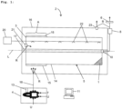
- FIG. 1 A treatment device 2 according to the invention for drying and/or roasting cocoa nib parts 1 is shown in a schematic representation in a partially sectioned side view.
- the treatment device 2 comprises a treatment chamber 3, which is arranged in a housing 16.
- the treatment chamber 3 is mounted on a shaft 17 so as to be rotatable about a longitudinal axis L of the shaft 17.
- the treatment chamber 3 is designed as a drum.
- a heat insulation 15 designed as a double wall is arranged in a section A on an outer wall 14.
- the section A is the area of an outer side 5 of the treatment chamber 3 in which a heated flue gas R is fed to the outer side 5 of the treatment chamber 3.
- the heated flue gas R flows around the treatment chamber 3 and heats it on the outer side 5, heating the outer wall 14 and the cocoa nib parts 1 by conduction.
- the heated flue gas R can then be conveyed out of the housing outlet 23; for this purpose, a valve and/or a pump can be arranged in the housing outlet 23 or in a line connected downstream to it to control and/or regulate the conveyance of the heated flue gas R through the housing outlet 23.
- the treatment chamber 3 has an inlet 21 for the heated flue gas R into the treatment chamber 3 on one end.
- the heated flue gas R is guided through the treatment chamber 3 and conveyed out of the treatment chamber 3 through an outlet 10.
- a volume flow control device 8 is arranged downstream of the treatment chamber 3, which can be a vapor fan, for example.
- the volume flow control device 8 can be used to regulate the volume flow of heated flue gas R through the treatment chamber 3. The regulation takes place in such a way that the maximum speed of the heated flue gas R conveyed through the outlet 10 is less than 20 m/s.
- a lambda probe 6 is arranged in the treatment device 2, by means of which an oxygen content, i.e. an oxygen partial pressure, can be measured.
- the lambda probe 6 is connected to a data processing unit 11.
- Pairs of values for oxygen content and degree of roasting are stored in the data processing unit 11, whereby the moisture content of the cocoa kernel parts 1 can be derived from the degree of roasting.
- a second lambda probe 13 is arranged in a heating device 4 in order to be able to compensate for fluctuations in the oxygen content which can arise through the process of heating the flue gas R.
- the second lambda probe 13 is also connected to the data processing unit 11.
- the heating device 4 comprises the second lambda probe 13 and a furnace which can heat ambient air U to produce heated flue gas R.
- the heated flue gas R is conveyed to the treatment device 2 by means of a supply device 18, which is designed here as a pipeline.
- the treatment device 2 also comprises a loading device 20 for loading the cocoa kernel parts 1 with, for example, water, steam, air or a solution that can be alkaline, for example.
- a line comprising nozzles 22 is connected to the loading device 20 for the corresponding loading of the cocoa kernel parts 1.
- Such a treatment can be carried out, for example, before or after drying and/or roasting the cocoa kernel parts.
- the cocoa nib parts 1 can be fed into the treatment chamber 3 via the outlet 10, through which heated gas can be discharged during operation.
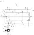
- FIG. 2 An alternative treatment device 2 according to the invention is shown in a schematic representation in a partially sectioned side view.
- the treatment facility shall instruct Figure 3 separate supply channels of the supply device 18 for heated flue gas R and heated clean gas E.
- a fuel T is burned with ambient air U to produce a heated flue gas R.
- the heated flue gas R is conveyed by the supply device 18 directly into the housing 16 to the outside 5 of the treatment chamber 3 in order to heat it.
- a heat exchanger is arranged in the heating device 4 for heating ambient air U to produce heated clean gas E.
- the flue gas is therefore not in fluid communication with the heated clean gas E, so that the flue gas is not conveyed into the treatment chamber 3.
- a volume flow control device 8 is arranged upstream of the heating device 4 to convey the ambient air U into the heating device 4.
- the treatment chamber 3 is designed in such a way that only heated clean gas E can be conveyed into the treatment chamber 3 by means of the feed device 18.
- the treatment chamber 3 has a closed side wall 14 so that the heated flue gas R cannot enter the treatment chamber 3.
- the flue gas R is discharged through the housing outlet 23, whereby here too a suction device for the flue gas R can be arranged downstream of the housing outlet 23, which is not shown here.
- a microwave sensor 7 is arranged in the treatment chamber 3 for measuring the moisture content of the cocoa kernel parts 1. Depending on the measured moisture, the volume flow of heated clean gas E through the treatment chamber 3 is regulated by means of the volume flow control device 8, which is arranged upstream of the treatment chamber 3.
- a mixing device 9 is arranged in the treatment chamber 3 for circulating the cocoa nib parts 1 during the drying and/or roasting of the cocoa nib parts 1. In the illustration shown here, only a part of the mixing device 9 is shown.
- FIG. 3 A further alternative treatment device 2 according to the invention is shown in a schematic representation in a partially sectioned side view.
- the supply of heated clean gas E and heated flue gas R into the housing 16 or the treatment chamber 3 is as in Figure 2 shown trained.
- the treatment facility 2 shall, in accordance with Figure 3 a lambda probe 6 in the treatment chamber 3 for measuring the oxygen content, from which the moisture content of the cocoa kernel parts 1 is determined using the value pairs between oxygen content and degree of roasting stored in the data processing unit 11.
- the heated flue gas R discharged from the housing 16 is fed back to the heating device 4 by means of a return device 12.
- the volume flow control device 8 is arranged for controlling the volume flow of heated clean gas E through the treatment chamber 3 based on the determined moisture content of the cocoa nib parts 1.
- the heated flue gas R is conveyed to a mixing device 19 in which it is possible to set which portion of the flue gas R is returned to the heating device 4 and which portion is conveyed from the treatment device 2.
- the mixing device 19 is connected to the data processing unit 11 in order to control and/or regulate the amount of flue gas R returned to the heating device 4.
- a treatment chamber 3 according to the invention is shown in a partially sectioned side view.
- the mixing mechanism 9 is only shown schematically.
- Figure 5 is a section along the plane AA according to Figure 4
- the sectional view shows a part of the mixing mechanism 9 and the thermal insulation 15, which is arranged as a wall on the outer wall 14 to form a double wall on the outside 5 of the treatment chamber 3.
- the “convective” process step means passing heated gas through the treatment chamber.
- the “conductive” process step means heating the outside of the treatment chamber with a heated gas.
- the temperatures indicated are the temperatures measured in the heating device.
- the target value is the moisture and/or temperature of the food to be achieved.
- Example 1 Reduction of the roasting time by removing the moisture from the cocoa nibs using convection.
- the passage of the heated gas through the treatment chamber is switched off once the final moisture content of 6% by weight is reached.
- the outside of the treatment chamber is then heated conductively until the temperature of the food is 135 °C.
- Example 2 Preventing the oiling of cocoa nibs. Process step Temperature [°C] Target size Convective 250-300 Final moisture of 6% Conductive 680-750 conductive heating for 5 to 20 min Convective 250-300 Final moisture of 3% Conductive 680-750 Final moisture less than 1.8%
- Example 3 Intense flavour development with reduced roasting time. Process step Temperature [°C] Target size Convective 250-300 Final moisture of 4% Conductive 680-750 115 to 125 °C Conductive 580 conductive heating for 5 to 15 minutes
- Example 4 Smoothing the flavor profile to avoid overly intense roasted aromas.
- Example 5 Creating stronger roasted notes in the roasted cocoa nibs. Process step Temperature [°C] Target size Conductive 680-750 105 to 115°C Convective 250-300 Convective heating for 10 min or final humidity less than 1%
- Example 6 Alternative process for roasting untreated cocoa nibs to achieve a roasted aroma similar to that achieved by roasting whole beans.
- Process step Temperature [°C] Target size Convective 250-300 115 to 125 °C or final humidity less than 1%
- FIG. 6 shows a schematic representation of an alternative treatment device 2 according to the invention, each with two hot gas inlet openings 24 and hot gas outlet openings 23.
- the hot gas inlet openings 24 are designed as burner flaps, the hot gas outlet openings 23 as exhaust air flaps.
- the flap position can be changed in a process in various ways, as explained below with some examples.
- Example 7 The product is dried using conductive heating. This is done with a large amount of energy input. For this purpose, both burner flaps 24 and both exhaust flaps 23 are open.
- a control variable for example moisture or oxygen content
- a predetermined target value for example moisture or oxygen content
- hot gas is gently flowed around the treatment chamber 3, for example diagonally, with only one burner flap 24 and an exhaust air flap 23 diagonally opposite being open.
- Example 8 The product is dried using convective and conductive heating. A burner flap 24 and a diagonally opposite exhaust flap 23 are open.
- Example 9 The product is dried using conductive heating. This is done with a large amount of energy input. For this purpose, both burner flaps 24 and both exhaust flaps 23 are open.
- the process switches to roasting. To do this, hot gas is gently flowed around the treatment chamber 3, for example diagonally, with only one burner flap 24 and an exhaust air flap 23 diagonally opposite being open. If the fine particle discharge nevertheless reaches a critical value again, the vapor extraction can be reduced.
- Figure 7 shows a partially sectioned side view of a treatment chamber 3 according to the invention with gas guide elements 25.
- the gas guide elements 25 are attached in the form of guide plates on the outside 14 of the treatment chamber 3.
- the gaps 26 between the gas guide plates 25 ensure that the hot gas flows around the treatment chamber 3 in a meandering path.
- the residence time of the hot gas in the treatment chamber 3 is longer than with a direct path of the gas between burner flaps and exhaust air flaps (not shown here).
- Figure 8 shows a measurement curve 27 of a microwave sensor 7 during a process for drying and/or roasting a food product, wherein the measurement signal is plotted against time.
- the general decreasing course of the measurement curve 27 reflects the decreasing humidity in the treatment chamber 3.
- moisture is introduced into the treatment chamber 3 by the application device 20. Based on a peak 28 in the measurement curve 27, it can be immediately recognized that the moisture actually arrives in the treatment chamber 3 and based on the area under the peak 28, the amount of moisture introduced can be determined.
- the process can be terminated at a time t3.
Landscapes
- Life Sciences & Earth Sciences (AREA)
- Chemical & Material Sciences (AREA)
- Engineering & Computer Science (AREA)
- Food Science & Technology (AREA)
- Polymers & Plastics (AREA)
- Apparatuses For Bulk Treatment Of Fruits And Vegetables And Apparatuses For Preparing Feeds (AREA)
Claims (10)
- Dispositif de traitement (2) pour sécher et/ou torréfier un produit alimentaire, en particulier des fèves de cacao et/ou des éclats de fèves de cacao (1), ledit dispositif de traitement (2) comprenant un carter (16),un compartiment de traitement (3) disposé à l'intérieur du carter (16), le compartiment de traitement (3) étant notamment réalisé sous forme de tambour, et au moins un dispositif de chauffage (4) pour chauffer un gaz, caractériséen ce qu'au moins un capteur, en particulier un capteur d'humidité, est disposé sur et/ou dans le compartiment de traitement (3) pour déterminer une grandeur de contrôle, en particulier l'humidité du produit alimentaire dans le compartiment de traitement (3), pendant le séchage et/ou la torréfaction,de manière à permettre une régulation du séchage et/ou de la torréfaction en fonction de la grandeur de contrôle, en particulier de l'humidité déterminée, eten ce que le dispositif de traitement (2) présente un dispositif de guidage, en particulier réglable, au moyen duquel le gaz chauffé peut être conduit sur différents trajets dans le carter (16), ledit dispositif de guidage comprenant des éléments de guidage présentés à l'extérieur du compartiment de traitement (3), lesdits éléments de guidage pouvant être en particulier des tôles de guidage ou des lamelles prévues sur le côté extérieur du compartiment de traitement (3), ou des canaux de gaz passant autour du compartiment de traitement (3),le compartiment de traitement (3) étant enveloppé de gaz chauffé par les éléments de guidage.
- Dispositif de traitement (2) selon la revendication 1, où la grandeur de contrôle est l'humidité du produit alimentaire ou de la surface du produit alimentaire, une teneur en oxygène, une quantité de matière alimentaire évacuée du compartiment de traitement ou des combinaisons de celles-ci, et/ou où un capteur d'humidité est disposé sur et/ou dans le compartiment de traitement (3), lequel est réalisé comme capteur micro-ondes (7), et/ou au moins deux sondes lambda (6, 13) sont présentes dans le dispositif de traitement (2), la deuxième sonde (13) des deux sondes lambda étant montée contre et/ou dans le dispositif de chauffage (4) pour la mesure de la teneur en oxygène dans le dispositif de chauffage (4).
- Dispositif de traitement (2) selon la revendication 1 ou la revendication 2, où le carter présente au moins deux ouvertures d'alimentation en gaz chaud obturables et/ou au moins deux ouvertures d'évacuation de gaz chaud obturables.
- Dispositif de traitement (2) selon l'une des revendications 1 à 3, où le capteur est réalisé est réalisé comme sonde lambda (6) pour la mesure de la teneur en oxygène dans le compartiment de traitement (3), le dispositif de traitement (2) comprenant en particulier une unité de traitement des données (11), où sont mémorisés des couples de valeurs de degré de torréfaction et d'humidité du produit alimentaire, le degré de torréfaction étant déterminable au moyen d'une mesure et en particulier de la variation de la teneur en oxygène dans le compartiment de traitement (3), et la détermination de l'humidité du produit alimentaire pouvant être effectuée par mesure et en particulier par variation de la teneur en oxygène dans le compartiment de traitement (3) et par les couples de valeurs mémorisés.
- Dispositif de traitement (2) selon l'une des revendications 1 à 4, où un dispositif de régulation de débit volumique (8) est disposé dans le dispositif de traitement (2) pour le débit volumique de gaz chauffé et/ou du gaz conduit vers le dispositif de chauffage (4), le débit volumique pouvant être régulé en fonction de l'humidité déterminée.
- Dispositif de traitement (2) selon l'une des revendications 1 à 5, où le dispositif de guidage est réglable de sorte que le gaz s'écoule de manière régulière autour du compartiment de traitement (3) et qu'une répartition homogène de la chaleur soit ainsi obtenue.
- Dispositif de traitement (2) selon l'une des revendications 1 à 5, où le dispositif de guidage est réglable de manière à ce que le gaz ne s'écoule que sur des parties du compartiment de traitement (3) et qu'une répartition inhomogène de la chaleur soit ainsi obtenue.
- Dispositif de traitement (2) selon la revendication 7, comprenant en outre un dispositif de transfert du produit alimentaire de zones plus froides vers des zones plus chaudes du compartiment de traitement (3) et inversement, par exemple au moyen d'une vis sans fin, d'éléments d'agitation ou de distribution de préférence montés axialement, ou de tôles de guidage.
- Procédé de séchage et/ou de torréfaction d'un produit alimentaire, en particulier de fèves de cacao et/ou d'éclats de fèves de cacao (1), dans un dispositif de traitement (2) selon l'une des revendications précédentes, comprenant un carter (16), un compartiment de traitement (3), au moins un dispositif de chauffage (4) et un dispositif de guidage, en particulier réglable, au moyen duquel le gaz chauffé peut être conduit sur différents trajets dans le carter (16), ledit procédé comprenant les étapes suivantes :- chauffage d'un premier gaz, en particulier d'air pur, au moyen du dispositif de chauffage (4),- chauffage, en particulier par conduction d'une partie du gaz chauffé ou de la totalité de celui-ci, d'un côté extérieur (5) du compartiment de traitement (3),- passage de gaz chauffé, en particulier d'une partie du premier gaz chauffé ou de la totalité de celui-ci, par le compartiment de traitement (3), le passage par le compartiment de traitement (3) pouvant être effectué avant chauffage, après chauffage ou simultanément au chauffage du côté extérieur (5), et- séchage et/ou torréfaction du produit alimentaire dans le compartiment de traitement (3), par chauffage et/ou au moyen du gaz chauffé passant,caractérisé en ce qu'un capteur, en particulier un capteur d'humidité, est disposé contre et/ou dans le compartiment de traitement (3), une détermination d'une grandeur de contrôle, en particulier de l'humidité du produit alimentaire, dans le compartiment de traitement (3) pendant le séchage et/ou la torréfaction, est effectuée sur la base d'une valeur de mesure, en particulier du capteur d'humidité, et une régulation du chauffage et/ou du passage de gaz chauffé est effectuée en fonction de la grandeur de contrôle déterminée, en particulier de l'humidité.
- Procédé selon la revendication 9, où un dispositif de guidage est disposé de sorte qu'une répartition de chaleur non homogène est obtenue dans le compartiment de traitement (3), ledit procédé comprenant en outre l'étape de transport du produit alimentaire à l'intérieur du compartiment de traitement (3) depuis des zones plus froides vers des zones plus chaudes et inversement.
Applications Claiming Priority (3)
| Application Number | Priority Date | Filing Date | Title |
|---|---|---|---|
| EP13152759 | 2013-01-25 | ||
| EP14701525.9A EP2947998B1 (fr) | 2013-01-25 | 2014-01-24 | Procédé et dispositif destinés au séchage et/ou à la torréfaction d'un aliment |
| PCT/EP2014/051394 WO2014114744A2 (fr) | 2013-01-25 | 2014-01-24 | Procédé et dispositif pour sécher et/ou torréfier un aliment |
Related Parent Applications (1)
| Application Number | Title | Priority Date | Filing Date |
|---|---|---|---|
| EP14701525.9A Division EP2947998B1 (fr) | 2013-01-25 | 2014-01-24 | Procédé et dispositif destinés au séchage et/ou à la torréfaction d'un aliment |
Publications (3)
| Publication Number | Publication Date |
|---|---|
| EP3207806A1 EP3207806A1 (fr) | 2017-08-23 |
| EP3207806B1 true EP3207806B1 (fr) | 2024-09-18 |
| EP3207806B8 EP3207806B8 (fr) | 2024-10-23 |
Family
ID=47681701
Family Applications (2)
| Application Number | Title | Priority Date | Filing Date |
|---|---|---|---|
| EP14701525.9A Active EP2947998B1 (fr) | 2013-01-25 | 2014-01-24 | Procédé et dispositif destinés au séchage et/ou à la torréfaction d'un aliment |
| EP17160818.5A Active EP3207806B8 (fr) | 2013-01-25 | 2014-01-24 | Procédé et dispositif destinés au séchage et/ou au grillage d'un aliment |
Family Applications Before (1)
| Application Number | Title | Priority Date | Filing Date |
|---|---|---|---|
| EP14701525.9A Active EP2947998B1 (fr) | 2013-01-25 | 2014-01-24 | Procédé et dispositif destinés au séchage et/ou à la torréfaction d'un aliment |
Country Status (7)
| Country | Link |
|---|---|
| US (1) | US20150351421A1 (fr) |
| EP (2) | EP2947998B1 (fr) |
| AP (1) | AP2015008659A0 (fr) |
| DE (1) | DE202014010598U1 (fr) |
| MY (2) | MY206741A (fr) |
| SG (1) | SG11201505716PA (fr) |
| WO (1) | WO2014114744A2 (fr) |
Families Citing this family (10)
| Publication number | Priority date | Publication date | Assignee | Title |
|---|---|---|---|---|
| US10517422B2 (en) | 2014-11-25 | 2019-12-31 | Koninklijke Philips N.V. | Coffee roasting apparatus, coffee brewing apparatus and coffee roasting method |
| CN105852169A (zh) * | 2016-04-12 | 2016-08-17 | 天津市真如果食品工业有限公司 | 一种干燥果蔬片的便捷布料装置 |
| BR102017011135A2 (pt) * | 2017-05-26 | 2018-12-18 | Jaf Inox Indústria De Máquinas De Chocolates S.A. | equipamento para beneficiamento de amêndoa |
| DE102017222737A1 (de) * | 2017-12-14 | 2019-06-19 | Bühler Barth Gmbh | Wärmebehandlung von stückigen Lebensmitteln |
| CN108936754A (zh) * | 2018-07-27 | 2018-12-07 | 安徽鸡笼山食品有限公司 | 一种蔬菜风干机及其使用方法 |
| CN110881673A (zh) * | 2019-12-16 | 2020-03-17 | 贵州剑荣菌业有限公司 | 菌类专用除湿烘干机 |
| DE102020126276B3 (de) | 2020-10-07 | 2021-11-04 | Hamburg Dresdner Maschinenfabriken Verwaltungsgesellschaft Mbh | Behandlungsanordnung zum Trocknen und/oder Rösten eines Lebensmittels |
| US12484602B2 (en) * | 2021-06-01 | 2025-12-02 | Nature Nate's Llc | Continuous flow popper |
| EP4159051A3 (fr) * | 2021-09-29 | 2023-07-19 | Stronghold Technology, Inc. | Appareil de torréfaction et son procédé de commande |
| DOU2025000293U (es) * | 2023-05-24 | 2026-01-30 | Ayban Carlos Garcia Polanco | Fermentador giratorio automatizado de cacao |
Family Cites Families (67)
| Publication number | Priority date | Publication date | Assignee | Title |
|---|---|---|---|---|
| US2159027A (en) * | 1936-08-20 | 1939-05-23 | Jalma | Process and apparatus for roasting |
| US2443620A (en) * | 1944-06-24 | 1948-06-22 | Alaska Pacific Salmon Company | Process for heat-treating materials |
| US2464421A (en) * | 1948-11-22 | 1949-03-15 | August S Torres | Roasting method |
| US3203341A (en) * | 1960-07-11 | 1965-08-31 | Wood B Hedgepeth | Continuous cooking devices |
| CH398458A (de) * | 1961-10-17 | 1966-03-15 | Basf Ag | Einrichtung zur fortlaufenden Trocknung von pulverförmigen oder gekörnten Stoffen in einem Hochfrequenzfeld |
| FR1473109A (fr) * | 1965-01-15 | 1967-03-17 | Hupp Corp | Procédé et installation pour la torréfaction du café et pour des applications analogues |
| US3384071A (en) * | 1965-02-12 | 1968-05-21 | Robertshaw Controls Co | Cooking apparatus |
| US3345181A (en) * | 1966-01-24 | 1967-10-03 | Hupp Corp | Method for roasting coffee beans and similar particulate solids |
| US3626838A (en) * | 1969-11-24 | 1971-12-14 | Dorran Electronics Inc | Continuous microwave grain cooker |
| BE766056A (fr) * | 1970-05-13 | 1971-10-21 | Nestle Sa | Appareil pour le chauffage de produits granules |
| US3889009A (en) * | 1972-07-31 | 1975-06-10 | Samuel P Lipoma | Method for continuous electromagnetic sterilization of food in a pressure zone |
| US3983356A (en) * | 1974-04-30 | 1976-09-28 | Gerling Moore Inc. | End load for microwave ovens |
| US3916137A (en) * | 1974-05-20 | 1975-10-28 | Gerling Moore Inc | Multi-mode microwave cavity feed system |
| US4180718A (en) * | 1976-09-10 | 1979-12-25 | Lester Hanson | Apparatus and system for processing oil shale |
| US4129768A (en) * | 1977-01-07 | 1978-12-12 | Gerling Moore, Inc. | Method and apparatus for microwave heating of flowable material |
| US4326114A (en) * | 1978-12-11 | 1982-04-20 | Gerling-Moore, Inc. | Apparatus for microwave roasting of coffee beans |
| DE3019622A1 (de) * | 1980-05-22 | 1981-11-26 | SIEMENS AG AAAAA, 1000 Berlin und 8000 München | Verfahren zum betrieb einer vergasungsbrenner/heizkesselanlage |
| US5134263A (en) * | 1983-08-15 | 1992-07-28 | Donald P. Smith | Infrared heating control |
| DD221632A1 (de) * | 1983-12-22 | 1985-05-02 | Nagema Veb K | Verfahren und vorrichtung zum kontinuierlichen herstellen von geroesteter kakaomasse |
| CA1220529A (fr) * | 1984-02-07 | 1987-04-14 | Matsushita Electric Industrial Co., Ltd. | Appareil automatique de chauffage a haute frequence |
| DE3511766A1 (de) * | 1985-03-30 | 1986-10-16 | Hugo Petersen Gesellschaft für verfahrenstechnischen Anlagenbau mbH & Co KG, 6200 Wiesbaden | Verfahren zur desorption eines mit schadstoffen beladenen adsorptionsmittels und anlage zur durchfuehrung des verfahrens |
| CH665754A5 (fr) * | 1985-10-21 | 1988-06-15 | Nestle Sa | Procede et dispositif pour regler le degre de torrefaction d'un produit notamment du cafe. |
| US4913041A (en) * | 1987-11-05 | 1990-04-03 | The Frymaster Corporation | Deep fat frying apparatus |
| IT1213742B (it) * | 1987-12-04 | 1989-12-29 | Vittoria Spa Off | Tostatura di prodotti alimentari circuito di controllo e regolazione quali caffe', frutta secca e simili dei valori dei flussi di aria calda all'interno di impianti per la |
| US5033449A (en) * | 1989-04-13 | 1991-07-23 | The Thermos Company, Inc. | Electronic grill control |
| US5062066A (en) * | 1989-08-17 | 1991-10-29 | Nabisco Brands, Inc. | Model referenced control of a food treatment device |
| IT1244734B (it) * | 1991-02-13 | 1994-08-08 | Francesco Crolla | Procedimento per la cottura rapida di paste alimentari filamentari e simili ed apparecchiatura per la sua realizzazione |
| US5247874A (en) * | 1992-05-20 | 1993-09-28 | Gas Research Institute | High-volume cooking |
| US5269072A (en) * | 1992-05-22 | 1993-12-14 | Felknor International | Coffee roaster |
| US5402713A (en) * | 1993-08-03 | 1995-04-04 | Henny Penny Corporation | Gas fired deep fat fryer |
| US5394623A (en) * | 1993-10-12 | 1995-03-07 | Sewell; Richard C. | Fluidized bed coffee roaster |
| EP0773735B1 (fr) * | 1994-08-01 | 2000-02-16 | Hakvoort Horeca B.V. | Appareil a frire |
| IT1267582B1 (it) * | 1994-09-09 | 1997-02-07 | Zanussi Grandi Impianti Spa | Forno dotato di dispositivo perfezionato di misura dell'umidita' |
| KR960024041A (ko) * | 1994-12-14 | 1996-07-20 | 구자홍 | 조리기의 자동 조리 제어장치 및 그 방법 |
| US5577438A (en) * | 1996-04-02 | 1996-11-26 | G. S. Blodgett Corporation | Gas fired deep fat fryer |
| CA2179125C (fr) * | 1996-06-14 | 2001-01-09 | Ibrahim S. Balbaa | Appareil rotatif a micro-ondes pour chauffage en continu |
| US5749288A (en) * | 1996-09-20 | 1998-05-12 | Skaling; Tim | Device for home roasting of coffee beans |
| US6095037A (en) * | 1996-09-27 | 2000-08-01 | Pitco Frialator, Inc. | High efficient convection fryer with continuous filtration |
| US6084226A (en) * | 1998-04-21 | 2000-07-04 | Cem Corporation | Use of continuously variable power in microwave assisted chemistry |
| DE19824172A1 (de) * | 1998-05-29 | 1999-12-09 | Rational Gmbh | Gargerät mit Energiespeicher- und Energieentnahmesystem |
| DE19835186A1 (de) * | 1998-08-04 | 2000-02-10 | Buehler Ag | Verfahren zur Reinigung eines Gasstromes |
| US5887509A (en) * | 1998-10-01 | 1999-03-30 | Keating Of Chicago, Inc. | Deep fat fryer |
| US6322831B1 (en) * | 1999-04-07 | 2001-11-27 | Henny Penny Corporation | Basket lifting apparatus, basket lifting hinge, and basket lifting control method |
| US6263830B1 (en) * | 1999-04-12 | 2001-07-24 | Matrix Integrated Systems, Inc. | Microwave choke for remote plasma generator |
| US6173506B1 (en) * | 1999-04-29 | 2001-01-16 | Premark Wb Holdings, Inc. | Roaster |
| JP4250311B2 (ja) * | 2000-06-20 | 2009-04-08 | パロマ工業株式会社 | フライヤー |
| US7838799B2 (en) * | 2001-01-12 | 2010-11-23 | Jeffrey Freedman | Coffee roaster method and control |
| US7823626B2 (en) * | 2001-10-15 | 2010-11-02 | Whirlpool Corporation | Refrigerated oven |
| US7794765B2 (en) * | 2002-01-25 | 2010-09-14 | James Edward Maguire | Method and apparatus for cooking low fat french fries |
| US9351495B2 (en) * | 2002-07-05 | 2016-05-31 | Turbochef Technologies, Inc. | Air fryer |
| ITMI20021793A1 (it) * | 2002-08-06 | 2004-02-07 | Landi Renzo Spa | Sistema di alimentazione e controllo perfezionato di un motore a combustione interna alimentato da due diversi combustibili |
| US20070267409A1 (en) * | 2002-10-16 | 2007-11-22 | Coffee Technologies International Inc. | Assembled container for roasting food |
| AU2003288146A1 (en) * | 2002-11-22 | 2004-06-18 | Basell Polyolefine Gmbh | Safe removal of volatile, oxidizable compounds from particles, in particular polymer particles |
| US7375309B2 (en) * | 2005-12-28 | 2008-05-20 | Ag-Way Technologies, Llc | Method and apparatus using microwave energy to heat a target |
| DE102006004669A1 (de) * | 2006-01-31 | 2007-08-09 | Uhde Gmbh | Koksofen mit optimierter Steuerung und Verfahren zur Steuerung |
| US20100187339A1 (en) * | 2006-02-07 | 2010-07-29 | David Kannar | Method for processing material to produce particles of a desired size |
| US20080063768A1 (en) * | 2006-09-11 | 2008-03-13 | Vasuhi Rasanayagam | Quick chilling of fry oil under modified atmosphere |
| KR100887985B1 (ko) * | 2006-10-13 | 2009-03-09 | 송유진 | 커피 볶음기 및 그 제어방법 |
| CA2676993C (fr) * | 2007-02-05 | 2013-07-09 | Pioneer Hi-Bred International, Inc. | Appareil et procede de presentation d'un echantillon particulaire au champ de balayage d'un dispositif de capteur |
| WO2009127728A2 (fr) | 2008-04-18 | 2009-10-22 | Probat-Werke Von Gimborn Maschinenfabrik Gmbh | Procédé et dispositif de traitement de noix de cacao et de morceaux de noix de cacao |
| DE202008011577U1 (de) * | 2008-08-27 | 2008-10-30 | BEAR Mühlen & Behälter GmbH | Trommelröster |
| IT1393389B1 (it) * | 2008-10-24 | 2012-04-20 | Bar System Europ Srl | Apparecchiatura per la tostatura di chicchi di caffe' e semi commestibili in genere |
| US8361282B2 (en) * | 2009-08-13 | 2013-01-29 | Tekgar, Llc | System and method using a microwave-transparent reaction chamber for production of fuel from a carbon-containing feedstock |
| US8839714B2 (en) * | 2009-08-28 | 2014-09-23 | The Middleby Corporation | Apparatus and method for controlling a conveyor oven |
| FR2956307B3 (fr) * | 2010-02-17 | 2012-10-05 | Sara Lee/De N V | Systeme pour boisson au cafe, appareil de preparation de cafe, cartouche d'emballage pour grains de cafe et procede de preparation de cafe |
| US8759727B2 (en) * | 2010-08-09 | 2014-06-24 | Coffee Technologies, International, Inc. | Microwave oven for roasting low moisture foods |
| US9386798B2 (en) * | 2012-02-10 | 2016-07-12 | Gourmet Coffee Roasters Inc. | Fluidized bed coffee roaster |
-
2014
- 2014-01-24 WO PCT/EP2014/051394 patent/WO2014114744A2/fr not_active Ceased
- 2014-01-24 US US14/760,729 patent/US20150351421A1/en not_active Abandoned
- 2014-01-24 AP AP2015008659A patent/AP2015008659A0/xx unknown
- 2014-01-24 MY MYPI2021000394A patent/MY206741A/en unknown
- 2014-01-24 EP EP14701525.9A patent/EP2947998B1/fr active Active
- 2014-01-24 EP EP17160818.5A patent/EP3207806B8/fr active Active
- 2014-01-24 MY MYPI2015702267A patent/MY183264A/en unknown
- 2014-01-24 DE DE202014010598.7U patent/DE202014010598U1/de not_active Expired - Lifetime
- 2014-01-24 SG SG11201505716PA patent/SG11201505716PA/en unknown
Also Published As
| Publication number | Publication date |
|---|---|
| US20150351421A1 (en) | 2015-12-10 |
| MY183264A (en) | 2021-02-18 |
| EP3207806A1 (fr) | 2017-08-23 |
| WO2014114744A2 (fr) | 2014-07-31 |
| DE202014010598U1 (de) | 2016-02-02 |
| AP2015008659A0 (en) | 2015-08-31 |
| EP2947998B1 (fr) | 2017-04-05 |
| EP3207806B8 (fr) | 2024-10-23 |
| SG11201505716PA (en) | 2015-09-29 |
| EP2947998A2 (fr) | 2015-12-02 |
| MY206741A (en) | 2025-01-03 |
| WO2014114744A3 (fr) | 2014-12-18 |
Similar Documents
| Publication | Publication Date | Title |
|---|---|---|
| EP3207806B1 (fr) | Procédé et dispositif destinés au séchage et/ou au grillage d'un aliment | |
| EP0981278B1 (fr) | Dispositif et procede de cuisson au four | |
| DE2531390C2 (de) | Vorrichtung zum Rösten von Kaffeebohnen und Verfahren zur Ermittlung der Geschmacksrichtung von mit der Vorrichtung gerösteten Kaffeebohnen | |
| DE3546129C2 (de) | Verfahren zum Trocknen eines Feststoffes | |
| DE68926696T2 (de) | Behandlungsvorrichtung für körniges Material | |
| EP3437476B1 (fr) | Appareil de cuisson et procédé d'utilisation d'un appareil de cuisson | |
| DE68911244T2 (de) | Kaffeebohnenröster. | |
| DE102009028913A1 (de) | Vorrichtung und Verfahren zum Behandeln von Tabak | |
| EP0113900A1 (fr) | Appareil et procédé pour le traitement de nourriture au moyen de micro-ondes | |
| DE3504950C2 (fr) | ||
| WO2009015651A1 (fr) | Procédé pour la conduite économe en énergie d'un processus de traitement d'aliments ou d'un processus de nettoyage d'une chambre de traitement et appareil de cuisson correspondant | |
| CH671142A5 (fr) | ||
| DE102021000618B4 (de) | Verfahren zur Regelung eines Trocknungsverlaufes eines Produktes in einem Trockner | |
| EP1855058B1 (fr) | Procédé et appareil de cuisson de plats à la vapeur | |
| EP3498110B1 (fr) | Traitement thermique des produits alimentaires en morceaux | |
| DE102010050440A1 (de) | Trocknungsverfahren und Trocknungsvorrichtung | |
| DE102017107164A1 (de) | Verfahren zum Steuern des Garprozesses in Lebensmittelöfen | |
| WO2019154912A1 (fr) | Dispositif de traitement continu d'aliments solides pour humains et d'aliments solides pour animaux et d'autres produits en vrac, muni d'un dispositif de traitement thermique pour réaliser un traitement thermique continu | |
| EP3679808B1 (fr) | Dispositif destiné à griller des semences | |
| EP2220970B2 (fr) | Préparation d'un produit de cuisson avec détection de la vitesse de refroidissement | |
| DE102021122600B3 (de) | Trocknungsvorrichtung und Verfahren zur Ausbildung einer Beschichtung in einem Hohlraum einer metallischen Dose | |
| DE102018102702B3 (de) | Konditionierungsvorrichtung zur Durchlaufbehandlung von festen Lebens- und Futtermitteln und anderen Schüttgütern nach einer Wärmebehandlung | |
| DE10221254A1 (de) | Verfahren und Vorrichtung zum Entfeuchten von Lebensmitteln | |
| WO2019048411A1 (fr) | Conditionnement du tabac | |
| DE3529202C1 (de) | Hopfendarre |
Legal Events
| Date | Code | Title | Description |
|---|---|---|---|
| PUAI | Public reference made under article 153(3) epc to a published international application that has entered the european phase |
Free format text: ORIGINAL CODE: 0009012 |
|
| STAA | Information on the status of an ep patent application or granted ep patent |
Free format text: STATUS: THE APPLICATION HAS BEEN PUBLISHED |
|
| AC | Divisional application: reference to earlier application |
Ref document number: 2947998 Country of ref document: EP Kind code of ref document: P |
|
| AK | Designated contracting states |
Kind code of ref document: A1 Designated state(s): AL AT BE BG CH CY CZ DE DK EE ES FI FR GB GR HR HU IE IS IT LI LT LU LV MC MK MT NL NO PL PT RO RS SE SI SK SM TR |
|
| STAA | Information on the status of an ep patent application or granted ep patent |
Free format text: STATUS: REQUEST FOR EXAMINATION WAS MADE |
|
| 17P | Request for examination filed |
Effective date: 20180104 |
|
| RBV | Designated contracting states (corrected) |
Designated state(s): AL AT BE BG CH CY CZ DE DK EE ES FI FR GB GR HR HU IE IS IT LI LT LU LV MC MK MT NL NO PL PT RO RS SE SI SK SM TR |
|
| STAA | Information on the status of an ep patent application or granted ep patent |
Free format text: STATUS: EXAMINATION IS IN PROGRESS |
|
| 17Q | First examination report despatched |
Effective date: 20181026 |
|
| P01 | Opt-out of the competence of the unified patent court (upc) registered |
Effective date: 20230523 |
|
| GRAP | Despatch of communication of intention to grant a patent |
Free format text: ORIGINAL CODE: EPIDOSNIGR1 |
|
| STAA | Information on the status of an ep patent application or granted ep patent |
Free format text: STATUS: GRANT OF PATENT IS INTENDED |
|
| INTG | Intention to grant announced |
Effective date: 20240624 |
|
| GRAS | Grant fee paid |
Free format text: ORIGINAL CODE: EPIDOSNIGR3 |
|
| GRAA | (expected) grant |
Free format text: ORIGINAL CODE: 0009210 |
|
| STAA | Information on the status of an ep patent application or granted ep patent |
Free format text: STATUS: THE PATENT HAS BEEN GRANTED |
|
| AC | Divisional application: reference to earlier application |
Ref document number: 2947998 Country of ref document: EP Kind code of ref document: P |
|
| AK | Designated contracting states |
Kind code of ref document: B1 Designated state(s): AL AT BE BG CH CY CZ DE DK EE ES FI FR GB GR HR HU IE IS IT LI LT LU LV MC MK MT NL NO PL PT RO RS SE SI SK SM TR |
|
| REG | Reference to a national code |
Ref country code: GB Ref legal event code: FG4D Free format text: NOT ENGLISH |
|
| REG | Reference to a national code |
Ref country code: CH Ref legal event code: PK Free format text: BERICHTIGUNG B8 Ref country code: CH Ref legal event code: EP |
|
| REG | Reference to a national code |
Ref country code: DE Ref legal event code: R081 Ref document number: 502014016873 Country of ref document: DE Owner name: BUEHLER AG, CH Free format text: FORMER OWNER: ANMELDERANGABEN UNKLAR / UNVOLLSTAENDIG, 80297 MUENCHEN, DE |
|
| REG | Reference to a national code |
Ref country code: IE Ref legal event code: FG4D Free format text: LANGUAGE OF EP DOCUMENT: GERMAN |
|
| REG | Reference to a national code |
Ref country code: DE Ref legal event code: R096 Ref document number: 502014016873 Country of ref document: DE |
|
| RAP2 | Party data changed (patent owner data changed or rights of a patent transferred) |
Owner name: BUEHLER AG |
|
| REG | Reference to a national code |
Ref country code: NL Ref legal event code: FP |
|
| REG | Reference to a national code |
Ref country code: LT Ref legal event code: MG9D |
|
| PG25 | Lapsed in a contracting state [announced via postgrant information from national office to epo] |
Ref country code: NO Free format text: LAPSE BECAUSE OF FAILURE TO SUBMIT A TRANSLATION OF THE DESCRIPTION OR TO PAY THE FEE WITHIN THE PRESCRIBED TIME-LIMIT Effective date: 20241218 |
|
| PG25 | Lapsed in a contracting state [announced via postgrant information from national office to epo] |
Ref country code: GR Free format text: LAPSE BECAUSE OF FAILURE TO SUBMIT A TRANSLATION OF THE DESCRIPTION OR TO PAY THE FEE WITHIN THE PRESCRIBED TIME-LIMIT Effective date: 20241219 Ref country code: FI Free format text: LAPSE BECAUSE OF FAILURE TO SUBMIT A TRANSLATION OF THE DESCRIPTION OR TO PAY THE FEE WITHIN THE PRESCRIBED TIME-LIMIT Effective date: 20240918 |
|
| PG25 | Lapsed in a contracting state [announced via postgrant information from national office to epo] |
Ref country code: BG Free format text: LAPSE BECAUSE OF FAILURE TO SUBMIT A TRANSLATION OF THE DESCRIPTION OR TO PAY THE FEE WITHIN THE PRESCRIBED TIME-LIMIT Effective date: 20240918 |
|
| PG25 | Lapsed in a contracting state [announced via postgrant information from national office to epo] |
Ref country code: LV Free format text: LAPSE BECAUSE OF FAILURE TO SUBMIT A TRANSLATION OF THE DESCRIPTION OR TO PAY THE FEE WITHIN THE PRESCRIBED TIME-LIMIT Effective date: 20240918 |
|
| PG25 | Lapsed in a contracting state [announced via postgrant information from national office to epo] |
Ref country code: HR Free format text: LAPSE BECAUSE OF FAILURE TO SUBMIT A TRANSLATION OF THE DESCRIPTION OR TO PAY THE FEE WITHIN THE PRESCRIBED TIME-LIMIT Effective date: 20240918 |
|
| PG25 | Lapsed in a contracting state [announced via postgrant information from national office to epo] |
Ref country code: RS Free format text: LAPSE BECAUSE OF FAILURE TO SUBMIT A TRANSLATION OF THE DESCRIPTION OR TO PAY THE FEE WITHIN THE PRESCRIBED TIME-LIMIT Effective date: 20241218 |
|
| PG25 | Lapsed in a contracting state [announced via postgrant information from national office to epo] |
Ref country code: RS Free format text: LAPSE BECAUSE OF FAILURE TO SUBMIT A TRANSLATION OF THE DESCRIPTION OR TO PAY THE FEE WITHIN THE PRESCRIBED TIME-LIMIT Effective date: 20241218 Ref country code: NO Free format text: LAPSE BECAUSE OF FAILURE TO SUBMIT A TRANSLATION OF THE DESCRIPTION OR TO PAY THE FEE WITHIN THE PRESCRIBED TIME-LIMIT Effective date: 20241218 Ref country code: LV Free format text: LAPSE BECAUSE OF FAILURE TO SUBMIT A TRANSLATION OF THE DESCRIPTION OR TO PAY THE FEE WITHIN THE PRESCRIBED TIME-LIMIT Effective date: 20240918 Ref country code: HR Free format text: LAPSE BECAUSE OF FAILURE TO SUBMIT A TRANSLATION OF THE DESCRIPTION OR TO PAY THE FEE WITHIN THE PRESCRIBED TIME-LIMIT Effective date: 20240918 Ref country code: GR Free format text: LAPSE BECAUSE OF FAILURE TO SUBMIT A TRANSLATION OF THE DESCRIPTION OR TO PAY THE FEE WITHIN THE PRESCRIBED TIME-LIMIT Effective date: 20241219 Ref country code: FI Free format text: LAPSE BECAUSE OF FAILURE TO SUBMIT A TRANSLATION OF THE DESCRIPTION OR TO PAY THE FEE WITHIN THE PRESCRIBED TIME-LIMIT Effective date: 20240918 Ref country code: BG Free format text: LAPSE BECAUSE OF FAILURE TO SUBMIT A TRANSLATION OF THE DESCRIPTION OR TO PAY THE FEE WITHIN THE PRESCRIBED TIME-LIMIT Effective date: 20240918 |
|
| PG25 | Lapsed in a contracting state [announced via postgrant information from national office to epo] |
Ref country code: IS Free format text: LAPSE BECAUSE OF FAILURE TO SUBMIT A TRANSLATION OF THE DESCRIPTION OR TO PAY THE FEE WITHIN THE PRESCRIBED TIME-LIMIT Effective date: 20250118 Ref country code: PT Free format text: LAPSE BECAUSE OF FAILURE TO SUBMIT A TRANSLATION OF THE DESCRIPTION OR TO PAY THE FEE WITHIN THE PRESCRIBED TIME-LIMIT Effective date: 20250120 |
|
| PG25 | Lapsed in a contracting state [announced via postgrant information from national office to epo] |
Ref country code: RO Free format text: LAPSE BECAUSE OF FAILURE TO SUBMIT A TRANSLATION OF THE DESCRIPTION OR TO PAY THE FEE WITHIN THE PRESCRIBED TIME-LIMIT Effective date: 20240918 Ref country code: SM Free format text: LAPSE BECAUSE OF FAILURE TO SUBMIT A TRANSLATION OF THE DESCRIPTION OR TO PAY THE FEE WITHIN THE PRESCRIBED TIME-LIMIT Effective date: 20240918 |
|
| PG25 | Lapsed in a contracting state [announced via postgrant information from national office to epo] |
Ref country code: ES Free format text: LAPSE BECAUSE OF FAILURE TO SUBMIT A TRANSLATION OF THE DESCRIPTION OR TO PAY THE FEE WITHIN THE PRESCRIBED TIME-LIMIT Effective date: 20240918 |
|
| PG25 | Lapsed in a contracting state [announced via postgrant information from national office to epo] |
Ref country code: CZ Free format text: LAPSE BECAUSE OF FAILURE TO SUBMIT A TRANSLATION OF THE DESCRIPTION OR TO PAY THE FEE WITHIN THE PRESCRIBED TIME-LIMIT Effective date: 20240918 Ref country code: PL Free format text: LAPSE BECAUSE OF FAILURE TO SUBMIT A TRANSLATION OF THE DESCRIPTION OR TO PAY THE FEE WITHIN THE PRESCRIBED TIME-LIMIT Effective date: 20240918 |
|
| PG25 | Lapsed in a contracting state [announced via postgrant information from national office to epo] |
Ref country code: SK Free format text: LAPSE BECAUSE OF FAILURE TO SUBMIT A TRANSLATION OF THE DESCRIPTION OR TO PAY THE FEE WITHIN THE PRESCRIBED TIME-LIMIT Effective date: 20240918 |
|
| REG | Reference to a national code |
Ref country code: DE Ref legal event code: R097 Ref document number: 502014016873 Country of ref document: DE |
|
| PG25 | Lapsed in a contracting state [announced via postgrant information from national office to epo] |
Ref country code: DK Free format text: LAPSE BECAUSE OF FAILURE TO SUBMIT A TRANSLATION OF THE DESCRIPTION OR TO PAY THE FEE WITHIN THE PRESCRIBED TIME-LIMIT Effective date: 20240918 |
|
| PLBE | No opposition filed within time limit |
Free format text: ORIGINAL CODE: 0009261 |
|
| STAA | Information on the status of an ep patent application or granted ep patent |
Free format text: STATUS: NO OPPOSITION FILED WITHIN TIME LIMIT |
|
| 26N | No opposition filed |
Effective date: 20250619 |
|
| PG25 | Lapsed in a contracting state [announced via postgrant information from national office to epo] |
Ref country code: SE Free format text: LAPSE BECAUSE OF FAILURE TO SUBMIT A TRANSLATION OF THE DESCRIPTION OR TO PAY THE FEE WITHIN THE PRESCRIBED TIME-LIMIT Effective date: 20240918 |
|
| PG25 | Lapsed in a contracting state [announced via postgrant information from national office to epo] |
Ref country code: MC Free format text: LAPSE BECAUSE OF FAILURE TO SUBMIT A TRANSLATION OF THE DESCRIPTION OR TO PAY THE FEE WITHIN THE PRESCRIBED TIME-LIMIT Effective date: 20240918 Ref country code: LU Free format text: LAPSE BECAUSE OF NON-PAYMENT OF DUE FEES Effective date: 20250124 |
|
| GBPC | Gb: european patent ceased through non-payment of renewal fee |
Effective date: 20250124 |
|
| PG25 | Lapsed in a contracting state [announced via postgrant information from national office to epo] |
Ref country code: GB Free format text: LAPSE BECAUSE OF NON-PAYMENT OF DUE FEES Effective date: 20250124 Ref country code: BE Free format text: LAPSE BECAUSE OF NON-PAYMENT OF DUE FEES Effective date: 20250131 |
|
| REG | Reference to a national code |
Ref country code: BE Ref legal event code: MM Effective date: 20250131 |
|
| PG25 | Lapsed in a contracting state [announced via postgrant information from national office to epo] |
Ref country code: IE Free format text: LAPSE BECAUSE OF NON-PAYMENT OF DUE FEES Effective date: 20250124 |
|
| REG | Reference to a national code |
Ref country code: CH Ref legal event code: U11 Free format text: ST27 STATUS EVENT CODE: U-0-0-U10-U11 (AS PROVIDED BY THE NATIONAL OFFICE) Effective date: 20260201 |
|
| PGFP | Annual fee paid to national office [announced via postgrant information from national office to epo] |
Ref country code: NL Payment date: 20260121 Year of fee payment: 13 |
|
| REG | Reference to a national code |
Ref country code: AT Ref legal event code: MM01 Ref document number: 1723889 Country of ref document: AT Kind code of ref document: T Effective date: 20250124 |
|
| PGFP | Annual fee paid to national office [announced via postgrant information from national office to epo] |
Ref country code: DE Payment date: 20260120 Year of fee payment: 13 |
|
| PG25 | Lapsed in a contracting state [announced via postgrant information from national office to epo] |
Ref country code: AT Free format text: LAPSE BECAUSE OF NON-PAYMENT OF DUE FEES Effective date: 20250124 |
|
| PGFP | Annual fee paid to national office [announced via postgrant information from national office to epo] |
Ref country code: IT Payment date: 20260130 Year of fee payment: 13 |
|
| PGFP | Annual fee paid to national office [announced via postgrant information from national office to epo] |
Ref country code: FR Payment date: 20260123 Year of fee payment: 13 |
|
| PGFP | Annual fee paid to national office [announced via postgrant information from national office to epo] |
Ref country code: CH Payment date: 20260201 Year of fee payment: 13 |