EP3207848A1 - Grundplatte für einen saugkopf für staubsauger oder dergleichen - Google Patents
Grundplatte für einen saugkopf für staubsauger oder dergleichen Download PDFInfo
- Publication number
- EP3207848A1 EP3207848A1 EP17156210.1A EP17156210A EP3207848A1 EP 3207848 A1 EP3207848 A1 EP 3207848A1 EP 17156210 A EP17156210 A EP 17156210A EP 3207848 A1 EP3207848 A1 EP 3207848A1
- Authority
- EP
- European Patent Office
- Prior art keywords
- base plate
- channel
- lower face
- same plane
- plate channel
- Prior art date
- Legal status (The legal status is an assumption and is not a legal conclusion. Google has not performed a legal analysis and makes no representation as to the accuracy of the status listed.)
- Granted
Links
Images


Classifications
-
- A—HUMAN NECESSITIES
- A47—FURNITURE; DOMESTIC ARTICLES OR APPLIANCES; COFFEE MILLS; SPICE MILLS; SUCTION CLEANERS IN GENERAL
- A47L—DOMESTIC WASHING OR CLEANING; SUCTION CLEANERS IN GENERAL
- A47L9/00—Details or accessories of suction cleaners, e.g. mechanical means for controlling the suction or for effecting pulsating action; Storing devices specially adapted to suction cleaners or parts thereof; Carrying-vehicles specially adapted for suction cleaners
- A47L9/02—Nozzles
-
- A—HUMAN NECESSITIES
- A47—FURNITURE; DOMESTIC ARTICLES OR APPLIANCES; COFFEE MILLS; SPICE MILLS; SUCTION CLEANERS IN GENERAL
- A47L—DOMESTIC WASHING OR CLEANING; SUCTION CLEANERS IN GENERAL
- A47L7/00—Suction cleaners adapted for additional purposes; Tables with suction openings for cleaning purposes; Containers for cleaning articles by suction; Suction cleaners adapted to cleaning of brushes; Suction cleaners adapted to taking-up liquids
- A47L7/0004—Suction cleaners adapted to take up liquids, e.g. wet or dry vacuum cleaners
- A47L7/0009—Suction cleaners adapted to take up liquids, e.g. wet or dry vacuum cleaners with means mounted on the nozzle; nozzles specially adapted for the recovery of liquid
Definitions
- the present invention relates to the sector of electric household appliances for performing cleaning by means of suction, such as a vacuum cleaner, an electric broom or a multi-purpose drum vacuum cleaner, for sucking up dust and/or fluids and/or dirt from a surface. More particularly, it relates to a base plate for a suction head to be fitted to such an electric household appliance.
- a vacuum cleaner, an electric broom or a similar electric household appliance for performing cleaning by means of suction comprises a suction head for sucking up dust, dirt or fluids from a surface.
- a suction head is generally referred to by the term "brush”.
- the terms “suction head” and “brush” are considered to be equivalent.
- the term “vacuum cleaner” will be used with a broad meaning so as to include all those apparatus, for professional or domestic use, which perform cleaning by means of suction. Therefore, the term “vacuum cleaner” will comprise a vacuum cleaner, an electric broom, a so-called multi-purpose drum vacuum cleaner, a centralized suction system for domestic or industrial use and an apparatus for supplying and sucking in steam.
- a known suction head comprises a base plate shaped so as to have at least one base plate channel open towards a surface to be vacuumed, a suction channel which, during use, is joined to the base plate and is in fluid communication with the base plate channel and optionally a covering body which can be connected to the base plate/suction channel assembly.
- the other end of the suction channel communicates with a suction tube usually via a rotatable joint.
- suction heads in which the suction channel, during use, is joined to the covering body.
- GB 2 496 663 A discloses a cleaner head for a vacuum cleaner.
- WO 2005/096907 A1 discloses a surface cleaning apparatus.
- US 2014/033473 A1 discloses a floor tool for a vacuum cleaning apparatus.
- GB 2 471 918 A discloses a surface treating head.
- the Applicant has defined the object of improving substantially the suction efficiency of a conventional suction head on carpets, rugs, doormats, matting or the like,
- the Applicant has defined the object of providing a base plate shaped so as to provide an improved suction performance compared to the suction heads provided with a known suction plate, the suction power remaining the same.
- the aforementioned object may be achieved with a suction head able to reduce suction losses caused by poor adherence between the base plate and the surface to be vacuumed.
- a base plate for a vacuum cleaner comprising a lower face configured so as to be directed towards the surface to be vacuumed, an opposite upper face and a base plate channel open towards the surface to be vacuumed, wherein the base plate channel comprises a front edge and a rear edge, wherein said lower face consists of a single surface delimited by a perimeter comprising a front side, a rear side and two lateral sides, said single surface being completely closed except said base plate channel which is the sole aperture configured to suck up dust and/or fluids and/or dirt from said surface to be sucked, wherein said base plate, during use, is joined to a suction channel and said base plate channel is in fluid communication with the suction channel, wherein said base plate channel extends substantially through a whole width of said base plate and has closed ends in proximity of lateral sides of said base plate, wherein at least the surface of the lower face which extends along the whole front edge of the base plate channel and at least the surface of the lower face which extends along
- a suction head comprising a base plate with a base plate channel open towards a surface to be vacuumed, a suction channel in fluid communication with the base plate channel and a covering body connected to at least one of said base plate and said suction channel, wherein the base plate has a lower face configured so as to be directed towards the surface to be vacuumed, and an opposite upper face, wherein the base plate channel comprises a front edge and a rear edge, wherein said lower face consists of a single surface delimited by a perimeter comprising a front side, a rear side and two lateral sides, said single surface being completely closed except said base plate channel which is the sole aperture configured to suck up dust and/or fluids and/or dirt from said surface to be sucked, wherein said base plate channel extends substantially through a whole width of said base plate and has closed ends in proximity of lateral sides of said base plate, wherein at least the surface of the lower face which extends along the whole front edge of the base plate channel and at least
- At least one further surface of the lower face not in the vicinity of the rear edge of the base plate channel lies in said same plane.
- At least one further surface of the lower face not in the vicinity of the front edge of the base plate channel lies in said same plane.
- substantially the whole of the lower face is flat and lies in said same plane.
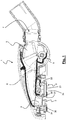
- Figure 1 shows by way of example an embodiment of a suction head 1 of a vacuum cleaner or the like with a base plate 2 mounted in accordance with an embodiment of the present invention.
- the suction head 1 according to the invention is particularly suitable for vacuuming surfaces such as carpets, rugs, doormats, matting or the like. It is, however, also effective for smooth and compact surfaces such as floors made of stone (marble or the like), terracotta, clinker, cement, resin, tiles, parquet or the like, in particular when used together with bristles which may vary their configuration depending on the needs.
- the base plate has a lower face 21 directed towards the surface to be vacuumed and an opposite upper face 22 which is connected to the brush body 8 or to other components of the suction head.
- the suction head 1 has a suction channel 4 which, during use, is joined to the base plate 2 and is in fluid communication with a base plate channel 3 and optionally a covering body which can be connected to the base plate and/or to the suction channel.
- the other end of the suction channel 3 communicates with a suction tube, usually via a rotatable joint 7.
- the base plate of a known suction head has an inclined front surface departing from the front edge of the base plate channel and extending towards the front edge of the base plate.
- a known base plate also has an inclined rear surface departing from the rear edge of the base plate channel and extending towards the rear edge of the base plate. Therefore the surface of a known base plate is not flat. Therefore, the imprint of a known base plate does not coincide with the surface of the base plate.
- a further drawback of the known base plates is the impossibility of correctly employing the strips of velvet.
- the strips of velvet usually there are two strips of velvet, a front strip of velvet along the central part of the front inclined surface and a rear strip of velvet along the central part of the rear inclined surface. It can be easily understood that, in order to work properly, the two strips must be parallel to the surface to be vacuumed.
- the front strip of velvet works correctly only when its whole area rests on the ground and therefore the suction head is inclined so that the front inclined surface is parallel to the surface to be vacuumed. In all the other situations, the front velvet strip works partially or not all.
- the base plate has a completely flat surface 21.
- the entire surface of the lower face 21 of the base plate lies in a single plane.
- This embodiment is shown in Figures 2.1 to 2.4 .
- the front surface 34 and the rear surface 36 lie in a same plane, i.e. a horizontal plane.
- the expression "the entire surface of the base plate lies in a single plane” is understood as meaning that substantially the entire surface 21 of the base plate 2 lies in a single plane, with allowance for a tolerance of up to a ⁇ 5°, preferably not greater than ⁇ 3° and even more preferably not greater than ⁇ 1°.
- the base plate channel 3, any holes, cavities, depressions or the like must not be taken into consideration during calculation of the surface area. For example, holes for screws designed to connect the base plate to another component of the suction head are not considered.
- Figure 2.2 is a cross-sectional view along the line A-A of Figure 2.1 .
- the planarity between the front surface 34 (that between the front edge of the base plate and the front edge of the channel 3) and the rear surface 35 (that between the rear edge of the base plate and the rear edge of the channel 3) is evident. Also visible are the cavities 36' inside which the strips of velvet 36 are housed and fixed. The bottom of these cavities is substantially parallel to the plane of the surfaces 34 and 35 and therefore the strips of velvet also lie in the same plane as the surfaces 34 (front surface) and 35 (rear surface).
- the strips of velvet could also not lie in the same plane as the surfaces 34 and/or 35.
- Figure 2.3 is another cross-sectional view along the line B-B of Figure 2.1 .
- Figure 2.4 is a cross-sectional view similar to that of Figure 2.2 , but relates to a variant in which the front edge 31 of the channel 3 has a substantially triangular tooth 31 D which helps separate the dust from the surface to be vacuumed.
- the tooth 31D extends towards the inside of the opening of the channel 3.
- the base plate has a completely flat surface in an area which extends along the front edge 31 of the base plate channel 3 and along its rear edge 32.
- a part of the surface of the base plate i.e. that around the edge 31+32 of the base plate channel, lies in a single plane.
- This embodiment is clearly shown in Figures 3.1 and 3.2 . From these figures it is clear that not all the rear surface 35 is at the same level as the front surface 34. Only the portion 35' closer to the rear edge 32 lies in the same plane as the front surface 34. The other portion 35" lies in a plane different from that of the surfaces 34 and 35'.
- the front flat surface 34 extends over the entire width L of the suction head and over a depth of between a few mm (3-6 mm) and 10-50 mm.
- the rear flat surface 35' extends over the entire width of the suction head and over a depth of between a few mm (3-6 mm) and 10-50 mm.
- the base plate has a completely flat surface in an area which extends along the front edge of the base plate channel and along its rear edge. Substantially in the same manner as the second embodiment ( Figures 3.1 and 3.2 ). Moreover, along the remainder of the surface of the base plate there are separate areas 35"' which also lie in the same plane as the flat surface 34, 35' around the front edge 31 and the rear edge 32 of the channel of the base plate. These separate areas 35"' have the function of making the surface of the suction head more stable.
- the separate areas 35"' may extend over the entire width of the suction head or only over a part thereof. They may have a length of between a few mm (3-6 mm) and a few tens of millimetres (10-50 mm).
Landscapes
- Engineering & Computer Science (AREA)
- Mechanical Engineering (AREA)
- Nozzles For Electric Vacuum Cleaners (AREA)
Priority Applications (1)
| Application Number | Priority Date | Filing Date | Title |
|---|---|---|---|
| PL17156210T PL3207848T3 (pl) | 2016-02-19 | 2017-02-15 | Płyta podstawowa do głowicy ssącej do odkurzaczy lub podobnych |
Applications Claiming Priority (1)
| Application Number | Priority Date | Filing Date | Title |
|---|---|---|---|
| ITUB2016A000903A ITUB20160903A1 (it) | 2016-02-19 | 2016-02-19 | Piastra di base per testa di aspirazione per aspirapolvere o simile |
Publications (2)
| Publication Number | Publication Date |
|---|---|
| EP3207848A1 true EP3207848A1 (de) | 2017-08-23 |
| EP3207848B1 EP3207848B1 (de) | 2019-04-03 |
Family
ID=56027031
Family Applications (1)
| Application Number | Title | Priority Date | Filing Date |
|---|---|---|---|
| EP17156210.1A Active EP3207848B1 (de) | 2016-02-19 | 2017-02-15 | Grundplatte für einen saugkopf für staubsauger oder dergleichen |
Country Status (9)
| Country | Link |
|---|---|
| US (1) | US10238254B2 (de) |
| EP (1) | EP3207848B1 (de) |
| CN (1) | CN107095618B (de) |
| DK (1) | DK3207848T3 (de) |
| ES (1) | ES2729340T3 (de) |
| HU (1) | HUE043859T2 (de) |
| IT (1) | ITUB20160903A1 (de) |
| PL (1) | PL3207848T3 (de) |
| TR (1) | TR201908329T4 (de) |
Cited By (5)
| Publication number | Priority date | Publication date | Assignee | Title |
|---|---|---|---|---|
| EP3494852A1 (de) | 2017-12-11 | 2019-06-12 | New Ermes Europe S.r.l. | Grundplatte für einen staubsaugersaugkopf zum absaugen von feinstaub und grobem schmutz |
| USD922014S1 (en) | 2018-09-18 | 2021-06-08 | New Ermes S.r.l. | Accessory for vacuum cleaners |
| USD953673S1 (en) | 2020-02-17 | 2022-05-31 | New Ermes Europe S.R.L. | Head of a vacuum cleaner |
| SE2330398A1 (en) * | 2023-09-12 | 2025-03-13 | Electrolux Ab | Nozzle for a vacuum cleaner and a vacuum cleaner having such a nozzle |
| USD1105672S1 (en) * | 2023-08-30 | 2025-12-09 | Sharkninja Operating Llc | Vacuum cleaner and vacuum nozzle |
Families Citing this family (2)
| Publication number | Priority date | Publication date | Assignee | Title |
|---|---|---|---|---|
| IT202000001555A1 (it) | 2020-01-28 | 2021-07-28 | New Ermes Europe Srl | Dispositivo adattatore per aspirapolvere elettrico senza filo |
| CN116634912A (zh) | 2020-12-23 | 2023-08-22 | 新埃莫斯欧洲有限责任公司 | 电动抽吸头 |
Citations (5)
| Publication number | Priority date | Publication date | Assignee | Title |
|---|---|---|---|---|
| WO2005096907A1 (en) | 2004-04-08 | 2005-10-20 | Grey Technology Limited | Surface cleaning apparatus |
| GB2471918A (en) | 2009-07-16 | 2011-01-19 | Dyson Technology Ltd | A surface treating head |
| GB2496663A (en) | 2011-11-18 | 2013-05-22 | Dyson Technology Ltd | Cleaner head for a vacuum cleaner |
| US20140033473A1 (en) | 2012-08-03 | 2014-02-06 | Dyson Technology Limited | Floor tool for a vacuum cleaning appliance |
| EP2989954A1 (de) * | 2014-08-26 | 2016-03-02 | New Ermes Europe S.r.l. | Zubehör für eine saugdüse eines staubsaugers oder dergleichen |
Family Cites Families (11)
| Publication number | Priority date | Publication date | Assignee | Title |
|---|---|---|---|---|
| GB9603250D0 (en) * | 1996-02-16 | 1996-04-17 | Vax Ltd | Cleaning heads and adaptors for the use therewith |
| DE19906137C1 (de) * | 1999-02-13 | 2000-07-20 | Wessel Werk Gmbh | Gleitsohle für eine Staubsaugerdüse |
| DE10000504C2 (de) * | 2000-01-08 | 2002-11-07 | Wessel Werk Gmbh | Saugkopf für Bodenstaubsauger |
| EP1210898B1 (de) * | 2000-11-22 | 2004-03-24 | Wessel-Werk Gmbh | Staubsaugerdüse für Bodenstaubsauger, insbesondere Haushaltsstaubsauger |
| EP1595485B1 (de) * | 2004-05-10 | 2007-03-28 | Wessel-Werk GmbH & Co. KG | Bodendüse für Staubsauger |
| US8117714B2 (en) * | 2005-03-09 | 2012-02-21 | Bissell Homecare, Inc. | Vacuum cleaner with hair collection element |
| DE202009010089U1 (de) * | 2009-06-18 | 2009-11-12 | Wessel-Werk Gmbh | Bodendüse für Staubsauger |
| CN202161265U (zh) * | 2010-05-21 | 2012-03-14 | 莫菲理查兹有限公司 | 用于真空吸尘器的吸头和该真空吸尘器 |
| CN203195600U (zh) * | 2013-03-26 | 2013-09-18 | 科沃斯机器人科技(苏州)有限公司 | 吸尘器地刷及其吸尘器 |
| GB2530932A (en) * | 2013-11-25 | 2016-04-06 | Hoover Ltd | Vacuum cleaner head |
| DK2944242T3 (da) * | 2014-05-14 | 2019-11-11 | New Ermes Europe Srl | Sugehoved til en støvsuger eller lignende med forbedret basispladekanal |
-
2016
- 2016-02-19 IT ITUB2016A000903A patent/ITUB20160903A1/it unknown
-
2017
- 2017-02-15 ES ES17156210T patent/ES2729340T3/es active Active
- 2017-02-15 PL PL17156210T patent/PL3207848T3/pl unknown
- 2017-02-15 HU HUE17156210A patent/HUE043859T2/hu unknown
- 2017-02-15 TR TR2019/08329T patent/TR201908329T4/tr unknown
- 2017-02-15 DK DK17156210.1T patent/DK3207848T3/da active
- 2017-02-15 EP EP17156210.1A patent/EP3207848B1/de active Active
- 2017-02-17 US US15/435,322 patent/US10238254B2/en active Active
- 2017-02-17 CN CN201710084816.0A patent/CN107095618B/zh active Active
Patent Citations (5)
| Publication number | Priority date | Publication date | Assignee | Title |
|---|---|---|---|---|
| WO2005096907A1 (en) | 2004-04-08 | 2005-10-20 | Grey Technology Limited | Surface cleaning apparatus |
| GB2471918A (en) | 2009-07-16 | 2011-01-19 | Dyson Technology Ltd | A surface treating head |
| GB2496663A (en) | 2011-11-18 | 2013-05-22 | Dyson Technology Ltd | Cleaner head for a vacuum cleaner |
| US20140033473A1 (en) | 2012-08-03 | 2014-02-06 | Dyson Technology Limited | Floor tool for a vacuum cleaning appliance |
| EP2989954A1 (de) * | 2014-08-26 | 2016-03-02 | New Ermes Europe S.r.l. | Zubehör für eine saugdüse eines staubsaugers oder dergleichen |
Cited By (7)
| Publication number | Priority date | Publication date | Assignee | Title |
|---|---|---|---|---|
| EP3494852A1 (de) | 2017-12-11 | 2019-06-12 | New Ermes Europe S.r.l. | Grundplatte für einen staubsaugersaugkopf zum absaugen von feinstaub und grobem schmutz |
| US11224319B2 (en) | 2017-12-11 | 2022-01-18 | New Ermes Europe S.R.L. | Base plate for a vacuum cleaner suction head for the suction of fine dust and large debris |
| USD922014S1 (en) | 2018-09-18 | 2021-06-08 | New Ermes S.r.l. | Accessory for vacuum cleaners |
| USD953673S1 (en) | 2020-02-17 | 2022-05-31 | New Ermes Europe S.R.L. | Head of a vacuum cleaner |
| USD1105672S1 (en) * | 2023-08-30 | 2025-12-09 | Sharkninja Operating Llc | Vacuum cleaner and vacuum nozzle |
| SE2330398A1 (en) * | 2023-09-12 | 2025-03-13 | Electrolux Ab | Nozzle for a vacuum cleaner and a vacuum cleaner having such a nozzle |
| SE547527C2 (en) * | 2023-09-12 | 2025-09-14 | Electrolux Ab | Nozzle for a vacuum cleaner and a vacuum cleaner having such a nozzle |
Also Published As
| Publication number | Publication date |
|---|---|
| ES2729340T3 (es) | 2019-10-31 |
| EP3207848B1 (de) | 2019-04-03 |
| TR201908329T4 (tr) | 2019-06-21 |
| ITUB20160903A1 (it) | 2017-08-19 |
| PL3207848T3 (pl) | 2019-09-30 |
| US10238254B2 (en) | 2019-03-26 |
| DK3207848T3 (da) | 2019-06-24 |
| US20170238774A1 (en) | 2017-08-24 |
| CN107095618B (zh) | 2021-04-13 |
| CN107095618A (zh) | 2017-08-29 |
| HUE043859T2 (hu) | 2019-09-30 |
Similar Documents
| Publication | Publication Date | Title |
|---|---|---|
| EP3207848B1 (de) | Grundplatte für einen saugkopf für staubsauger oder dergleichen | |
| EP3494852B1 (de) | Grundplatte für einen staubsaugersaugkopf zum absaugen von feinstaub und grobem schmutz | |
| EP3510908B1 (de) | Zubehör für einen staubsaugersaugkopf zum sammeln von grossen schmutzpartikeln | |
| CN108289581B (zh) | 用于真空吸尘器的吸头及其操作方法 | |
| EP2995234B1 (de) | Saugdüse für einen staubsauger oder dergleichen mit staubaufwirbelungsvorrichtung | |
| AU2021232679A1 (en) | Cleaning apparatus with combing unit for removing debris from cleaning roller | |
| GB2528145A (en) | Vacuum cleaner head | |
| CN109199230B (zh) | 光滑地面吸尘器吸嘴 | |
| ES2998585T3 (en) | Vacuum cleaner nozzle equipped with a rear scraping rib | |
| EP2989954B1 (de) | Zubehör für eine saugdüse eines staubsaugers oder dergleichen | |
| CN210300848U (zh) | 吸尘器吸嘴以及包括其的家用吸尘器 | |
| HK1236782A1 (en) | Base plate for a suction head for vacuum cleaners or the like | |
| CN210354558U (zh) | 吸尘器吸嘴以及包括这种吸尘器吸嘴的家用吸尘器 | |
| EP3284380A1 (de) | Staubsaugerkopf | |
| CN219206177U (zh) | 一种方便整理缝隙的毛刷 | |
| CN205411082U (zh) | 地刷及吸尘器 | |
| HK40010127A (en) | Base plate for a vacuum cleaner suction head for the suction of fine dust and large debris | |
| HK40010127B (en) | Base plate for a vacuum cleaner suction head for the suction of fine dust and large debris | |
| CN115813268A (zh) | 扫地机器人及地毯清洁方法 | |
| EP3151711B1 (de) | Saugdüse mit drei einstellungen | |
| HK1217625B (en) | Accessory for a suction nozzle of vacuum cleaners or the like | |
| ITUB201648598U1 (it) | Piastra di base per testa di aspirazione per aspirapolvere o simile. | |
| JP2015070960A (ja) | 吸込ヘッド及び電気掃除機 | |
| KR101354675B1 (ko) | 진공청소기의 흡입장치 | |
| ES1303688U (es) | Cabezal universal para aspiradoras |
Legal Events
| Date | Code | Title | Description |
|---|---|---|---|
| PUAI | Public reference made under article 153(3) epc to a published international application that has entered the european phase |
Free format text: ORIGINAL CODE: 0009012 |
|
| STAA | Information on the status of an ep patent application or granted ep patent |
Free format text: STATUS: THE APPLICATION HAS BEEN PUBLISHED |
|
| AK | Designated contracting states |
Kind code of ref document: A1 Designated state(s): AL AT BE BG CH CY CZ DE DK EE ES FI FR GB GR HR HU IE IS IT LI LT LU LV MC MK MT NL NO PL PT RO RS SE SI SK SM TR |
|
| AX | Request for extension of the european patent |
Extension state: BA ME |
|
| STAA | Information on the status of an ep patent application or granted ep patent |
Free format text: STATUS: REQUEST FOR EXAMINATION WAS MADE |
|
| 17P | Request for examination filed |
Effective date: 20180223 |
|
| RBV | Designated contracting states (corrected) |
Designated state(s): AL AT BE BG CH CY CZ DE DK EE ES FI FR GB GR HR HU IE IS IT LI LT LU LV MC MK MT NL NO PL PT RO RS SE SI SK SM TR |
|
| REG | Reference to a national code |
Ref country code: HK Ref legal event code: DE Ref document number: 1236782 Country of ref document: HK |
|
| GRAP | Despatch of communication of intention to grant a patent |
Free format text: ORIGINAL CODE: EPIDOSNIGR1 |
|
| STAA | Information on the status of an ep patent application or granted ep patent |
Free format text: STATUS: GRANT OF PATENT IS INTENDED |
|
| INTG | Intention to grant announced |
Effective date: 20181107 |
|
| GRAS | Grant fee paid |
Free format text: ORIGINAL CODE: EPIDOSNIGR3 |
|
| GRAA | (expected) grant |
Free format text: ORIGINAL CODE: 0009210 |
|
| STAA | Information on the status of an ep patent application or granted ep patent |
Free format text: STATUS: THE PATENT HAS BEEN GRANTED |
|
| AK | Designated contracting states |
Kind code of ref document: B1 Designated state(s): AL AT BE BG CH CY CZ DE DK EE ES FI FR GB GR HR HU IE IS IT LI LT LU LV MC MK MT NL NO PL PT RO RS SE SI SK SM TR |
|
| REG | Reference to a national code |
Ref country code: GB Ref legal event code: FG4D |
|
| REG | Reference to a national code |
Ref country code: CH Ref legal event code: EP Ref country code: AT Ref legal event code: REF Ref document number: 1114703 Country of ref document: AT Kind code of ref document: T Effective date: 20190415 |
|
| REG | Reference to a national code |
Ref country code: DE Ref legal event code: R096 Ref document number: 602017002990 Country of ref document: DE |
|
| REG | Reference to a national code |
Ref country code: CH Ref legal event code: NV Representative=s name: E. BLUM AND CO. AG PATENT- UND MARKENANWAELTE , CH |
|
| REG | Reference to a national code |
Ref country code: IE Ref legal event code: FG4D |
|
| REG | Reference to a national code |
Ref country code: NL Ref legal event code: FP |
|
| REG | Reference to a national code |
Ref country code: SE Ref legal event code: TRGR |
|
| REG | Reference to a national code |
Ref country code: DK Ref legal event code: T3 Effective date: 20190619 |
|
| REG | Reference to a national code |
Ref country code: LT Ref legal event code: MG4D |
|
| REG | Reference to a national code |
Ref country code: AT Ref legal event code: MK05 Ref document number: 1114703 Country of ref document: AT Kind code of ref document: T Effective date: 20190403 |
|
| REG | Reference to a national code |
Ref country code: HU Ref legal event code: AG4A Ref document number: E043859 Country of ref document: HU |
|
| PG25 | Lapsed in a contracting state [announced via postgrant information from national office to epo] |
Ref country code: AL Free format text: LAPSE BECAUSE OF FAILURE TO SUBMIT A TRANSLATION OF THE DESCRIPTION OR TO PAY THE FEE WITHIN THE PRESCRIBED TIME-LIMIT Effective date: 20190403 Ref country code: PT Free format text: LAPSE BECAUSE OF FAILURE TO SUBMIT A TRANSLATION OF THE DESCRIPTION OR TO PAY THE FEE WITHIN THE PRESCRIBED TIME-LIMIT Effective date: 20190803 Ref country code: CZ Free format text: LAPSE BECAUSE OF FAILURE TO SUBMIT A TRANSLATION OF THE DESCRIPTION OR TO PAY THE FEE WITHIN THE PRESCRIBED TIME-LIMIT Effective date: 20190403 Ref country code: HR Free format text: LAPSE BECAUSE OF FAILURE TO SUBMIT A TRANSLATION OF THE DESCRIPTION OR TO PAY THE FEE WITHIN THE PRESCRIBED TIME-LIMIT Effective date: 20190403 Ref country code: NO Free format text: LAPSE BECAUSE OF FAILURE TO SUBMIT A TRANSLATION OF THE DESCRIPTION OR TO PAY THE FEE WITHIN THE PRESCRIBED TIME-LIMIT Effective date: 20190703 Ref country code: LT Free format text: LAPSE BECAUSE OF FAILURE TO SUBMIT A TRANSLATION OF THE DESCRIPTION OR TO PAY THE FEE WITHIN THE PRESCRIBED TIME-LIMIT Effective date: 20190403 Ref country code: FI Free format text: LAPSE BECAUSE OF FAILURE TO SUBMIT A TRANSLATION OF THE DESCRIPTION OR TO PAY THE FEE WITHIN THE PRESCRIBED TIME-LIMIT Effective date: 20190403 |
|
| REG | Reference to a national code |
Ref country code: ES Ref legal event code: FG2A Ref document number: 2729340 Country of ref document: ES Kind code of ref document: T3 Effective date: 20191031 |
|
| PG25 | Lapsed in a contracting state [announced via postgrant information from national office to epo] |
Ref country code: LV Free format text: LAPSE BECAUSE OF FAILURE TO SUBMIT A TRANSLATION OF THE DESCRIPTION OR TO PAY THE FEE WITHIN THE PRESCRIBED TIME-LIMIT Effective date: 20190403 Ref country code: BG Free format text: LAPSE BECAUSE OF FAILURE TO SUBMIT A TRANSLATION OF THE DESCRIPTION OR TO PAY THE FEE WITHIN THE PRESCRIBED TIME-LIMIT Effective date: 20190703 Ref country code: RS Free format text: LAPSE BECAUSE OF FAILURE TO SUBMIT A TRANSLATION OF THE DESCRIPTION OR TO PAY THE FEE WITHIN THE PRESCRIBED TIME-LIMIT Effective date: 20190403 Ref country code: GR Free format text: LAPSE BECAUSE OF FAILURE TO SUBMIT A TRANSLATION OF THE DESCRIPTION OR TO PAY THE FEE WITHIN THE PRESCRIBED TIME-LIMIT Effective date: 20190704 |
|
| PG25 | Lapsed in a contracting state [announced via postgrant information from national office to epo] |
Ref country code: IS Free format text: LAPSE BECAUSE OF FAILURE TO SUBMIT A TRANSLATION OF THE DESCRIPTION OR TO PAY THE FEE WITHIN THE PRESCRIBED TIME-LIMIT Effective date: 20190803 Ref country code: AT Free format text: LAPSE BECAUSE OF FAILURE TO SUBMIT A TRANSLATION OF THE DESCRIPTION OR TO PAY THE FEE WITHIN THE PRESCRIBED TIME-LIMIT Effective date: 20190403 |
|
| REG | Reference to a national code |
Ref country code: DE Ref legal event code: R097 Ref document number: 602017002990 Country of ref document: DE |
|
| PG25 | Lapsed in a contracting state [announced via postgrant information from national office to epo] |
Ref country code: SK Free format text: LAPSE BECAUSE OF FAILURE TO SUBMIT A TRANSLATION OF THE DESCRIPTION OR TO PAY THE FEE WITHIN THE PRESCRIBED TIME-LIMIT Effective date: 20190403 Ref country code: EE Free format text: LAPSE BECAUSE OF FAILURE TO SUBMIT A TRANSLATION OF THE DESCRIPTION OR TO PAY THE FEE WITHIN THE PRESCRIBED TIME-LIMIT Effective date: 20190403 Ref country code: RO Free format text: LAPSE BECAUSE OF FAILURE TO SUBMIT A TRANSLATION OF THE DESCRIPTION OR TO PAY THE FEE WITHIN THE PRESCRIBED TIME-LIMIT Effective date: 20190403 |
|
| PLBE | No opposition filed within time limit |
Free format text: ORIGINAL CODE: 0009261 |
|
| STAA | Information on the status of an ep patent application or granted ep patent |
Free format text: STATUS: NO OPPOSITION FILED WITHIN TIME LIMIT |
|
| PG25 | Lapsed in a contracting state [announced via postgrant information from national office to epo] |
Ref country code: SM Free format text: LAPSE BECAUSE OF FAILURE TO SUBMIT A TRANSLATION OF THE DESCRIPTION OR TO PAY THE FEE WITHIN THE PRESCRIBED TIME-LIMIT Effective date: 20190403 |
|
| 26N | No opposition filed |
Effective date: 20200106 |
|
| PG25 | Lapsed in a contracting state [announced via postgrant information from national office to epo] |
Ref country code: SI Free format text: LAPSE BECAUSE OF FAILURE TO SUBMIT A TRANSLATION OF THE DESCRIPTION OR TO PAY THE FEE WITHIN THE PRESCRIBED TIME-LIMIT Effective date: 20190403 |
|
| PG25 | Lapsed in a contracting state [announced via postgrant information from national office to epo] |
Ref country code: MC Free format text: LAPSE BECAUSE OF FAILURE TO SUBMIT A TRANSLATION OF THE DESCRIPTION OR TO PAY THE FEE WITHIN THE PRESCRIBED TIME-LIMIT Effective date: 20190403 Ref country code: LU Free format text: LAPSE BECAUSE OF NON-PAYMENT OF DUE FEES Effective date: 20200215 |
|
| PG25 | Lapsed in a contracting state [announced via postgrant information from national office to epo] |
Ref country code: IE Free format text: LAPSE BECAUSE OF NON-PAYMENT OF DUE FEES Effective date: 20200215 |
|
| PG25 | Lapsed in a contracting state [announced via postgrant information from national office to epo] |
Ref country code: MT Free format text: LAPSE BECAUSE OF FAILURE TO SUBMIT A TRANSLATION OF THE DESCRIPTION OR TO PAY THE FEE WITHIN THE PRESCRIBED TIME-LIMIT Effective date: 20190403 Ref country code: CY Free format text: LAPSE BECAUSE OF FAILURE TO SUBMIT A TRANSLATION OF THE DESCRIPTION OR TO PAY THE FEE WITHIN THE PRESCRIBED TIME-LIMIT Effective date: 20190403 |
|
| PG25 | Lapsed in a contracting state [announced via postgrant information from national office to epo] |
Ref country code: MK Free format text: LAPSE BECAUSE OF FAILURE TO SUBMIT A TRANSLATION OF THE DESCRIPTION OR TO PAY THE FEE WITHIN THE PRESCRIBED TIME-LIMIT Effective date: 20190403 |
|
| P01 | Opt-out of the competence of the unified patent court (upc) registered |
Effective date: 20230529 |
|
| REG | Reference to a national code |
Ref country code: HK Ref legal event code: WD Ref document number: 1236782 Country of ref document: HK |
|
| PGFP | Annual fee paid to national office [announced via postgrant information from national office to epo] |
Ref country code: ES Payment date: 20250331 Year of fee payment: 9 |
|
| REG | Reference to a national code |
Ref country code: CH Ref legal event code: U11 Free format text: ST27 STATUS EVENT CODE: U-0-0-U10-U11 (AS PROVIDED BY THE NATIONAL OFFICE) Effective date: 20260301 |
|
| PGFP | Annual fee paid to national office [announced via postgrant information from national office to epo] |
Ref country code: NL Payment date: 20260218 Year of fee payment: 10 |
|
| PGFP | Annual fee paid to national office [announced via postgrant information from national office to epo] |
Ref country code: HU Payment date: 20260220 Year of fee payment: 10 |
|
| PGFP | Annual fee paid to national office [announced via postgrant information from national office to epo] |
Ref country code: SE Payment date: 20260218 Year of fee payment: 10 |
|
| PGFP | Annual fee paid to national office [announced via postgrant information from national office to epo] |
Ref country code: GB Payment date: 20260219 Year of fee payment: 10 |
|
| PGFP | Annual fee paid to national office [announced via postgrant information from national office to epo] |
Ref country code: DE Payment date: 20260218 Year of fee payment: 10 Ref country code: DK Payment date: 20260220 Year of fee payment: 10 |
|
| PGFP | Annual fee paid to national office [announced via postgrant information from national office to epo] |
Ref country code: BE Payment date: 20260218 Year of fee payment: 10 Ref country code: IT Payment date: 20260216 Year of fee payment: 10 |
|
| PGFP | Annual fee paid to national office [announced via postgrant information from national office to epo] |
Ref country code: FR Payment date: 20260218 Year of fee payment: 10 |
|
| PGFP | Annual fee paid to national office [announced via postgrant information from national office to epo] |
Ref country code: TR Payment date: 20260209 Year of fee payment: 10 |
|
| PGFP | Annual fee paid to national office [announced via postgrant information from national office to epo] |
Ref country code: CH Payment date: 20260301 Year of fee payment: 10 |
|
| PGFP | Annual fee paid to national office [announced via postgrant information from national office to epo] |
Ref country code: PL Payment date: 20260127 Year of fee payment: 10 |