EP3207909B1 - Structure de support - Google Patents
Structure de support Download PDFInfo
- Publication number
- EP3207909B1 EP3207909B1 EP16305189.9A EP16305189A EP3207909B1 EP 3207909 B1 EP3207909 B1 EP 3207909B1 EP 16305189 A EP16305189 A EP 16305189A EP 3207909 B1 EP3207909 B1 EP 3207909B1
- Authority
- EP
- European Patent Office
- Prior art keywords
- leg
- supporting structure
- load
- receiving part
- legs
- Prior art date
- Legal status (The legal status is an assumption and is not a legal conclusion. Google has not performed a legal analysis and makes no representation as to the accuracy of the status listed.)
- Active
Links
Images


Classifications
-
- A—HUMAN NECESSITIES
- A61—MEDICAL OR VETERINARY SCIENCE; HYGIENE
- A61G—TRANSPORT, PERSONAL CONVEYANCES, OR ACCOMMODATION SPECIALLY ADAPTED FOR PATIENTS OR DISABLED PERSONS; OPERATING TABLES OR CHAIRS; CHAIRS FOR DENTISTRY; FUNERAL DEVICES
- A61G5/00—Chairs or personal conveyances specially adapted for patients or disabled persons, e.g. wheelchairs
- A61G5/04—Chairs or personal conveyances specially adapted for patients or disabled persons, e.g. wheelchairs motor-driven
-
- A—HUMAN NECESSITIES
- A61—MEDICAL OR VETERINARY SCIENCE; HYGIENE
- A61G—TRANSPORT, PERSONAL CONVEYANCES, OR ACCOMMODATION SPECIALLY ADAPTED FOR PATIENTS OR DISABLED PERSONS; OPERATING TABLES OR CHAIRS; CHAIRS FOR DENTISTRY; FUNERAL DEVICES
- A61G5/00—Chairs or personal conveyances specially adapted for patients or disabled persons, e.g. wheelchairs
- A61G5/06—Chairs or personal conveyances specially adapted for patients or disabled persons, e.g. wheelchairs with obstacle mounting facilities, e.g. for climbing stairs, kerbs or steps
- A61G5/061—Chairs or personal conveyances specially adapted for patients or disabled persons, e.g. wheelchairs with obstacle mounting facilities, e.g. for climbing stairs, kerbs or steps for climbing stairs
-
- A—HUMAN NECESSITIES
- A61—MEDICAL OR VETERINARY SCIENCE; HYGIENE
- A61G—TRANSPORT, PERSONAL CONVEYANCES, OR ACCOMMODATION SPECIALLY ADAPTED FOR PATIENTS OR DISABLED PERSONS; OPERATING TABLES OR CHAIRS; CHAIRS FOR DENTISTRY; FUNERAL DEVICES
- A61G5/00—Chairs or personal conveyances specially adapted for patients or disabled persons, e.g. wheelchairs
- A61G5/06—Chairs or personal conveyances specially adapted for patients or disabled persons, e.g. wheelchairs with obstacle mounting facilities, e.g. for climbing stairs, kerbs or steps
- A61G5/068—Chairs or personal conveyances specially adapted for patients or disabled persons, e.g. wheelchairs with obstacle mounting facilities, e.g. for climbing stairs, kerbs or steps with extensible supports pushing upwards, e.g. telescopic legs
-
- A—HUMAN NECESSITIES
- A61—MEDICAL OR VETERINARY SCIENCE; HYGIENE
- A61G—TRANSPORT, PERSONAL CONVEYANCES, OR ACCOMMODATION SPECIALLY ADAPTED FOR PATIENTS OR DISABLED PERSONS; OPERATING TABLES OR CHAIRS; CHAIRS FOR DENTISTRY; FUNERAL DEVICES
- A61G5/00—Chairs or personal conveyances specially adapted for patients or disabled persons, e.g. wheelchairs
- A61G5/10—Parts, details or accessories
- A61G5/12—Rests specially adapted therefor, e.g. for the head or the feet
- A61G5/122—Rests specially adapted therefor, e.g. for the head or the feet for the back
-
- A—HUMAN NECESSITIES
- A61—MEDICAL OR VETERINARY SCIENCE; HYGIENE
- A61G—TRANSPORT, PERSONAL CONVEYANCES, OR ACCOMMODATION SPECIALLY ADAPTED FOR PATIENTS OR DISABLED PERSONS; OPERATING TABLES OR CHAIRS; CHAIRS FOR DENTISTRY; FUNERAL DEVICES
- A61G5/00—Chairs or personal conveyances specially adapted for patients or disabled persons, e.g. wheelchairs
- A61G5/10—Parts, details or accessories
- A61G5/12—Rests specially adapted therefor, e.g. for the head or the feet
- A61G5/124—Rests specially adapted therefor, e.g. for the head or the feet for pelvis or buttocks
-
- A—HUMAN NECESSITIES
- A61—MEDICAL OR VETERINARY SCIENCE; HYGIENE
- A61G—TRANSPORT, PERSONAL CONVEYANCES, OR ACCOMMODATION SPECIALLY ADAPTED FOR PATIENTS OR DISABLED PERSONS; OPERATING TABLES OR CHAIRS; CHAIRS FOR DENTISTRY; FUNERAL DEVICES
- A61G5/00—Chairs or personal conveyances specially adapted for patients or disabled persons, e.g. wheelchairs
- A61G5/10—Parts, details or accessories
- A61G5/12—Rests specially adapted therefor, e.g. for the head or the feet
- A61G5/127—Rests specially adapted therefor, e.g. for the head or the feet for lower legs
-
- A—HUMAN NECESSITIES
- A61—MEDICAL OR VETERINARY SCIENCE; HYGIENE
- A61G—TRANSPORT, PERSONAL CONVEYANCES, OR ACCOMMODATION SPECIALLY ADAPTED FOR PATIENTS OR DISABLED PERSONS; OPERATING TABLES OR CHAIRS; CHAIRS FOR DENTISTRY; FUNERAL DEVICES
- A61G5/00—Chairs or personal conveyances specially adapted for patients or disabled persons, e.g. wheelchairs
- A61G5/10—Parts, details or accessories
- A61G5/12—Rests specially adapted therefor, e.g. for the head or the feet
- A61G5/128—Rests specially adapted therefor, e.g. for the head or the feet for feet
-
- A—HUMAN NECESSITIES
- A61—MEDICAL OR VETERINARY SCIENCE; HYGIENE
- A61G—TRANSPORT, PERSONAL CONVEYANCES, OR ACCOMMODATION SPECIALLY ADAPTED FOR PATIENTS OR DISABLED PERSONS; OPERATING TABLES OR CHAIRS; CHAIRS FOR DENTISTRY; FUNERAL DEVICES
- A61G5/00—Chairs or personal conveyances specially adapted for patients or disabled persons, e.g. wheelchairs
- A61G5/10—Parts, details or accessories
- A61G5/14—Standing-up or sitting-down aids
-
- A—HUMAN NECESSITIES
- A61—MEDICAL OR VETERINARY SCIENCE; HYGIENE
- A61H—PHYSICAL THERAPY APPARATUS, e.g. DEVICES FOR LOCATING OR STIMULATING REFLEX POINTS IN THE BODY; ARTIFICIAL RESPIRATION; MASSAGE; BATHING DEVICES FOR SPECIAL THERAPEUTIC OR HYGIENIC PURPOSES OR SPECIFIC PARTS OF THE BODY
- A61H1/00—Apparatus for passive exercising; Vibrating apparatus; Chiropractic devices, e.g. body impacting devices, external devices for briefly extending or aligning unbroken bones
- A61H1/02—Stretching or bending or torsioning apparatus for exercising
- A61H1/0237—Stretching or bending or torsioning apparatus for exercising for the lower limbs
- A61H1/024—Knee
-
- A—HUMAN NECESSITIES
- A61—MEDICAL OR VETERINARY SCIENCE; HYGIENE
- A61H—PHYSICAL THERAPY APPARATUS, e.g. DEVICES FOR LOCATING OR STIMULATING REFLEX POINTS IN THE BODY; ARTIFICIAL RESPIRATION; MASSAGE; BATHING DEVICES FOR SPECIAL THERAPEUTIC OR HYGIENIC PURPOSES OR SPECIFIC PARTS OF THE BODY
- A61H1/00—Apparatus for passive exercising; Vibrating apparatus; Chiropractic devices, e.g. body impacting devices, external devices for briefly extending or aligning unbroken bones
- A61H1/02—Stretching or bending or torsioning apparatus for exercising
- A61H1/0237—Stretching or bending or torsioning apparatus for exercising for the lower limbs
- A61H1/0244—Hip
-
- A—HUMAN NECESSITIES
- A61—MEDICAL OR VETERINARY SCIENCE; HYGIENE
- A61H—PHYSICAL THERAPY APPARATUS, e.g. DEVICES FOR LOCATING OR STIMULATING REFLEX POINTS IN THE BODY; ARTIFICIAL RESPIRATION; MASSAGE; BATHING DEVICES FOR SPECIAL THERAPEUTIC OR HYGIENIC PURPOSES OR SPECIFIC PARTS OF THE BODY
- A61H1/00—Apparatus for passive exercising; Vibrating apparatus; Chiropractic devices, e.g. body impacting devices, external devices for briefly extending or aligning unbroken bones
- A61H1/02—Stretching or bending or torsioning apparatus for exercising
- A61H1/0237—Stretching or bending or torsioning apparatus for exercising for the lower limbs
- A61H1/0266—Foot
-
- A—HUMAN NECESSITIES
- A61—MEDICAL OR VETERINARY SCIENCE; HYGIENE
- A61H—PHYSICAL THERAPY APPARATUS, e.g. DEVICES FOR LOCATING OR STIMULATING REFLEX POINTS IN THE BODY; ARTIFICIAL RESPIRATION; MASSAGE; BATHING DEVICES FOR SPECIAL THERAPEUTIC OR HYGIENIC PURPOSES OR SPECIFIC PARTS OF THE BODY
- A61H3/00—Appliances for aiding patients or disabled persons to walk about
- A61H3/008—Appliances for aiding patients or disabled persons to walk about using suspension devices for supporting the body in an upright walking or standing position, e.g. harnesses
-
- A—HUMAN NECESSITIES
- A61—MEDICAL OR VETERINARY SCIENCE; HYGIENE
- A61H—PHYSICAL THERAPY APPARATUS, e.g. DEVICES FOR LOCATING OR STIMULATING REFLEX POINTS IN THE BODY; ARTIFICIAL RESPIRATION; MASSAGE; BATHING DEVICES FOR SPECIAL THERAPEUTIC OR HYGIENIC PURPOSES OR SPECIFIC PARTS OF THE BODY
- A61H3/00—Appliances for aiding patients or disabled persons to walk about
- A61H3/04—Wheeled walking aids for patients or disabled persons
-
- A—HUMAN NECESSITIES
- A61—MEDICAL OR VETERINARY SCIENCE; HYGIENE
- A61H—PHYSICAL THERAPY APPARATUS, e.g. DEVICES FOR LOCATING OR STIMULATING REFLEX POINTS IN THE BODY; ARTIFICIAL RESPIRATION; MASSAGE; BATHING DEVICES FOR SPECIAL THERAPEUTIC OR HYGIENIC PURPOSES OR SPECIFIC PARTS OF THE BODY
- A61H3/00—Appliances for aiding patients or disabled persons to walk about
- A61H2003/001—Appliances for aiding patients or disabled persons to walk about on steps or stairways
-
- A—HUMAN NECESSITIES
- A61—MEDICAL OR VETERINARY SCIENCE; HYGIENE
- A61H—PHYSICAL THERAPY APPARATUS, e.g. DEVICES FOR LOCATING OR STIMULATING REFLEX POINTS IN THE BODY; ARTIFICIAL RESPIRATION; MASSAGE; BATHING DEVICES FOR SPECIAL THERAPEUTIC OR HYGIENIC PURPOSES OR SPECIFIC PARTS OF THE BODY
- A61H3/00—Appliances for aiding patients or disabled persons to walk about
- A61H2003/007—Appliances for aiding patients or disabled persons to walk about secured to the patient, e.g. with belts
-
- A—HUMAN NECESSITIES
- A61—MEDICAL OR VETERINARY SCIENCE; HYGIENE
- A61H—PHYSICAL THERAPY APPARATUS, e.g. DEVICES FOR LOCATING OR STIMULATING REFLEX POINTS IN THE BODY; ARTIFICIAL RESPIRATION; MASSAGE; BATHING DEVICES FOR SPECIAL THERAPEUTIC OR HYGIENIC PURPOSES OR SPECIFIC PARTS OF THE BODY
- A61H3/00—Appliances for aiding patients or disabled persons to walk about
- A61H3/04—Wheeled walking aids for patients or disabled persons
- A61H2003/043—Wheeled walking aids for patients or disabled persons with a drive mechanism
-
- A—HUMAN NECESSITIES
- A61—MEDICAL OR VETERINARY SCIENCE; HYGIENE
- A61H—PHYSICAL THERAPY APPARATUS, e.g. DEVICES FOR LOCATING OR STIMULATING REFLEX POINTS IN THE BODY; ARTIFICIAL RESPIRATION; MASSAGE; BATHING DEVICES FOR SPECIAL THERAPEUTIC OR HYGIENIC PURPOSES OR SPECIFIC PARTS OF THE BODY
- A61H2201/00—Characteristics of apparatus not provided for in the preceding codes
- A61H2201/01—Constructive details
- A61H2201/0161—Size reducing arrangements when not in use, for stowing or transport
-
- A—HUMAN NECESSITIES
- A61—MEDICAL OR VETERINARY SCIENCE; HYGIENE
- A61H—PHYSICAL THERAPY APPARATUS, e.g. DEVICES FOR LOCATING OR STIMULATING REFLEX POINTS IN THE BODY; ARTIFICIAL RESPIRATION; MASSAGE; BATHING DEVICES FOR SPECIAL THERAPEUTIC OR HYGIENIC PURPOSES OR SPECIFIC PARTS OF THE BODY
- A61H2201/00—Characteristics of apparatus not provided for in the preceding codes
- A61H2201/12—Driving means
- A61H2201/1207—Driving means with electric or magnetic drive
-
- A—HUMAN NECESSITIES
- A61—MEDICAL OR VETERINARY SCIENCE; HYGIENE
- A61H—PHYSICAL THERAPY APPARATUS, e.g. DEVICES FOR LOCATING OR STIMULATING REFLEX POINTS IN THE BODY; ARTIFICIAL RESPIRATION; MASSAGE; BATHING DEVICES FOR SPECIAL THERAPEUTIC OR HYGIENIC PURPOSES OR SPECIFIC PARTS OF THE BODY
- A61H2201/00—Characteristics of apparatus not provided for in the preceding codes
- A61H2201/16—Physical interface with patient
- A61H2201/1602—Physical interface with patient kind of interface, e.g. head rest, knee support or lumbar support
- A61H2201/1623—Back
-
- A—HUMAN NECESSITIES
- A61—MEDICAL OR VETERINARY SCIENCE; HYGIENE
- A61H—PHYSICAL THERAPY APPARATUS, e.g. DEVICES FOR LOCATING OR STIMULATING REFLEX POINTS IN THE BODY; ARTIFICIAL RESPIRATION; MASSAGE; BATHING DEVICES FOR SPECIAL THERAPEUTIC OR HYGIENIC PURPOSES OR SPECIFIC PARTS OF THE BODY
- A61H2201/00—Characteristics of apparatus not provided for in the preceding codes
- A61H2201/16—Physical interface with patient
- A61H2201/1602—Physical interface with patient kind of interface, e.g. head rest, knee support or lumbar support
- A61H2201/1628—Pelvis
- A61H2201/1633—Seat
-
- A—HUMAN NECESSITIES
- A61—MEDICAL OR VETERINARY SCIENCE; HYGIENE
- A61H—PHYSICAL THERAPY APPARATUS, e.g. DEVICES FOR LOCATING OR STIMULATING REFLEX POINTS IN THE BODY; ARTIFICIAL RESPIRATION; MASSAGE; BATHING DEVICES FOR SPECIAL THERAPEUTIC OR HYGIENIC PURPOSES OR SPECIFIC PARTS OF THE BODY
- A61H2201/00—Characteristics of apparatus not provided for in the preceding codes
- A61H2201/16—Physical interface with patient
- A61H2201/1602—Physical interface with patient kind of interface, e.g. head rest, knee support or lumbar support
- A61H2201/164—Feet or leg, e.g. pedal
-
- A—HUMAN NECESSITIES
- A61—MEDICAL OR VETERINARY SCIENCE; HYGIENE
- A61H—PHYSICAL THERAPY APPARATUS, e.g. DEVICES FOR LOCATING OR STIMULATING REFLEX POINTS IN THE BODY; ARTIFICIAL RESPIRATION; MASSAGE; BATHING DEVICES FOR SPECIAL THERAPEUTIC OR HYGIENIC PURPOSES OR SPECIFIC PARTS OF THE BODY
- A61H2201/00—Characteristics of apparatus not provided for in the preceding codes
- A61H2201/16—Physical interface with patient
- A61H2201/1602—Physical interface with patient kind of interface, e.g. head rest, knee support or lumbar support
- A61H2201/165—Wearable interfaces
Definitions
- the invention relates to a supporting structure, in particular intended for disabled persons for assisting them in moving during everyday life, possibly without extra human aid.
- Powered for disabled persons include wheelchairs, optionally with motor propulsion, or frames for helping them to remain upright. But wheelchairs do not activate the legs of the disabled persons and keep them from standing up. Frames require a lot of muscular effort from the disabled persons in their arms for walking, because upright position is maintained through the hands of the person holding firmly the frame, and walking requires pushing or lifting the frame. As a result, there is still some need for another device designed for helping disabled persons to walk during everyday life, but without requiring important effort from these persons.
- biped robots and biped exoskeletons already exist, which are capable of walking. But walking operations for most of them proceed through a series of quasi-static positions, including raising one foot while maintaining equilibrium on the other foot, moving the raised foot forward, putting it again on the ground and transferring the robot weight on this foot. But such quasi-static walking operation is limited in walking speed, as opposed to dynamic equilibrium which is involved in walking motions of human beings and animals.
- existing robots and exoskeletons do not implement alternation between stretching out one leg and bending it, and also do not implement temporary imbalance until pushing up through next pressing of one foot on the ground. Because of these reasons, existing biped robots and exoskeletons cannot walk in a soft and continuous motion and cannot jog along or run.
- Document KR 20130001663 describes a walking assistant apparatus and an operation method thereof.
- one object of the present invention consists in providing a new device capable of assisting disabled persons in walking during everyday life, and also optionally in climbing stairs or going downstairs.
- Another object of the invention consists in allowing a disabled person to travel of the ground, while moving his legs at least for providing physical exercise for aiding recuperation.
- Still another object of the invention consists in providing such device which is reduced in weight and size, or which is capable to have configurations with reduced dimensions.
- the invention proposes a supporting structure which comprises:
- each leg comprises an upper segment and a lower segment, wherein for each leg an upper end of the upper segment is rotationally connected to the load-receiving part with a first rotation axis, and a lower end of the upper segment is rotationally connected to an upper end of the lower segment with a second rotation axis.
- a lower end of the lower segment forms the lower leg end which is opposite the connection of the leg to the load-receiving part.
- the supporting structure can have folded configurations which reduce its overall dimensions, and also unfolded configurations with increased stability above ground.
- the supporting structure is adapted for producing a reference crossed leg position in the use condition on horizontal ground with the wheels all located on the ground, and in which both legs on each lateral side of the load-receiving part extend downwards while crossing each other in projection into a sagittal plane of the supporting structure.
- the leg-crossing participates in reducing the overall dimensions of the supporting structure, making it easier to move with it or to worm in narrow spaces.
- the supporting structure is further adapted for performing a lowering of the load-receiving part towards ground from the reference crossed leg position, by bending each leg upwardly about the second axis of this leg so as to reduce an angle between the upper and lower leg segments at the second axis, simultaneously for all four legs.
- a first distance between both wheels on each lateral side of the load-receiving part is increased, while both legs on each lateral side keep crossing each other in projection into the sagittal plane.
- the supporting structure of the invention allows continuous and soft lowering of the load-receiving part.
- the supporting structure of the invention is used as an exoskeleton intended for a disabled person, such continuous lowering allows transformation from a frame suitable for walk aid into a wheelchair configuration, without action from an assistant onto the structure.
- the supporting structure of the invention can produce soft and continuous walking motion, including dynamic equilibrium with alternations between stretching out and bending for each leg, and short imbalance durations.
- the supporting structure may be further adapted so that during the lowering of the load-receiving part from the reference crossed leg position, both upper segments on each lateral side of the load-receiving part are simultaneously spread out through rotations of these upper segments about the first axes in opposite directions, so as to increase a second distance between the second axes on each lateral side of the load-receiving part.
- Such spread-out of the upper leg segments also lessens or suppresses the increase in the first distance between the wheels on each lateral side as resulting only from the bending of the legs about the second axes.
- Such rotations about the first axes participate in reducing further the overall dimensions of the supporting structure in the lowered configuration.
- the supporting structure may be further adapted so that the lowering of the load-receiving part is continued until abutting surfaces which are connected respectively to the upper and lower segments of each leg come into contact with each other for all legs, so as to stop further reduction in the angle between the upper and lower segments of each leg.
- the lowering of the load-receiving part may be continued until the four legs contact the ground at the four second axes in addition to the four wheels, or at any other protruding portions of the lower leg segments.
- the supporting structure may comprise at least one first motor system which is arranged for driving the lower segments of the legs in rotation about their respective second axes, and also optionally for driving simultaneously the upper segments of the legs in rotation about their respective first axes, during the lowering of the load-receiving part from the reference crossed leg position.
- Change in configuration of the supporting structure can thus be produced without effort from a user, operator or assistant.
- the first motor system may comprise motor units which are each dedicated to producing rotation of one of the upper and lower leg segments about one of the first or second axes, separately from the other motor units dedicated to producing rotations of other ones of the upper and lower leg segments.
- the supporting structure may be further adapted for moving the legs about the first axes from the reference crossed leg position so as to uncross both legs on each lateral side of the load-receiving part, in projection into the sagittal plane, thereby producing an uncrossed leg position. Stability of the supporting structure on the ground is thus further increased in the uncrossed configurations of the supporting structure. Then, it may be adapted for moving the legs from the uncrossed leg position so as to produce a walk motion of four-footed animal type. Such walk motion may suit uneven grounds better than rolling with the wheels, whereas rolling allows faster and softer moving on even grounds.
- At least one second motor system may be arranged in the supporting structure for driving at least two of the wheels in rotation, so that the supporting structure travels on the ground through rolling.
- each leg may further comprise a retractable leg extension segment which is arranged for extending downwards so as to push on the ground instead of the wheel of this leg.
- each leg extension segment may be provided with a ground-contacting pad and have an extension length such that the leg is longer when the leg extension segment is extended, compared to the leg contacting the ground with its wheel when its leg extension segment is no longer extended.
- Increased stability of the supporting structure on the ground can also be provided by such extensions.
- undesired rolling of the supporting structure on the ground can be prevented by the ground-contacting pads.
- the supporting structure may be further adapted for being controlled for climbing a step or stairs, with the leg extension segments extended for at least two of the legs.
- the leg extension segments can compensate for the step height and thus maintain the load-receiving part in a substantially horizontal attitude.
- extending and/or retracting of each leg extension segment may be produced by a motor system.
- the supporting structure may be adapted for forming an exoskeleton intended for a disabled person, in which the load-receiving part is a seat or backrest adapted for supporting at least one among a pelvis or a trunk of the disabled person.
- the wheels may be freewheels during at least part of the use of the supporting structure by the disabled person.
- the supporting structure may be adapted for being moved on the ground by the feet of the disabled person contacting and pulling the ground while the pelvis or trunk of the disabled person is supported by the load-receiving part.
- the supporting structure may further comprise two jointed supports which extend from the load-receiving part, and which are adapted to move the legs of the disabled person in a manner coordinated with respect to a moving of the supporting structure.
- at least a portion of the load-receiving part forming the seat or backrest may rotate about a horizontal axis, with respect to locations of the first axes, preferably independently from the attitudes and rotations of the leg segments.
- the load receiving part may be suitable for adapting to a biped robot standing on the ground while allowing the biped robot to walk, and the supporting structure increasing stability for the biped robot.
- the supporting structure may be adapted for forming part of a terrestrial drone, capable of moving on a great variety of grounds and clearing over obstacles.
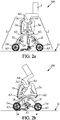
- FIG. 1a illustrates in a simplified manner a supporting structure in accordance with the invention.
- the structure which is denoted 100 as a whole, comprises a load-receiving part 1 and four legs each denoted 2.
- the legs are distributed into two pairs, each pair located on a lateral side of the load-receiving part 1, symmetrical to the other leg pair located on the other lateral side, but any leg can have an instant position different from the other legs.
- both legs which have connections to the load-receiving part 1 offset towards the front of the structure 100 one such leg on either lateral side, have symmetrical design, and also for both legs which have connections to the load-receiving part 1 offset towards the back of the structure 100.
- both legs on one and same lateral side may have symmetrical design but inverted in accordance with frontward and backward directions.
- each leg 2 extends from the load-receiving part 1 downwards in a reference leg position.
- Each leg 2 comprises an upper leg segment 2u, a lower leg segment 21, a wheel 2w, and optionally an additional extension leg segment which will be discussed later below.
- an upper end of the upper leg segment 2u is situated higher above ground than a lower end of the same upper leg segment 2u
- an upper end of the lower leg segment 2l is also situated higher than a lower end of the same lower leg segment 21, for each leg 2 separately.
- each leg 2 the upper end of the upper leg segment 2u is connected to the load-receiving part 1 through a rotational connection system having rotation axis A1, denoted first axis in the general description part above. Also the lower end of the upper leg segment 2u is connected to the upper end of the lower segment 2l in the same leg 2 through another rotational connection system having rotation axis A2, denoted second axis in the general description part. And each wheel 2w is connected to the lower end of the lower leg segment 2l within each leg 2 through still another rotational connection system having rotation axis A3.
- the four rotation axes A1, the four rotation axes A2 and possibly also the four rotation axes A3 are all horizontal and parallel, perpendicular to a vertical sagittal plane of the structure 100, located between both lateral sides.
- each rotational connection system about any one of the axes A1, A2 or A3 is provided with a motor unit (not represented) suitable for moving rotationally the connected elements with respect to one another.
- the motor units for rotations about the A1-axes and A2-axes are servomotors. All motor units for rotations about the A1-axes or A2-axes form a first motor system dedicated to changing the leg attitudes.
- the motor units arranged for driving the wheels 2w in rotation about the A3-axes form a second motor system dedicated to rolling the supporting structure 100 on the ground.
- the travelling motion of the supporting structure 100 on the ground may be produced by the four motor units which are provided respectively to the wheels 2w, by controlling consistently all wheel rotations.
- clockwise or anticlockwise rotations and speeds for all four wheels 2w may be controlled appropriately.
- slips and frictions of the rotating wheels 2w against the ground make the supporting structure 100 turning left or right.
- At least one among the first and second motor systems may be powered using batteries (not represented) arranged on-board the supporting structure 100, for example contained within or affixed to the load-receiving part 1. Control of all motor units in a coordinated manner is supposed to be accessible to the Man skilled in robotics without inventiveness.
- Figure 1b is a completed version of Figure 1a when the supporting structure 100 is dedicated to aiding a disabled person in moving on the ground.
- the load-receiving part 1 may be a seat or backrest for supporting the pelvis or trunk of the disabled person. Then, the load-receiving part 1 together with the four legs 2 form an exoskeleton capable of transporting the disabled person or helping him to travel on the ground.
- the supporting structure 100 may be further adapted so that the load-receiving part 1 can be varied in angle around an additional axis A4 located substantially between the first A1-axes on each lateral side, and parallel to the A1-axes.
- Such rotation of the seat- and/or backrest forming load-receiving part 1 allows accommodating varying attitudes of the disabled person for maintaining equilibrium.
- the supporting structure 100 may be moved on ground by the feet of the disabled person contacting and pulling the ground while his pelvis or trunk is supported by the load-receiving part 1.
- the wheels 2w may be freewheels for not impeding motion of the supporting structure 100 on the ground, as driven by the person.
- the wheels 2w may be swivel wheels with swivel axes oriented vertically for further suppressing any hindrance against the motion driven by the person.
- the supporting structure 100 dedicated to a disabled person may further comprise two jointed supports 3 designed for supporting the legs of the disabled person, or aiding him in moving his legs.
- the supports 3 may drive the person's legs into a motion which is coordinated with the motion of the supporting structure 100 on the ground.
- the supports 3 may be segmented with intermediate rotational connections for controlling the femoral, tibial and foot attitudes of the disabled person.
- each support 3 may also comprise suitable contact areas, for pressing against the thigh, calf and foot sole.
- FIGs 2a-2c show a main attitude variation produced by a supporting structure 100 in accordance with the invention.
- Such attitude variation results in a change in the height of the load receiving part 1 above the ground, denoted G.
- the legs are simultaneously bent upwards by controlling rotation of the lower leg segments 2l about the A2-axes so as to reduce the angles ⁇ between the upper leg segments 2u and the lower leg segments 21, with angle apex at the A2 axes. This results in increasing the distance d1 between the front and back wheels 2w on each lateral side, while lowering the load-receiving part 1.
- the rotations of the upper leg segments 2u with respect to the load-receiving part 1 are also activated simultaneously, for spreading out the upper leg segments 2u on each lateral side, simultaneously for both lateral sides.
- spreading out the upper leg segments 2u increases the distance d2 between the A2-axes of both legs 2 on each lateral side. In this way, the overall length of the supporting structure 100 parallel to the ground G in the lowered attitude is reduced with respect to the only bending of the legs 2 about the A2-axes.
- Abutting surfaces which may be provided to the upper leg segment 2u and lower leg segment 2l of each leg 2, may come into contact with each other for all legs, so as to block further reduction in the angles ⁇ , and thus stop the lowering of the load-receiving part 1.
- the lowering may be continued until the four legs 2 contact the ground G at the A2-axes in addition to the four wheels 2w.
- the legs 2 may each be provided with protruding portions 2p ( Figure 2c ) which are fixed with respect to the lower leg segments 2l during lowering of the load-receiving part 1. Then, the lowering may be continued until these protruding portions 2p contact the ground G.
- the rotations about the A2-axes may be continued until the wheels 2w lift above the ground G and the supporting structure 100 pushes onto the ground G only through the protruding portions 2p.
- the load-receiving part 1 forming seat and/or backrest is leant forward for helping the person to maintain his equilibrium during the sitting movement (see Figure 2b ).
- Motion reverse to the lowering just described for the supporting structure 100 leads to increasing the height of the load-receiving part 1 above the ground G. This may correspond to standing-up of the disabled person from the sitting position.
- attitudes of the supporting structure 100 with both legs 2 on each lateral side which cross each other are advantageous in a great number of situations.
- the leg of one of the lateral sides which has its A1-axis shifted backwards with respect to the A1-axis of the other leg of the same lateral side has its lower leg end at a location on the ground which is shifted forwards with respect to the lower leg end of the other leg relating to the same lateral side.
- uncrossed leg positions may be advantageous for other situations, for example when increased stability is required.
- a reference uncrossed leg position may be the four legs 2 extending straight with all angles ⁇ equalling 180°, vertically or spreading out on each lateral side of the load-receiving part 1.
- rotations of the wheels 2w may be impeded using appropriate rotation blocking arrangements, and the four legs 2 may be activated from the reference uncrossed leg position for producing a walk motion similar to that of a four-footed animal.
- Such walk motion may be more appropriate than rolling for uneven grounds, for the supporting structure 100 to travel without incurring damages.
- leg extension segments 2e which are provided at the lower ends of all legs 2. Such leg extension segments are optional but when implemented, they are each connected to the corresponding lower leg end so as to be either extended or retracted. When extended, each leg extension segment 2e contacts the ground instead of the corresponding wheel 2w. Preferably, each leg extension segment 2e may be provided at its lower end with a ground-contacting pad for avoiding any gliding of the leg 2 on the ground. Also preferably, each leg extension segment 2e increases the overall length of the corresponding leg 2, compared to this leg 2 contacting the ground with its wheel 2w. Extension or retraction of each leg extension segment 2e may be produced by a motor system, using any mechanical arrangement known in the art.
- each leg extension segment 2e may be provided with a small freewheel which is connected to this segment at an intermediate location in the length segment.
- Such small freewheel may form the protruding portion 2p, and may useful during stretching of each leg extension segment for allowing its lower end to move softly on the ground.
- Figures 3a and 3b show a first advantageous use of the leg extension segments 2e for producing the travelling motion similar to a four-footed animal in a more efficient manner. Efficiency is improved first because of avoiding that the wheels 2w can roll on the ground G, and also because the leg length is increased.
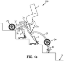
- Figures 4a and 4b show another advantageous use of the leg extension segments 2e for climbing stairs S ( Figure 4a ) or going downstairs ( Figure 4b ). It is preferable that the leg extension segments 2e are used in stairs only for the two legs 2 which are located on steps downwards, so as to compensate for the difference in the height between front legs and back legs. Driving the movements of all four legs 2 synchronously for producing the upstairs or downstairs climbing motion can then be easily programmed.
- the seat or backrest is preferably leant forwards when going upstairs ( Figure 4a ) for improving the person's equilibrium.
- the first motor system dedicated for moving the legs 2 about the A1- and A2-axes, and optionally also for extending and retracting the leg extension segments 2e may be a liquid pump coupled to liquid-controlled actuators which are arranged for being actuated by liquid pressure produced by the pump.
- the liquid pump may be electrically powered using batteries installed on-board the supporting structure.
- Each liquid-controlled actuator may be dedicated to producing rotation of one of the upper leg segments 2u or lower leg segments 2l about one of the A1- or A2-axes, separately from the other liquid-controlled actuators dedicated to producing rotations of other ones of the upper and lower segments.
- One separate liquid-controlled actuator may also be provided for extending and retracting each one of the leg extension segments. Possibly, such liquid-based motor system may be used in addition for driving the wheels 2w in rotation, so as to produce travelling of the supporting structure 100 on the ground.
- One liquid pump may be shared by all leg-moving actuators and wheel-driving devices.
- Another application of a supporting structure in accordance with the invention may be stabilization of a biped robot. Then, the load receiving part is designed for adapting to the biped robot standing on the ground, while allowing the biped robot to walk. The rotations of the wheels 2w or the movements of the legs 2 are then synchronized with the walking motion of the biped robot.
- Still another application of a supporting structure in accordance with the invention may be forming a terrestrial drone, capable of travelling on a great variety of grounds, and with variable travelling speeds. Indeed, using the leg extension segments 2e may allow travelling on uneven grounds and getting over obstacles, whereas rolling allows higher travelling speeds.
Landscapes
- Health & Medical Sciences (AREA)
- Veterinary Medicine (AREA)
- Life Sciences & Earth Sciences (AREA)
- Animal Behavior & Ethology (AREA)
- General Health & Medical Sciences (AREA)
- Public Health (AREA)
- Pain & Pain Management (AREA)
- Physical Education & Sports Medicine (AREA)
- Rehabilitation Therapy (AREA)
- Epidemiology (AREA)
- Rehabilitation Tools (AREA)
- Handcart (AREA)
- Manipulator (AREA)
Claims (15)
- Structure de support (100) comprenant :- une partie de réception de charge (1), conçue pour recevoir une charge à transporter ou à assister pendant un déplacement ;- deux paires de jambes (2), chaque paire de jambes étant agencée à partir d'un côté latéral de la partie de réception de charge qui est opposé à un autre côté latéral de ladite partie de réception de charge dédiée à l'autre paire de jambes, l'ensemble des jambes (2) s'étendant de la partie de réception de charge (1) vers le sol lorsque la structure de support (100) est en condition d'utilisation sur un sol horizontal, et étant adaptées pour maintenir la partie de réception de charge au-dessus du sol ; et- quatre roues (2w) avec des axes de rotation respectifs orientés horizontalement lorsque la structure de support (100) est en condition d'utilisation sur un sol horizontal, chaque jambe (2) étant munie de l'une desdites roues à une extrémité inférieure de ladite jambe qui est opposée à une liaison de ladite jambe à la partie de réception de charge (1) ;moyennant quoi chaque jambe (2) comprend un segment supérieur (2u) et un segment inférieur (2l), dans laquelle pour chaque jambe une extrémité supérieure du segment supérieur est reliée en rotation à la partie de réception de charge (1) avec un premier axe de rotation (A1), et une extrémité inférieure du segment supérieur est reliée en rotation à une extrémité supérieure du segment inférieur avec un second axe de rotation (A2), et une extrémité inférieure du segment inférieur formant l'extrémité de jambe inférieure opposée à la liaison de ladite jambe à la partie de réception de charge, les premier et second axes de rotation de l'ensemble des jambes étant parallèles et horizontaux lorsque la structure de support (100) est en condition d'utilisation sur un sol horizontal,
caractérisée en ce que la structure de support (100) est adaptée pour produire une position à jambes croisées de référence en condition d'utilisation sur un sol horizontal avec les roues (2w) toutes situées sur le sol, dans laquelle les deux jambes (2) sur chaque côté latéral de la partie de réception de charge (1) s'étendent vers le bas tout en se croisant mutuellement dans une projection dans un plan sagittal de la structure de support,
et la structure de support (100) est en outre adaptée pour réaliser un abaissement de la partie de réception de charge (1) vers le sol à partir de la position à jambes croisées de référence, en pliant chaque jambe (2) vers le haut autour du second axe (A2) de ladite jambe afin de réduire un angle (α) entre les segments supérieur (2u) et inférieur (2l) de ladite jambe au niveau du second axe, simultanément pour l'ensemble des quatre jambes, ce qui augmente une première distance (d1) entre les deux roues (2w) sur chaque côté latéral de la partie de réception de charge, tandis que les deux jambes sur chaque côté latéral continuent de se croiser mutuellement dans une projection dans le plan sagittal. - Structure de support (100) selon la revendication 1, adaptée en outre de sorte que, au cours de l'abaissement de la partie de réception de charge (1) à partir de la position à jambes croisées de référence, les deux segments supérieurs (2u) sur chaque côté latéral de la partie de réception de charge sont simultanément écartés par des rotations desdits segments supérieurs autour des premiers axes (A1) dans des directions opposées, afin d'augmenter une seconde distance (d2) entre les seconds axes (A2) sur chaque côté latéral de la partie de réception de charge, ce qui diminue ou supprime l'augmentation de la première distance entre les roues (2w) sur chaque côté latéral comme résultant uniquement du repliement des jambes (2) autour des seconds axes.
- Structure de support (100) selon la revendication 1 ou 2, adaptée en outre de sorte que l'abaissement de la partie de réception de charge (1) est poursuivie jusqu'à ce que des surfaces de butée respectivement reliées aux segments supérieur (2u) et inférieur (2l) de chaque jambe (2) viennent mutuellement en contact pour l'ensemble des jambes, afin d'interrompre une réduction supplémentaire de l'angle (α) entre les segments supérieur et inférieur de chaque jambe, ou jusqu'à ce que les quatre jambes viennent en contact avec le sol au niveau des quatre seconds axes (A2) en plus des quatre roues (2w).
- Structure de support (100) selon l'une quelconque des revendications précédentes, comprenant en outre au moins un premier système à moteur agencé pour entraîner les segments inférieurs (2l) des jambes (2) en rotation autour des seconds axes (A2) respectifs, et également facultativement pour entraîner simultanément les segments supérieurs (2u) des jambes (2) en rotation autour des premiers axes (A1) respectifs, au cours de l'abaissement de la partie de réception de charge (1) à partir de la position à jambes croisées de référence.
- Structure de support (100) selon la revendication 4, dans laquelle le premier système à moteur comprend des unités de moteurs dédiées chacune à produire la rotation de l'un des segments supérieur (2u) et inférieur (2l) autour de l'un des premier (A1) ou second (A2) axes, séparément des autres unités de moteurs dédiées à produire des rotations d'autres des segments supérieur et inférieur.
- Structure de support (100) selon l'une quelconque des revendications précédentes, adaptée en outre pour déplacer les jambes (2) autour des premiers axes (A1) à partir de la position à jambes croisées de référence afin de décroiser les deux jambes sur chaque côté latéral de la partie de réception de charge (1), dans une projection dans le plan sagittal, ce qui produit une position à jambes décroisées.
- Structure de support (100) selon la revendication 6, adaptée pour déplacer les jambes (2) à partir de la position à jambes décroisées afin de produire un mouvement de marche du type animal à quatre pattes.
- Structure de support (100) selon l'une quelconque des revendications précédentes, comprenant en outre au moins un second système à moteur agencé pour entraîner au moins deux des roues (2w) en rotation, de sorte que la structure de support se déplace sur le sol en roulant.
- Structure de support (100) selon l'une quelconque des revendications précédentes, dans laquelle chaque jambe (2) comprend en outre un segment d'extension de jambe rétractable (2e) agencé pour s'étendre vers le bas afin de pousser sur le sol à la place de la roue (2w) de ladite jambe, chaque segment d'extension de jambe étant muni d'un patin de contact avec le sol et ayant une longueur d'extension telle que la jambe est plus longue lorsque le segment d'extension de jambe est étendu, par rapport à la jambe venant en contact avec le sol avec la roue de ladite jambe lorsque ledit segment d'extension de jambe n'est plus étendu.
- Structure de support (100) selon la revendication 9, adaptée en outre pour être commandée pour monter une marche ou des escaliers, avec les segments d'extension de jambe (2e) étendus pour au moins deux des jambes (2).
- Structure de support (100) selon la revendication 9 ou 10, adaptée de sorte que l'extension de chaque segment d'extension de jambe (2e) est produite par un système à moteur.
- Structure de support (100) selon l'une quelconque des revendications 1 à 11, adaptée pour former un exosquelette destiné à une personne handicapée, dans laquelle la partie de réception de charge (1) est un siège ou un dossier adapté pour soutenir au moins l'un parmi un bassin ou un tronc de la personne handicapée.
- Structure de support (100) selon la revendication 12, adaptée pour que les roues (2w) soient des roues libres pendant au moins une partie de l'utilisation de ladite structure de support par la personne handicapée, et dans laquelle la structure de support est adaptée pour être déplacée sur le sol par les pieds de la personne handicapée venant en contact et par traction avec le sol tandis que le bassin ou le tronc de ladite personne handicapée est soutenu par la partie de réception de charge (1).
- Structure de support (100) selon la revendication 12 ou 13, comprenant en outre deux supports articulés (3) s'étendant à partir de la partie de réception de charge (1) et adaptés pour déplacer les jambes de la personne handicapée d'une manière coordonnée par rapport à un déplacement de la structure de support.
- Structure de support (100) selon l'une quelconque des revendications 1 à 11, dans laquelle la partie de réception de charge (1) est appropriée pour s'adapter à un robot bipède debout sur le sol tout en permettant au robot bipède de marcher, et ladite structure de support augmentant la stabilité du robot bipède.
Priority Applications (12)
| Application Number | Priority Date | Filing Date | Title |
|---|---|---|---|
| ES16305189T ES2759298T3 (es) | 2016-02-18 | 2016-02-18 | Estructura de soporte |
| EP16305189.9A EP3207909B1 (fr) | 2016-02-18 | 2016-02-18 | Structure de support |
| DK16305189T DK3207909T3 (da) | 2016-02-18 | 2016-02-18 | Støttestruktur |
| PT163051899T PT3207909T (pt) | 2016-02-18 | 2016-02-18 | Estrutura de suporte |
| RU2018130825A RU2719216C2 (ru) | 2016-02-18 | 2017-02-14 | Поддерживающая структура |
| CA3013164A CA3013164C (fr) | 2016-02-18 | 2017-02-14 | Structure de support |
| PCT/EP2017/053331 WO2017140694A1 (fr) | 2016-02-18 | 2017-02-14 | Structure de support |
| AU2017220582A AU2017220582B2 (en) | 2016-02-18 | 2017-02-14 | Supporting structure |
| CN201780011591.4A CN108697568B (zh) | 2016-02-18 | 2017-02-14 | 支撑结构 |
| JP2018544038A JP2019512287A (ja) | 2016-02-18 | 2017-02-14 | 支持構造 |
| US16/070,604 US11026852B2 (en) | 2016-02-18 | 2017-02-14 | Supporting structure |
| IL260621A IL260621B (en) | 2016-02-18 | 2018-07-16 | supporting structure |
Applications Claiming Priority (1)
| Application Number | Priority Date | Filing Date | Title |
|---|---|---|---|
| EP16305189.9A EP3207909B1 (fr) | 2016-02-18 | 2016-02-18 | Structure de support |
Publications (2)
| Publication Number | Publication Date |
|---|---|
| EP3207909A1 EP3207909A1 (fr) | 2017-08-23 |
| EP3207909B1 true EP3207909B1 (fr) | 2019-09-11 |
Family
ID=55443206
Family Applications (1)
| Application Number | Title | Priority Date | Filing Date |
|---|---|---|---|
| EP16305189.9A Active EP3207909B1 (fr) | 2016-02-18 | 2016-02-18 | Structure de support |
Country Status (12)
| Country | Link |
|---|---|
| US (1) | US11026852B2 (fr) |
| EP (1) | EP3207909B1 (fr) |
| JP (1) | JP2019512287A (fr) |
| CN (1) | CN108697568B (fr) |
| AU (1) | AU2017220582B2 (fr) |
| CA (1) | CA3013164C (fr) |
| DK (1) | DK3207909T3 (fr) |
| ES (1) | ES2759298T3 (fr) |
| IL (1) | IL260621B (fr) |
| PT (1) | PT3207909T (fr) |
| RU (1) | RU2719216C2 (fr) |
| WO (1) | WO2017140694A1 (fr) |
Families Citing this family (25)
| Publication number | Priority date | Publication date | Assignee | Title |
|---|---|---|---|---|
| JP7365356B2 (ja) * | 2017-12-15 | 2023-10-19 | エンライトゥン モビリティ エルエルシー | 医療用歩行器 |
| CN108030575A (zh) * | 2017-12-15 | 2018-05-15 | 沈阳理工大学 | 一种辅助残障动物行动的装置 |
| EP3524217B1 (fr) * | 2018-02-13 | 2021-11-17 | LG Electronics Inc. | Dispositif et système d'assistance et/ou de rééducation adaptatifs |
| US10792209B2 (en) | 2018-02-23 | 2020-10-06 | Lg Electronics Inc. | Wearable assistive device that efficiently delivers assistive force |
| WO2019177260A1 (fr) * | 2018-03-15 | 2019-09-19 | 엘지전자 주식회사 | Dispositif d'aide au renforcement musculaire pour commander l'attitude de celui-ci en fonction du mode de fonctionnement |
| WO2019177261A1 (fr) * | 2018-03-15 | 2019-09-19 | 엘지전자 주식회사 | Appareil d'assistance musculaire mettant en œuvre une opération de protection pour un système d'entraînement |
| US10603786B2 (en) | 2018-03-16 | 2020-03-31 | Lg Electronics Inc. | Belt for effective wearing and wearable assistive device having the same |
| CN108433955A (zh) | 2018-04-10 | 2018-08-24 | 广州足步医疗科技有限公司 | 一种助行机器人 |
| TWI678200B (zh) * | 2018-11-08 | 2019-12-01 | 緯創資通股份有限公司 | 移動載具 |
| CN109589215A (zh) * | 2018-11-15 | 2019-04-09 | 江南大学 | 一种越障轮椅的底盘机构 |
| CN109910017B (zh) * | 2019-04-23 | 2023-12-22 | 中铁工程装备集团有限公司 | 一种适于盾构使用的检测/换刀机器人及其使用方法 |
| US11241982B2 (en) * | 2019-06-28 | 2022-02-08 | Honda Motor Co., Ltd. | Walking infant seat |
| CN110547922B (zh) * | 2019-08-23 | 2020-07-17 | 国家康复辅具研究中心 | 一种多功能越障爬楼轮椅及越障爬楼方法 |
| US12318610B1 (en) | 2019-10-18 | 2025-06-03 | Enlighten Mobility Llc | Gait trainer with neuromodulation integration |
| US11596828B1 (en) | 2019-10-18 | 2023-03-07 | Enlighten Mobility, LLC | Gait trainer attachment |
| RU197295U1 (ru) * | 2019-12-30 | 2020-04-20 | Петр Николаевич Старков | Ходунки для людей с ограниченными возможностями с приспособлением для преодоления препятствий например ступенек лестниц. |
| CN111361659B (zh) * | 2020-03-06 | 2021-08-24 | 中国南方电网有限责任公司超高压输电公司广州局 | 一种轮腿式越障机构和越障机器人 |
| TWI731621B (zh) * | 2020-03-17 | 2021-06-21 | 緯創資通股份有限公司 | 助行器 |
| RU2765403C1 (ru) * | 2020-11-30 | 2022-01-28 | Федеральное государственное бюджетное учреждение "Санкт-Петербургский научно-исследовательский институт фтизиопульмонологии" Министерства здравоохранения Российской Федерации (ФГБУ "СПб НИИФ" Минздрава России) | Устройство реабилитации пациентов с нарушениями опорно-двигательного аппарата |
| KR102934889B1 (ko) | 2021-02-03 | 2026-03-09 | 현대자동차주식회사 | 이동체 |
| US11759385B2 (en) * | 2021-02-04 | 2023-09-19 | Stairassist Walker, Llc | Safety control for mobility device |
| EP4331777A4 (fr) | 2021-04-26 | 2025-03-05 | Lifehub Inc. | Dispositif mobile |
| CN113509328B (zh) * | 2021-07-13 | 2023-06-16 | 杭州太希智能科技有限公司 | 一种可适应多种复杂路面的多姿态康复四足机器人 |
| CN113397849B (zh) * | 2021-07-21 | 2022-09-23 | 李磊 | 一种医疗外科用可爬坡复健轮椅设备 |
| CN115366075B (zh) * | 2022-07-29 | 2025-04-18 | 杭州程天科技发展有限公司 | 一种可调节行动姿态的外骨骼 |
Family Cites Families (23)
| Publication number | Priority date | Publication date | Assignee | Title |
|---|---|---|---|---|
| DE9418858U1 (de) * | 1994-11-24 | 1996-03-28 | Paas, Dieter, Dipl.-Ing. (FH), 41464 Neuss | Gerät zum Trainieren des Gehens behinderter Personen |
| JPH11128278A (ja) * | 1997-10-21 | 1999-05-18 | Marie Lone | 階段昇降可能な車椅子 |
| US6260862B1 (en) * | 1998-02-11 | 2001-07-17 | Joseph C. Klann | Walking device |
| JP4249872B2 (ja) * | 1999-09-09 | 2009-04-08 | ファミリー株式会社 | マッサージ機 |
| CN2410927Y (zh) * | 1999-10-20 | 2000-12-20 | 卢玉林 | 多功能车椅 |
| RU25999U1 (ru) * | 2002-05-13 | 2002-11-10 | Пендейл Вентурес Лимитед | Трансформируемое персональное транспортное средство |
| BRPI0610312B8 (pt) * | 2005-05-27 | 2021-06-22 | Honda Motor Co Ltd | dispositivo de assistência à caminhada |
| RU2297206C2 (ru) * | 2005-06-15 | 2007-04-20 | Александр Дмитриевич Элизов | Трансформируемое транспортное средство |
| CA2566551C (fr) * | 2006-10-31 | 2009-04-07 | Volodymyr Ivanchenko | Appareil pour le transport d'une personne handicapee |
| WO2008152759A1 (fr) * | 2007-06-11 | 2008-12-18 | Panasonic Corporation | Mécanisme mobile de type roue à jambe |
| JP5283282B2 (ja) * | 2007-10-02 | 2013-09-04 | 学校法人東京理科大学 | 歩行補助装置 |
| KR101043207B1 (ko) * | 2008-10-22 | 2011-06-22 | 서강대학교산학협력단 | 휠체어식 보행 보조용 로봇 |
| CN101811525B (zh) * | 2010-04-23 | 2012-05-23 | 山东大学 | 具有质心调整装置的液压驱动四足机器人移动机构 |
| CN101898594B (zh) * | 2010-07-28 | 2012-05-16 | 清华大学 | 一种动力式双足机器人行走方法 |
| CN102085145B (zh) * | 2010-11-29 | 2014-06-25 | 燕山大学 | 一种用于四足/两足并联腿步行机器人的可重构装置 |
| KR101224056B1 (ko) * | 2011-06-27 | 2013-01-21 | 엘지전자 주식회사 | 보행 보조 장치 및 그 작동 제어 방법 |
| CN102351018B (zh) * | 2011-08-11 | 2013-02-06 | 西北工业大学 | 一种四足机器人腿部关节 |
| DE102011087253A1 (de) | 2011-11-28 | 2013-05-29 | AMS MEKATRONIK SISTEMLER AR-GE MÜHENDISLIK YAZILIM SANAYI VE TICARET Anonim Sirketi | Transportvorrichtung |
| US9510981B2 (en) * | 2013-03-14 | 2016-12-06 | Stryker Corporation | Reconfigurable transport apparatus |
| GB2514604B (en) * | 2013-05-30 | 2015-11-11 | Step Up Olim Madrega Ltd | Wheelchair curb-climbing and curb-descending system |
| US20160022517A1 (en) * | 2014-07-22 | 2016-01-28 | Purdue Research Foundation | Mobility-assistance apparatus and method of using same |
| CN104890759B (zh) * | 2015-07-10 | 2017-06-16 | 陕西九立机器人制造有限公司 | 一种四足机器人 |
| US10245204B2 (en) * | 2015-09-11 | 2019-04-02 | Ekso Bionics, Inc. | Devices and methods for improving the utility of an exoskeleton mobility base |
-
2016
- 2016-02-18 ES ES16305189T patent/ES2759298T3/es active Active
- 2016-02-18 DK DK16305189T patent/DK3207909T3/da active
- 2016-02-18 EP EP16305189.9A patent/EP3207909B1/fr active Active
- 2016-02-18 PT PT163051899T patent/PT3207909T/pt unknown
-
2017
- 2017-02-14 CA CA3013164A patent/CA3013164C/fr active Active
- 2017-02-14 WO PCT/EP2017/053331 patent/WO2017140694A1/fr not_active Ceased
- 2017-02-14 AU AU2017220582A patent/AU2017220582B2/en not_active Ceased
- 2017-02-14 CN CN201780011591.4A patent/CN108697568B/zh not_active Expired - Fee Related
- 2017-02-14 JP JP2018544038A patent/JP2019512287A/ja active Pending
- 2017-02-14 RU RU2018130825A patent/RU2719216C2/ru active
- 2017-02-14 US US16/070,604 patent/US11026852B2/en not_active Expired - Fee Related
-
2018
- 2018-07-16 IL IL260621A patent/IL260621B/en unknown
Non-Patent Citations (1)
| Title |
|---|
| SAMI J YLÖNEN ET AL: "WorkPartner -centaur like service robot WorkPartner -Centaur like Service Robot", PROCEEDINGS OF THE 2002 IEEE/RSJ INTERNATIONAL CONFERENCE ON INTELLIGENT ROBOTS AND SYSTEMS, 1 January 2002 (2002-01-01), pages 727 - 732, XP055570055, DOI: 10.1109/IRDS.2002.1041477.Source: * |
Also Published As
| Publication number | Publication date |
|---|---|
| RU2719216C2 (ru) | 2020-04-17 |
| US20190015273A1 (en) | 2019-01-17 |
| AU2017220582B2 (en) | 2021-01-28 |
| DK3207909T3 (da) | 2019-12-09 |
| CN108697568B (zh) | 2019-11-12 |
| PT3207909T (pt) | 2019-12-17 |
| AU2017220582A1 (en) | 2018-08-02 |
| EP3207909A1 (fr) | 2017-08-23 |
| CA3013164C (fr) | 2024-04-09 |
| US11026852B2 (en) | 2021-06-08 |
| JP2019512287A (ja) | 2019-05-16 |
| ES2759298T3 (es) | 2020-05-08 |
| RU2018130825A (ru) | 2020-03-18 |
| RU2018130825A3 (fr) | 2020-03-18 |
| CA3013164A1 (fr) | 2017-08-24 |
| IL260621B (en) | 2022-02-01 |
| CN108697568A (zh) | 2018-10-23 |
| WO2017140694A1 (fr) | 2017-08-24 |
Similar Documents
| Publication | Publication Date | Title |
|---|---|---|
| EP3207909B1 (fr) | Structure de support | |
| JP6307023B2 (ja) | 輸送装置 | |
| Quaglia et al. | Design of a self-leveling cam mechanism for a stair climbing wheelchair | |
| CN102755229B (zh) | 一种六足楼梯攀爬轮椅 | |
| KR101356520B1 (ko) | 보행 보조 시스템 | |
| US20190231617A1 (en) | Mobility assistance vehicle designed to negotiate obstacles | |
| JP2017520352A (ja) | 昇降歩行器椅子、持上げデバイス、及びリハビリテーションの方法 | |
| KR101363850B1 (ko) | 지능형 근력 및 보행 보조용 로봇 | |
| KR101215285B1 (ko) | 턱이 있는 보도에서도 주행이 가능한 전동 휠체어 | |
| JP2018532638A (ja) | 多様な支持面を移動するためのホイール式歩行移動機構を有するシャシー | |
| JP6209185B2 (ja) | 移乗支援装置 | |
| US9387145B2 (en) | Care support apparatus | |
| JP2004097712A (ja) | 四足歩行装置 | |
| JP7033357B1 (ja) | 運搬器具 | |
| HK1260157B (en) | Supporting structure | |
| HK1260157A1 (en) | Supporting structure | |
| CN110723231A (zh) | 一种双足平行地面行走机器人 | |
| TWI724616B (zh) | 3d輪椅機器人 | |
| JP2011092446A (ja) | 移動補助装置 | |
| JP2026512260A (ja) | ロボットの動作処理方法と装置、ロボット、電子機器及びコンピュータプログラム | |
| Mori et al. | Passing over several steps using a pair of step-climbing units for a manual wheelchair user | |
| KR20000066391A (ko) | 계단을 오를 수 있는 휠체어 |
Legal Events
| Date | Code | Title | Description |
|---|---|---|---|
| PUAI | Public reference made under article 153(3) epc to a published international application that has entered the european phase |
Free format text: ORIGINAL CODE: 0009012 |
|
| STAA | Information on the status of an ep patent application or granted ep patent |
Free format text: STATUS: THE APPLICATION HAS BEEN PUBLISHED |
|
| AK | Designated contracting states |
Kind code of ref document: A1 Designated state(s): AL AT BE BG CH CY CZ DE DK EE ES FI FR GB GR HR HU IE IS IT LI LT LU LV MC MK MT NL NO PL PT RO RS SE SI SK SM TR |
|
| AX | Request for extension of the european patent |
Extension state: BA ME |
|
| STAA | Information on the status of an ep patent application or granted ep patent |
Free format text: STATUS: REQUEST FOR EXAMINATION WAS MADE |
|
| 17P | Request for examination filed |
Effective date: 20180215 |
|
| RBV | Designated contracting states (corrected) |
Designated state(s): AL AT BE BG CH CY CZ DE DK EE ES FI FR GB GR HR HU IE IS IT LI LT LU LV MC MK MT NL NO PL PT RO RS SE SI SK SM TR |
|
| RAP1 | Party data changed (applicant data changed or rights of an application transferred) |
Owner name: HEXOWHEEL |
|
| RIN1 | Information on inventor provided before grant (corrected) |
Inventor name: LINON, RODOLPHE |
|
| RIC1 | Information provided on ipc code assigned before grant |
Ipc: A61G 5/04 20130101ALI20190315BHEP Ipc: A61H 3/04 20060101ALI20190315BHEP Ipc: A61H 1/02 20060101ALI20190315BHEP Ipc: A61H 3/00 20060101ALI20190315BHEP Ipc: A61G 5/14 20060101AFI20190315BHEP Ipc: A61G 5/12 20060101ALI20190315BHEP Ipc: A61G 5/06 20060101ALI20190315BHEP |
|
| GRAP | Despatch of communication of intention to grant a patent |
Free format text: ORIGINAL CODE: EPIDOSNIGR1 |
|
| STAA | Information on the status of an ep patent application or granted ep patent |
Free format text: STATUS: GRANT OF PATENT IS INTENDED |
|
| INTG | Intention to grant announced |
Effective date: 20190426 |
|
| GRAS | Grant fee paid |
Free format text: ORIGINAL CODE: EPIDOSNIGR3 |
|
| GRAA | (expected) grant |
Free format text: ORIGINAL CODE: 0009210 |
|
| STAA | Information on the status of an ep patent application or granted ep patent |
Free format text: STATUS: THE PATENT HAS BEEN GRANTED |
|
| AK | Designated contracting states |
Kind code of ref document: B1 Designated state(s): AL AT BE BG CH CY CZ DE DK EE ES FI FR GB GR HR HU IE IS IT LI LT LU LV MC MK MT NL NO PL PT RO RS SE SI SK SM TR |
|
| REG | Reference to a national code |
Ref country code: GB Ref legal event code: FG4D |
|
| REG | Reference to a national code |
Ref country code: CH Ref legal event code: EP |
|
| REG | Reference to a national code |
Ref country code: AT Ref legal event code: REF Ref document number: 1177541 Country of ref document: AT Kind code of ref document: T Effective date: 20190915 |
|
| REG | Reference to a national code |
Ref country code: DE Ref legal event code: R096 Ref document number: 602016020324 Country of ref document: DE Ref country code: IE Ref legal event code: FG4D |
|
| REG | Reference to a national code |
Ref country code: DK Ref legal event code: T3 Effective date: 20191203 |
|
| REG | Reference to a national code |
Ref country code: PT Ref legal event code: SC4A Ref document number: 3207909 Country of ref document: PT Date of ref document: 20191217 Kind code of ref document: T Free format text: AVAILABILITY OF NATIONAL TRANSLATION Effective date: 20191202 |
|
| REG | Reference to a national code |
Ref country code: SE Ref legal event code: TRGR |
|
| REG | Reference to a national code |
Ref country code: NL Ref legal event code: FP |
|
| REG | Reference to a national code |
Ref country code: LT Ref legal event code: MG4D |
|
| PG25 | Lapsed in a contracting state [announced via postgrant information from national office to epo] |
Ref country code: HR Free format text: LAPSE BECAUSE OF FAILURE TO SUBMIT A TRANSLATION OF THE DESCRIPTION OR TO PAY THE FEE WITHIN THE PRESCRIBED TIME-LIMIT Effective date: 20190911 Ref country code: BG Free format text: LAPSE BECAUSE OF FAILURE TO SUBMIT A TRANSLATION OF THE DESCRIPTION OR TO PAY THE FEE WITHIN THE PRESCRIBED TIME-LIMIT Effective date: 20191211 Ref country code: LT Free format text: LAPSE BECAUSE OF FAILURE TO SUBMIT A TRANSLATION OF THE DESCRIPTION OR TO PAY THE FEE WITHIN THE PRESCRIBED TIME-LIMIT Effective date: 20190911 Ref country code: FI Free format text: LAPSE BECAUSE OF FAILURE TO SUBMIT A TRANSLATION OF THE DESCRIPTION OR TO PAY THE FEE WITHIN THE PRESCRIBED TIME-LIMIT Effective date: 20190911 |
|
| REG | Reference to a national code |
Ref country code: NO Ref legal event code: T2 Effective date: 20190911 |
|
| REG | Reference to a national code |
Ref country code: CH Ref legal event code: NV Representative=s name: VALIPAT S.A. C/O BOVARD SA NEUCHATEL, CH |
|
| PG25 | Lapsed in a contracting state [announced via postgrant information from national office to epo] |
Ref country code: RS Free format text: LAPSE BECAUSE OF FAILURE TO SUBMIT A TRANSLATION OF THE DESCRIPTION OR TO PAY THE FEE WITHIN THE PRESCRIBED TIME-LIMIT Effective date: 20190911 Ref country code: GR Free format text: LAPSE BECAUSE OF FAILURE TO SUBMIT A TRANSLATION OF THE DESCRIPTION OR TO PAY THE FEE WITHIN THE PRESCRIBED TIME-LIMIT Effective date: 20191212 Ref country code: AL Free format text: LAPSE BECAUSE OF FAILURE TO SUBMIT A TRANSLATION OF THE DESCRIPTION OR TO PAY THE FEE WITHIN THE PRESCRIBED TIME-LIMIT Effective date: 20190911 Ref country code: LV Free format text: LAPSE BECAUSE OF FAILURE TO SUBMIT A TRANSLATION OF THE DESCRIPTION OR TO PAY THE FEE WITHIN THE PRESCRIBED TIME-LIMIT Effective date: 20190911 |
|
| PG25 | Lapsed in a contracting state [announced via postgrant information from national office to epo] |
Ref country code: EE Free format text: LAPSE BECAUSE OF FAILURE TO SUBMIT A TRANSLATION OF THE DESCRIPTION OR TO PAY THE FEE WITHIN THE PRESCRIBED TIME-LIMIT Effective date: 20190911 Ref country code: RO Free format text: LAPSE BECAUSE OF FAILURE TO SUBMIT A TRANSLATION OF THE DESCRIPTION OR TO PAY THE FEE WITHIN THE PRESCRIBED TIME-LIMIT Effective date: 20190911 Ref country code: PL Free format text: LAPSE BECAUSE OF FAILURE TO SUBMIT A TRANSLATION OF THE DESCRIPTION OR TO PAY THE FEE WITHIN THE PRESCRIBED TIME-LIMIT Effective date: 20190911 |
|
| REG | Reference to a national code |
Ref country code: ES Ref legal event code: FG2A Ref document number: 2759298 Country of ref document: ES Kind code of ref document: T3 Effective date: 20200508 |
|
| PG25 | Lapsed in a contracting state [announced via postgrant information from national office to epo] |
Ref country code: SM Free format text: LAPSE BECAUSE OF FAILURE TO SUBMIT A TRANSLATION OF THE DESCRIPTION OR TO PAY THE FEE WITHIN THE PRESCRIBED TIME-LIMIT Effective date: 20190911 Ref country code: SK Free format text: LAPSE BECAUSE OF FAILURE TO SUBMIT A TRANSLATION OF THE DESCRIPTION OR TO PAY THE FEE WITHIN THE PRESCRIBED TIME-LIMIT Effective date: 20190911 Ref country code: IS Free format text: LAPSE BECAUSE OF FAILURE TO SUBMIT A TRANSLATION OF THE DESCRIPTION OR TO PAY THE FEE WITHIN THE PRESCRIBED TIME-LIMIT Effective date: 20200224 Ref country code: CZ Free format text: LAPSE BECAUSE OF FAILURE TO SUBMIT A TRANSLATION OF THE DESCRIPTION OR TO PAY THE FEE WITHIN THE PRESCRIBED TIME-LIMIT Effective date: 20190911 |
|
| REG | Reference to a national code |
Ref country code: DE Ref legal event code: R097 Ref document number: 602016020324 Country of ref document: DE |
|
| PLBE | No opposition filed within time limit |
Free format text: ORIGINAL CODE: 0009261 |
|
| STAA | Information on the status of an ep patent application or granted ep patent |
Free format text: STATUS: NO OPPOSITION FILED WITHIN TIME LIMIT |
|
| PG2D | Information on lapse in contracting state deleted |
Ref country code: IS |
|
| PG25 | Lapsed in a contracting state [announced via postgrant information from national office to epo] |
Ref country code: IS Free format text: LAPSE BECAUSE OF FAILURE TO SUBMIT A TRANSLATION OF THE DESCRIPTION OR TO PAY THE FEE WITHIN THE PRESCRIBED TIME-LIMIT Effective date: 20200112 |
|
| 26N | No opposition filed |
Effective date: 20200615 |
|
| PG25 | Lapsed in a contracting state [announced via postgrant information from national office to epo] |
Ref country code: SI Free format text: LAPSE BECAUSE OF FAILURE TO SUBMIT A TRANSLATION OF THE DESCRIPTION OR TO PAY THE FEE WITHIN THE PRESCRIBED TIME-LIMIT Effective date: 20190911 |
|
| REG | Reference to a national code |
Ref country code: AT Ref legal event code: UEP Ref document number: 1177541 Country of ref document: AT Kind code of ref document: T Effective date: 20190911 |
|
| PG25 | Lapsed in a contracting state [announced via postgrant information from national office to epo] |
Ref country code: TR Free format text: LAPSE BECAUSE OF FAILURE TO SUBMIT A TRANSLATION OF THE DESCRIPTION OR TO PAY THE FEE WITHIN THE PRESCRIBED TIME-LIMIT Effective date: 20190911 Ref country code: MT Free format text: LAPSE BECAUSE OF FAILURE TO SUBMIT A TRANSLATION OF THE DESCRIPTION OR TO PAY THE FEE WITHIN THE PRESCRIBED TIME-LIMIT Effective date: 20190911 Ref country code: CY Free format text: LAPSE BECAUSE OF FAILURE TO SUBMIT A TRANSLATION OF THE DESCRIPTION OR TO PAY THE FEE WITHIN THE PRESCRIBED TIME-LIMIT Effective date: 20190911 |
|
| PG25 | Lapsed in a contracting state [announced via postgrant information from national office to epo] |
Ref country code: MK Free format text: LAPSE BECAUSE OF FAILURE TO SUBMIT A TRANSLATION OF THE DESCRIPTION OR TO PAY THE FEE WITHIN THE PRESCRIBED TIME-LIMIT Effective date: 20190911 |
|
| PGFP | Annual fee paid to national office [announced via postgrant information from national office to epo] |
Ref country code: LU Payment date: 20240226 Year of fee payment: 9 |
|
| PGFP | Annual fee paid to national office [announced via postgrant information from national office to epo] |
Ref country code: IE Payment date: 20240221 Year of fee payment: 9 Ref country code: NL Payment date: 20240226 Year of fee payment: 9 Ref country code: ES Payment date: 20240306 Year of fee payment: 9 |
|
| PGFP | Annual fee paid to national office [announced via postgrant information from national office to epo] |
Ref country code: AT Payment date: 20240222 Year of fee payment: 9 |
|
| PGFP | Annual fee paid to national office [announced via postgrant information from national office to epo] |
Ref country code: MC Payment date: 20240226 Year of fee payment: 9 |
|
| PGFP | Annual fee paid to national office [announced via postgrant information from national office to epo] |
Ref country code: DE Payment date: 20240213 Year of fee payment: 9 Ref country code: GB Payment date: 20240221 Year of fee payment: 9 Ref country code: PT Payment date: 20240122 Year of fee payment: 9 Ref country code: CH Payment date: 20240301 Year of fee payment: 9 |
|
| PGFP | Annual fee paid to national office [announced via postgrant information from national office to epo] |
Ref country code: SE Payment date: 20240215 Year of fee payment: 9 Ref country code: NO Payment date: 20240226 Year of fee payment: 9 Ref country code: IT Payment date: 20240123 Year of fee payment: 9 Ref country code: DK Payment date: 20240227 Year of fee payment: 9 Ref country code: BE Payment date: 20240226 Year of fee payment: 9 |
|
| REG | Reference to a national code |
Ref country code: DE Ref legal event code: R119 Ref document number: 602016020324 Country of ref document: DE |
|
| PG25 | Lapsed in a contracting state [announced via postgrant information from national office to epo] |
Ref country code: MC Free format text: LAPSE BECAUSE OF NON-PAYMENT OF DUE FEES Effective date: 20250228 |
|
| REG | Reference to a national code |
Ref country code: DK Ref legal event code: EBP Effective date: 20250228 |
|
| REG | Reference to a national code |
Ref country code: SE Ref legal event code: EUG Ref country code: CH Ref legal event code: PL |
|
| REG | Reference to a national code |
Ref country code: NL Ref legal event code: MM Effective date: 20250301 |
|
| PG25 | Lapsed in a contracting state [announced via postgrant information from national office to epo] |
Ref country code: PT Free format text: LAPSE BECAUSE OF NON-PAYMENT OF DUE FEES Effective date: 20250818 |
|
| PG25 | Lapsed in a contracting state [announced via postgrant information from national office to epo] |
Ref country code: NO Free format text: LAPSE BECAUSE OF NON-PAYMENT OF DUE FEES Effective date: 20250228 |
|
| PG25 | Lapsed in a contracting state [announced via postgrant information from national office to epo] |
Ref country code: LU Free format text: LAPSE BECAUSE OF NON-PAYMENT OF DUE FEES Effective date: 20250218 |
|
| REG | Reference to a national code |
Ref country code: AT Ref legal event code: MM01 Ref document number: 1177541 Country of ref document: AT Kind code of ref document: T Effective date: 20250218 |
|
| PG25 | Lapsed in a contracting state [announced via postgrant information from national office to epo] |
Ref country code: AT Free format text: LAPSE BECAUSE OF NON-PAYMENT OF DUE FEES Effective date: 20250218 |
|
| PG25 | Lapsed in a contracting state [announced via postgrant information from national office to epo] |
Ref country code: CH Free format text: LAPSE BECAUSE OF NON-PAYMENT OF DUE FEES Effective date: 20250228 |
|
| GBPC | Gb: european patent ceased through non-payment of renewal fee |
Effective date: 20250218 |
|
| PG25 | Lapsed in a contracting state [announced via postgrant information from national office to epo] |
Ref country code: NL Free format text: LAPSE BECAUSE OF NON-PAYMENT OF DUE FEES Effective date: 20250301 |
|
| REG | Reference to a national code |
Ref country code: BE Ref legal event code: MM Effective date: 20250228 |
|
| PG25 | Lapsed in a contracting state [announced via postgrant information from national office to epo] |
Ref country code: DE Free format text: LAPSE BECAUSE OF NON-PAYMENT OF DUE FEES Effective date: 20250902 |
|
| PG25 | Lapsed in a contracting state [announced via postgrant information from national office to epo] |
Ref country code: GB Free format text: LAPSE BECAUSE OF NON-PAYMENT OF DUE FEES Effective date: 20250218 |
|
| PG25 | Lapsed in a contracting state [announced via postgrant information from national office to epo] |
Ref country code: DK Free format text: LAPSE BECAUSE OF NON-PAYMENT OF DUE FEES Effective date: 20250228 |
|
| PG25 | Lapsed in a contracting state [announced via postgrant information from national office to epo] |
Ref country code: IT Free format text: LAPSE BECAUSE OF NON-PAYMENT OF DUE FEES Effective date: 20250218 |
|
| PG25 | Lapsed in a contracting state [announced via postgrant information from national office to epo] |
Ref country code: BE Free format text: LAPSE BECAUSE OF NON-PAYMENT OF DUE FEES Effective date: 20250228 |
|
| PG25 | Lapsed in a contracting state [announced via postgrant information from national office to epo] |
Ref country code: IE Free format text: LAPSE BECAUSE OF NON-PAYMENT OF DUE FEES Effective date: 20250218 |
|
| REG | Reference to a national code |
Ref country code: ES Ref legal event code: FD2A Effective date: 20260401 |
|
| PG25 | Lapsed in a contracting state [announced via postgrant information from national office to epo] |
Ref country code: ES Free format text: LAPSE BECAUSE OF NON-PAYMENT OF DUE FEES Effective date: 20250219 |
|
| PGFP | Annual fee paid to national office [announced via postgrant information from national office to epo] |
Ref country code: FR Payment date: 20260217 Year of fee payment: 11 |