EP3207958B1 - Guidage latéral pour une fermeture coupe-feu et fermeture coupe-feu équipée de guidage latéraux - Google Patents
Guidage latéral pour une fermeture coupe-feu et fermeture coupe-feu équipée de guidage latéraux Download PDFInfo
- Publication number
- EP3207958B1 EP3207958B1 EP17155670.7A EP17155670A EP3207958B1 EP 3207958 B1 EP3207958 B1 EP 3207958B1 EP 17155670 A EP17155670 A EP 17155670A EP 3207958 B1 EP3207958 B1 EP 3207958B1
- Authority
- EP
- European Patent Office
- Prior art keywords
- guide
- fire protection
- guide rail
- curtain
- lateral
- Prior art date
- Legal status (The legal status is an assumption and is not a legal conclusion. Google has not performed a legal analysis and makes no representation as to the accuracy of the status listed.)
- Active
Links
Images


Classifications
-
- A—HUMAN NECESSITIES
- A62—LIFE-SAVING; FIRE-FIGHTING
- A62C—FIRE-FIGHTING
- A62C2/00—Fire prevention or containment
- A62C2/06—Physical fire-barriers
- A62C2/10—Fire-proof curtains
-
- A—HUMAN NECESSITIES
- A62—LIFE-SAVING; FIRE-FIGHTING
- A62C—FIRE-FIGHTING
- A62C2/00—Fire prevention or containment
- A62C2/06—Physical fire-barriers
- A62C2/065—Physical fire-barriers having as the main closure device materials, whose characteristics undergo an irreversible change under high temperatures, e.g. intumescent
Definitions
- the present invention relates to a side guide for a fire protection closure, which has at least one guide rail, wherein the side guide enables a fire protection closure to be moved along the guide rail.
- the side guide is sufficiently resistant, in particular in the event of a full-scale fire.
- the present invention also relates to a fire protection closure guided by at least one such side guide.
- a fire protection curtain of a fire protection closure guided on two sides by such a side guide can be deployed over a large area.
- Guide elements located on one side of the curtain support the guidance of the curtain.
- side guides for closures can have special design features in addition to the guidance aspect, which are usually derived from the special requirements placed on the closures. Therefore, different types of closures usually also have specifically designed side guides.
- the following publications provide some examples of such side guides and closures.
- a guide rail of a roller shutter guide described in the publication includes an inner rail, which is typically made of plastic or metal as a rod extrusion. A side edge of a roller shutter curtain is guided in a groove of such a guide rail. For reasons of appearance, an outer rail made of wood can surround such an inner rail.
- the US 2011/0 061 822 A1 (Applicant: Storm Solutions, Inc.; Disclosure date: March 17, 2011 ) proposes a flexible curtain that can be threaded into retention channels on both sides and can be rolled up compactly using a mechanism to protect building openings during a storm.
- a blackout curtain is described in the patent application FR 1 260 823 A (Applicant: M. Herbert Reppert; Filing date: April 8, 1960 ), the side slides of which have two opposing wooden strips inside, which are intended for the attachment of cover strips.
- curtains designed to provide protection against storms are, for example, from the patent application US 2006/ 0 151 132 A1 (Applicant: Augustus Scalfani, et al.; Filing date: January 13, 2006 ), whereby such a curtain is guided in a slot in a side frame.
- US 2011/ 0 061 822 A1 Applicant: Storm Solutions, Inc.; Filing date: September 15, 2010
- a curtain with sewn-in loops on its edge can be guided over a wooden hem rod.
- closures and the guides provided for their side edges have in common is that they are only intended to improve protection against environmental influences such as light, wind and weather.
- a side guide for a roll-up protective curtain is known from the utility model DE 299 22 593 U1 (Applicant: Stöbich Brandschutz GmbH & Co. KG; filing date: 23.12.1999 ).
- the protective curtain is designed to prevent the spread of fire and smoke by creating a dividing surface on the side guide to divide the room, at least temporarily in the event of a fire.
- forces act across the curtain surface, which can lead to obstructions when winding up or unwinding the curtain.
- DE 299 22 593 U1 It is suggested that the curtain sides be held with a side seam.
- the side guide comprises a rod element that is arranged on the building side and over which the hem of the curtain is pulled.
- the rod element can also be held to the guide profile with a support element, whereby a layer of the hem should be able to be inserted between the support element and the rod element.
- the hem must be widened when pulled onto the rod element, which is why additional forces must be applied when unrolling the protective curtain, which can slow down the unrolling process. A possible risk of jams when unrolling the curtain cannot be completely ruled out.
- a slightly different concept of a lateral guide is described in the utility model DE 20 2004 018 977 U1 (Owner: Stöbich Brandtik GmbH & Co. KG; Registration date: 08.12.2004 ), with particular emphasis on improving the sealing arrangement for a fire or smoke curtain.
- the guide rails for the curtain are also made up of several parts, with fastening elements such as in Figure 3 the DE 20 2004 018 977 U1 shown, protrude into an inner area in which the rollers or sliding elements are located.
- the curtain should run through an area with so-called "zig-zag"-shaped projections and depressions, which, like on an associated curtain box, are probably formed by metal sheets.
- WO 2016/003 366 A1 (Applicant: Gliderol Doors (S) Pte. Ltd.; Publication date: 07.01.2016 ) is an insulated fire barrier that is to be composed of several plates. The plates are to be stacked next to each other when the barrier is open and arranged one above the other when closed by inserting them into a side guide.
- a guide rail for a smoke and/or fire curtain in accordance with DE 20 2015 100 372 U1 should be made of a metal profile, possibly with a filling of a cooling material.
- the guide rail should have a guide profile strip.
- a pull-out protection device should prevent the edge area of a smoke and/or fire protection curtain from being pulled out.
- An elastic element should provide pre-tensioning of the curtain.
- the DE 20 2010 009 538 U1 (Owner: Hoefnagels Projectzonwering BV; Publication date in the Patent Gazette: 02.12.2010 ) describes a fire-retardant roller blind that has a double-walled curtain made of a fire-resistant material.
- a thermally expandable material is to be arranged between the walls of the curtain.
- the walls are to be constructed from parallel panels that extend across the width of the curtain and are sewn together, with an inner strip that is rigidly connected to the opposite wall.
- the roller blind is to be guided by extensions or coupling elements through a hollow casing on the side that extends over the height of a room and is to be covered with a thermally insulating panel.
- the product standard DIN FprEN 16034:2014 specifies performance characteristics for fire and/or smoke protection for doors, gates and windows.
- the standard DIN EN 1634-1:2014 deals specifically with fire resistance tests and DIN EN 1634-3:2014 with the testing of smoke protection closures. The results of the tests are incorporated into classifications that are laid down in the standard DIN EN 13501-2:2003.
- the letter “E” therefore indicates Requirements for room closure, with the letter “I” requirements with regard to thermal insulation and with the letter "W” requirements with regard to radiation limitation, which include classification times which are to be specified in minutes and which must therefore be observed over specified periods of time.
- Laterally movable fire protection closures require reliable side guides that comply with the relevant fire protection regulations, with interested parties often expressing a desire for production to be as environmentally friendly as possible. Preferably, production should be cost-effective using common processes.
- Other aspects include making the installation of fire protection closures as easy as possible and improving operational safety, particularly for long-term operation of fire protection closures.
- a fire protection closure In many buildings, especially in old buildings, there are areas where people stay and installations for which special protective measures must be taken in the event of a fire or smoke spreading. In order to limit the risk of a fire in the building, fire protection closures are installed that must be activated in the event of a fire.
- a fire protection closure separates two room areas from each other.
- a side guide is required for a sealing connection between the closure and a part of the building, such as a wall or a passage frame.
- the side guide can comprise several components. The side guide makes it easier to move the fire protection closure if a room separation is to be created in the shortest possible time.
- the fire protection closure is held in a ceiling area or a lintel area so that the closure can be extended to the floor with the help of gravity.
- Side guides extend in a vertical direction. Side guides can also be used horizontally, for example if a ceiling opening or a floor opening is to be closed.
- the fire protection closure can be wound up in a winding box as a fire curtain that can be quickly pulled out in the event of a fire.
- Both the materials of the fire protection closure and the materials of the side guide must have sufficient fire resistance, or in other words, at least be flame-retardant.
- Side guides should withstand fire for at least 30 minutes. The side guide must ensure that the fire protection closure remains in position after it has been closed and that the protective effect is not lost prematurely.
- Band protection side guides can also be used for closures such as rolling, lifting, sectional, lifting and sliding doors specified for fire protection.
- a side guide comprises at least one guide rail.
- the guide rail is a component of the side guide.
- the guide rail is preferably located on a side area of the fire protection closure. At least one edge, preferably two edges, of the fire protection closure can be enclosed by the side guide. The enclosure can be caused by the closure entering the side guide.
- a fire protection closure can be moved along the side guide.
- a predominantly lateral movement is possible.
- a lateral movement is a movement that is limited by the guide rail.
- a first direction of movement can be more limited than a second direction of movement.
- At least one direction of movement is a longitudinal direction of movement. It is possible for the fire protection closure to cling to the guide rail at least in part during movement.
- Side guides are preferably used in pairs, in particular as parallel guides, with the fire protection closure extending between the side guides. It can also be said that the fire protection closure can be extended in the side guides.
- the side guide has a block-like, elongated shape, like a rod.
- the side guide comprises a guide channel.
- the guide channel is a part, such as an area, of the guide rail.
- the guide channel is preferably located in the guide rail.
- the guide rail delimits the guide channel.
- Several guide channel sides can be assigned to the guide channel.
- the guide channel sides are in particular part of the guide rail.
- a side guide is provided on at least four sides.
- the guide channel is incorporated into the guide rail.
- the guide channel can be designed to be mirror-symmetrical with respect to a mirror plane that can be laid structurally through the guide channel.
- the guide rail is made entirely of wood.
- All components of the guide rail that make up the guide channel are made of wood. Due to the low heat conduction, a guide channel with at least one side made of wood is advantageous.
- the guide channel is made entirely of wood. A wood that is flame-retardant is particularly suitable.
- wood is basically a combustible material
- experience has shown that wood must be exposed to an open flame for a relatively long time before it can start to burn.
- the desired combustion is therefore usually accelerated by chipping wood.
- surface-treated and thus smoothed wood is used as a guide rail.
- the treated surface is particularly chip- and splinter-free.
- the combustion properties of types of wood are known or can be calculated. On the basis of the calculations, a very effective construction geometry can be determined that offers a sufficiently long durability against combustion. It is even possible to reduce the use of materials to a minimum on the basis of the calculations.
- Wood has many advantageous properties for fire protection that are generally not considered due to the fact that wood is generally combustible.
- wood is a very good thermal insulator. In the event of a fire, wood remains largely free of distortion. If a guide rail is installed on a building, hardly any stresses from the fire protection seal are transferred to the building in the event of a fire. The building's statics are hardly affected by the subsequent installation of wooden side guides. Guide rails made of wood can be tested and classified for their fire resistance using standardized test procedures. In contrast to steel, wood is an easy-to-work material that dulls conventional processing tools relatively slowly. Wood is also relatively light. It is possible to use wood for fire protection without additional cladding or coatings.
- wood Due to the good workability of wood, the energy required to produce guide rails is low. As a renewable natural product, wood is also completely biodegradable, recyclable and does not cause any disposal problems, e.g. when a building is demolished. Guide rails made of wood can be manufactured in a very environmentally friendly way. In addition, wood is often used in residential areas in particular because of its optical properties and the feeling of space. Wood is a preferred building material, particularly for listed old buildings that are to be subsequently upgraded to improve fire protection. in order to use as few materials as possible that were not yet available at the time when an old building was constructed.
- the guide channel is limited on at least four sides.
- the guide channel has a clear cross-section and has a passage to a free interior area on at least one side.
- the side extends continuously, in particular between the inlet end and the end end of the guide channel.
- the term four-sided limitation can also be understood to mean that, viewed at the cross-section, there is a limitation in four directions of space, whereby the limitation, at least in one spatial direction, is not a final limitation.
- the guide channel serves to accommodate at least one guide element, such as a sequence of guide elements.
- Guide elements are arranged in such a way that they can be inserted into the guide channel.
- the guide elements are connected to the fire protection closure, in particular to an edge region of the fire protection closure.
- At least one surface of the guide rail is designed, e.g. smooth and free of obstacles, so that a guide element can be moved on it.
- all surfaces of the guide channel are free of obstacles to movement.
- the guide element can also be lifted off the surface, at least temporarily.
- a guide element can also be referred to as a movement aid.
- two guide elements can be attached to a surface of the fire protection closure at a distance of approx. 30 cm.
- the guide element can be connected to the fire protection closure, in particular to the fire protection curtain, via a connecting means.
- a fire curtain can be designed as a fire protection curtain. Guided on the sides, a fire curtain can be deployed over a large area. In other words, it can also be said that a fire curtain of a fire protection closure guided on two sides with a side guide can be deployed over a large area. The deployment can be carried out, for example, by the effect of gravity and/or a drive unit.
- a fire curtain can be arranged on a winding device before deployment. It is also possible for a fire curtain to be gathered up, e.g. stored in a box, for deployment. For a fire protection closure, several fire curtains and side guides can be arranged next to one another.
- a second side of the fire curtain has a second side guide.
- One side of the fire curtain can also be referred to as a curtain side.
- At least one side area can preferably be assigned to the curtain side.
- a first side area can be arranged opposite a second side area, in particular flat.
- a flat fire curtain has two side surfaces, each of which can be guided by a side guide. The guidance of the curtain is made easier by guide elements.
- Guide elements can, for example, reduce a coefficient of friction between a guide rail and a fire curtain.
- the guide elements are located on at least one side of the fire curtain.
- the guide rail preferably has several inner surfaces that adjoin one another.
- the guide rail can also be described as a hollow body-like structure.
- the similarity is that, in contrast to a real hollow body, a surface line of the body does not enclose a hollow space but runs like a groove.
- an inner surface offers a surface along which the guide element or elements can be moved.
- Fastening elements such as screws, nails, bolts or anchors do not extend into the free space of the guide channel. Fastening elements in the guide channel could hinder movement of the guide elements or even damage the guide elements.
- the guide channel is continuous over the length of the guide rail.
- a guide opening is formed along the guide rail. The guide channel opens into an outer area at the guide opening.
- the guide opening is a through-opening for the fire protection closure.
- Guide elements to be inserted into the guide channel and preferably also their fastening means are sufficiently large that they cannot get from the guide channel to the guide opening. This ensures that the guide elements remain securely in the guide channel when the fire protection closure moves along the guide rail.
- At least one surface is a first boundary surface of the guide.
- the boundary surface is arranged such that it offers a running surface for the guide element.
- a wood grain is preferably aligned with respect to the running direction so that no sideways drift occurs.
- the first boundary surface is arranged such that a tensile force acting on the guide element can be transferred to the boundary surface.
- the first boundary surface offers a retaining force for at least one guide element in a transverse direction.
- the transverse direction is a direction perpendicular to the first boundary surface.
- At least one second boundary surface can extend along the guide channel.
- the second boundary surface is preferably opposite the first boundary surface.
- the second boundary surface is advantageously a running surface for the guide element.
- the second boundary surface is provided to absorb a thrust force that can be exerted on the guide element, for example, from the fire protection closure, whereby the guide element can be displaced in a direction towards the second boundary surface.
- a thrust force direction is thus a second transverse direction with respect to the guide channel, which is opposite to a tensile force direction.
- a boundary surface can be designed in such a way that it is conducive to a sliding movement of a guide element.
- a sliding surface can extend in the guide channel.
- a sliding surface is a surface that has the lowest possible coefficient of friction.
- a low coefficient of friction is provided, for example, by surface polishing.
- polishing can take place in a second work step, e.g. after a milling step.
- Abrasives can be used for polishing.
- Sliding surfaces are preferably arranged in the guide channel adjacent to a first boundary surface or between a first and a second boundary surface. The sliding surface is located in relation to the guide element or elements in a direction in which a movement of the guide element is not supported by a rolling body.
- a guide channel can comprise exclusively sliding surfaces on which a guide element, in particular a guide element without a rolling body, can slide along.
- Boundary surfaces can also be surface-treated, like sliding surfaces.
- Boundary surfaces or sliding surfaces can also be referred to as surfaces that are arranged as inner surfaces.
- a guide channel can be designed as one element guide channel or as two element guide channels which are aligned in a direction towards the closure body of the fire protection closure, such as a fire protection curtain, and have a constriction in some areas.
- the constriction which can also be referred to as a limitation, is present as a cross-sectional reduction in the guide channel.
- the limitation leaves an area of the guide channel free, which can also be referred to as a guide gap connection or first mouth.
- the guide gap extends from a first boundary surface.
- the guide gap can be arranged between a first running surface area and a second running surface area, with the running surface areas being located on both sides next to the mouth of the guide gap in the guide channel. Two running surface areas can be assigned to a two-part first boundary surface.
- the guide channel can have a structure from the first opening to a second opening to improve guidance.
- the structure represents widening or narrowing of the guide channel.
- One way of narrowing the guide channel is a guide bulge, such as a first or a second guide bulge.
- the guide bulge is delimited by a closure element sliding surface.
- a closure element can slide along a guide bulge.
- the use of guide bulges reduces overall friction in the guide gap.
- Guide bulges can be easily and precisely worked into wood.
- a second guide bulge extending parallel to the first guide bulge can be present in the guide gap.
- the first guide bulge can be opposite the second guide bulge.
- a particularly advantageous arrangement of a second guide bulge is a second guide bulge that is further away from a boundary surface than the first guide bulge.
- Guide bulges can in particular be assigned to one another in pairs.
- the first guide bulge forms a greater constriction of the guide gap or the guide channel than the second guide bulge.
- a narrow guide gap region can be present at the first guide bulge and a wider guide gap region can be present at the second guide bulge.
- a continuous guide gap area allows the fire protection closure, in particular existing closure elements, freedom of movement around a guide channel axis, which makes movement through the guide channel easier.
- a narrow, first guide bulge and a continuous second guide bulge have the additional effect of insulating the lock against heat or dust particles that could enter the guide channel along the closure elements.
- a sealing material can, for example, be inserted or glued into a sealing groove incorporated in the guide channel.
- a sealing groove can be easily milled into a wooden guide rail.
- a particularly suitable sealing material is an expansion tape, which multiplies its volume when exposed to heat, e.g. at more than 120°C.
- a particularly advantageous position for a sealing groove is between a first guide bulge and a second guide bulge.
- the sealing groove can be incorporated into the guide rail in an area of the guide gap. This makes it possible to seal between the guide rail and the fire protection closure in the guide gap.
- a guide rail part made from a hardwood such as oak is particularly durable.
- Oak has a burn rate of around 0.7 mm per minute.
- An oak wood with a thickness of around 30 mm can therefore withstand a guide rail burning for a period of at least around 30 minutes.
- Construction wood has similarly good burn properties, with a burn rate of 0.8 mm per minute to be expected.
- Construction wood can consist of various types of wood that have been glued together using a heat-resistant glue.
- Other inexpensive woods that are also suitable for fire protection include spruce, pine, maple and larch. The grain of the wood plays a role in its suitability for fire protection; in the event of a fire, this should result in as little cracking and as little crumbling or flaking of the wood structure as possible.
- a fire protection class EI30 By choosing the right wood, for example, B. Requirements of a fire protection class EI30 are met, whereby the external dimensions of the guide rail in cross-section are only approx. 130 mm by 110 mm.
- the guide elements preferably have a diameter of approx. 20 mm in an axial direction.
- the guide rail can consist of several preferably parallel extending parts be able to be assembled. This makes the processing for producing the guide rail even easier.
- Two or three guide rail parts can be joined together to form the guide channel. The joining can be done by gluing. It is also possible to make a dismantled joint by screwing.
- a wooden rail screwed together with wood screws, for example, makes it possible to open the guide channel and inspect the running surfaces when the guide rail or side guide is installed. It is also possible to easily remove contaminants such as construction dust or plaster residues that impair functionality, which can get into the guide channel during renovation work, for example.
- Bearing holes can be incorporated into the guide rail, e.g. in the area of the guide gap.
- An extendable locking pin can be inserted into a bearing hole.
- the locking pin is preferably supported in the bearing hole by a thermal swelling material.
- a swelling material heated to approx. 120 °C drives the locking pin out of the bearing hole and presses the locking pin onto or into the fire protection closure.
- the locking pin forms a lock between the side guide and the fire protection closure.
- a side guide can be installed as a free-standing or exposed unit.
- the installation of the side guide is further simplified by the fact that a pin is formed at one insertion end of the guide rail.
- the guide rail can be connected to a curtain suspension or to a locking frame without any additional tools.
- the guide channel preferably extends through the pin.
- the guide channel opens into an insertion opening.
- the insertion opening is assigned to the lock or the curtain in an open state.
- the insertion opening of the guide channel for the fire protection lock is preferably located at the insertion end of the guide rail.
- an insertion opening can be precisely attached to a connection using the pin. which provides a wedge-shaped extension.
- the wedge-shaped extension is located on a curtain hanger or on a locking box.
- the guide rail can have an assembly groove.
- a pre-assembled mounting bracket for example, can be inserted into the assembly groove.
- the assembly groove extends at least partially along the guide channel, preferably parallel in the guide rail.
- the web extends over the entire length of the guide rail.
- the web is a volume area of the guide rail into which wood screws, for example, can be screwed.
- the web can also be an assembly aid for assembling a multi-part guide rail.
- a multi-part guide rail is particularly suitable for a modular guide rail structure.
- Guide rail modules offer the advantage that the modules can be used in different guide rail designs.
- a first guide rail design can be designed for a first thickness of a fire protection closure or fire protection curtain.
- a second guide rail can be designed for a second thickness.
- fire protection curtains with different thicknesses, such as a thickness of 3 mm or a thickness of 12 mm, can be used.
- the first guide rail module and the second guide rail module can also be referred to together as a guide rail.
- a guide channel can be formed by screwing the first guide rail module and the second guide rail module next to each other, e.g.
- the wood of the guide rail can also be treated with a fire protection impregnation to further reduce burnout. It is also possible to treat the wood with a stain to improve weather resistance or with a varnish, such as a heat-resistant lubricating varnish.
- the wood can be embellished by carving or geometric surface structuring on external surfaces. By coloring, the wood can be adapted even better to spatial conditions or integrated into a room design.
- Two-part guide elements can be used as guide elements in a fire protection closure.
- a first guide element part and a second guide element part are preferably arranged symmetrically in relation to the fire protection curtain.
- the fire protection curtain can be a multi-layer fire protection curtain. In any case, there is at least a first curtain surface and a second curtain surface, the first curtain surface facing a first room area and the second curtain surface facing a second room area, for which the fire protection curtain provides a dividing plane.
- the guide element parts are each attached to a curtain surface.
- a guide element part that is attached to a curtain surface does not reach through the curtain. Possible fastening means or fastening areas of the guide element parts have a limited penetration depth into the fire protection curtain, which is in particular less than half the thickness of the fire protection curtain.
- the second curtain surface is guided by a second guide element part.
- the guide is particularly directionally stable if the guide elements are attached so that they lie opposite one another.
- the fire protection curtain extends, in particular continuously, between the guide elements. Between the guide element parts there is an inner area of the fire curtain, like a thermal insulation area. The inner area of the fire curtain extends into the element guide area. In other words, a fire curtain inserted into the guide channel extends into the area of the guide channel that is intended for the element guide.
- a row of several guide elements is preferably attached to both sides of the fire protection curtain.
- Each guide element preferably has at least a first and a second part.
- a guide element part can have a rolling body or a coating that further reduces adhesion to wood.
- the first guide element part referred to as part for short, protrudes from a first curtain surface.
- the second guide element part protrudes from a second curtain surface.
- the first part and the second part can be connected to one another by a clamping bracket and each have a fixing aid, such as a mandrel. The fixing aid can penetrate into a curtain surface and thus prevent the guide element from slipping.
- a clamping bracket resting on the end of the curtain prevents the fixing aid from twisting off the curtain.
- the fire protection curtain forms a plane between the first part and the second part.
- the plane of the fire protection curtain is intended for a right-angled intersection of a running surface plane of the side guide.
- a guide element preferably has at least one rolling element, which can also be referred to as a rolling body.
- the rolling element can be mounted on ball bearings.
- a first guide element and a second guide element, which is attached to the guide closure, can be inserted into the guide channel one after the other.
- At least two guide elements are assigned to a side area of the fire protection closure.
- the side area of the fire protection closure merges with a constant thickness into an end area, which forms a closure of the fire protection curtain.
- the end area extends into the guide channel, preferably into the element guide area, and in particular through the guide gap.
- the guide elements are two-part guide elements, wherein a first guide element part is fastened to a first curtain surface and a second guide element part is fastened to a second curtain surface, in particular opposite the first guide element part, and the fire protection curtain extends between the two guide element parts, in particular with an uninterrupted inner region, in an element guide region of a guide channel of the side guide.
- a fire protection closure is also advantageously designed which has at least two guide elements, which preferably each have at least one, in particular ball-bearing, rolling element, and which can be introduced sequentially into the guide channel, wherein in particular a side region of the fire protection curtain assigned to the guide elements has an end region extending into the guide channel, to which the guide elements are fastened, preferably with a clamp-like clamp connection.
- An intimate connection between the fire curtain and the side guide is achieved with a closed fire protection closure that can be sealed particularly well and can also withstand mechanical stress sufficiently.
- the rolling elements are well protected from dirt in the guide channel.
- a connection between the guide element and the fire protection closure is shielded from heat radiation, so that there is no risk of the connection coming undone, e.g. due to material expansion or softening of the connecting elements.
- a side guide according to the invention enables an improvement of fire protection closures by simple means, in particular together with fire protection curtains, wherein the side guide or the guide rail can be manufactured at least partially from the renewable raw material wood in a cost-effective manner.
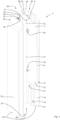
- FIG. 1 shows a side guide 20 of a fire protection closure 2.
- a guide rail 22 comprises a first guide rail part 72 and a second guide rail part 73, which are shown spaced apart from one another.
- the guide rail parts 72, 73 can be dismantled, for example, for maintenance purposes.
- a fire protection curtain 4 extends through a guide opening 24 into a guide channel 30.
- the guide channel 30 is in an assembled state between the first guide rail part 72 and the second guide rail part 73.
- a sealing groove 70 and an element guide area 42 are incorporated into the guide channel 30 in each of the first guide rail part 72 and the second guide rail part 73, but this is only indicated by reference numerals on one of the guide rail parts 72, 73.
- the guide area 42 comprises an element guide channel 44.
- the element guide area 42 there are a plurality of surface areas of the guide channel 30, such as a first boundary surface 46, a second boundary surface 47 opposite the first boundary surface 46.
- a first sliding surface 50 is located between the two boundary surfaces 46, 47, with a second sliding surface 51 being present opposite the first sliding surface 50.
- a first guide element 32 and a second guide element 33 are attached to the fire protection curtain 4 in a side area 6.
- the guide elements 32, 33 are located on cover layers 10, 12 of the curtain 4. Between a first curtain surface 10 and a second curtain surface 12 there is an inner area as a middle layer 14 of the curtain 4, which is not perforated in the area of the guide elements 32, 33.
- the guide rail 22 extends from an insertion end 26 to a terminal end 27.
- the guide elements 32, 33 are located in the element guide area 42, as shown.
- An end area 8 of the fire protection curtain 4 is also located in the element guide area 42.
- the guide rail parts 72, 73 can be screwed together via a web 90.
- a pin 25 on the insertion end 26 facilitates connection of the guide rail 22 to a curtain box (not shown).
- the fire protection closure 2 is located with a Anchoring 96 mounted on a wall 94.
- the first guide rail part 72 is fixed to the wall 94 in the area of the web 90 with the wall dowel 96.
- the side guide 20 is thus arranged in a fixed position.
- the second guide rail part 73 is screwed to the first guide rail part 72 in the web areas 90, 90' with the wood screw 82, so that the guide channel 30 is present in the composite guide rail 22. Segments such as the element guide area 42 and a guide gap 60 can be distinguished on the guide channel 30.
- the first curtain surface 10, the second curtain surface 12 and the middle layer 14 extend through the guide gap 60.
- Rolling elements such as the rolling element 38, which are mounted on the cover layer 12, for example, with the aid of a fastening collar 39, are arranged in front of the cover layers 10, 12.
- a first guide element part 36 is connected to the first curtain surface 10 and a second guide element part 37 is connected to the second curtain surface 12, which together belong to the first guide element 32.
- the first guide element part 36 can roll on the second boundary surface 47.
- the first guide element part 36 can run on a first running surface region 54. In the element guide region 42, the first guide element part 36 can slide along the first sliding surface 50.
- the second guide element part 37 can run on the second boundary surface 47.
- the second guide element part 37 can roll on the second running surface region 55.
- the second guide element part 37 can slide along the second sliding surface 51 in the guide channel 30.
- the guide gap 60 is narrowed by a first guide bulge 62 and a second guide bulge 63.
- Curtain sliding surfaces 66, 67 are located on the guide recesses 62, 63 marked as an example on the second guide rail part 73.
- Guide recesses and curtain sliding surfaces (without reference numerals) are also present on the first guide rail part 72.
- the sealing groove 70 is incorporated between the guide recesses 62, 63 and is used to attach a swellable sealing strip.
- a bearing hole 84 is let in, which provides a seat for an expandable locking pin 86.
- At least one locking pin, such as the locking pin 86 is present and forms a thermally activated locking device. In the event of a fire, a position of the curtain surface 10 can thus be secured against slipping.
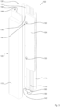
- FIG. 3 Another embodiment of a fire protection closure 102 is shown in Figure 3 shown in detail, which comprises a side guide 120.
- the side guide 120 is formed by a first guide rail part 172 and a second guide rail part 173.
- a fire protection curtain 104 can be moved along the guide rail parts 172, 173 on guide elements 132, 133.
- the guide elements 132, 133 can be arranged in a Element guide area 142 slide along a guide channel 130.
- the fire protection curtain is additionally guided in a guide gap 160 and supported by the frame in the guide gap 160 in a transverse direction to the direction of movement.
- the guide gap 160 can be completely closed in the event of a fire.
- the first guide rail part 172 and the second guide rail part 173 can be screwed together at assembly points, such as the assembly point 176, which are located along the web areas 190, 190 ⁇ .
- assembly points 176 which are located along the web areas 190, 190 ⁇ .
- an assembly groove 188 of the guide rail 122 is incorporated into the guide rail parts 172, 173.
- a mounting bracket 192 is attached to a wall 194 with an anchor 196.
- Rock wool is inserted between the side guide 120 and the wall 194 as a leveling compound 198 in order to seal off any unevenness in the wall in a connection area of the side guide 120.
- a first guide rail part 172 was screwed to the mounting bracket 192 with a wood screw 182'.
- a second wood screw 182 fastens the first guide rail part 172 and the second guide rail part 173 to one another. This means that the side guide can be installed in just a few steps.
- the first guide element 132 which has a clamp element 140
- the clamp element 140 connects two guide element parts.
- the clamp element 140 serves to enclose, in particular clamp, an end region 108 of the fire curtain 104 (see Figure 3 ) for fixing the guide element 132.
- a swelling tape 171 is glued into the sealing groove 170 of the guide rail 122, which is in a Figure 4 shown, cold initial state is so thin that it does not protrude from the sealing groove 170.
- the expansion tape 171 comprises an insulating material.
- the expansion tape is approximately 10 mm wide and 1.5 mm thick and can swell up to eight times its volume at a temperature of up to 150 °C.
- the side guide 120 offers simple and quick installation options, whereby installation directions other than those shown are also possible.
- the side guide 120 offers a high degree of sealing security for the fire protection closure 102, in particular due to an opposite expansion tape arrangement 171, 171'.
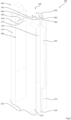
- a particularly simple and compact, one-piece guide rail 222 for a Side guide 220 of a fire protection closure 202 shows Figure 5 .
- the guide rail 222 can even be machined from a single piece of wood or wooden beam in a single machine pass, e.g. by milling, planing or sawing or a combination thereof.
- the fire protection curtain 204 was introduced into the guide channel 230 through the insertion opening 228.
- the dimensions of the internal guide elements do not allow the fire protection curtain 204 to exit through a guide opening 224.
- An element guide area 242 and a guide gap 260 are arranged adjacent to one another in the guide channel 230.
- the guide gap 260 comprises two first guide bulges 262, 262 ⁇ and two second guide bulges 263, 263 ⁇ .
- a first sealing groove 270 is located between the first guide bulges 262, 262 ⁇ .
- the first sealing groove 270 is located opposite a second sealing groove 270 ⁇ .
- the first guide bulges 262, 262 ⁇ are located opposite each other on both sides of the guide gap 260.
- the second guide bulges 263, 263 ⁇ are incorporated in a corresponding arrangement in the side guide 220. This allows the fire protection curtain 204 to slide particularly precisely.
- a section of a fire protection closure 302 in Figure 6 shows a modularly constructed side guide 320, which comprises a first guide rail module 372, a second guide rail module 373 and a third guide rail module 374.
- the three guide rail modules 372, 373, 374 together form a guide rail 322 for guiding a fire curtain 304.
- the third guide rail module 374 can also be referred to as a web 390 according to one aspect of the connection.
- the web 390 has mounting points, such as a first mounting point 376 and a second mounting point 377, which are each present in pairs and have a predetermined distance 380 from one another.
- the mounting points of the web 390 are assigned mounting points on the other guide rail modules 372, 373, such as the mounting point 376', for screwing them together.
- the second mounting point 377 is used accordingly. This allows a width of a guide opening 324 to be determined, which is located between the first guide rail module 372 and the second guide rail module 373.
- the distance 380 is also reflected in the respective widths of the guide channel 330 or a width of an element guide area 342, a width of a guide gap 360 and in particular a distance of the bulges, such as the bulges 362, 363, between the first guide rail module 372 and the second guide rail module 373.
- a pin 325 is advantageously incorporated into the first guide rail module 372 and the second guide rail module 373 or the third guide rail module 374.
- a modular design offers even more Possible applications of a lateral guide according to the invention.
Landscapes
- Health & Medical Sciences (AREA)
- Public Health (AREA)
- Business, Economics & Management (AREA)
- Emergency Management (AREA)
- Operating, Guiding And Securing Of Roll- Type Closing Members (AREA)
Claims (16)
- Guidage latéral (20, 120, 220, 320) pour une fermeture coupe-feu (2, 102, 202, 302), en particulier pour une protection totale contre le feu, dans lequel le guidage latéral (20, 120, 220, 320) est un guidage latéral coupe-feu (20, 120, 220, 320),qui présente au moins un rail de guidage (22, 122, 222, 322),dans lequel le guidage latéral (20, 120, 220, 320) permet une mobilité de la fermeture coupe-feu (2, 102, 202, 302) le long du rail de guidage (22, 122, 222, 322),dans lequel le guidage latéral (20, 120, 220, 320) possède une forme allongée du type bloc,dans lequel le rail de guidage (22, 122, 222, 322) est entièrement constitué d'un bois,dans lequel le bois est un bois lissé traité en surface,de sorte que le guidage latéral (20, 120, 220, 320) présente une résistance au feu pendant au moins 30 minutes,et dans lequel le rail de guidage (22, 122, 222, 322) représente les faces d'un canal de guidage (30, 130, 230, 330) délimité au moins sur quatre côtés etle canal de guidage (30, 130, 230, 330) est conçu pour un(e) réception et guidage le long du rail de guidage (22, 122, 222, 322) d'au moins un élément de guidage (32, 33, 132, 133) pouvant se déplacer sur une surface du rail de guidage (22, 122, 222, 322) et relié à un rideau coupe-feu (4, 104, 204, 304) de la fermeture coupe-feu (2, 102, 202, 302).
- Guidage latéral (20, 120, 220, 320) selon la revendication 1,
dans lequel le guidage latéral permet une possibilité de déplacement de la fermeture coupe-feu (2, 102, 202, 302) dans la direction latérale le long du rail de guidage (22, 122, 222, 322) . - Guidage latéral (20, 120, 220, 320) selon la revendication 1 ou 2,dans lequel le rail de guidage (22, 122, 222, 322) présente une pluralité de surfaces intérieures, qui forment le canal de guidage (30, 130, 230, 330), en particulier exempt de moyens de fixation,parmi lesquelles de préférence une surface intérieure forme une surface le long de laquelle l'élément de guidage (32, 33, 132, 133) est mobile,dans lequel le canal de guidage (30, 130, 230, 330) le long d'une étendue longitudinale de rail de guidage débouche longitudinalement du rail de guidage (22, 122, 222, 322) par une ouverture de guidage (24, 224, 324).
- Guidage latéral (20, 120, 220, 320) selon l'une quelconque des revendications précédentes,dans lequel le canal de guidage (30, 130, 230, 330) présente au moins une première surface de délimitation (46), qui est conformée également comme une surface de roulement (46) pour l'élément de guidage (32, 33, 132, 133),dans lequel de préférence la première surface de délimitation (46) convient à la réception d'une force de traction.
- Guidage latéral (20, 120, 220, 320) selon la revendication 4,dans lequel le canal de guidage (30, 130, 230, 330) présente au moins une deuxième surface de délimitation (47), qui est définie également comme une surface de roulement (47) pour au moins un des éléments de guidage (32, 33, 132, 133),dans lequel de préférence la deuxième surface de délimitation (47) est adaptée à recevoir une force de cisaillement.
- Guidage latéral (20, 120, 220, 320) selon l'une quelconque des revendications précédentes,dans lequel le canal de guidage (30, 130, 230, 330) présente au moins une surface de glissement (50, 51),qui se trouve de préférence entre une première surface de délimitation (46) et une deuxième surface de délimitation (47) .
- Guidage latéral (20, 120, 220, 320) selon l'une quelconque des revendications précédentes,dans lequel le canal de guidage (30, 130, 230, 330) présente une fente de guidage (60, 160, 260, 360),qui est adjacente à une rigole de guidage d'éléments (44) etqui est adjacente à une délimitation du canal de guidage (30, 130, 230, 330) sur un premier côté du canal de guidage (30, 130, 230, 330),dans lequel en particulier la fente de guidage (60, 160, 260, 360) s'étend à partir d'une première surface de délimitation (46), de préférence entre une première zone de surface de roulement (54) et une deuxième zone de surface de roulement (55) d'une première surface de délimitation (46) en deux parties.
- Guidage latéral (20, 120, 220, 320) selon l'une quelconque des revendications précédentes,dans lequel le canal de guidage (30, 130, 230, 330) présente au moins un premier renflement de guidage (62, 262, 262', 362),qui forme une surface de glissement d'élément de fermeture (66, 67).
- Guidage latéral (20, 120, 220, 320) selon la revendication 8,dans lequel le canal de guidage (30, 130, 230, 330) présente un deuxième renflement de guidage (63, 263, 263', 363) s'étendant parallèlement au premier renflement de guidage (62, 262, 262', 362),qui est présent en particulier de manière plus espacée d'une surface de délimitation (46, 47) que le premier renflement de guidage (62, 262, 262', 362), etdans lequel de préférence le premier renflement de guidage (62, 262, 262', 362) offre une zone de fente de guidage pour la fermeture coupe-feu (2, 102, 202, 302) plus étroite que le deuxième renflement de guidage (63, 263, 263', 363) .
- Guidage latéral (20, 120, 220, 320) selon l'une quelconque des revendications précédentes,
dans lequel le canal de guidage (30, 130, 230, 330) comprend au moins une rainure d'étanchéité (70, 170, 270, 270'), en particulier pour un matériau d'étanchéité (171, 171') pouvant gonfler thermiquement, dans lequel le matériau d'étanchéité (171, 171') sert à l'étanchéification sur la fermeture coupe-feu (2, 102, 202, 302). - Guidage latéral (20, 120, 220, 320) selon l'une quelconque des revendications précédentes,dans lequel le rail de guidage (22, 122, 222, 322) est constitué, de préférence entièrement, d'un bois dur, tel que du chêne, ou d'un bois de construction,dans lequel de préférence le rail de guidage (22, 122, 222, 322) est un rail de guidage (22, 122, 322) en plusieurs parties, etdans lequel en particulier deux ou trois parties de rail de guidage (72, 73, 172, 173, 372, 373, 374) délimitent le canal de guidage (30, 130, 230, 330).
- Guidage latéral (20, 120) selon l'une quelconque des revendications précédentes,
dans lequel le guidage latéral (20, 120) comprend au moins une broche d'arrêt (86) pouvant se déployer à travers un matériau de gonflement thermique à partir d'un trou de palier (84) du rail de guidage (22, 122) jusque dans une zone de la fermeture coupe-feu (2, 102). - Guidage latéral (20, 120, 220, 320) selon l'une quelconque des revendications précédentes,dans lequel le rail de guidage (22, 122, 222, 322) présente une extrémité d'introduction (26), qui est réalisée comme un tourillon (25, 325) pouvant être raccordé à une suspension de rideau ou un caisson de fermeture,dans lequel en particulier une ouverture d'introduction (28, 228) du rail de guidage (22, 122, 222, 322) subit un agrandissement cunéiforme avec un raccordement.
- Guidage latéral (20, 120, 220, 320) selon l'une quelconque des revendications précédentes,dans lequel le rail de guidage (122) présente une rainure de montage (188),qui s'étend au moins par endroits le long du canal de guidage (30, 130, 230, 330),dans lequel un élément jointif (90, 90', 190, 190', 390), qui sépare la rainure de montage (188) du canal de guidage (30, 130, 230, 330), en particulier sur une longueur totale du rail de guidage (122), est présent de préférence entre la rainure de montage (188) et le canal de guidage (30, 130, 230, 330) .
- Guidage latéral (320) selon l'une quelconque des revendications précédentes,dans lequel le rail de guidage (322) est de conception modulaire,dans lequel un premier module de rail de guidage (372) sert à adapter le rail de guidage (322) à une épaisseur d'une fermeture coupe-feu (302) à l'aide d'au moins un deuxième module de rail de guidage (373), en échange de quoi en particulier le premier module de rail de guidage (372) présente au moins deux points de montage (376, 376', 377), de préférence quatre points de montage, qui déterminent une disposition d'un deuxième module de rail de guidage (373) ou un écart (380) de deux deuxièmes modules de rail de guidage (373, 374) sur le premier module de rail de guidage (372).
- Fermeture coupe-feu (2, 102, 202, 302),qui comprend au moins un rideau coupe-feu (4, 104, 204, 304) pouvant être distribué à plat,dans laquelle le rideau coupe-feu (4, 104, 204, 304) est guidé au moins des deux côtés par au moins un guidage latéral (20, 120, 220, 320),dans laquelle le rideau coupe-feu (4, 104, 204, 304) présente des éléments de guidage (32, 33, 132, 133) sur au moins un côté de rideau (6),caractérisée en ce queau moins l'un des guidages latéraux (20, 120, 220, 320) est réalisé selon l'une quelconque des revendications précédentes,dans laquelle les éléments de guidage (32, 33, 132, 133) sont réalisés pour faciliter un guidage du rideau coupe-feu (4, 104, 204, 304), et le guidage est présent le long d'au moins un rail de guidage (22, 122, 222, 322).
Applications Claiming Priority (1)
| Application Number | Priority Date | Filing Date | Title |
|---|---|---|---|
| DE202016100779.8U DE202016100779U1 (de) | 2016-02-16 | 2016-02-16 | Seitenführung für einen Brandschutzverschluss und ein mit Seitenführungen ausgestatteter Brandschutzverschluss |
Publications (3)
| Publication Number | Publication Date |
|---|---|
| EP3207958A1 EP3207958A1 (fr) | 2017-08-23 |
| EP3207958C0 EP3207958C0 (fr) | 2025-01-08 |
| EP3207958B1 true EP3207958B1 (fr) | 2025-01-08 |
Family
ID=58043894
Family Applications (1)
| Application Number | Title | Priority Date | Filing Date |
|---|---|---|---|
| EP17155670.7A Active EP3207958B1 (fr) | 2016-02-16 | 2017-02-10 | Guidage latéral pour une fermeture coupe-feu et fermeture coupe-feu équipée de guidage latéraux |
Country Status (2)
| Country | Link |
|---|---|
| EP (1) | EP3207958B1 (fr) |
| DE (1) | DE202016100779U1 (fr) |
Families Citing this family (1)
| Publication number | Priority date | Publication date | Assignee | Title |
|---|---|---|---|---|
| JP2020169484A (ja) * | 2019-04-03 | 2020-10-15 | 学校法人 中村産業学園 | 止水装置および止水方法 |
Citations (2)
| Publication number | Priority date | Publication date | Assignee | Title |
|---|---|---|---|---|
| DE4236548A1 (de) * | 1992-10-29 | 1994-05-05 | Mauderer Leichtmetallbau | Innenjalousie für ein Dachfenster |
| DE202007013061U1 (de) * | 2007-09-18 | 2007-12-13 | Holzbau Schmid Gmbh & Co. Kg | Brandschutzrolladen |
Family Cites Families (14)
| Publication number | Priority date | Publication date | Assignee | Title |
|---|---|---|---|---|
| FR1260823A (fr) | 1960-04-08 | 1961-05-12 | Rideau d'obscurcissement | |
| DE1179340B (de) | 1963-01-25 | 1964-10-08 | Rudolf Stoerzbach | Vorhangschiene |
| DE29922593U1 (de) | 1999-12-23 | 2000-04-13 | Stöbich Brandschutz GmbH & Co. KG, 38644 Goslar | Schutzvorhang-Seitenführung |
| GB0313587D0 (en) * | 2003-06-12 | 2003-07-16 | Cooper Andrew P | Barrier |
| DE202004018977U1 (de) | 2004-12-08 | 2005-02-10 | Stöbich Brandschutz GmbH & Co. KG | Dichtungsanordnung für einen Brand- bzw. Rauchvorhang |
| US20060151132A1 (en) | 2005-01-13 | 2006-07-13 | Augustus Scalfani | Hurricane curtain |
| DE102008023646A1 (de) | 2008-05-15 | 2010-06-10 | Kgg Brandschutzsysteme Gmbh | Sicherheitsvorhangsystem |
| BE1019388A3 (nl) * | 2009-06-26 | 2012-06-05 | Hoefnagels Special Systems B V | Brandvertragend rolgordijn. |
| US8622112B2 (en) | 2009-09-15 | 2014-01-07 | Storm Solutions, Inc. | Retractable, low-profile storm shield systems and methods |
| DE202013100100U1 (de) | 2013-01-09 | 2013-02-19 | Wigger Fenster + Fassaden GmbH & Co. KG | Holzrahmen mit Rollladenführung |
| DE102013216866A1 (de) * | 2013-08-23 | 2015-02-26 | Bernd Heydebreck | Rollladen, Brandschutzvorhang sowie Brandschutzrollladen |
| DE202015100372U1 (de) * | 2014-01-29 | 2015-04-30 | Hörmann KG Amshausen | Führungsschiene für Rauch- und/oder Brandschutzvorhang sowie damit versehener Rauch- und/oder Brandschutzabschluss |
| SG10201403775YA (en) * | 2014-07-01 | 2016-02-26 | Gliderol Doors S Pte Ltd | Insulated fire panel shutter |
| DE102015117548B4 (de) | 2015-10-15 | 2023-12-14 | Kgg Brandschutzsysteme Gmbh | Verschlussvorrichtung und Verfahren zur Montage einer Verschlussvorrichtung für eine Bauwerksöffnung |
-
2016
- 2016-02-16 DE DE202016100779.8U patent/DE202016100779U1/de not_active Expired - Lifetime
-
2017
- 2017-02-10 EP EP17155670.7A patent/EP3207958B1/fr active Active
Patent Citations (2)
| Publication number | Priority date | Publication date | Assignee | Title |
|---|---|---|---|---|
| DE4236548A1 (de) * | 1992-10-29 | 1994-05-05 | Mauderer Leichtmetallbau | Innenjalousie für ein Dachfenster |
| DE202007013061U1 (de) * | 2007-09-18 | 2007-12-13 | Holzbau Schmid Gmbh & Co. Kg | Brandschutzrolladen |
Also Published As
| Publication number | Publication date |
|---|---|
| EP3207958C0 (fr) | 2025-01-08 |
| DE202016100779U1 (de) | 2017-05-17 |
| EP3207958A1 (fr) | 2017-08-23 |
Similar Documents
| Publication | Publication Date | Title |
|---|---|---|
| EP0169918A1 (fr) | Fenêtre isolante thermiquement | |
| EP3401496A1 (fr) | Rail de guidage pour une installation de protection solaire et installation de protection solaire correspondante | |
| DE102015113453A1 (de) | Einbausatz für einen französischen Balkon | |
| EP1273749B1 (fr) | Elément coulissant | |
| EP3207958B1 (fr) | Guidage latéral pour une fermeture coupe-feu et fermeture coupe-feu équipée de guidage latéraux | |
| DE20304015U1 (de) | Vorrichtung zum Verbessern der wärmetechnischen Eigenschaften von lichtdurchlässigen Gebäudeteilen | |
| EP2492432A2 (fr) | Caisson de store ou de store à lamelles ainsi qu'insert d'isolation thermique associé | |
| DE202004021567U1 (de) | Wärmedämmendes Element für Hohlräume | |
| DE10126729B4 (de) | Rollladenvorrichtung | |
| EP0918127B1 (fr) | Châssis de porte et dispositif de montage | |
| EP1106772A1 (fr) | Coffre d'attachement de volet roulant | |
| DE202015106143U1 (de) | Rolladenelement für die Abdeckung einer Gebäudeöffnung | |
| DE102015102302A1 (de) | Rollraumverkleidung für einen Rollladenkasten | |
| DE202009016152U1 (de) | Zarge | |
| DE102017118275B4 (de) | Torvorrichtung und diese enthaltende Toranordnung | |
| EP2159363B1 (fr) | Paroi d'immeuble isolée thermiquement dotée d'une porte et/ou d'une fenêtre | |
| DE19944350A1 (de) | Blendrahmenprofil für Fenster für zweischalige Mauerwerke | |
| DE102019122600A1 (de) | Vorsatzschalenanordnung für ein Verbundfenster sowie Verbundfenstersystem aufweisend die Vorsatzschalenanordnung | |
| DE4303573A1 (de) | Dichtungssystem mit Primär- und Sekundärdichtung | |
| EP1878866B1 (fr) | Elément pour intrados | |
| DE8327232U1 (de) | Jalousie zum abdecken einer wandoeffnung | |
| DE102016111410A1 (de) | Mittelstütze für eine Gebäudeöffnung mit großer lichter Breite | |
| DE102016115424B4 (de) | Fenster | |
| DE4336069C2 (de) | Rolladenkonstruktion | |
| EP4446556B1 (fr) | Dispositif d'ombrage d'une ouverture de bâtiment et rail de guidage latéral associé |
Legal Events
| Date | Code | Title | Description |
|---|---|---|---|
| PUAI | Public reference made under article 153(3) epc to a published international application that has entered the european phase |
Free format text: ORIGINAL CODE: 0009012 |
|
| STAA | Information on the status of an ep patent application or granted ep patent |
Free format text: STATUS: THE APPLICATION HAS BEEN PUBLISHED |
|
| AK | Designated contracting states |
Kind code of ref document: A1 Designated state(s): AL AT BE BG CH CY CZ DE DK EE ES FI FR GB GR HR HU IE IS IT LI LT LU LV MC MK MT NL NO PL PT RO RS SE SI SK SM TR |
|
| AX | Request for extension of the european patent |
Extension state: BA ME |
|
| STAA | Information on the status of an ep patent application or granted ep patent |
Free format text: STATUS: REQUEST FOR EXAMINATION WAS MADE |
|
| 17P | Request for examination filed |
Effective date: 20180220 |
|
| RBV | Designated contracting states (corrected) |
Designated state(s): AL AT BE BG CH CY CZ DE DK EE ES FI FR GB GR HR HU IE IS IT LI LT LU LV MC MK MT NL NO PL PT RO RS SE SI SK SM TR |
|
| STAA | Information on the status of an ep patent application or granted ep patent |
Free format text: STATUS: EXAMINATION IS IN PROGRESS |
|
| 17Q | First examination report despatched |
Effective date: 20180425 |
|
| GRAP | Despatch of communication of intention to grant a patent |
Free format text: ORIGINAL CODE: EPIDOSNIGR1 |
|
| STAA | Information on the status of an ep patent application or granted ep patent |
Free format text: STATUS: GRANT OF PATENT IS INTENDED |
|
| INTG | Intention to grant announced |
Effective date: 20240611 |
|
| GRAJ | Information related to disapproval of communication of intention to grant by the applicant or resumption of examination proceedings by the epo deleted |
Free format text: ORIGINAL CODE: EPIDOSDIGR1 |
|
| STAA | Information on the status of an ep patent application or granted ep patent |
Free format text: STATUS: EXAMINATION IS IN PROGRESS |
|
| GRAP | Despatch of communication of intention to grant a patent |
Free format text: ORIGINAL CODE: EPIDOSNIGR1 |
|
| STAA | Information on the status of an ep patent application or granted ep patent |
Free format text: STATUS: GRANT OF PATENT IS INTENDED |
|
| INTC | Intention to grant announced (deleted) | ||
| INTG | Intention to grant announced |
Effective date: 20240826 |
|
| GRAS | Grant fee paid |
Free format text: ORIGINAL CODE: EPIDOSNIGR3 |
|
| GRAA | (expected) grant |
Free format text: ORIGINAL CODE: 0009210 |
|
| STAA | Information on the status of an ep patent application or granted ep patent |
Free format text: STATUS: THE PATENT HAS BEEN GRANTED |
|
| AK | Designated contracting states |
Kind code of ref document: B1 Designated state(s): AL AT BE BG CH CY CZ DE DK EE ES FI FR GB GR HR HU IE IS IT LI LT LU LV MC MK MT NL NO PL PT RO RS SE SI SK SM TR |
|
| REG | Reference to a national code |
Ref country code: GB Ref legal event code: FG4D Free format text: NOT ENGLISH |
|
| REG | Reference to a national code |
Ref country code: CH Ref legal event code: EP |
|
| REG | Reference to a national code |
Ref country code: DE Ref legal event code: R096 Ref document number: 502017016642 Country of ref document: DE |
|
| REG | Reference to a national code |
Ref country code: IE Ref legal event code: FG4D Free format text: LANGUAGE OF EP DOCUMENT: GERMAN |
|
| U01 | Request for unitary effect filed |
Effective date: 20250203 |
|
| U07 | Unitary effect registered |
Designated state(s): AT BE BG DE DK EE FI FR IT LT LU LV MT NL PT RO SE SI Effective date: 20250207 |
|
| U20 | Renewal fee for the european patent with unitary effect paid |
Year of fee payment: 9 Effective date: 20250214 |
|
| PGFP | Annual fee paid to national office [announced via postgrant information from national office to epo] |
Ref country code: CH Payment date: 20250301 Year of fee payment: 9 |
|
| PG25 | Lapsed in a contracting state [announced via postgrant information from national office to epo] |
Ref country code: RS Free format text: LAPSE BECAUSE OF FAILURE TO SUBMIT A TRANSLATION OF THE DESCRIPTION OR TO PAY THE FEE WITHIN THE PRESCRIBED TIME-LIMIT Effective date: 20250408 |
|
| PG25 | Lapsed in a contracting state [announced via postgrant information from national office to epo] |
Ref country code: PL Free format text: LAPSE BECAUSE OF FAILURE TO SUBMIT A TRANSLATION OF THE DESCRIPTION OR TO PAY THE FEE WITHIN THE PRESCRIBED TIME-LIMIT Effective date: 20250108 |
|
| PG25 | Lapsed in a contracting state [announced via postgrant information from national office to epo] |
Ref country code: ES Free format text: LAPSE BECAUSE OF FAILURE TO SUBMIT A TRANSLATION OF THE DESCRIPTION OR TO PAY THE FEE WITHIN THE PRESCRIBED TIME-LIMIT Effective date: 20250108 |
|
| PG25 | Lapsed in a contracting state [announced via postgrant information from national office to epo] |
Ref country code: NO Free format text: LAPSE BECAUSE OF FAILURE TO SUBMIT A TRANSLATION OF THE DESCRIPTION OR TO PAY THE FEE WITHIN THE PRESCRIBED TIME-LIMIT Effective date: 20250408 Ref country code: IS Free format text: LAPSE BECAUSE OF FAILURE TO SUBMIT A TRANSLATION OF THE DESCRIPTION OR TO PAY THE FEE WITHIN THE PRESCRIBED TIME-LIMIT Effective date: 20250508 |
|
| PG25 | Lapsed in a contracting state [announced via postgrant information from national office to epo] |
Ref country code: HR Free format text: LAPSE BECAUSE OF FAILURE TO SUBMIT A TRANSLATION OF THE DESCRIPTION OR TO PAY THE FEE WITHIN THE PRESCRIBED TIME-LIMIT Effective date: 20250108 |
|
| PG25 | Lapsed in a contracting state [announced via postgrant information from national office to epo] |
Ref country code: GR Free format text: LAPSE BECAUSE OF FAILURE TO SUBMIT A TRANSLATION OF THE DESCRIPTION OR TO PAY THE FEE WITHIN THE PRESCRIBED TIME-LIMIT Effective date: 20250409 |
|
| PG25 | Lapsed in a contracting state [announced via postgrant information from national office to epo] |
Ref country code: SM Free format text: LAPSE BECAUSE OF FAILURE TO SUBMIT A TRANSLATION OF THE DESCRIPTION OR TO PAY THE FEE WITHIN THE PRESCRIBED TIME-LIMIT Effective date: 20250108 |
|
| PG25 | Lapsed in a contracting state [announced via postgrant information from national office to epo] |
Ref country code: MC Free format text: LAPSE BECAUSE OF FAILURE TO SUBMIT A TRANSLATION OF THE DESCRIPTION OR TO PAY THE FEE WITHIN THE PRESCRIBED TIME-LIMIT Effective date: 20250108 |
|
| PG25 | Lapsed in a contracting state [announced via postgrant information from national office to epo] |
Ref country code: CZ Free format text: LAPSE BECAUSE OF FAILURE TO SUBMIT A TRANSLATION OF THE DESCRIPTION OR TO PAY THE FEE WITHIN THE PRESCRIBED TIME-LIMIT Effective date: 20250108 |
|
| PG25 | Lapsed in a contracting state [announced via postgrant information from national office to epo] |
Ref country code: SK Free format text: LAPSE BECAUSE OF FAILURE TO SUBMIT A TRANSLATION OF THE DESCRIPTION OR TO PAY THE FEE WITHIN THE PRESCRIBED TIME-LIMIT Effective date: 20250108 |
|
| PLBE | No opposition filed within time limit |
Free format text: ORIGINAL CODE: 0009261 |
|
| STAA | Information on the status of an ep patent application or granted ep patent |
Free format text: STATUS: NO OPPOSITION FILED WITHIN TIME LIMIT |
|
| REG | Reference to a national code |
Ref country code: CH Ref legal event code: L10 Free format text: ST27 STATUS EVENT CODE: U-0-0-L10-L00 (AS PROVIDED BY THE NATIONAL OFFICE) Effective date: 20251119 |
|
| 26N | No opposition filed |
Effective date: 20251009 |
|
| PG25 | Lapsed in a contracting state [announced via postgrant information from national office to epo] |
Ref country code: IE Free format text: LAPSE BECAUSE OF NON-PAYMENT OF DUE FEES Effective date: 20250210 |
|
| REG | Reference to a national code |
Ref country code: CH Ref legal event code: U11 Free format text: ST27 STATUS EVENT CODE: U-0-0-U10-U11 (AS PROVIDED BY THE NATIONAL OFFICE) Effective date: 20260303 |
|
| U20 | Renewal fee for the european patent with unitary effect paid |
Year of fee payment: 10 Effective date: 20260227 |
|
| PGFP | Annual fee paid to national office [announced via postgrant information from national office to epo] |
Ref country code: GB Payment date: 20260324 Year of fee payment: 10 |