EP3208013A1 - Procédé de moulage d'un élément structurel ayant une géométrie complexe à l'aide d'un moule segmenté - Google Patents
Procédé de moulage d'un élément structurel ayant une géométrie complexe à l'aide d'un moule segmenté Download PDFInfo
- Publication number
- EP3208013A1 EP3208013A1 EP17153442.3A EP17153442A EP3208013A1 EP 3208013 A1 EP3208013 A1 EP 3208013A1 EP 17153442 A EP17153442 A EP 17153442A EP 3208013 A1 EP3208013 A1 EP 3208013A1
- Authority
- EP
- European Patent Office
- Prior art keywords
- mold
- casting
- segments
- component
- lost
- Prior art date
- Legal status (The legal status is an assumption and is not a legal conclusion. Google has not performed a legal analysis and makes no representation as to the accuracy of the status listed.)
- Granted
Links
Images





Classifications
-
- B—PERFORMING OPERATIONS; TRANSPORTING
- B22—CASTING; POWDER METALLURGY
- B22C—FOUNDRY MOULDING
- B22C9/00—Moulds or cores; Moulding processes
Definitions
- the present invention relates to a method for casting a component of complex geometry, in particular by die casting, in which a casting mold is used, of which at least one molded part is formed as a lost shape.
- a positively shaped model of the coil is produced, for example, from a wax or a polymer, which is subsequently filled with a non-solid investment material is poured, which then sets and hardens.
- the model is melted from the solidified embedding mass and the investment material optionally additionally fired in order to achieve maximum strength and stability. In this case, possibly remaining or not melted residues of the model burn almost completely.
- the mold filling of the resulting cavity takes place in the investment with molten metal. After solidification of the molten metal, the investment is then destroyed to expose the casting.
- the casting-technical production of the positively shaped model - usually by injection molding with wax in metallic permanent molds - represents a technological challenge.
- the EP 2387135 A2 describes a method for producing an electrical coil in casting technique, in which a negative mold containing the coil geometry is used as a lost form or as a permanent mold. As a molding material for the lost form here sand or an embedding mass is proposed. The document also mentions the use of multi-part segments, which are added before or during the forming process for producing the negative mold, but without going into detail here.
- the DE 102012006572 A1 describes a method in which initially a lost mold is produced as a block mold and then inserted as a mold insert in permanent metal molds to produce the component by die casting.
- the molding material used for the lost mold is a ceramic investment material.
- the surface quality of the manufactured component is very important.
- a smooth, error-free or low-defect surface is required for the subsequent application of a homogeneous electrical insulation coating.
- an insulation coating on the cast electrical coil so-called.
- Edge effect is to be avoided, which leads to a non-homogeneous layer formation of the coating at the edges of the coil.
- an edge rounding must be carried out which is carried out as a post-processing of the cast part and thus causes additional expenditure.
- the object of the present invention is to provide a method for casting a component of complex geometry, in which the component with high surface quality is obtained.
- the method should be particularly suitable for the production of electrical coils and manage without draft angles of the mold used.
- a casting mold is used, of which at least one molding is designed as a lost mold.
- the at least one formed as a lost mold molding is made from a salt or a salt mixture.
- the one or more formed as a lost form moldings are preferably produced by casting, particularly preferably by die casting.
- the entire casting mold is completely manufactured as a lost mold.
- the mold is preferably composed of more than two stacked mold segments.
- several of the mold segments can be identical, i. as identical parts. This simplifies the production and also allows a corresponding scaling of the components to be produced, for example the number of coil turns using the example of an electrical coil without having to produce different casting molds for this purpose.
- the shape segments can also be individually varied or mixed.
- the mold segments are built up in a modular manner, in or put together and thus gradually build up a complete mold.
- the mold segments can be connected to each other, for example, via a groove-key combination or via a dowel pin connection.
- the segment design described above is not used as an entire casting mold, but as a mold insert for a permanent mold.
- the mold insert can pretend in one embodiment, the entire geometry of the component to be cast.
- the outer part of the mold, which defines the outer geometry of the component to be cast formed as a permanent mold and the inner part through the mold insert as a lost shape in the segmental design described above.
- the decomposition of the mold or the mold insert into individual mold segments allows flexible cost-effective production of complex components, which also have a high surface quality due to the use of salts or salt mixtures as a molding material for the lost form formed therefrom.
- Each mold segment is preferably designed without undercuts and can be manufactured according to simple production methods, preferably in turn with a casting process or sintering or pressing process.
- the mold segments have in the region of the cavity, which is filled to form the component with molten metal, no Entformungsschrägen.
- complex components with several plane-parallel, flat faces or turns - preferably in the geometry of electrical coils - are produced by casting with high quality.
- the filling of the composite mold can take place via an exposed cavity structure, if present.
- the mold segments have corresponding structures, so that after casting a sprue which can be used by casting technology results.
- an overflow or a ventilation system can be realized.
- the sprue is preferably carried out on the (short) side of the winding head. This serves to reduce the mechanical reworking.
- the composite form can, as already stated above, either used directly as a casting mold and filled with molten metal or used as a mold insert in a permanent mold and stabilized by the permanent mold.
- the individual mold segments can be designed so that an edge rounding is achieved in the case of inner component edges. A corresponding post-processing of the component is then no longer necessary.
- the mold segments can, for example, be dimensioned and manufactured such that they each define one turn of the coil.
- the inner and outer parts of the mold can be made to mesh with each other when making an electric coil. This avoids burrs on the inside of the coil turns and shifts them to the surface of these turns or into the area of the edge rounding.
- the proposed method can produce components with very complex geometries.
- the method makes it possible to realize edge rounding on the inside when using a permanent mold in conjunction with a mold insert as a lost molded part, the realization of edge rounding on the outside of the component in conjunction with the absence of draft angles in use a permanent form or of permanent mold elements and the absence of draft angles in combination with a targeted shift of burrs.
- lost moldings as lost cores or mold inserts no draft angles are needed.
- the method has cost advantages in complex systems, since in many embodiments, no complicated slide technology is required.
- FIG. 1 shows in the upper part of an example of an electric coil 10, as it can be cast with the proposed method.
- the lower part of the picture FIG. 1 shows only for illustration, the coil 10 again in exploded form to the individual turns 11 to recognize better.
- a mold insert for a permanent metal mold is used in the present example, which is formed from stacked lost mold segments.
- the individual mold segments 1 are produced from a salt or a salt mixture, preferably in a casting process (in particular pressure-assisted casting) or in a pressing or sintering process. Suitable techniques are those skilled in the art, for example. From the already mentioned DE 102012022331 A1 , known.
- the casting-technical production of these mold segments 1 from a salt or salt mixture a high surface quality of the segments is achieved, which is transferred to the turns of the electrical coil to be produced.
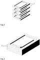
- FIG. 2 shows four such mold segments 1 , which are stacked on each other to form the mold insert. They can, for example, be connected to one another via a groove-feather key connection, not shown in the figure, in order to ensure correct and accurate assembly of the mold segments.
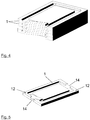
- FIG. 3 shows the stacked mold segments 1, FIG. 4 a section through this stack of mold segments.
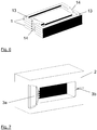
- FIG. 5 shows an example of a mold segment 1 having holes 12 for a dowel connection and side openings 14 for filling and / or venting.
- FIG. 6 again shows several stacked mold segments 1 with corresponding openings for filling and / or venting, in this example, dowel pins 13 can be seen.
- the composite mold segments 1 are then placed in a permanent mold 2 and filled with molten metal.
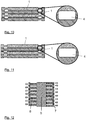
- An example of such a duration form 2 is in FIG. 7 shown.
- this gate and venting system 3a, 3b realized in the permanent form and may optionally be shown in the mold segments 1 (see. Fig. 5 and 6 ).
- FIG. 8 shows by way of example the permanent mold 2 with the mold segments 1 inserted therein.
- the cavity for the single turn for imaging the casting can be introduced only on one side in the mold segment 1, as in the example of FIG. 9 is shown.
- This figure shows, as well as the FIGS. 10 and 11 , Four stacked mold segments 1 in cross section, in which the cavity 4 for the formation of the coil turns 11 is clearly visible.
- the cavity 4 is introduced halfway into the top and bottom sides of the molding segment 1 in order to image the casting, as shown in FIG. 10 is shown by way of example.
- the burr formation is preferably targeted in the amount of Edge rounding of the casting shifted.
- the cavity 4 is introduced for imaging the casting with a larger proportion in the top and a smaller proportion in the bottom of the respective mold segment 1 with a corresponding shape offset. This is in FIG. 11 exemplified.
- Form segments 1 shown can also be used without external permanent mold, so that they form the complete mold.
- use of an external permanent form is advantageous for reasons of stability.
- the cavity for the casting production of the complex casting geometry is formed by the combination of permanent metal elements that define an outer shape of the casting with lost mold segments that define the internal geometry of the casting.
- FIG. 12 Here is a combination of an inner core 5 of lost core material (salt core) with external permanent mold elements 6, 7 shown, which are preferably made of two mold halves of the permanent mold or as a drawable slide elements.
- the exposed inner cavity 4 forms the casting.
- the in the FIG. 12 illustrated arrows indicate the structure of the permanent mold elements 6, 7 as a plurality of pullable slide elements.
- the permanent mold elements 6, 7 and the inner core 5 are so designed such that an edge rounding of the casting - on the inside shown in the inner lost core 5 and on the outside shown by the permanent mold elements 6, 7 - is obtained.
- the burr formation on the inside is determined in the amount of edge rounding. This is achieved by the positioning of the parting plane between the inner core 1 and permanent mold elements 6, 7, as in the FIG. 13 is shown. Burr formation on the outside is also selected in the amount of edge rounding produced by one-sided cavity formation in the permanent mold element, as shown in FIG FIG. 14 is illustrated.
- FIG. 15 shows an example in which the burr formation on the outside is positioned variably along the edge rounding. For this purpose, a two-sided formation of cavities in the permanent mold elements 6, 7 is selected.
- part of the cavity for the windings of the electrical coil is formed by the inner core 5.
- the cavity 4 is thereby proportionally formed by the inner core 1 and the permanent mold elements 6, 7, as shown in the FIG. 16 is shown.
- the permanent form is again performed with pullable slide elements.
- FIG. 17 shows the embodiment of FIG. 16 again with a detail.
- the edge rounding of the casting is on the inside by the lost core inside 1 and on the outside by the permanent mold elements 6, 7 shown. This creates no burr formation on the inside, but on the top or bottom of the conductor or winding surface. This burr formation is generated by the positioning of the parting plane between the inner core 5 and permanent mold element, as shown in FIG FIG. 17 is illustrated.
- FIG. 19 shows an embodiment in which the burr formation is positioned on the outside variable along the edge rounding. This is achieved by two-sided formation of cavities in the permanent mold elements 6, 7.
- the design of the FIG. 20 shows an inner core 1 of lost core material with raised ridges, which engage in the cavities of the outer permanent mold elements 6, 7.
- the permanent mold elements can in turn be made of two mold halves or - as in the present example - as a drawable slide elements.
- the exposed inner cavity 4 in turn forms the casting.
- the design of the FIG. 20 with the raised ridges on the inner core 5 has the advantage that the permanent mold elements 6, 7 engage in the lost core 5 (or vice versa) and thus support each other mutually.
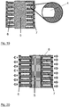
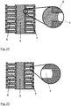
- FIG. 21 shows a development of this embodiment, in which the edge rounding of the casting on the inside is represented by the webs of the inner lost core 1 and on the outside by the permanent mold element 6, 7.
- a two-sided burr formation on the inside is produced by inserting the web 8 from the inner lost core 5 into the cavity of the permanent mold elements 6, 7.
- This burr formation can occur on the outside in the amount of the edge rounding, if a one-sided cavity formation in the permanent mold elements 6, 7 is selected.
- the burr formation can, as in FIG. 23 also be positioned variably along the edge rounding, if in the permanent mold elements 6, 7 a two-sided formation of cavities is selected.
- FIG. 24 shows finally an embodiment in which the lost core 5 has an integrated insert 9, which is integrated in the production of this lost core 5.
- the integrated insert 9 can be pulled out and destroys or damages the lost core to more easily demould it.
- This insert part 9 can be a mechanically stable element made of steel, iron, plastic, etc. or a wire, a rope or a fabric.
- the insert 9 is designed in such a way that when it is pulled out of the lost core 5 it leads to the damage or destruction of the core 5.
- the proposed method can be used with different casting techniques for metal casting, for example. Die casting, semi-solid process / thixocasting, low pressure casting, chill casting or metal injection molding.
- the casting mold is filled with a metallic melt, preferably with a melt of aluminum, copper, zinc, magnesium, steel, iron, cast iron and their alloys.
- the mold can be thermally heated prior to casting.
- the formed as a lost form moldings may be formed so that they are blasted or broken due to thermal and / or mechanical stresses after filling with the molten metal by the solidifying molten metal.
Landscapes
- Engineering & Computer Science (AREA)
- Mechanical Engineering (AREA)
- Molds, Cores, And Manufacturing Methods Thereof (AREA)
Applications Claiming Priority (1)
| Application Number | Priority Date | Filing Date | Title |
|---|---|---|---|
| DE102016202657.7A DE102016202657A1 (de) | 2016-02-22 | 2016-02-22 | Verfahren zum Gießen eines Bauteils komplexer Geometrie mit einer Gießform in Segmentbauweise |
Publications (2)
| Publication Number | Publication Date |
|---|---|
| EP3208013A1 true EP3208013A1 (fr) | 2017-08-23 |
| EP3208013B1 EP3208013B1 (fr) | 2023-08-16 |
Family
ID=57909512
Family Applications (1)
| Application Number | Title | Priority Date | Filing Date |
|---|---|---|---|
| EP17153442.3A Active EP3208013B1 (fr) | 2016-02-22 | 2017-01-27 | Procédé de moulage d'un élément structurel ayant une géométrie complexe à l'aide d'un moule segmenté |
Country Status (2)
| Country | Link |
|---|---|
| EP (1) | EP3208013B1 (fr) |
| DE (1) | DE102016202657A1 (fr) |
Cited By (8)
| Publication number | Priority date | Publication date | Assignee | Title |
|---|---|---|---|---|
| WO2019137969A1 (fr) * | 2018-01-12 | 2019-07-18 | Fraunhofer-Gesellschaft zur Förderung der angewandten Forschung e.V. | Dispositif de coulage ainsi que son procédé d'utilisation |
| WO2020058412A1 (fr) * | 2018-09-19 | 2020-03-26 | Fraunhofer-Gesellschaft zur Förderung der angewandten Forschung e.V. | Moule pour la fabrication de corps moulés hélicoïdaux |
| WO2020058397A1 (fr) * | 2018-09-19 | 2020-03-26 | Fraunhofer-Gesellschaft zur Förderung der angewandten Forschung e.V. | Fabrication d'une spirale, moule permanent pour une spirale et spirale associée |
| CN112004626A (zh) * | 2018-04-12 | 2020-11-27 | 弗劳恩霍夫应用研究促进协会 | 螺旋体的生产方法 |
| JPWO2020071532A1 (ja) * | 2018-10-04 | 2021-05-13 | 三菱電機株式会社 | コイル部品の製造方法、電気機械の製造方法、コイル部品及び電気機械 |
| EP4046727A1 (fr) | 2021-02-19 | 2022-08-24 | ae group ag | Procédé de fabrication d'une pièce coulée et moteur électrique |
| WO2022175183A1 (fr) | 2021-02-19 | 2022-08-25 | Ae Group Ag | Procédé et système de production de pièce coulée pour la production d'un carter de moteur électrique, et moteur électrique |
| US11786965B1 (en) * | 2022-05-30 | 2023-10-17 | Hyundai Motor Company | Motor plate type coil forming apparatus |
Families Citing this family (8)
| Publication number | Priority date | Publication date | Assignee | Title |
|---|---|---|---|---|
| DE102018109380A1 (de) * | 2018-04-19 | 2019-10-24 | Breuckmann GmbH & Co. KG | Spulenanordnung und Verfahren zum Herstellen einer Spulenanordnung |
| DE102018215975A1 (de) | 2018-09-19 | 2020-03-19 | Fraunhofer-Gesellschaft zur Förderung der angewandten Forschung e.V. | Wälzformverfahren zum Herstellen einer Spiralstruktur |
| DE102018215974B3 (de) * | 2018-09-19 | 2020-03-12 | Fraunhofer-Gesellschaft zur Förderung der angewandten Forschung e.V. | Wälzgießverfahren zum Herstellen einer Spiralstruktur |
| DE102018215987B4 (de) * | 2018-09-19 | 2020-07-30 | Fraunhofer-Gesellschaft zur Förderung der angewandten Forschung e.V. | Herstellung einer Wendel, Dauerform für eine Wendel sowie Wendel |
| DE102019209047B4 (de) * | 2019-06-21 | 2021-09-16 | Fraunhofer-Gesellschaft zur Förderung der angewandten Forschung e.V. | Verfahren zur Herstellung einer Gussform und mit dem Verfahren hergestellte Gussform |
| DE102019212850A1 (de) * | 2019-08-27 | 2021-03-04 | Volkswagen Aktiengesellschaft | Gusswerkzeug für gegossene elektrotechnische Spulen |
| DE102019217038A1 (de) * | 2019-11-05 | 2021-05-06 | Fraunhofer-Gesellschaft zur Förderung der angewandten Forschung e.V. | Vorrichtung und Verfahren zur Herstellung von Bauteilen |
| DE102020216203A1 (de) | 2020-12-17 | 2022-06-23 | Fraunhofer-Gesellschaft zur Förderung der angewandten Forschung eingetragener Verein | Formanordnung und Verfahren zum Erzeugen eines Bauteils |
Citations (6)
| Publication number | Priority date | Publication date | Assignee | Title |
|---|---|---|---|---|
| US4629708A (en) * | 1983-05-20 | 1986-12-16 | Doulton Industrial Products Limited | Moulding |
| US5158130A (en) * | 1987-12-08 | 1992-10-27 | Harri Sahari | Method for preparation of moulds and cores used in the casting of metals |
| EP2387135A2 (fr) | 2010-05-10 | 2011-11-16 | Fraunhofer-Gesellschaft zur Förderung der angewandten Forschung | Bobine électrique dans la technique de coulée, procédé de fabrication d'une telle bobine et machines électriques utilisant ces bobines |
| DE102012022331A1 (de) | 2012-11-14 | 2013-05-16 | Daimler Ag | Salzkern und Herstellverfahren dafür |
| DE102012006572A1 (de) | 2012-01-25 | 2013-07-25 | Fraunhofer-Gesellschaft zur Förderung der angewandten Forschung e.V. | Verfahren zur Herstellung komplex geformter Gussteile mit einer Druckgießmaschine |
| DE102014007888A1 (de) * | 2013-10-08 | 2015-04-09 | Fraunhofer-Gesellschaft zur Förderung der angewandten Forschung e.V. | Verfahren zur Herstellung eines hohlen Salzkörpers für den Einsatz bei Gießprozessen |
Family Cites Families (6)
| Publication number | Priority date | Publication date | Assignee | Title |
|---|---|---|---|---|
| DE102009015984A1 (de) * | 2009-04-02 | 2010-10-07 | Daimler Ag | Verfahren zur Herstellung eines Salzkerns für Metallgussverfahren |
| DE102010044287A1 (de) * | 2010-09-03 | 2012-03-08 | Daimler Ag | Verfahren zum Herstellen von Druckgussbauteilen |
| DE102010054496B4 (de) * | 2010-12-14 | 2020-06-18 | Volkswagen Ag | Durch Gießen hergestelltes Elektromotorgehäuseteil für einen Elektromotor |
| DE102011011574B4 (de) * | 2011-02-09 | 2015-04-02 | Voith Patent Gmbh | Verfahren zum Gießen eines Schaufelrads |
| DE102012212637A1 (de) * | 2012-07-18 | 2014-01-23 | Fraunhofer-Gesellschaft zur Förderung der angewandten Forschung e.V. | Gießtechnisch hergestellte elektrische Spule |
| JP6044470B2 (ja) * | 2013-06-28 | 2016-12-14 | アイシン・エィ・ダブリュ株式会社 | コイル鋳造装置、コイル鋳造方法、及び金型 |
-
2016
- 2016-02-22 DE DE102016202657.7A patent/DE102016202657A1/de not_active Ceased
-
2017
- 2017-01-27 EP EP17153442.3A patent/EP3208013B1/fr active Active
Patent Citations (6)
| Publication number | Priority date | Publication date | Assignee | Title |
|---|---|---|---|---|
| US4629708A (en) * | 1983-05-20 | 1986-12-16 | Doulton Industrial Products Limited | Moulding |
| US5158130A (en) * | 1987-12-08 | 1992-10-27 | Harri Sahari | Method for preparation of moulds and cores used in the casting of metals |
| EP2387135A2 (fr) | 2010-05-10 | 2011-11-16 | Fraunhofer-Gesellschaft zur Förderung der angewandten Forschung | Bobine électrique dans la technique de coulée, procédé de fabrication d'une telle bobine et machines électriques utilisant ces bobines |
| DE102012006572A1 (de) | 2012-01-25 | 2013-07-25 | Fraunhofer-Gesellschaft zur Förderung der angewandten Forschung e.V. | Verfahren zur Herstellung komplex geformter Gussteile mit einer Druckgießmaschine |
| DE102012022331A1 (de) | 2012-11-14 | 2013-05-16 | Daimler Ag | Salzkern und Herstellverfahren dafür |
| DE102014007888A1 (de) * | 2013-10-08 | 2015-04-09 | Fraunhofer-Gesellschaft zur Förderung der angewandten Forschung e.V. | Verfahren zur Herstellung eines hohlen Salzkörpers für den Einsatz bei Gießprozessen |
Non-Patent Citations (1)
| Title |
|---|
| MICHAEL HEUSER: "FRAUNHOFER-INSTITUT FÜR FERTIGUNGSTECHNIK UND ANGEWANDTE MATERIALFORSCHUNG IFAM", 13 November 2013 (2013-11-13), XP055384232, Retrieved from the Internet <URL:http://www.ifam.fraunhofer.de/content/dam/ifam/de/documents/IFAM-Bremen/presse/2013/Pressemitteilung_IFAM_2013_Salzkerne_Lost Foam Verfahren.pdf> [retrieved on 20170622] * |
Cited By (19)
| Publication number | Priority date | Publication date | Assignee | Title |
|---|---|---|---|---|
| WO2019137969A1 (fr) * | 2018-01-12 | 2019-07-18 | Fraunhofer-Gesellschaft zur Förderung der angewandten Forschung e.V. | Dispositif de coulage ainsi que son procédé d'utilisation |
| US11033956B2 (en) | 2018-01-12 | 2021-06-15 | Fraunhofer-Gesellschaft Zur Foerderung Der Angewandten Forschung E.V. | Casting device and method for using same |
| CN112004626B (zh) * | 2018-04-12 | 2023-12-08 | 弗劳恩霍夫应用研究促进协会 | 螺旋体的生产方法 |
| CN112004626A (zh) * | 2018-04-12 | 2020-11-27 | 弗劳恩霍夫应用研究促进协会 | 螺旋体的生产方法 |
| CN113169642A (zh) * | 2018-09-19 | 2021-07-23 | 弗劳恩霍夫应用研究促进协会 | 螺旋件的生产、用于螺旋件的永久模、以及螺旋件 |
| WO2020058397A1 (fr) * | 2018-09-19 | 2020-03-26 | Fraunhofer-Gesellschaft zur Förderung der angewandten Forschung e.V. | Fabrication d'une spirale, moule permanent pour une spirale et spirale associée |
| WO2020058412A1 (fr) * | 2018-09-19 | 2020-03-26 | Fraunhofer-Gesellschaft zur Förderung der angewandten Forschung e.V. | Moule pour la fabrication de corps moulés hélicoïdaux |
| CN113169611A (zh) * | 2018-09-19 | 2021-07-23 | 弗劳恩霍夫应用研究促进协会 | 用于生产螺旋铸体的铸模 |
| US20210346948A1 (en) * | 2018-09-19 | 2021-11-11 | Fraunhofer-Gesellschaft zur Förderung der angewandten Forschung e.V. | Method of forming a helix, permanent mold for forming a helix, and helix |
| JP2022500864A (ja) * | 2018-09-19 | 2022-01-04 | フラウンホッファー−ゲゼルシャフト ツァー フェーデルング デア アンゲバンテン フォルシュング エー ファー | ヘリックス生成、ヘリックス用永久鋳型、およびヘリックス |
| JP2022501817A (ja) * | 2018-09-19 | 2022-01-06 | フラウンホッファー−ゲゼルシャフト・ツァー・フォデラング・デル・アンゲワンテン・フォーシュング・エー.ファウ. | らせん状の鋳造体を製造するための鋳造モールド |
| US12214417B2 (en) | 2018-09-19 | 2025-02-04 | Fraunhofer-Gesellschaft zur Förderung der angewandten Forschung e.V. | Casting mould for producing helical cast bodies |
| US12115577B2 (en) * | 2018-09-19 | 2024-10-15 | Fraunhofer-Gesellschaft zur Förderung der angewandten Forschung e. V. | Method of forming a helix, permanent mold for forming a helix, and helix |
| CN113169642B (zh) * | 2018-09-19 | 2024-06-07 | 弗劳恩霍夫应用研究促进协会 | 螺旋件的生产、用于螺旋件的永久模、以及螺旋件 |
| JPWO2020071532A1 (ja) * | 2018-10-04 | 2021-05-13 | 三菱電機株式会社 | コイル部品の製造方法、電気機械の製造方法、コイル部品及び電気機械 |
| DE102021104024A1 (de) | 2021-02-19 | 2022-08-25 | Ae Group Ag | Verfahren zum Herstellen eines Gussteils und Elektromotor |
| WO2022175183A1 (fr) | 2021-02-19 | 2022-08-25 | Ae Group Ag | Procédé et système de production de pièce coulée pour la production d'un carter de moteur électrique, et moteur électrique |
| EP4046727A1 (fr) | 2021-02-19 | 2022-08-24 | ae group ag | Procédé de fabrication d'une pièce coulée et moteur électrique |
| US11786965B1 (en) * | 2022-05-30 | 2023-10-17 | Hyundai Motor Company | Motor plate type coil forming apparatus |
Also Published As
| Publication number | Publication date |
|---|---|
| DE102016202657A1 (de) | 2017-08-24 |
| EP3208013B1 (fr) | 2023-08-16 |
Similar Documents
| Publication | Publication Date | Title |
|---|---|---|
| EP3208013B1 (fr) | Procédé de moulage d'un élément structurel ayant une géométrie complexe à l'aide d'un moule segmenté | |
| EP2625430B1 (fr) | Méthode de fabrication d'un carter de turbochargeur | |
| EP2946462B1 (fr) | Bobine et/ou enroulement electrotechnique, procede de fabrication associe et appareil electrique | |
| EP2091678B1 (fr) | Moule de coulée pour la coulée d'une pièce et utilisation de ce moule de coulée | |
| EP2422432B1 (fr) | Rotor en court-circuit à tiges de court-circuit coulées | |
| EP3602584B1 (fr) | Bobine électrotechnique, procédé pour la fabrication de celle-ci ainsi qu'électroaimant ou machine électrique comprenant au moins une telle bobine | |
| DE102021202754A1 (de) | Verfahren zum bilden von parallelen spiralkanälen in einem gehäuse, das durch ein giess- oder formverfahren gebildet werden soll | |
| EP3636365B1 (fr) | Moule de coulée pour la fabrication d'une pièce de moulage comportant au moins un contour interne et utilisation d'un tel moule | |
| EP3852947B1 (fr) | Fabrication d'une spirale, moule permanent pour une spirale et spirale associée | |
| EP3853974B1 (fr) | Moule pour la fabrication de corps moulés hélicoïdaux | |
| DE102011011574B4 (de) | Verfahren zum Gießen eines Schaufelrads | |
| EP3853983B1 (fr) | Fabrication d'une spirale, moule permanent pour une spirale et spirale associée | |
| EP3737515B1 (fr) | Dispositif de coulage ainsi que son procede d'utilisation | |
| DE102020211765A1 (de) | Vorrichtung und Verfahren zum vertikalen Druckgießen eines Rotors für einen Asynchronmotor | |
| DE102010049334A1 (de) | Verfahren zur Herstellung eines Anlegeteils für ein Verbundgussteil und Verfahren zur Herstellung eines Verbundgussteils | |
| EP1216771A2 (fr) | Noyau inséré pour la fabrication d'un moule de fonderie et procédé pour la fabrication d'un tel moule de fonderie | |
| EP3852946B1 (fr) | Procédé et outil de fabrication d'une bobine | |
| DE102017211034A1 (de) | Gusswerkzeug für gegossene elektrotechnische Spulen | |
| DE102018127559A1 (de) | Bauteil einer Brennkraftmaschine, insbesondere Zylinderkopf, Gießformanordnung und Verfahren zum Herstellen eines Bauteils einer Brennkraftmaschine | |
| EP4223432A1 (fr) | Moule pour la coulée en lingotière | |
| EP3785821A1 (fr) | Outil de coulage pour bobines électrotechniques de moulée | |
| DE102023103204A1 (de) | Verfahren zum Herstellen eines Läufers und/oder Rotors sowie Läufer und/oder Rotor und elektrische Maschine | |
| DE102010054513A1 (de) | Gusskern und Verfahren zur Beeinflussung des Erstarrungsverhaltens eines Gussteils | |
| WO2009140775A1 (fr) | Procédé de fabrication de noyaux | |
| DE102015210951A1 (de) | Kühlkanaleinlage mit Netzstruktur für einen Generatorläufer |
Legal Events
| Date | Code | Title | Description |
|---|---|---|---|
| PUAI | Public reference made under article 153(3) epc to a published international application that has entered the european phase |
Free format text: ORIGINAL CODE: 0009012 |
|
| STAA | Information on the status of an ep patent application or granted ep patent |
Free format text: STATUS: THE APPLICATION HAS BEEN PUBLISHED |
|
| AK | Designated contracting states |
Kind code of ref document: A1 Designated state(s): AL AT BE BG CH CY CZ DE DK EE ES FI FR GB GR HR HU IE IS IT LI LT LU LV MC MK MT NL NO PL PT RO RS SE SI SK SM TR |
|
| AX | Request for extension of the european patent |
Extension state: BA ME |
|
| STAA | Information on the status of an ep patent application or granted ep patent |
Free format text: STATUS: REQUEST FOR EXAMINATION WAS MADE |
|
| 17P | Request for examination filed |
Effective date: 20180216 |
|
| RBV | Designated contracting states (corrected) |
Designated state(s): AL AT BE BG CH CY CZ DE DK EE ES FI FR GB GR HR HU IE IS IT LI LT LU LV MC MK MT NL NO PL PT RO RS SE SI SK SM TR |
|
| STAA | Information on the status of an ep patent application or granted ep patent |
Free format text: STATUS: EXAMINATION IS IN PROGRESS |
|
| 17Q | First examination report despatched |
Effective date: 20180620 |
|
| RAP3 | Party data changed (applicant data changed or rights of an application transferred) |
Owner name: FRAUNHOFER-GESELLSCHAFT ZUR FOERDERUNG DER ANGEWANDTEN FORSCHUNG E.V. |
|
| GRAP | Despatch of communication of intention to grant a patent |
Free format text: ORIGINAL CODE: EPIDOSNIGR1 |
|
| STAA | Information on the status of an ep patent application or granted ep patent |
Free format text: STATUS: GRANT OF PATENT IS INTENDED |
|
| INTG | Intention to grant announced |
Effective date: 20230313 |
|
| GRAS | Grant fee paid |
Free format text: ORIGINAL CODE: EPIDOSNIGR3 |
|
| GRAA | (expected) grant |
Free format text: ORIGINAL CODE: 0009210 |
|
| STAA | Information on the status of an ep patent application or granted ep patent |
Free format text: STATUS: THE PATENT HAS BEEN GRANTED |
|
| AK | Designated contracting states |
Kind code of ref document: B1 Designated state(s): AL AT BE BG CH CY CZ DE DK EE ES FI FR GB GR HR HU IE IS IT LI LT LU LV MC MK MT NL NO PL PT RO RS SE SI SK SM TR |
|
| REG | Reference to a national code |
Ref country code: GB Ref legal event code: FG4D Free format text: NOT ENGLISH |
|
| REG | Reference to a national code |
Ref country code: CH Ref legal event code: EP Ref country code: DE Ref legal event code: R096 Ref document number: 502017015213 Country of ref document: DE |
|
| REG | Reference to a national code |
Ref country code: IE Ref legal event code: FG4D Free format text: LANGUAGE OF EP DOCUMENT: GERMAN |
|
| REG | Reference to a national code |
Ref country code: LT Ref legal event code: MG9D |
|
| REG | Reference to a national code |
Ref country code: NL Ref legal event code: MP Effective date: 20230816 |
|
| PG25 | Lapsed in a contracting state [announced via postgrant information from national office to epo] |
Ref country code: GR Free format text: LAPSE BECAUSE OF FAILURE TO SUBMIT A TRANSLATION OF THE DESCRIPTION OR TO PAY THE FEE WITHIN THE PRESCRIBED TIME-LIMIT Effective date: 20231117 |
|
| PG25 | Lapsed in a contracting state [announced via postgrant information from national office to epo] |
Ref country code: IS Free format text: LAPSE BECAUSE OF FAILURE TO SUBMIT A TRANSLATION OF THE DESCRIPTION OR TO PAY THE FEE WITHIN THE PRESCRIBED TIME-LIMIT Effective date: 20231216 |
|
| PG25 | Lapsed in a contracting state [announced via postgrant information from national office to epo] |
Ref country code: SE Free format text: LAPSE BECAUSE OF FAILURE TO SUBMIT A TRANSLATION OF THE DESCRIPTION OR TO PAY THE FEE WITHIN THE PRESCRIBED TIME-LIMIT Effective date: 20230816 Ref country code: RS Free format text: LAPSE BECAUSE OF FAILURE TO SUBMIT A TRANSLATION OF THE DESCRIPTION OR TO PAY THE FEE WITHIN THE PRESCRIBED TIME-LIMIT Effective date: 20230816 Ref country code: PT Free format text: LAPSE BECAUSE OF FAILURE TO SUBMIT A TRANSLATION OF THE DESCRIPTION OR TO PAY THE FEE WITHIN THE PRESCRIBED TIME-LIMIT Effective date: 20231218 Ref country code: NO Free format text: LAPSE BECAUSE OF FAILURE TO SUBMIT A TRANSLATION OF THE DESCRIPTION OR TO PAY THE FEE WITHIN THE PRESCRIBED TIME-LIMIT Effective date: 20231116 Ref country code: NL Free format text: LAPSE BECAUSE OF FAILURE TO SUBMIT A TRANSLATION OF THE DESCRIPTION OR TO PAY THE FEE WITHIN THE PRESCRIBED TIME-LIMIT Effective date: 20230816 Ref country code: LV Free format text: LAPSE BECAUSE OF FAILURE TO SUBMIT A TRANSLATION OF THE DESCRIPTION OR TO PAY THE FEE WITHIN THE PRESCRIBED TIME-LIMIT Effective date: 20230816 Ref country code: LT Free format text: LAPSE BECAUSE OF FAILURE TO SUBMIT A TRANSLATION OF THE DESCRIPTION OR TO PAY THE FEE WITHIN THE PRESCRIBED TIME-LIMIT Effective date: 20230816 Ref country code: IS Free format text: LAPSE BECAUSE OF FAILURE TO SUBMIT A TRANSLATION OF THE DESCRIPTION OR TO PAY THE FEE WITHIN THE PRESCRIBED TIME-LIMIT Effective date: 20231216 Ref country code: HR Free format text: LAPSE BECAUSE OF FAILURE TO SUBMIT A TRANSLATION OF THE DESCRIPTION OR TO PAY THE FEE WITHIN THE PRESCRIBED TIME-LIMIT Effective date: 20230816 Ref country code: GR Free format text: LAPSE BECAUSE OF FAILURE TO SUBMIT A TRANSLATION OF THE DESCRIPTION OR TO PAY THE FEE WITHIN THE PRESCRIBED TIME-LIMIT Effective date: 20231117 Ref country code: FI Free format text: LAPSE BECAUSE OF FAILURE TO SUBMIT A TRANSLATION OF THE DESCRIPTION OR TO PAY THE FEE WITHIN THE PRESCRIBED TIME-LIMIT Effective date: 20230816 |
|
| PG25 | Lapsed in a contracting state [announced via postgrant information from national office to epo] |
Ref country code: PL Free format text: LAPSE BECAUSE OF FAILURE TO SUBMIT A TRANSLATION OF THE DESCRIPTION OR TO PAY THE FEE WITHIN THE PRESCRIBED TIME-LIMIT Effective date: 20230816 |
|
| PG25 | Lapsed in a contracting state [announced via postgrant information from national office to epo] |
Ref country code: ES Free format text: LAPSE BECAUSE OF FAILURE TO SUBMIT A TRANSLATION OF THE DESCRIPTION OR TO PAY THE FEE WITHIN THE PRESCRIBED TIME-LIMIT Effective date: 20230816 |
|
| PG25 | Lapsed in a contracting state [announced via postgrant information from national office to epo] |
Ref country code: SM Free format text: LAPSE BECAUSE OF FAILURE TO SUBMIT A TRANSLATION OF THE DESCRIPTION OR TO PAY THE FEE WITHIN THE PRESCRIBED TIME-LIMIT Effective date: 20230816 Ref country code: RO Free format text: LAPSE BECAUSE OF FAILURE TO SUBMIT A TRANSLATION OF THE DESCRIPTION OR TO PAY THE FEE WITHIN THE PRESCRIBED TIME-LIMIT Effective date: 20230816 Ref country code: ES Free format text: LAPSE BECAUSE OF FAILURE TO SUBMIT A TRANSLATION OF THE DESCRIPTION OR TO PAY THE FEE WITHIN THE PRESCRIBED TIME-LIMIT Effective date: 20230816 Ref country code: EE Free format text: LAPSE BECAUSE OF FAILURE TO SUBMIT A TRANSLATION OF THE DESCRIPTION OR TO PAY THE FEE WITHIN THE PRESCRIBED TIME-LIMIT Effective date: 20230816 Ref country code: DK Free format text: LAPSE BECAUSE OF FAILURE TO SUBMIT A TRANSLATION OF THE DESCRIPTION OR TO PAY THE FEE WITHIN THE PRESCRIBED TIME-LIMIT Effective date: 20230816 Ref country code: CZ Free format text: LAPSE BECAUSE OF FAILURE TO SUBMIT A TRANSLATION OF THE DESCRIPTION OR TO PAY THE FEE WITHIN THE PRESCRIBED TIME-LIMIT Effective date: 20230816 Ref country code: SK Free format text: LAPSE BECAUSE OF FAILURE TO SUBMIT A TRANSLATION OF THE DESCRIPTION OR TO PAY THE FEE WITHIN THE PRESCRIBED TIME-LIMIT Effective date: 20230816 |
|
| REG | Reference to a national code |
Ref country code: DE Ref legal event code: R097 Ref document number: 502017015213 Country of ref document: DE |
|
| PLBE | No opposition filed within time limit |
Free format text: ORIGINAL CODE: 0009261 |
|
| STAA | Information on the status of an ep patent application or granted ep patent |
Free format text: STATUS: NO OPPOSITION FILED WITHIN TIME LIMIT |
|
| 26N | No opposition filed |
Effective date: 20240517 |
|
| PG25 | Lapsed in a contracting state [announced via postgrant information from national office to epo] |
Ref country code: IT Free format text: LAPSE BECAUSE OF FAILURE TO SUBMIT A TRANSLATION OF THE DESCRIPTION OR TO PAY THE FEE WITHIN THE PRESCRIBED TIME-LIMIT Effective date: 20230816 Ref country code: SI Free format text: LAPSE BECAUSE OF FAILURE TO SUBMIT A TRANSLATION OF THE DESCRIPTION OR TO PAY THE FEE WITHIN THE PRESCRIBED TIME-LIMIT Effective date: 20230816 |
|
| PG25 | Lapsed in a contracting state [announced via postgrant information from national office to epo] |
Ref country code: MC Free format text: LAPSE BECAUSE OF FAILURE TO SUBMIT A TRANSLATION OF THE DESCRIPTION OR TO PAY THE FEE WITHIN THE PRESCRIBED TIME-LIMIT Effective date: 20230816 |
|
| PG25 | Lapsed in a contracting state [announced via postgrant information from national office to epo] |
Ref country code: MC Free format text: LAPSE BECAUSE OF FAILURE TO SUBMIT A TRANSLATION OF THE DESCRIPTION OR TO PAY THE FEE WITHIN THE PRESCRIBED TIME-LIMIT Effective date: 20230816 |
|
| REG | Reference to a national code |
Ref country code: CH Ref legal event code: PL |
|
| PG25 | Lapsed in a contracting state [announced via postgrant information from national office to epo] |
Ref country code: LU Free format text: LAPSE BECAUSE OF NON-PAYMENT OF DUE FEES Effective date: 20240127 |
|
| PG25 | Lapsed in a contracting state [announced via postgrant information from national office to epo] |
Ref country code: LU Free format text: LAPSE BECAUSE OF NON-PAYMENT OF DUE FEES Effective date: 20240127 |
|
| PG25 | Lapsed in a contracting state [announced via postgrant information from national office to epo] |
Ref country code: BE Free format text: LAPSE BECAUSE OF NON-PAYMENT OF DUE FEES Effective date: 20240131 |
|
| PG25 | Lapsed in a contracting state [announced via postgrant information from national office to epo] |
Ref country code: CH Free format text: LAPSE BECAUSE OF NON-PAYMENT OF DUE FEES Effective date: 20240131 |
|
| PG25 | Lapsed in a contracting state [announced via postgrant information from national office to epo] |
Ref country code: CH Free format text: LAPSE BECAUSE OF NON-PAYMENT OF DUE FEES Effective date: 20240131 Ref country code: BE Free format text: LAPSE BECAUSE OF NON-PAYMENT OF DUE FEES Effective date: 20240131 |
|
| REG | Reference to a national code |
Ref country code: BE Ref legal event code: MM Effective date: 20240131 |
|
| PG25 | Lapsed in a contracting state [announced via postgrant information from national office to epo] |
Ref country code: BG Free format text: LAPSE BECAUSE OF FAILURE TO SUBMIT A TRANSLATION OF THE DESCRIPTION OR TO PAY THE FEE WITHIN THE PRESCRIBED TIME-LIMIT Effective date: 20230816 |
|
| PG25 | Lapsed in a contracting state [announced via postgrant information from national office to epo] |
Ref country code: BG Free format text: LAPSE BECAUSE OF FAILURE TO SUBMIT A TRANSLATION OF THE DESCRIPTION OR TO PAY THE FEE WITHIN THE PRESCRIBED TIME-LIMIT Effective date: 20230816 |
|
| PG25 | Lapsed in a contracting state [announced via postgrant information from national office to epo] |
Ref country code: IE Free format text: LAPSE BECAUSE OF NON-PAYMENT OF DUE FEES Effective date: 20240127 |
|
| PG25 | Lapsed in a contracting state [announced via postgrant information from national office to epo] |
Ref country code: IE Free format text: LAPSE BECAUSE OF NON-PAYMENT OF DUE FEES Effective date: 20240127 |
|
| REG | Reference to a national code |
Ref country code: AT Ref legal event code: MM01 Ref document number: 1599534 Country of ref document: AT Kind code of ref document: T Effective date: 20240127 |
|
| PG25 | Lapsed in a contracting state [announced via postgrant information from national office to epo] |
Ref country code: AT Free format text: LAPSE BECAUSE OF NON-PAYMENT OF DUE FEES Effective date: 20240127 |
|
| PG25 | Lapsed in a contracting state [announced via postgrant information from national office to epo] |
Ref country code: CY Free format text: LAPSE BECAUSE OF FAILURE TO SUBMIT A TRANSLATION OF THE DESCRIPTION OR TO PAY THE FEE WITHIN THE PRESCRIBED TIME-LIMIT; INVALID AB INITIO Effective date: 20170127 |
|
| PG25 | Lapsed in a contracting state [announced via postgrant information from national office to epo] |
Ref country code: HU Free format text: LAPSE BECAUSE OF FAILURE TO SUBMIT A TRANSLATION OF THE DESCRIPTION OR TO PAY THE FEE WITHIN THE PRESCRIBED TIME-LIMIT; INVALID AB INITIO Effective date: 20170127 |
|
| PG25 | Lapsed in a contracting state [announced via postgrant information from national office to epo] |
Ref country code: TR Free format text: LAPSE BECAUSE OF FAILURE TO SUBMIT A TRANSLATION OF THE DESCRIPTION OR TO PAY THE FEE WITHIN THE PRESCRIBED TIME-LIMIT Effective date: 20230816 |
|
| PGFP | Annual fee paid to national office [announced via postgrant information from national office to epo] |
Ref country code: GB Payment date: 20260122 Year of fee payment: 10 |
|
| PGFP | Annual fee paid to national office [announced via postgrant information from national office to epo] |
Ref country code: DE Payment date: 20260120 Year of fee payment: 10 |
|
| PGFP | Annual fee paid to national office [announced via postgrant information from national office to epo] |
Ref country code: FR Payment date: 20260128 Year of fee payment: 10 |