EP4046727A1 - Procédé de fabrication d'une pièce coulée et moteur électrique - Google Patents
Procédé de fabrication d'une pièce coulée et moteur électrique Download PDFInfo
- Publication number
- EP4046727A1 EP4046727A1 EP21206171.7A EP21206171A EP4046727A1 EP 4046727 A1 EP4046727 A1 EP 4046727A1 EP 21206171 A EP21206171 A EP 21206171A EP 4046727 A1 EP4046727 A1 EP 4046727A1
- Authority
- EP
- European Patent Office
- Prior art keywords
- salt
- mold
- molding
- casting
- support body
- Prior art date
- Legal status (The legal status is an assumption and is not a legal conclusion. Google has not performed a legal analysis and makes no representation as to the accuracy of the status listed.)
- Granted
Links
Images


Classifications
-
- B—PERFORMING OPERATIONS; TRANSPORTING
- B22—CASTING; POWDER METALLURGY
- B22C—FOUNDRY MOULDING
- B22C9/00—Moulds or cores; Moulding processes
- B22C9/10—Cores; Manufacture or installation of cores
- B22C9/105—Salt cores
-
- B—PERFORMING OPERATIONS; TRANSPORTING
- B22—CASTING; POWDER METALLURGY
- B22C—FOUNDRY MOULDING
- B22C9/00—Moulds or cores; Moulding processes
- B22C9/10—Cores; Manufacture or installation of cores
- B22C9/108—Installation of cores
-
- B—PERFORMING OPERATIONS; TRANSPORTING
- B22—CASTING; POWDER METALLURGY
- B22D—CASTING OF METALS; CASTING OF OTHER SUBSTANCES BY THE SAME PROCESSES OR DEVICES
- B22D15/00—Casting using a mould or core of which a part significant to the process is of high thermal conductivity, e.g. chill casting; Moulds or accessories specially adapted therefor
- B22D15/02—Casting using a mould or core of which a part significant to the process is of high thermal conductivity, e.g. chill casting; Moulds or accessories specially adapted therefor of cylinders, pistons, bearing shells or like thin-walled objects
-
- H—ELECTRICITY
- H02—GENERATION; CONVERSION OR DISTRIBUTION OF ELECTRIC POWER
- H02K—DYNAMO-ELECTRIC MACHINES
- H02K15/00—Processes or apparatus specially adapted for manufacturing, assembling, maintaining or repairing of dynamo-electric machines
- H02K15/14—Casings; Enclosures; Supports
-
- H—ELECTRICITY
- H02—GENERATION; CONVERSION OR DISTRIBUTION OF ELECTRIC POWER
- H02K—DYNAMO-ELECTRIC MACHINES
- H02K5/00—Casings; Enclosures; Supports
- H02K5/04—Casings or enclosures characterised by the shape, form or construction thereof
- H02K5/20—Casings or enclosures characterised by the shape, form or construction thereof with channels or ducts for flow of cooling medium
- H02K5/203—Casings or enclosures characterised by the shape, form or construction thereof with channels or ducts for flow of cooling medium specially adapted for liquids, e.g. cooling jackets
Definitions
- the invention relates to a method for producing a housing.
- the invention relates to an electric motor that has a one-piece and/or one-piece, cast housing or housing part, in which a cooling channel runs, which at least in sections does not run in a straight line.
- Such electric motors are used, for example, in electric vehicles.
- at least one cooling channel is provided in the housing of the electric motor, through which a cooling fluid, often water or an aqueous solution or oil, is conducted.
- this housing in two parts, consisting of an inner part and an outer part which surrounds the inner part.
- a groove is applied to the outside of the inner part, which groove interacts with the inside of the outer part and forms the cooling channel.
- the disadvantage here is that high demands are placed on the dimensional stability of the two housing halves. Dimensional stability, quality and the type of connection between the two components are decisive for the tightness of the assembly. Otherwise there may be a leakage of cooling medium, which can jeopardize the operational safety of the engine.
- a method for casting a component with a complex geometry is known.
- a casting mold is used, of which at least one part is constructed as a lost form of salt.
- An outer part of the mold, which defines the outer geometry of the component, or an inner part of the mold, which defines the inner geometry of the component, is composed of at least two segments. In this way, even complex components, such as a coil, can be produced with a smooth surface by casting.
- the EP 1 293 276 A2 describes a device for producing a die-cast component, which has an insert, using a salt core.
- the insert supports the core during casting. There is a connection between the insert and the core which is tight with respect to the cast metal.
- EP 2 647 451 A1 describes a method for producing a salt core using hot chamber die casting. This die-casting process prevents the molten salt from adhering to the dosing device components.
- a method for producing a salt body suitable for use in die casting is known.
- a model for the salt body is first produced from a polymer foam. This model is molded into a mold box using a molding material and cast with molten salt. The polymer foam decomposes in the process.
- the DE 10 2012 022 331 A1 describes a method for producing a salt core for use in aluminum die casting. To do this, the relevant salt mixture is heated so that a semi-solid salt paste is formed, which is injected into a core mold using an extruder. The salt core is then demoulded.
- the object of the invention is to reduce the disadvantages of the prior art.
- the invention solves the problem by a method having the features of claim 1.
- the invention solves the problem with an electric motor of the generic type in which the housing or the housing part that adjoins the cooling channel is made entirely of identical cast material.
- the cooling channel is not completely delimited in the radial direction by a material or body that was not created or solidified when the salt molded part was cast around it.
- the cooling channel is not delimited by an insert. Rather, the cooling channel is delimited at least in a radial direction by the same material from which the rest of the housing or the housing part is made.
- the housing has no joints in the area of the cooling channel.
- the housing or the housing part is made entirely of identical cast material.
- An advantage of the invention is that the heat that is introduced to a part of the housing, for example from a stator, is conducted to the cooling channel by thermal conduction of the casting material, ie the material from which the casting was cast. In particular, there is no need to overcome a transition point between the casting material and a cast-in insert surrounding the channel.
- the advantage of the invention is that the housing or the housing part does not have to be produced by joining two partial housings or partial housing parts, but can usually be produced in one casting process. The manufacturing process is therefore usually less complex.
- the molten metal preferably includes aluminum, zinc, magnesium or an alloy of at least one of these metals.
- the term liquid metal is also used in the following instead of molten metal.
- the molten metal can contain non-metallic components, such as fibers or particles.
- a molded salt part is understood to mean, in particular, a three-dimensional object that contains salt, in particular a salt mixture, and can be destabilized by means of water in such a way that it can be removed from the blank.
- the salt molding can also be referred to as a salt core.
- the salt molding is preferably at least 20 percent by weight, in particular at least 30 percent by weight, particularly preferably at least 50 percent by weight, made up of salt or a salt mixture.
- the salt molding can contain a granular material, for example granules of inorganic material, in particular sand, but this is not necessary.
- the salt molding is usually brittle. It was therefore expected that this salt component would not have sufficient strength to be die-cast and handled. However, it has surprisingly turned out that this is very well possible, especially if a support body is used.
- the casting is preferably carried out in such a way that the salt molding comes into direct contact with the molten metal.
- the molten metal is the casting material.
- the encapsulation is preferably a die casting.
- the casting takes place at a maximum pressure of at least 15 MPa (150 bar). This maximum pressure is preferably not constantly present during the casting process, but in particular after the mold has been filled.
- the metal it is possible, but not necessary, for the metal to be liquid in the strict sense. The only decisive factor is that the metal is free-flowing. Pasty or doughy metal is therefore also considered to be liquid metal.
- the casting is a housing or housing part of an electric motor or generator. According to the invention is therefore also a method for producing a housing or housing part, in particular an electric motor or generator.
- the cast part can also be a housing for another unit, for example.
- the shaped salt part is curved at least in sections, in particular is curved in the shape of a section of a circle.
- the salt molding can be designed spirally at least in sections.
- the salt molded part is supported by a support body during the pouring process.
- the material of the supporting body is preferably a metal, in particular aluminum, copper, zinc, steel or an alloy of one of the metals. It is favorable if the supporting body is an extruded component.
- the support body is preferably made of a material whose melting point is above the temperature at which the metal is cast onto the support body, preferably at least 5 Kelvin, in particular at least 10 Kelvin, particularly preferably at least 15 Kelvin.
- the support body is preferably made of a material whose melting point is above the melting temperature of the metal with which the support body is cast, preferably at least 5 Kelvin, in particular at least 10 Kelvin, particularly preferably at least 15 Kelvin.
- the support body is preferably made of a material whose melting point is above the melting temperature of the melt of the salt or the salt mixture--preferably at least 5 Kelvin, in particular at least 10 Kelvin, particularly preferably at least 15 Kelvin.
- the support body is preferably cooled during the casting process.
- the introduction is a pouring of liquid salt or a liquid salt mixture into a salt mold.
- the salt or the salt mixture is introduced into the salt mold by means of core shooting.
- core shooting a mixture of salt powder or a salt powder mixture, which preferably contains water glass, is blown under pressure into the salt molded part mold so that the supporting body is formed.
- the salt molding is preferably supported during the pouring process in such a way that the salt molding abuts the supporting body at least in sections during the pouring and/or rests on the supporting body.
- the support body preferably has, at least in sections, an outer surface in the shape of a cylinder jacket, against which the support body rests. In this way, the support body can absorb forces acting radially inward on the salt molding. Radially inward refers to the longitudinal axis of the cylinder axis of the cylindrical section.
- the encapsulation is preferably carried out in such a way that the solidifying molten metal forms a material, non-positive and/or positive connection with the supporting body.
- the encapsulation of the salt molding is preferably also a casting of the support body, in particular a casting on an outside of the support body. It is favorable if the supporting body consists of a material that consists of at least 50% iron. It is favorable, particularly in this case, if the support body has a coating on its outside, preferably a nickel coating. This coating facilitates the formation of a bond between the support body and the encapsulation.
- the method includes the step of profiling and/or roughening an outer surface of the support body.
- Roughening means in particular any processing that increases the mean roughness value according to DIN EN ISO 4287:2010 by at least 1 ⁇ m, preferably at least 2 ⁇ m and/or at least doubles, preferably at least triples, the mean roughness value.
- the profiling and/or roughening is preferably carried out by laser surface treatment and/or by means of machining, in particular by machining with a geometrically defined cutting edge.
- the encapsulation preferably takes place in a mold, in particular an injection mold. It is favorable if the mold is evacuated before casting. But that is not necessary. It is also possible for the casting to take place, for example, in a non-evacuated casting mold. Alternatively, the casting can be done by gravity casting.
- the mold can be a lost mold, but it is usually better if it is a reusable mold, especially a metal mold.
- the support body preferably has a cylindrical or frustoconical lateral surface at least in sections, in particular over more than 50% of its length along a longitudinal axis of an internal osculating cylinder. It is favorable if the supporting body is tubular at least in sections.
- the salt molding then surrounds the supporting body in a spiral shape, at least in sections.
- a cooling channel is preferably formed by the detachment of the salt molding from the blank.
- a cooling channel is in particular a channel that is suitable for cooling the cast part, in particular the housing, in particular by means of water.
- the cooling channel is in particular continuous, that is to say that a cooling fluid can flow continuously through it from an inlet to an outlet.
- the cooling channel is preferably designed such that a projection of the cooling channel onto the inner surface of the support body is at least one tenth, in particular at least one eighth, preferably at least one sixth, particularly preferably at least one quarter of the inner surface.
- the salt molding is preferably designed such that a projection of the salt molding onto the inner surface of the support body is at least one tenth, in particular at least one eighth, preferably at least one sixth, particularly preferably at least one quarter of the inner surface.
- the salt portion of the salt molding preferably consists of a salt mixture that contains at least two different salts. It is favorable if at least one of the salts is a chloride, in particular an alkali metal chloride.
- the other salt is preferably a carbonate, for example an alkaline earth metal carbonate, or a sulfate. It is particularly favorable if the salt content of the salt molding consists of at least 60%, in particular at least 80%, of alkali metal chloride, in particular potassium chloride, and sodium carbonate. It is particularly favorable if the salt content of the salt molding consists of at least 60%, in particular at least 80%, of sodium chloride.
- the salt mixture is selected in such a way that the flexural strength of a test specimen that was cast from the salt mixture and has the dimensions 45 cm x 4 cm x 3 cm is at least 10 MPa in a three-point bending test according to DIN EN 843-1.
- the method preferably includes the step of producing the salt molding by casting, in particular gravity casting, low-pressure casting or also in a special die-casting process.
- the method comprises the steps of (a) producing a salt molding mold, in particular a permanent mold, (b) pouring liquid salt or a liquid salt mixture into the salt molding mold and (c) demolding the salt molding.
- the salt molded part can be produced using a different type of casting, for example low-pressure permanent mold casting, die casting using the hot chamber method or using a lost mold.
- the salt molding mold contains a negative structure of the salt molding and surrounds the supporting body.
- the negative structure then borders on the supporting body, so that the liquid salt or the liquid salt mixture comes into contact with the supporting body.
- the channel is directly adjacent to the supporting body in the later cast part. This causes a small heat transfer resistance in the channel or in the fluid in the channel.
- the method preferably includes the step of positioning a stator part relative to the support body. This is in particular mounting the stator part on the support body. It is favorable if the support body is then encapsulated with the liquid metal, so that a non-rotatable connection is formed between the stator part and an encapsulation that is created by the solidification of the liquid metal.
- the cast is the metal structure that is created when the liquid metal solidifies.
- the stator part is understood to mean either a component part of a stator of an electric motor or the stator itself.
- a collapsible core mold is used.
- the collapsing core is preferably used when no stator is mounted in the support tube or to support areas in which no part of the stator is in contact with the inside of the tube. It is favorable if the collapsing core supports the support body from the inside. In this way, the support body is protected against deformation by the injection pressure.
- a collapsing core which can also be called a folded core, is understood to mean a core that goes into a first, expanded state in which the folded core is in contact with the support body from the inside, and in a collapsed state in which the folded core is not in contact with the support body from the inside and can be removed from the supporting body.
- the method preferably includes the steps of introducing a rotor into the housing, in particular in such a way that the support body (partially or completely) surrounds the rotor in the radial direction.
- the rotor is preferably positioned in such a way that it is surrounded by the support body at least in sections in the radial direction.
- the method preferably also includes the step of connecting the channel to a first port and a second port.
- the first port and the second port are formed on the casting, preferably on the outside of the casting.
- the connection is preferably carried out in such a way that a fluid, in particular a liquid, for example water, can be conducted into the channel through the first connection and can be conducted out of the channel again by means of the second connection.
- a fluid in particular a liquid, for example water
- the channel can be used as a cooling channel.
- a liquid-cooled electric motor or generator is obtained in this way.
- the method also includes the step of finishing the electric motor.
- the electric motor can be a synchronous motor, an asynchronous motor or a reluctance motor or a combination of synchronous and reluctance motors.
- the cooling duct of the electric motor or generator according to the invention is not delimited by a cast-in tube. After the salt molding has been detached, the cooling channel is then completely fluid-filled, in particular gas-filled.
- the channel has a non-round cross section.
- a non-circular cross-section means in particular that a maximum deviation of the cross-section from the inner circle, i.e. the circle of maximum diameter that is arranged within the cross-section, is at least 5%, in particular at least 10%, of the inner circle diameter. It is favorable if the channel has a non-round cross section over at least 50% of its length.
- the cross section is preferably angular, for example rectangular.
- the channel has a flat cross section.
- a flat cross section is understood to mean that a maximum extension of the cross section, which runs in a first spatial direction defined in this way, corresponds to at least 1.5 times, in particular at least twice, the extension perpendicular thereto.
- the cross section has an edge length that is at least 10%, in particular at least 20%, greater than the edge length of a cross section of a circle with the same area. In this way, the heat transfer from the casting to the fluid in the channel is improved. It is possible, but not necessary, for the cross section to have at least one concave section. This also leads to an increase in surface area.
- a cast part production plant for producing a housing, with (a) a salt molding production machine for producing a salt molding, (i) a salt molding mold and (ii) an introduction device, which is designed to surround a support body and to introduce salt or a salt mixture into the salt molded part mold, so that the liquid salt or the liquid salt mixture comes into contact with a supporting body, and (iii) a demolding device for demolding the salt molded part, so that a pre-blank is formed, (b) an injection molding machine for Coating of the salt molding with metal, so that a blank is formed, and (c) a salt mold removing device for removing the salt mold to form the housing.
- the casting production plant has a first handling device for moving the pre-blank to the injection molding machine and/or a handling device for moving the blank to the salt mold part removal device.
- the handling devices are, for example, robots.
- the injection molding machine has an injection mold that surrounds the support body during operation.
- the salt molding machine has a cooling device for cooling the supporting body.
- supporting bodies made of a material can be used, which represents a preferred embodiment of the invention, the melting point of which is not above the temperature of the liquid salt or the liquid salt mixture.
- Figure 1a shows a perspective view of a finished casting 10, which is a housing of an electric motor in the present case.
- the cast part 10 has a first connection 12.1 and a second connection 12.2, which are connected to an in Figure 2b Channel 14 shown, which is a cooling channel in the present case, are connected inside the casting 10.
- the casting 10 may include a mounting flange 16 for mounting to other components.
- Figure 1b shows a salt molding 18 in a schematically drawn salt molding mold 19, here in the form of a salt molding mold 20.
- the salt molding mold 19 can also be a core shooting mold into which salt or a salt mixture, which preferably contains water glass, is shot.
- the salt molding 18 is produced here by low-pressure die casting and consists of the following salt mixture: 62 ⁇ 5% Na 2 CO 3 and 38+5% KCl, in particular 62 ⁇ 3% Na 2 CO 3 and 38 ⁇ 3% KCl.
- a salt mixture of 52.95 ⁇ 5% Na 2 CO 3 and 47.05 ⁇ 5% KCl, in particular 52.95 ⁇ 3% Na 2 CO 3 and 47.05 ⁇ 3% KCl can show good results. All percentages are in weight percent.
- the salt molding 18 is produced by means of low-pressure permanent mold casting by first producing a two-part salt molding mold 20, in particular a permanent mold.
- the permanent mold is preferably made of hot-work steel.
- the salt molding mold 20 is constructed around a support body 22 . After the permanent mold 20 has been produced, liquid salt is poured into the permanent mold 20 .
- the salt molding 18 is supported sufficiently securely on the supporting body 22 so that it can be moved.
- the salt mold part 18 is then placed in a mold 24 (see FIG Figure 2a ) transferred, in particular in an injection mold.
- the injection mold is preferably designed in two parts. After the injection mold has been closed, liquid metal, in the present case an aluminum alloy, in particular a hypoeutectic to eutectic aluminum-silicon casting alloy, is introduced into the mold and solidified.
- Figure 2a shows schematically the mold 24 with the inserted salt mold part 18 on the support body 22.
- a folding core 23 is shown schematically, which secures the support body against compression.
- the supporting body has a rectangular cross-section, which represents a preferred embodiment independently of other features of the embodiment.
- Figure 2b shows a cross section through a finished casting 10, which was produced using a salt molding that had a round cross section. It can be seen that the supporting body 22 is firmly connected to an encapsulation 26 by casting metal. Since the support body 22 is preferably not a cast part, but has been extruded, for example, it is preferably void-free, so that the channel 14, which in the present case serves as a cooling channel, is securely sealed relative to an interior space 28.
- a stator 30 carrying electromagnets was assembled in the interior 28 .
- the stator 30 is connected to the support body 22 in a torque-proof manner.
- stator 30 was already arranged on the supporting body 22 before the supporting body 22 and the salt mold part 18 were inserted into the casting mold 24 .
- the stator 30 can be arranged relative to the support body 22 in such a way that the stator 30 can be moved relative to the support body 22 before casting and that the stator 30 is connected to the support body 22 in a rotationally fixed manner by the casting around the support body 22 .
- the stator 30 is in thermal contact with the support body 22.
- the support body 22 consists of a wrought aluminum alloy.
- the overcast 26 consists of an aluminum alloy cast alloy.
- the supporting body 22 and the encapsulation can also consist of the same aluminum alloy.
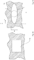
- Figure 3a Figure 12 shows a cross section through the channel 14. It can be seen that the channel 14 can have a non-round cross section. In the case shown in Figure 4a, the cross-section is rectangular.
- Figure 3b shows another possible cross-section of the channel 14, which is flat.
- a first extension (a 1 ) in a first direction which can be referred to as the x-direction, is more than 1.5, in the present case more than twice as large as a second extension a 2 perpendicular to the x-direction, this Direction can be referred to as Y direction.
- the first extent a 1 is significantly larger than an inner circle diameter D I of an inner circle I of the cross section.
- the incircle I touches an edge R of the channel 14 but does not intersect it.
- Figure 2a 12 also schematically shows an inner surface 36 of the inner balance cylinder with a chain line.
- the internal compensating cylinder is the imaginary cylinder that describes the inner surface of the support body 22 with the minimum sum of squares of the deviations.
- a projection of the salt molding 18 onto the inner surface 36 is also drawn with a chain line.
- the area of the projection of the salt molding onto the inner surface is at least one tenth, in particular at least one eighth, preferably at least one sixth, particularly preferably at least one quarter, of the inner surface. A good cooling effect is achieved in this way.
Landscapes
- Engineering & Computer Science (AREA)
- Mechanical Engineering (AREA)
- Power Engineering (AREA)
- Manufacturing & Machinery (AREA)
- Motor Or Generator Frames (AREA)
Priority Applications (7)
| Application Number | Priority Date | Filing Date | Title |
|---|---|---|---|
| PCT/EP2022/053397 WO2022175183A1 (fr) | 2021-02-19 | 2022-02-11 | Procédé et système de production de pièce coulée pour la production d'un carter de moteur électrique, et moteur électrique |
| US18/546,833 US20240307952A1 (en) | 2021-02-19 | 2022-02-11 | Method and cast part production system for producing an electric motor housing, and electric motor |
| CN202280015931.1A CN116867584A (zh) | 2021-02-19 | 2022-02-11 | 用于制造电机壳体的方法及铸件制造设备和电机 |
| KR1020237031377A KR20230147660A (ko) | 2021-02-19 | 2022-02-11 | 전기 모터 하우징을 생산하기 위한 방법 및 주조 부품 생산 시스템, 및 전기 모터 |
| JP2023550144A JP2024506975A (ja) | 2021-02-19 | 2022-02-11 | 電気モータハウジング及び電気モータの製造方法 |
| CA3209004A CA3209004A1 (fr) | 2021-02-19 | 2022-02-11 | Procede et systeme de production de piece coulee pour la production d'un carter de moteur electrique, et moteur electrique |
| EP22702747.1A EP4294589A1 (fr) | 2021-02-19 | 2022-02-11 | Procédé et système de production de pièce coulée pour la production d'un carter de moteur électrique, et moteur électrique |
Applications Claiming Priority (1)
| Application Number | Priority Date | Filing Date | Title |
|---|---|---|---|
| DE102021104024.8A DE102021104024A1 (de) | 2021-02-19 | 2021-02-19 | Verfahren zum Herstellen eines Gussteils und Elektromotor |
Publications (3)
| Publication Number | Publication Date |
|---|---|
| EP4046727A1 true EP4046727A1 (fr) | 2022-08-24 |
| EP4046727C0 EP4046727C0 (fr) | 2024-01-10 |
| EP4046727B1 EP4046727B1 (fr) | 2024-01-10 |
Family
ID=78516603
Family Applications (1)
| Application Number | Title | Priority Date | Filing Date |
|---|---|---|---|
| EP21206171.7A Active EP4046727B1 (fr) | 2021-02-19 | 2021-11-03 | Procédé de fabrication d'une pièce coulée et moteur électrique |
Country Status (5)
| Country | Link |
|---|---|
| EP (1) | EP4046727B1 (fr) |
| DE (1) | DE102021104024A1 (fr) |
| ES (1) | ES2975738T3 (fr) |
| HU (1) | HUE066363T2 (fr) |
| PL (1) | PL4046727T3 (fr) |
Cited By (1)
| Publication number | Priority date | Publication date | Assignee | Title |
|---|---|---|---|---|
| CN120347191A (zh) * | 2025-06-26 | 2025-07-22 | 宁波全力机械模具有限公司 | 一种具有冷却水管的电机壳铸造设备及其铸造方法 |
Citations (14)
| Publication number | Priority date | Publication date | Assignee | Title |
|---|---|---|---|---|
| EP1293276A2 (fr) | 2001-09-18 | 2003-03-19 | DaimlerChrysler AG | Appareil pour fabriquer de pièces coulées sous pression avec un noyau et un insert |
| DE102010054496A1 (de) * | 2010-12-14 | 2012-06-14 | Volkswagen Ag | Verfahren zur Herstellung eines Elektromotorgehäuseteilrohlings und Elektromotorgehäuseteil |
| DE102012022331A1 (de) | 2012-11-14 | 2013-05-16 | Daimler Ag | Salzkern und Herstellverfahren dafür |
| EP2647451A1 (fr) | 2012-04-04 | 2013-10-09 | Bühler AG | Procédé de fabrication de noyaux de sel |
| DE102013101942B3 (de) * | 2013-02-27 | 2014-07-31 | Ks Aluminium-Technologie Gmbh | Kühlmittelmantelkern sowie Verfahren zur Herstellung eines Kühlmittelmantelkerns |
| DE102013015395A1 (de) * | 2013-09-17 | 2015-03-19 | Daimler Ag | Gussbauteil mit wenigstens einem durch einen Gießkern gebildeten porösen Metallkörper |
| DE102014007889A1 (de) | 2013-10-08 | 2015-04-09 | Fraunhofer-Gesellschaft zur Förderung der angewandten Forschung e.V. | Verfahren zur Herstellung eines Salzkörpers, insbesondere für den Druckguss |
| KR101761677B1 (ko) | 2016-12-29 | 2017-08-07 | 엠에이치기술개발 주식회사 | 모터하우징용 냉각장치 |
| EP3208013A1 (fr) | 2016-02-22 | 2017-08-23 | Fraunhofer-Gesellschaft zur Förderung der angewandten Forschung e.V. | Procédé de moulage d'un élément structurel ayant une géométrie complexe à l'aide d'un moule segmenté |
| KR20190026164A (ko) | 2017-09-04 | 2019-03-13 | 엠에이치기술개발 주식회사 | 모터 하우징 냉각장치 및 그 모터 하우징 냉각장치를 구비한 전기 자동차 |
| KR20190026160A (ko) | 2017-09-04 | 2019-03-13 | 엠에이치기술개발 주식회사 | 모터 하우징 냉각장치 및 그 모터 하우징 냉각장치를 구비한 전기 자동차 |
| KR101961155B1 (ko) | 2017-10-17 | 2019-03-22 | 엠에이치기술개발 주식회사 | 비누출 유체 채널이 매립된 모터 하우징 및 이의 제조 방법 |
| KR102055746B1 (ko) | 2018-09-07 | 2019-12-13 | 엠에이치기술개발 주식회사 | 비누출 유체 채널이 매립된 모터 하우징 |
| DE102019112918B3 (de) * | 2019-05-16 | 2020-07-23 | Dr. Ing. H.C. F. Porsche Aktiengesellschaft | Kern zur Verwendung bei einer gießtechnischen Herstellung eines Kurbelgehäuses |
-
2021
- 2021-02-19 DE DE102021104024.8A patent/DE102021104024A1/de active Pending
- 2021-11-03 ES ES21206171T patent/ES2975738T3/es active Active
- 2021-11-03 EP EP21206171.7A patent/EP4046727B1/fr active Active
- 2021-11-03 PL PL21206171.7T patent/PL4046727T3/pl unknown
- 2021-11-03 HU HUE21206171A patent/HUE066363T2/hu unknown
Patent Citations (14)
| Publication number | Priority date | Publication date | Assignee | Title |
|---|---|---|---|---|
| EP1293276A2 (fr) | 2001-09-18 | 2003-03-19 | DaimlerChrysler AG | Appareil pour fabriquer de pièces coulées sous pression avec un noyau et un insert |
| DE102010054496A1 (de) * | 2010-12-14 | 2012-06-14 | Volkswagen Ag | Verfahren zur Herstellung eines Elektromotorgehäuseteilrohlings und Elektromotorgehäuseteil |
| EP2647451A1 (fr) | 2012-04-04 | 2013-10-09 | Bühler AG | Procédé de fabrication de noyaux de sel |
| DE102012022331A1 (de) | 2012-11-14 | 2013-05-16 | Daimler Ag | Salzkern und Herstellverfahren dafür |
| DE102013101942B3 (de) * | 2013-02-27 | 2014-07-31 | Ks Aluminium-Technologie Gmbh | Kühlmittelmantelkern sowie Verfahren zur Herstellung eines Kühlmittelmantelkerns |
| DE102013015395A1 (de) * | 2013-09-17 | 2015-03-19 | Daimler Ag | Gussbauteil mit wenigstens einem durch einen Gießkern gebildeten porösen Metallkörper |
| DE102014007889A1 (de) | 2013-10-08 | 2015-04-09 | Fraunhofer-Gesellschaft zur Förderung der angewandten Forschung e.V. | Verfahren zur Herstellung eines Salzkörpers, insbesondere für den Druckguss |
| EP3208013A1 (fr) | 2016-02-22 | 2017-08-23 | Fraunhofer-Gesellschaft zur Förderung der angewandten Forschung e.V. | Procédé de moulage d'un élément structurel ayant une géométrie complexe à l'aide d'un moule segmenté |
| KR101761677B1 (ko) | 2016-12-29 | 2017-08-07 | 엠에이치기술개발 주식회사 | 모터하우징용 냉각장치 |
| KR20190026164A (ko) | 2017-09-04 | 2019-03-13 | 엠에이치기술개발 주식회사 | 모터 하우징 냉각장치 및 그 모터 하우징 냉각장치를 구비한 전기 자동차 |
| KR20190026160A (ko) | 2017-09-04 | 2019-03-13 | 엠에이치기술개발 주식회사 | 모터 하우징 냉각장치 및 그 모터 하우징 냉각장치를 구비한 전기 자동차 |
| KR101961155B1 (ko) | 2017-10-17 | 2019-03-22 | 엠에이치기술개발 주식회사 | 비누출 유체 채널이 매립된 모터 하우징 및 이의 제조 방법 |
| KR102055746B1 (ko) | 2018-09-07 | 2019-12-13 | 엠에이치기술개발 주식회사 | 비누출 유체 채널이 매립된 모터 하우징 |
| DE102019112918B3 (de) * | 2019-05-16 | 2020-07-23 | Dr. Ing. H.C. F. Porsche Aktiengesellschaft | Kern zur Verwendung bei einer gießtechnischen Herstellung eines Kurbelgehäuses |
Cited By (1)
| Publication number | Priority date | Publication date | Assignee | Title |
|---|---|---|---|---|
| CN120347191A (zh) * | 2025-06-26 | 2025-07-22 | 宁波全力机械模具有限公司 | 一种具有冷却水管的电机壳铸造设备及其铸造方法 |
Also Published As
| Publication number | Publication date |
|---|---|
| PL4046727T3 (pl) | 2024-06-17 |
| HUE066363T2 (hu) | 2024-08-28 |
| ES2975738T3 (es) | 2024-07-12 |
| DE102021104024A1 (de) | 2022-08-25 |
| EP4046727C0 (fr) | 2024-01-10 |
| EP4046727B1 (fr) | 2024-01-10 |
Similar Documents
| Publication | Publication Date | Title |
|---|---|---|
| DE19650613B4 (de) | Bauteil mit einem Metallschaum-Kern | |
| EP2625430B1 (fr) | Méthode de fabrication d'un carter de turbochargeur | |
| WO2008138508A1 (fr) | Procédé pour réaliser un carter moteur | |
| EP0872295B1 (fr) | Moule de coulage et procédé de fabrication de pièces coulées creuses et pièces coulées creuses | |
| DE102011076312A1 (de) | Kühlvorrichtung für ein Gehäuse | |
| EP1929146B8 (fr) | Procede pour fabriquer un piston de moteur thermique et piston ainsi realise | |
| DE102016123491B4 (de) | Gießvorrichtung, Presse und Verfahren zum Gießen eines Bauteils | |
| DE102017203435A1 (de) | Kühlmantelbauteil für ein Gehäuse einer elektrischen Maschine | |
| DE102019130768A1 (de) | Kühlvorrichtung mit ultradünnem kühlpfad und herstellungsverfahren davon | |
| EP4046727B1 (fr) | Procédé de fabrication d'une pièce coulée et moteur électrique | |
| DE69417494T2 (de) | Gussform | |
| EP4294589A1 (fr) | Procédé et système de production de pièce coulée pour la production d'un carter de moteur électrique, et moteur électrique | |
| WO2015039730A1 (fr) | Pièce coulée dotée d'au moins un corps métallique poreux formé par l'intermédiaire d'un noyau de coulée | |
| EP3771506B1 (fr) | Procédé de coulée au moyen d'un contour de moulage destiné à la fabrication d'un noyau, composant et système de fabrication d'un composant | |
| EP2738377A2 (fr) | Procédé de fabrication d'un bloc moteur | |
| WO2016155911A1 (fr) | Chemise de carter refroidie par un fluide pour une moteur électrique et procédé de fabrication d'une chemise de carter | |
| EP1204516B1 (fr) | Procede de realisation d'un corps creux par la technique de moulage a noyau fusible | |
| EP3737515B1 (fr) | Dispositif de coulage ainsi que son procede d'utilisation | |
| DE102020211765A1 (de) | Vorrichtung und Verfahren zum vertikalen Druckgießen eines Rotors für einen Asynchronmotor | |
| AT503391A1 (de) | Verfahren zum feingiessen von metallischen formteilen und vorrichtung hierfür | |
| DE102024001656B3 (de) | Formkörper für eine Gussform und Verfahren zur Herstellung des Formkörpers | |
| DE102024117299B3 (de) | Gussform und Verfahren zum Vermindern von Lufteinschlüssen in einem Gussartikel | |
| EP4286074A1 (fr) | Procédé de fabrication d'une pièce coulée et moteur électrique | |
| WO2020048717A1 (fr) | Procédé pour la coulée sous pression de métal à noyau perdu | |
| EP1087856B1 (fr) | Procede pour produire des composants renforces par des fibres longues et fibres |
Legal Events
| Date | Code | Title | Description |
|---|---|---|---|
| PUAI | Public reference made under article 153(3) epc to a published international application that has entered the european phase |
Free format text: ORIGINAL CODE: 0009012 |
|
| STAA | Information on the status of an ep patent application or granted ep patent |
Free format text: STATUS: THE APPLICATION HAS BEEN PUBLISHED |
|
| AK | Designated contracting states |
Kind code of ref document: A1 Designated state(s): AL AT BE BG CH CY CZ DE DK EE ES FI FR GB GR HR HU IE IS IT LI LT LU LV MC MK MT NL NO PL PT RO RS SE SI SK SM TR |
|
| STAA | Information on the status of an ep patent application or granted ep patent |
Free format text: STATUS: REQUEST FOR EXAMINATION WAS MADE |
|
| TPAC | Observations filed by third parties |
Free format text: ORIGINAL CODE: EPIDOSNTIPA |
|
| 17P | Request for examination filed |
Effective date: 20220922 |
|
| RBV | Designated contracting states (corrected) |
Designated state(s): AL AT BE BG CH CY CZ DE DK EE ES FI FR GB GR HR HU IE IS IT LI LT LU LV MC MK MT NL NO PL PT RO RS SE SI SK SM TR |
|
| STAA | Information on the status of an ep patent application or granted ep patent |
Free format text: STATUS: EXAMINATION IS IN PROGRESS |
|
| 17Q | First examination report despatched |
Effective date: 20230206 |
|
| GRAP | Despatch of communication of intention to grant a patent |
Free format text: ORIGINAL CODE: EPIDOSNIGR1 |
|
| STAA | Information on the status of an ep patent application or granted ep patent |
Free format text: STATUS: GRANT OF PATENT IS INTENDED |
|
| RIC1 | Information provided on ipc code assigned before grant |
Ipc: H02K 15/14 20060101ALI20230626BHEP Ipc: H02K 5/20 20060101ALI20230626BHEP Ipc: B22D 15/02 20060101ALI20230626BHEP Ipc: B22C 9/10 20060101AFI20230626BHEP |
|
| INTG | Intention to grant announced |
Effective date: 20230801 |
|
| GRAS | Grant fee paid |
Free format text: ORIGINAL CODE: EPIDOSNIGR3 |
|
| GRAA | (expected) grant |
Free format text: ORIGINAL CODE: 0009210 |
|
| STAA | Information on the status of an ep patent application or granted ep patent |
Free format text: STATUS: THE PATENT HAS BEEN GRANTED |
|
| AK | Designated contracting states |
Kind code of ref document: B1 Designated state(s): AL AT BE BG CH CY CZ DE DK EE ES FI FR GB GR HR HU IE IS IT LI LT LU LV MC MK MT NL NO PL PT RO RS SE SI SK SM TR |
|
| REG | Reference to a national code |
Ref country code: GB Ref legal event code: FG4D Free format text: NOT ENGLISH |
|
| REG | Reference to a national code |
Ref country code: CH Ref legal event code: EP |
|
| REG | Reference to a national code |
Ref country code: DE Ref legal event code: R096 Ref document number: 502021002417 Country of ref document: DE |
|
| REG | Reference to a national code |
Ref country code: IE Ref legal event code: FG4D Free format text: LANGUAGE OF EP DOCUMENT: GERMAN |
|
| U01 | Request for unitary effect filed |
Effective date: 20240126 |
|
| U07 | Unitary effect registered |
Designated state(s): AT BE BG DE DK EE FI FR IT LT LU LV MT NL PT SE SI Effective date: 20240206 |
|
| REG | Reference to a national code |
Ref country code: SK Ref legal event code: T3 Ref document number: E 43877 Country of ref document: SK |
|
| PG25 | Lapsed in a contracting state [announced via postgrant information from national office to epo] |
Ref country code: IS Free format text: LAPSE BECAUSE OF FAILURE TO SUBMIT A TRANSLATION OF THE DESCRIPTION OR TO PAY THE FEE WITHIN THE PRESCRIBED TIME-LIMIT Effective date: 20240510 |
|
| REG | Reference to a national code |
Ref country code: ES Ref legal event code: FG2A Ref document number: 2975738 Country of ref document: ES Kind code of ref document: T3 Effective date: 20240712 |
|
| PG25 | Lapsed in a contracting state [announced via postgrant information from national office to epo] |
Ref country code: HR Free format text: LAPSE BECAUSE OF FAILURE TO SUBMIT A TRANSLATION OF THE DESCRIPTION OR TO PAY THE FEE WITHIN THE PRESCRIBED TIME-LIMIT Effective date: 20240110 Ref country code: RS Free format text: LAPSE BECAUSE OF FAILURE TO SUBMIT A TRANSLATION OF THE DESCRIPTION OR TO PAY THE FEE WITHIN THE PRESCRIBED TIME-LIMIT Effective date: 20240410 |
|
| PG25 | Lapsed in a contracting state [announced via postgrant information from national office to epo] |
Ref country code: RS Free format text: LAPSE BECAUSE OF FAILURE TO SUBMIT A TRANSLATION OF THE DESCRIPTION OR TO PAY THE FEE WITHIN THE PRESCRIBED TIME-LIMIT Effective date: 20240410 Ref country code: IS Free format text: LAPSE BECAUSE OF FAILURE TO SUBMIT A TRANSLATION OF THE DESCRIPTION OR TO PAY THE FEE WITHIN THE PRESCRIBED TIME-LIMIT Effective date: 20240510 Ref country code: HR Free format text: LAPSE BECAUSE OF FAILURE TO SUBMIT A TRANSLATION OF THE DESCRIPTION OR TO PAY THE FEE WITHIN THE PRESCRIBED TIME-LIMIT Effective date: 20240110 |
|
| REG | Reference to a national code |
Ref country code: HU Ref legal event code: AG4A Ref document number: E066363 Country of ref document: HU |
|
| REG | Reference to a national code |
Ref country code: DE Ref legal event code: R097 Ref document number: 502021002417 Country of ref document: DE |
|
| PG25 | Lapsed in a contracting state [announced via postgrant information from national office to epo] |
Ref country code: SM Free format text: LAPSE BECAUSE OF FAILURE TO SUBMIT A TRANSLATION OF THE DESCRIPTION OR TO PAY THE FEE WITHIN THE PRESCRIBED TIME-LIMIT Effective date: 20240110 |
|
| PG25 | Lapsed in a contracting state [announced via postgrant information from national office to epo] |
Ref country code: SM Free format text: LAPSE BECAUSE OF FAILURE TO SUBMIT A TRANSLATION OF THE DESCRIPTION OR TO PAY THE FEE WITHIN THE PRESCRIBED TIME-LIMIT Effective date: 20240110 |
|
| PLBE | No opposition filed within time limit |
Free format text: ORIGINAL CODE: 0009261 |
|
| STAA | Information on the status of an ep patent application or granted ep patent |
Free format text: STATUS: NO OPPOSITION FILED WITHIN TIME LIMIT |
|
| 26N | No opposition filed |
Effective date: 20241011 |
|
| U20 | Renewal fee for the european patent with unitary effect paid |
Year of fee payment: 4 Effective date: 20241127 |
|
| PG25 | Lapsed in a contracting state [announced via postgrant information from national office to epo] |
Ref country code: MC Free format text: LAPSE BECAUSE OF FAILURE TO SUBMIT A TRANSLATION OF THE DESCRIPTION OR TO PAY THE FEE WITHIN THE PRESCRIBED TIME-LIMIT Effective date: 20240110 |
|
| REG | Reference to a national code |
Ref country code: CH Ref legal event code: U11 Free format text: ST27 STATUS EVENT CODE: U-0-0-U10-U11 (AS PROVIDED BY THE NATIONAL OFFICE) Effective date: 20251201 |
|
| PGFP | Annual fee paid to national office [announced via postgrant information from national office to epo] |
Ref country code: HU Payment date: 20251031 Year of fee payment: 5 |
|
| U20 | Renewal fee for the european patent with unitary effect paid |
Year of fee payment: 5 Effective date: 20251120 |
|
| PGFP | Annual fee paid to national office [announced via postgrant information from national office to epo] |
Ref country code: GB Payment date: 20251120 Year of fee payment: 5 |
|
| PGFP | Annual fee paid to national office [announced via postgrant information from national office to epo] |
Ref country code: NO Payment date: 20251118 Year of fee payment: 5 |
|
| PGFP | Annual fee paid to national office [announced via postgrant information from national office to epo] |
Ref country code: TR Payment date: 20251030 Year of fee payment: 5 |
|
| PGFP | Annual fee paid to national office [announced via postgrant information from national office to epo] |
Ref country code: CH Payment date: 20251201 Year of fee payment: 5 |
|
| PGFP | Annual fee paid to national office [announced via postgrant information from national office to epo] |
Ref country code: IE Payment date: 20251120 Year of fee payment: 5 Ref country code: CZ Payment date: 20251021 Year of fee payment: 5 |
|
| PGFP | Annual fee paid to national office [announced via postgrant information from national office to epo] |
Ref country code: PL Payment date: 20251021 Year of fee payment: 5 |
|
| PGFP | Annual fee paid to national office [announced via postgrant information from national office to epo] |
Ref country code: RO Payment date: 20251028 Year of fee payment: 5 Ref country code: SK Payment date: 20251022 Year of fee payment: 5 |
|
| PGFP | Annual fee paid to national office [announced via postgrant information from national office to epo] |
Ref country code: ES Payment date: 20251216 Year of fee payment: 5 |
|
| PG25 | Lapsed in a contracting state [announced via postgrant information from national office to epo] |
Ref country code: CY Free format text: LAPSE BECAUSE OF FAILURE TO SUBMIT A TRANSLATION OF THE DESCRIPTION OR TO PAY THE FEE WITHIN THE PRESCRIBED TIME-LIMIT; INVALID AB INITIO Effective date: 20211103 |