EP3208095B1 - Imprimante numérique - Google Patents
Imprimante numérique Download PDFInfo
- Publication number
- EP3208095B1 EP3208095B1 EP15850370.6A EP15850370A EP3208095B1 EP 3208095 B1 EP3208095 B1 EP 3208095B1 EP 15850370 A EP15850370 A EP 15850370A EP 3208095 B1 EP3208095 B1 EP 3208095B1
- Authority
- EP
- European Patent Office
- Prior art keywords
- printing cylinder
- abnormality
- sheet
- printing
- cylinder
- Prior art date
- Legal status (The legal status is an assumption and is not a legal conclusion. Google has not performed a legal analysis and makes no representation as to the accuracy of the status listed.)
- Not-in-force
Links
Images


Classifications
-
- B—PERFORMING OPERATIONS; TRANSPORTING
- B41—PRINTING; LINING MACHINES; TYPEWRITERS; STAMPS
- B41J—TYPEWRITERS; SELECTIVE PRINTING MECHANISMS, i.e. MECHANISMS PRINTING OTHERWISE THAN FROM A FORME; CORRECTION OF TYPOGRAPHICAL ERRORS
- B41J29/00—Details of, or accessories for, typewriters or selective printing mechanisms not otherwise provided for
- B41J29/38—Drives, motors, controls or automatic cut-off devices for the entire printing mechanism
-
- B—PERFORMING OPERATIONS; TRANSPORTING
- B41—PRINTING; LINING MACHINES; TYPEWRITERS; STAMPS
- B41J—TYPEWRITERS; SELECTIVE PRINTING MECHANISMS, i.e. MECHANISMS PRINTING OTHERWISE THAN FROM A FORME; CORRECTION OF TYPOGRAPHICAL ERRORS
- B41J11/00—Devices or arrangements of selective printing mechanisms, e.g. ink-jet printers or thermal printers, for supporting or handling copy material in sheet or web form
- B41J11/36—Blanking or long feeds; Feeding to a particular line, e.g. by rotation of platen or feed roller
- B41J11/42—Controlling printing material conveyance for accurate alignment of the printing material with the printhead; Print registering
-
- B—PERFORMING OPERATIONS; TRANSPORTING
- B41—PRINTING; LINING MACHINES; TYPEWRITERS; STAMPS
- B41J—TYPEWRITERS; SELECTIVE PRINTING MECHANISMS, i.e. MECHANISMS PRINTING OTHERWISE THAN FROM A FORME; CORRECTION OF TYPOGRAPHICAL ERRORS
- B41J13/00—Devices or arrangements of selective printing mechanisms, e.g. ink-jet printers or thermal printers, specially adapted for supporting or handling copy material in short lengths, e.g. sheets
- B41J13/0009—Devices or arrangements of selective printing mechanisms, e.g. ink-jet printers or thermal printers, specially adapted for supporting or handling copy material in short lengths, e.g. sheets control of the transport of the copy material
- B41J13/0027—Devices or arrangements of selective printing mechanisms, e.g. ink-jet printers or thermal printers, specially adapted for supporting or handling copy material in short lengths, e.g. sheets control of the transport of the copy material in the printing section of automatic paper handling systems
-
- B—PERFORMING OPERATIONS; TRANSPORTING
- B41—PRINTING; LINING MACHINES; TYPEWRITERS; STAMPS
- B41J—TYPEWRITERS; SELECTIVE PRINTING MECHANISMS, i.e. MECHANISMS PRINTING OTHERWISE THAN FROM A FORME; CORRECTION OF TYPOGRAPHICAL ERRORS
- B41J2/00—Typewriters or selective printing mechanisms characterised by the printing or marking process for which they are designed
- B41J2/005—Typewriters or selective printing mechanisms characterised by the printing or marking process for which they are designed characterised by bringing liquid or particles selectively into contact with a printing material
- B41J2/01—Ink jet
-
- B—PERFORMING OPERATIONS; TRANSPORTING
- B65—CONVEYING; PACKING; STORING; HANDLING THIN OR FILAMENTARY MATERIAL
- B65H—HANDLING THIN OR FILAMENTARY MATERIAL, e.g. SHEETS, WEBS, CABLES
- B65H7/00—Controlling article feeding, separating, pile-advancing, or associated apparatus, to take account of incorrect feeding, absence of articles, or presence of faulty articles
- B65H7/02—Controlling article feeding, separating, pile-advancing, or associated apparatus, to take account of incorrect feeding, absence of articles, or presence of faulty articles by feelers or detectors
- B65H7/06—Controlling article feeding, separating, pile-advancing, or associated apparatus, to take account of incorrect feeding, absence of articles, or presence of faulty articles by feelers or detectors responsive to presence of faulty articles or incorrect separation or feed
-
- B—PERFORMING OPERATIONS; TRANSPORTING
- B41—PRINTING; LINING MACHINES; TYPEWRITERS; STAMPS
- B41J—TYPEWRITERS; SELECTIVE PRINTING MECHANISMS, i.e. MECHANISMS PRINTING OTHERWISE THAN FROM A FORME; CORRECTION OF TYPOGRAPHICAL ERRORS
- B41J13/00—Devices or arrangements of selective printing mechanisms, e.g. ink-jet printers or thermal printers, specially adapted for supporting or handling copy material in short lengths, e.g. sheets
- B41J13/10—Sheet holders, retainers, movable guides, or stationary guides
- B41J13/22—Clamps or grippers
- B41J13/223—Clamps or grippers on rotatable drums
Definitions
- the present invention relates to a digital printing press that performs digital printing on a sheet.
- patent literature 1 As a conventional digital printing press, there exists an inkjet type described in, for example, patent literature 1.
- a sheet rotates together with a printing cylinder and is thus transported between an inkjet nozzle head (to be simply referred to as an inkjet head hereinafter) and the printing cylinder.
- Printing is performed by ejecting ink from the inkjet head to the sheet in a state in which the sheet is located between the printing cylinder and the inkjet head.
- the inkjet head is arranged at a position where a small gap is formed with respect to the sheet. For this reason, if the sheet partially floats up from the printing cylinder, the distance between the sheet and the inkjet head changes to cause a print error. Additionally, the floating portion may contact the inkjet head, and the inkjet head may be damaged.
- the conventional digital printing press includes a floating detector configured to detect a portion of a sheet floating from the printing cylinder.
- the conventional digital printing press including an abnormality detector like the floating detector employs an arrangement that stops a motor for driving the printing cylinder and stops the printing cylinder upon detecting an abnormality during printing.
- the printing cylinder slightly rotates by inertia during the time after an abnormality is detected during printing, and the drive motor stops until the printing cylinder comes to rest. For this reason, the abnormality occurrence portion can hardly be specified, and the time needed to cope with the abnormality or track down the cause of the abnormality becomes long.
- the present invention has been made to solve the above-described problem, and has as its object to provide a digital printing press capable of quickly specifying an abnormality occurrence portion detected during printing.
- the printing cylinder stops, and the abnormality occurrence portion moves to a predetermined confirmation position which is a position facing the abnormality detector.
- the abnormality occurrence portion can be searched for in a state in which the position of the abnormality occurrence portion is approximately estimated. It is therefore possible to easily find the abnormality occurrence portion.
- a sheet 4 is transported from a feeder unit 2 located at the rightmost position in Fig. 1 to a print unit 3, and the print unit 3 prints one surface or both surfaces of the sheet 4.
- the sheet 4 printed by the print unit 3 is fed to a delivery unit 5 and discharged to a delivery pile 6.
- the feeder unit 2 involves a mechanism to transfer the sheet 4 from a feeder pile 11 to a feeder board 13 by a sucker 12.
- the sucker 12 is connected to an intermittent feeder valve 14, and operates in one of a mode to continuously feed the sheet 4 and a mode to intermittently feed the sheet 4.
- the sucker 12 continuously feeds the sheet 4 to the feeder board 13.
- the sucker 12 intermittently feeds the sheet 4 to the feeder board 13.
- the print unit 3 includes a feeder-side transfer cylinder 16 to which the sheet 4 supplied from the feeder unit 2 is transported by a feeder-side swing device 15, a printing cylinder 17 to which the sheet 4 is fed from the feeder-side transfer cylinder 16, and a plurality of transport cylinders 18 to 21 to which the sheet 4 after printing is fed.
- the printing cylinder 17 involves a mechanism to suck and hold the sheet 4.
- the print unit 3 also includes a floating detector 22 located on the downstream side of the feeder-side transfer cylinder 16 in the transportation direction, first to fourth inkjet nozzle heads 23 to 26 located on the downstream side of the floating detector 22 in the transportation direction, and an ink drying lamp 27 located on the downstream side of the fourth inkjet nozzle head 26 in the transportation direction.
- the floating detector 22 detects a portion of the sheet 4 sucked and transported by the printing cylinder 17, the portion which is separated from the surface of the printing cylinder 17.
- the portion of the sheet 4 separated from the surface of the printing cylinder 17 will simply be referred to as a "floating portion” hereinafter.
- the floating detector 22 can be formed from a noncontact detector including a photoelectric sensor, a contact detector including a contactor (not shown) that comes into contact with the sheet 4, or the like.
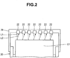
- the floating detector 22 detects a floating portion of the sheet 4 and sends the detection result as detection data to a control device 28 (see Fig. 3 ) to be described later. If the floating detector 22 is formed from a noncontact detector, a plurality of floating detectors 22 are arranged at positions facing the outer surface of the printing cylinder 17, as shown in Fig. 2 . The floating detectors 22 each irradiate the printing cylinder 17 (sheet 4) with irradiation light L1, and detect light L2 reflected by the sheet 4, thereby measuring the interval between the surface of the sheet 4 and the floating detector 22.
- the floating detectors 22 are arranged at a predetermined interval in the axial direction (the horizontal direction in Fig. 2 ) of the printing cylinder 17 and, in this state, supported by a frame 30 via a bracket 29.
- the frame 30 rotatably supports the printing cylinder 17 and the transport cylinders 18 to 21.
- the floating detector 22 corresponds to "abnormality detector" of the present invention.
- the abnormality detector of the present invention can be formed by a temperature detector 31 (see Fig. 1 ).
- the sheet 4 is heated to improve print quality.
- the temperature detector 31 is provide at a position facing the printing cylinder 17 to measure the surface temperature of the sheet 4 or the surface temperature of the printing cylinder 17.
- the first to fourth inkjet nozzle heads 23 to 26 each eject ink and make it adhere to the sheet 4.
- the first to fourth inkjet nozzle heads 23 to 26 are supported by a head moving device 32.
- the head moving device 32 moves the first to fourth inkjet nozzle heads 23 to 26 between a print position close to the printing cylinder 17 and a separate position separated from the printing cylinder 17.
- the head moving device 32 for example, the same device as described in Japanese Patent Laid-Open No. 2013-248879 can be used.
- the first to fourth inkjet nozzle heads 23 to 26 located at the print position are indicated by solid lines.
- the first to fourth inkjet nozzle heads 23 to 26 move to positions indicated by alternate long and two short dashed lines.
- the operation of the head moving device 32 is controlled by the control device 28 (to be described later).
- the ink drying lamp 27 cures the ink applied to the sheet 4 by the first to fourth inkjet nozzle heads 23 to 26.
- the plurality of transport cylinders described above include the first discharge-side transfer cylinder 18 that receives the sheet 4 from the printing cylinder 17, the second discharge-side transfer cylinder 19 that receives the sheet 4 from the first discharge-side transfer cylinder 18, and the delivery cylinder 20 and the pre-reversal double-size cylinder 21 both of which receive the sheet 4 from the second discharge-side transfer cylinder 19.
- the sheet 4 whose reverse surface should be printed is transported from the second discharge-side transfer cylinder 19 to the pre-reversal double-size cylinder 21.
- the sheet 4 whose obverse surface should only be printed or the sheet 4 with the obverse and reverse surfaces printed is fed from the second discharge-side transfer cylinder 19 to the delivery cylinder 20 and fed to the delivery pile 6 via a delivery belt 33.
- the feeder-side transfer cylinder 16, the printing cylinder 17, the first discharge-side transfer cylinder 18, the second discharge-side transfer cylinder 19, the delivery cylinder 20, and the pre-reversal double-size cylinder 21 include gripper devices 34 to 39, respectively, to transfer the sheet 4.
- the gripper devices 34 to 39 each have a conventionally known structure to grip and hold the leading edge of the sheet 4 in the feeding direction.
- the gripper device 35 of the printing cylinder 17 is provided at each of positions dividing the outer surface of the printing cylinder 17 into three equal parts.
- a reversing swing device 40 configured to feed the sheet 4 from the pre-reversal double-size cylinder 21 to the printing cylinder 17 is arranged between the pre-reversal double-size cylinder 21 and the feeder-side transfer cylinder 16.
- the reversing swing device 40 grips the trailing edge of the sheet 4 in the feeding direction, the portion which is fed by the pre-reversal double-size cylinder 21, and feeds the sheet 4 to the printing cylinder 17 in a state in which the obverse surface faces the printing cylinder 17.
- the plurality of cylinders 16 to 21 and the two swing devices 15 and 40 included in the print unit 3 are driven by a driving device 41 (see Fig. 3 ).
- the driving device 41 includes a printing cylinder drive motor 42 configured to drive the plurality of transport cylinders 16 to 21, including the printing cylinder 17, and a pre-reversal double-size cylinder drive motor 43 configured to drive only the pre-reversal double-size cylinder 21.
- the operation of the driving device 41 is controlled by the control device 28.
- the driving device 41 also includes an encoder 44 that detects the angle of rotation of the printing cylinder drive motor 42.
- the encoder 44 sends the angle of rotation of the printing cylinder drive motor 42 as detection data to the control device 28.
- the encoder 44 corresponds to "phase detector" of the present invention.
- the control device 28 is configured to control the operation of the digital printing press 1, and includes a motor driving unit 51, a nozzle head driving unit 52, an angle detection unit 53, an abnormality detection unit 54, and a storage unit 55.
- An abnormal portion confirmation switch 56 to be artificially operated is connected to the control device 28.
- the motor driving unit 51 When the digital printing press 1 performs printing, the motor driving unit 51 operates the driving device 41 to obtain a predetermined print speed. If the abnormality detection unit 54 (to be described later) detects an abnormality, the motor driving unit 51 operates the driving device 41 in accordance with a predetermined control procedure at the time of abnormality detection.
- the nozzle head driving unit 52 When the digital printing press 1 performs printing, the nozzle head driving unit 52 operates the first to fourth inkjet nozzle heads 23 to 26 and also operates the ink drying lamp 27. If the abnormality detection unit 54 (to be described later) detects an abnormality, the nozzle head driving unit 52 operates the head moving device 32 to move the first to fourth inkjet nozzle heads 23 to 26 to the separate position.
- the angle detection unit 53 detects the angle of rotation of the printing cylinder 17 based on output data of the encoder 44. That is, the output data of the encoder 44 is data specifiable the phase of the printing cylinder 17.
- the abnormality detection unit 54 detects, as an abnormality, a case in which the height (floating amount) of a floating portion of the sheet 4 detected by the floating detector 22 is more than a predetermined determination value.
- the abnormality detection unit 54 according to this embodiment stores the angle of rotation of the printing cylinder 17 upon detecting an abnormality in the storage unit 55.
- the angle of rotation of the printing cylinder 17 is a value detected by the angle detection unit 53.
- the abnormal portion confirmation switch 56 is configured to execute part of the control procedure at the time of abnormality detection according to this embodiment.
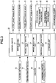
- the control procedure at the time of abnormality detection will be described here with reference to the flowchart of Fig. 4 .
- Control at the time of abnormality detection is started by detecting a floating portion of the sheet 4 by the floating detector 22 in step S1 of the flowchart shown in Fig. 4 .
- a description will be made here assuming a state in which the floating detector 22 detects a floating portion whose height is detected by the abnormality detection unit 54 of the control device 28 as an abnormality.
- step S2 the control device 28 stores the angle of rotation (phase) of the printing cylinder 17 at the time of floating detection. Note that in Fig. 4 , the angle of rotation of the printing cylinder 17 at the time of floating detection is simply described as "floating detection angle”.
- step S3 the control device 28 stops power supply to the printing cylinder drive motor 42 and the pre-reversal double-size cylinder drive motor 43 of the driving device 41 and stops the driving device 41. That is, the control device 28 includes a function of stopping the driving device 41 when the floating detector 22 (abnormality detector) detects a floating portion (abnormality).
- the printing cylinder drive motor 42 of the driving device 41 rotates the printing cylinder 17 and the plurality of transport cylinders 16 to 20 at a high speed during printing. Hence, because an inertial force acts, each of the printing cylinder 17 and the plurality of transport cylinders 16 to 20 rotates by inertia by a predetermined angle after the stop of power supply to the driving device 41, and then stops and comes to rest.
- the control device 28 stops the driving device 41 as described above, and after that, stands by until the abnormal portion confirmation switch 56 is operated, as indicated by step S4. During the standby time, an inspection operation of the printing cylinder 17 by the operator (not shown) can be executed.
- the control device 28 reads out the angle of rotation of the printing cylinder 17 from the storage unit 55 in step S5, and detects the current angle of rotation (phase) of the printing cylinder 17 in step S6. Note that in Fig. 4 , the current angle of rotation of the printing cylinder 17 is simply described as "current angle”.
- step S7 the control device 28 determines whether the current angle of rotation of the printing cylinder 17 matches the angle of rotation at the time of floating detection. If the current angle of rotation does not equal the angle of rotation at the time of floating detection, the process advances to step S8.
- the control device 28 rotates the printing cylinder drive motor 42 by a predetermined angle in a reverse direction. The process then returns to step S6 to detect the current angle of the printing cylinder 17.
- the return operation of rotating the printing cylinder drive motor 42 in the reverse direction is performed until the current angle of rotation of the printing cylinder 17 matches the angle of rotation at the time of floating detection. If the current angle of rotation matches the angle of rotation at the time of floating detection, the control device 28 stops the printing cylinder drive motor 42 (step S9). As described above, by rotating the printing cylinder 17 in the reverse direction, the floating portion of the sheet 4 is located at a position facing the floating detector 22.
- control device 28 includes a function of operating the driving device 41 based on the angle of rotation (phase) of the printing cylinder 17 when the floating detector 22 detects the floating portion and the angle of rotation (phase) of the printing cylinder 17 when the driving device 41 stops after the floating detection and moving the floating portion (abnormality occurrence portion) detected by the floating detector 22 to a position facing the floating detector 22.
- the position facing the floating detector 22 corresponds to "predetermined confirmation position" of the present invention.
- the printing cylinder 17 stops after the floating detector 22 detects the floating portion of the sheet 4.
- the abnormal portion confirmation switch 56 is operated, the floating portion moves to the position facing the floating detector 22. According to this embodiment, since the floating portion can be searched for in a state in which the position of the floating portion is approximately estimated, it is possible to easily find the floating portion.
- a digital printing press capable of quickly specifying a floating portion detected during printing.
- the temperature detector 31 is used in place of the floating detector 22, a digital printing press capable of easily finding an abnormal portion where the temperature of the printing cylinder 17 or sheet 4 is abnormal can be provided.
- the abnormality detector according to this embodiment is formed from the floating detector 22 that detects a portion of the sheet 4 transported by the printing cylinder 17, the portion which is separated from the surface of the printing cylinder 17.
- the digital printing press 1 includes the abnormal portion confirmation switch 56 to be artificially operated.
- the control device 28 starts the operation of locating the floating portion at the position (confirmation position) facing the floating detector 22 when the abnormal portion confirmation switch 56 is operated in a state in which the floating detector 22 detects the floating portion of the sheet 4, and the driving device 41 is at rest.
- the operator can designate the time to rotate the printing cylinder 17 such that the floating portion is located at the position facing the floating detector 22. That is, after the floating of the sheet 4 is detected, and the printing cylinder 17 stops, the printing cylinder 17 can be operated after safety check.
- the digital printing press 1 includes the head moving device 32 that moves the first to fourth inkjet nozzle heads 23 to 26 between the print position close to the printing cylinder 17 and the separate position separated from the printing cylinder 17.
- the head moving device 32 is configured to move the first to fourth inkjet nozzle heads 23 to 26 from the print position to the separate position when the floating detector 22 detects an abnormality.
- the confirmation position according to the invention is the position facing the floating detector 22.
- the confirmation position can be changed as needed as long as it is a position where the portion of the sheet 4 facing the floating detector 22 at the time of floating detection can be easily visually recognized. If the position that can be easily visually recognized is located on the downstream side of the fourth inkjet nozzle head 26 in the transportation direction of the sheet 4, the printing cylinder 17 rotates by a predetermined angle after the abnormal portion confirmation switch 56 is operated.
- 1...digital printing press 4...sheet, 17...printing cylinder, 22...floating detector, 23...first inkjet nozzle head, 24...second inkjet nozzle head, 25...third inkjet nozzle head, 26...fourth inkjet nozzle head, 28...control device, 41...driving device, 44...encoder (phase detector).
Landscapes
- Ink Jet (AREA)
- Accessory Devices And Overall Control Thereof (AREA)
- Common Mechanisms (AREA)
- Handling Of Sheets (AREA)
Claims (5)
- Presse d'impression numérique comprenant:un cylindre d'impression configuré pour maintenir et transporter une feuille découpée;un dispositif d'entraînement incluant un moteur d'entraînement de cylindre d'impression configuré pour entraîner le cylindre d'impression;un détecteur de phase configuré pour sortir des données de détection pouvant spécifier une phase du cylindre d'impression;une tête de buse à jet d'encre située dans une position faisant face au cylindre d'impression et configurée pour imprimer la feuille;un détecteur d'anomalie situé dans une position faisant face au cylindre d'impression et configuré pour détecter une anomalie de l'un parmi le cylindre d'impression et la feuille;un commutateur de confirmation de partie anormale; etun dispositif de commande configuré pour commander une opération du dispositif d'entraînement,dans laquelle le dispositif de commande inclut une unité de stockage,une fonction d'arrêt du dispositif d'entraînement quand le détecteur d'anomalie détecte l'anomalie, etune fonction d'actionnement du dispositif d'entraînement basée sur la phase du cylindre d'impression quand le détecteur d'anomalie détecte l'anomalie et la phase du cylindre d'impression quand le dispositif d'entraînement s'arrête après la détection d'anomalie,dans laquelle, lorsque le commutateur de confirmation de partie anormale est actionné, l'angle de rotation du cylindre d'impression est lu depuis l'unité de stockage et la phase de rotation actuelle du cylindre d'impression est détectée et une partie d'apparition d'anomalie détectée par le détecteur d'anomalie est déplacée vers une position de confirmation prédéterminée en faisant tourner le moteur d'entraînement de cylindre d'impression dans une direction inverse jusqu'à ce que la phase actuelle du cylindre d'impression corresponde à la phase du cylindre d'impression au moment de la détection d'anomalie,la position de confirmation prédéterminée étant une position faisant face au détecteur d'anomalie.
- Presse d'impression numérique selon la revendication 1, dans laquelle le détecteur d'anomalie détecte une partie de la feuille transportée par le cylindre d'impression, la partie qui est séparée d'une surface du cylindre d'impression.
- Presse d'impression numérique selon la revendication 1 ou 2,
dans laquelle le dispositif de commande commence une opération de localisation de la partie d'apparition d'anomalie dans la position de confirmation quand le commutateur de confirmation de partie anormale est actionné dans un état dans lequel le détecteur d'anomalie détecte l'anomalie, et le dispositif d'entraînement est au repos. - Presse d'impression numérique selon l'une quelconque des revendications 1 à 3, comprenant en outre un dispositif de déplacement de tête configuré pour déplacer la tête de buse à jet d'encre entre une position d'impression proche du cylindre d'impression et une position séparée qui est séparée du cylindre d'impression, dans laquelle le dispositif de déplacement de tête déplace la tête de buse à jet d'encre de la position d'impression vers la position séparée quand le détecteur d'anomalie détecte l'anomalie.
- Presse d'impression numérique selon l'une quelconque des revendications 1 à 4, dans laquelle la position de confirmation est une position faisant face au détecteur d'anomalie.
Applications Claiming Priority (2)
| Application Number | Priority Date | Filing Date | Title |
|---|---|---|---|
| JP2014211405 | 2014-10-16 | ||
| PCT/JP2015/078179 WO2016059994A1 (fr) | 2014-10-16 | 2015-10-05 | Imprimante numérique |
Publications (3)
| Publication Number | Publication Date |
|---|---|
| EP3208095A1 EP3208095A1 (fr) | 2017-08-23 |
| EP3208095A4 EP3208095A4 (fr) | 2018-07-25 |
| EP3208095B1 true EP3208095B1 (fr) | 2019-09-18 |
Family
ID=55746542
Family Applications (1)
| Application Number | Title | Priority Date | Filing Date |
|---|---|---|---|
| EP15850370.6A Not-in-force EP3208095B1 (fr) | 2014-10-16 | 2015-10-05 | Imprimante numérique |
Country Status (5)
| Country | Link |
|---|---|
| US (1) | US10160243B2 (fr) |
| EP (1) | EP3208095B1 (fr) |
| JP (1) | JP6251819B2 (fr) |
| CN (1) | CN106794703B (fr) |
| WO (1) | WO2016059994A1 (fr) |
Families Citing this family (4)
| Publication number | Priority date | Publication date | Assignee | Title |
|---|---|---|---|---|
| JP6918580B2 (ja) * | 2017-05-31 | 2021-08-11 | キヤノン株式会社 | 画像形成装置、画像形成システム、搬送異常の検知方法 |
| DE202018006410U1 (de) | 2017-08-09 | 2020-04-23 | Sharkninja Operating Llc | Kochgerät und Komponenten davon |
| US11401128B2 (en) * | 2019-11-29 | 2022-08-02 | Ricoh Company, Ltd. | Conveyor and printer |
| JP7523252B2 (ja) * | 2020-05-13 | 2024-07-26 | 花王株式会社 | インクジェット印刷装置 |
Citations (1)
| Publication number | Priority date | Publication date | Assignee | Title |
|---|---|---|---|---|
| US20130278669A1 (en) * | 2012-04-24 | 2013-10-24 | Seiko Epson Corporation | Drawing device and error processing method |
Family Cites Families (13)
| Publication number | Priority date | Publication date | Assignee | Title |
|---|---|---|---|---|
| JPH1095147A (ja) | 1996-09-25 | 1998-04-14 | Sharp Corp | プリンタ |
| JPH10235976A (ja) | 1997-02-28 | 1998-09-08 | Tec Corp | インクジェットプリンタ |
| US5815766A (en) * | 1997-03-31 | 1998-09-29 | Xerox Corporation | Method and apparatus for clean convenient copy sheet jam clearance in an electrostatographic machine |
| JP2008279640A (ja) * | 2007-05-09 | 2008-11-20 | Mimaki Engineering Co Ltd | インクジェットプリンタの制御装置及び制御方法 |
| JP5283483B2 (ja) * | 2008-11-06 | 2013-09-04 | 富士フイルム株式会社 | 画像形成装置 |
| JP5643610B2 (ja) * | 2010-03-09 | 2014-12-17 | 株式会社セイコーアイ・インフォテック | 記録装置 |
| JP5406086B2 (ja) | 2010-03-17 | 2014-02-05 | 富士フイルム株式会社 | 用紙浮き検出装置及びインクジェット記録装置 |
| JP5608583B2 (ja) * | 2011-02-09 | 2014-10-15 | 富士フイルム株式会社 | テーブル作成方法及び記録媒体浮き検出装置並びに画像記録装置 |
| JP5306498B2 (ja) * | 2011-02-25 | 2013-10-02 | 富士フイルム株式会社 | 画像形成装置 |
| JP5949083B2 (ja) * | 2012-04-19 | 2016-07-06 | セイコーエプソン株式会社 | 画像記録装置、記録媒体搬送制御方法 |
| EP2657035B1 (fr) | 2012-04-24 | 2016-09-07 | Komori Corporation | Appareil d'impression numérique |
| JP2013248879A (ja) * | 2012-05-02 | 2013-12-12 | Komori Corp | シートデジタル印刷機 |
| JP6287370B2 (ja) * | 2014-03-10 | 2018-03-07 | セイコーエプソン株式会社 | 画像記録装置および画像記録方法 |
-
2015
- 2015-10-05 CN CN201580055399.6A patent/CN106794703B/zh not_active Expired - Fee Related
- 2015-10-05 WO PCT/JP2015/078179 patent/WO2016059994A1/fr not_active Ceased
- 2015-10-05 EP EP15850370.6A patent/EP3208095B1/fr not_active Not-in-force
- 2015-10-05 US US15/519,140 patent/US10160243B2/en not_active Expired - Fee Related
- 2015-10-05 JP JP2016554041A patent/JP6251819B2/ja not_active Expired - Fee Related
Patent Citations (1)
| Publication number | Priority date | Publication date | Assignee | Title |
|---|---|---|---|---|
| US20130278669A1 (en) * | 2012-04-24 | 2013-10-24 | Seiko Epson Corporation | Drawing device and error processing method |
Also Published As
| Publication number | Publication date |
|---|---|
| EP3208095A1 (fr) | 2017-08-23 |
| JPWO2016059994A1 (ja) | 2017-07-27 |
| WO2016059994A1 (fr) | 2016-04-21 |
| CN106794703B (zh) | 2020-03-06 |
| JP6251819B2 (ja) | 2017-12-20 |
| CN106794703A (zh) | 2017-05-31 |
| US20170239967A1 (en) | 2017-08-24 |
| US10160243B2 (en) | 2018-12-25 |
| EP3208095A4 (fr) | 2018-07-25 |
Similar Documents
| Publication | Publication Date | Title |
|---|---|---|
| US10328728B2 (en) | Image recording apparatus and image recording method for printing each of a plurality of unit images | |
| EP3208095B1 (fr) | Imprimante numérique | |
| CN107150509B (zh) | 带传感器系统的页张印刷机和校准调节传感器系统的方法 | |
| US9579908B2 (en) | Sheet conveying apparatus | |
| JP2013039736A (ja) | プリンター、およびプリンターの制御方法 | |
| JP2017024379A (ja) | 液体吐出装置 | |
| EP3208096B1 (fr) | Imprimante numérique | |
| US20150298473A1 (en) | Recording apparatus | |
| JP2008012815A (ja) | 搬送制御装置及び該装置を備えた記録装置、搬送制御方法 | |
| JP5418149B2 (ja) | 印刷装置および印刷媒体判別方法 | |
| US20080025781A1 (en) | Printer and method for controlling the printer | |
| JP5510211B2 (ja) | タンデム型印刷装置 | |
| JP2016190701A (ja) | 用紙搬送装置及び画像形成装置 | |
| US12337591B2 (en) | Conveying device and image forming apparatus | |
| JP2010030701A (ja) | 印刷機の給紙装置および後端位置決め部材の位置決め方法 | |
| JP5609999B2 (ja) | プリンタの再印刷制御方法およびプリンタ | |
| US20060182482A1 (en) | Printing apparatus and method of transporting record medium in printing apparatus | |
| JP2005075545A (ja) | 印刷装置及び用紙位置検出方法 | |
| JP7068848B2 (ja) | 印刷装置 | |
| JP2015016963A (ja) | 印刷装置および印刷装置における媒体幅検出方法 | |
| JP2014000679A (ja) | プリンターおよびその制御方法 | |
| JP2008044764A (ja) | プリンタ、プリンタシステムおよびプリンタの制御方法 | |
| JPH0825724A (ja) | サーマルプリンタ | |
| JP2015042454A (ja) | プリンター | |
| JP2008044299A (ja) | プリンタおよびプリンタの制御方法 |
Legal Events
| Date | Code | Title | Description |
|---|---|---|---|
| STAA | Information on the status of an ep patent application or granted ep patent |
Free format text: STATUS: THE INTERNATIONAL PUBLICATION HAS BEEN MADE |
|
| PUAI | Public reference made under article 153(3) epc to a published international application that has entered the european phase |
Free format text: ORIGINAL CODE: 0009012 |
|
| STAA | Information on the status of an ep patent application or granted ep patent |
Free format text: STATUS: REQUEST FOR EXAMINATION WAS MADE |
|
| 17P | Request for examination filed |
Effective date: 20170413 |
|
| AK | Designated contracting states |
Kind code of ref document: A1 Designated state(s): AL AT BE BG CH CY CZ DE DK EE ES FI FR GB GR HR HU IE IS IT LI LT LU LV MC MK MT NL NO PL PT RO RS SE SI SK SM TR |
|
| AX | Request for extension of the european patent |
Extension state: BA ME |
|
| DAV | Request for validation of the european patent (deleted) | ||
| DAX | Request for extension of the european patent (deleted) | ||
| A4 | Supplementary search report drawn up and despatched |
Effective date: 20180626 |
|
| RIC1 | Information provided on ipc code assigned before grant |
Ipc: B41J 11/04 20060101ALI20180620BHEP Ipc: B41J 13/22 20060101ALN20180620BHEP Ipc: B65H 7/06 20060101ALI20180620BHEP Ipc: B41J 29/38 20060101ALI20180620BHEP Ipc: B41J 11/42 20060101AFI20180620BHEP Ipc: B41J 13/00 20060101ALI20180620BHEP Ipc: B41J 2/01 20060101ALI20180620BHEP |
|
| RIC1 | Information provided on ipc code assigned before grant |
Ipc: B41J 11/42 20060101AFI20190129BHEP Ipc: B41J 2/01 20060101ALI20190129BHEP Ipc: B41J 13/00 20060101ALI20190129BHEP Ipc: B41J 13/22 20060101ALN20190129BHEP Ipc: B65H 7/06 20060101ALI20190129BHEP Ipc: B41J 11/04 20060101ALI20190129BHEP Ipc: B41J 29/38 20060101ALI20190129BHEP |
|
| GRAP | Despatch of communication of intention to grant a patent |
Free format text: ORIGINAL CODE: EPIDOSNIGR1 |
|
| STAA | Information on the status of an ep patent application or granted ep patent |
Free format text: STATUS: GRANT OF PATENT IS INTENDED |
|
| INTG | Intention to grant announced |
Effective date: 20190405 |
|
| RIC1 | Information provided on ipc code assigned before grant |
Ipc: B41J 29/38 20060101ALI20190326BHEP Ipc: B41J 2/01 20060101ALI20190326BHEP Ipc: B41J 11/04 20060101ALI20190326BHEP Ipc: B65H 7/06 20060101ALI20190326BHEP Ipc: B41J 11/42 20060101AFI20190326BHEP Ipc: B41J 13/00 20060101ALI20190326BHEP Ipc: B41J 13/22 20060101ALN20190326BHEP |
|
| GRAS | Grant fee paid |
Free format text: ORIGINAL CODE: EPIDOSNIGR3 |
|
| GRAA | (expected) grant |
Free format text: ORIGINAL CODE: 0009210 |
|
| STAA | Information on the status of an ep patent application or granted ep patent |
Free format text: STATUS: THE PATENT HAS BEEN GRANTED |
|
| AK | Designated contracting states |
Kind code of ref document: B1 Designated state(s): AL AT BE BG CH CY CZ DE DK EE ES FI FR GB GR HR HU IE IS IT LI LT LU LV MC MK MT NL NO PL PT RO RS SE SI SK SM TR |
|
| REG | Reference to a national code |
Ref country code: GB Ref legal event code: FG4D |
|
| REG | Reference to a national code |
Ref country code: CH Ref legal event code: EP |
|
| REG | Reference to a national code |
Ref country code: DE Ref legal event code: R096 Ref document number: 602015038435 Country of ref document: DE |
|
| REG | Reference to a national code |
Ref country code: AT Ref legal event code: REF Ref document number: 1180816 Country of ref document: AT Kind code of ref document: T Effective date: 20191015 |
|
| REG | Reference to a national code |
Ref country code: IE Ref legal event code: FG4D |
|
| REG | Reference to a national code |
Ref country code: NL Ref legal event code: MP Effective date: 20190918 |
|
| PG25 | Lapsed in a contracting state [announced via postgrant information from national office to epo] |
Ref country code: BG Free format text: LAPSE BECAUSE OF FAILURE TO SUBMIT A TRANSLATION OF THE DESCRIPTION OR TO PAY THE FEE WITHIN THE PRESCRIBED TIME-LIMIT Effective date: 20191218 Ref country code: HR Free format text: LAPSE BECAUSE OF FAILURE TO SUBMIT A TRANSLATION OF THE DESCRIPTION OR TO PAY THE FEE WITHIN THE PRESCRIBED TIME-LIMIT Effective date: 20190918 Ref country code: SE Free format text: LAPSE BECAUSE OF FAILURE TO SUBMIT A TRANSLATION OF THE DESCRIPTION OR TO PAY THE FEE WITHIN THE PRESCRIBED TIME-LIMIT Effective date: 20190918 Ref country code: FI Free format text: LAPSE BECAUSE OF FAILURE TO SUBMIT A TRANSLATION OF THE DESCRIPTION OR TO PAY THE FEE WITHIN THE PRESCRIBED TIME-LIMIT Effective date: 20190918 Ref country code: NO Free format text: LAPSE BECAUSE OF FAILURE TO SUBMIT A TRANSLATION OF THE DESCRIPTION OR TO PAY THE FEE WITHIN THE PRESCRIBED TIME-LIMIT Effective date: 20191218 Ref country code: LT Free format text: LAPSE BECAUSE OF FAILURE TO SUBMIT A TRANSLATION OF THE DESCRIPTION OR TO PAY THE FEE WITHIN THE PRESCRIBED TIME-LIMIT Effective date: 20190918 |
|
| REG | Reference to a national code |
Ref country code: LT Ref legal event code: MG4D |
|
| PG25 | Lapsed in a contracting state [announced via postgrant information from national office to epo] |
Ref country code: RS Free format text: LAPSE BECAUSE OF FAILURE TO SUBMIT A TRANSLATION OF THE DESCRIPTION OR TO PAY THE FEE WITHIN THE PRESCRIBED TIME-LIMIT Effective date: 20190918 Ref country code: GR Free format text: LAPSE BECAUSE OF FAILURE TO SUBMIT A TRANSLATION OF THE DESCRIPTION OR TO PAY THE FEE WITHIN THE PRESCRIBED TIME-LIMIT Effective date: 20191219 Ref country code: LV Free format text: LAPSE BECAUSE OF FAILURE TO SUBMIT A TRANSLATION OF THE DESCRIPTION OR TO PAY THE FEE WITHIN THE PRESCRIBED TIME-LIMIT Effective date: 20190918 Ref country code: AL Free format text: LAPSE BECAUSE OF FAILURE TO SUBMIT A TRANSLATION OF THE DESCRIPTION OR TO PAY THE FEE WITHIN THE PRESCRIBED TIME-LIMIT Effective date: 20190918 |
|
| REG | Reference to a national code |
Ref country code: AT Ref legal event code: MK05 Ref document number: 1180816 Country of ref document: AT Kind code of ref document: T Effective date: 20190918 |
|
| PG25 | Lapsed in a contracting state [announced via postgrant information from national office to epo] |
Ref country code: NL Free format text: LAPSE BECAUSE OF FAILURE TO SUBMIT A TRANSLATION OF THE DESCRIPTION OR TO PAY THE FEE WITHIN THE PRESCRIBED TIME-LIMIT Effective date: 20190918 Ref country code: PT Free format text: LAPSE BECAUSE OF FAILURE TO SUBMIT A TRANSLATION OF THE DESCRIPTION OR TO PAY THE FEE WITHIN THE PRESCRIBED TIME-LIMIT Effective date: 20200120 Ref country code: PL Free format text: LAPSE BECAUSE OF FAILURE TO SUBMIT A TRANSLATION OF THE DESCRIPTION OR TO PAY THE FEE WITHIN THE PRESCRIBED TIME-LIMIT Effective date: 20190918 Ref country code: RO Free format text: LAPSE BECAUSE OF FAILURE TO SUBMIT A TRANSLATION OF THE DESCRIPTION OR TO PAY THE FEE WITHIN THE PRESCRIBED TIME-LIMIT Effective date: 20190918 Ref country code: AT Free format text: LAPSE BECAUSE OF FAILURE TO SUBMIT A TRANSLATION OF THE DESCRIPTION OR TO PAY THE FEE WITHIN THE PRESCRIBED TIME-LIMIT Effective date: 20190918 Ref country code: EE Free format text: LAPSE BECAUSE OF FAILURE TO SUBMIT A TRANSLATION OF THE DESCRIPTION OR TO PAY THE FEE WITHIN THE PRESCRIBED TIME-LIMIT Effective date: 20190918 |
|
| PG25 | Lapsed in a contracting state [announced via postgrant information from national office to epo] |
Ref country code: IS Free format text: LAPSE BECAUSE OF FAILURE TO SUBMIT A TRANSLATION OF THE DESCRIPTION OR TO PAY THE FEE WITHIN THE PRESCRIBED TIME-LIMIT Effective date: 20200224 Ref country code: SM Free format text: LAPSE BECAUSE OF FAILURE TO SUBMIT A TRANSLATION OF THE DESCRIPTION OR TO PAY THE FEE WITHIN THE PRESCRIBED TIME-LIMIT Effective date: 20190918 Ref country code: CZ Free format text: LAPSE BECAUSE OF FAILURE TO SUBMIT A TRANSLATION OF THE DESCRIPTION OR TO PAY THE FEE WITHIN THE PRESCRIBED TIME-LIMIT Effective date: 20190918 Ref country code: SK Free format text: LAPSE BECAUSE OF FAILURE TO SUBMIT A TRANSLATION OF THE DESCRIPTION OR TO PAY THE FEE WITHIN THE PRESCRIBED TIME-LIMIT Effective date: 20190918 |
|
| REG | Reference to a national code |
Ref country code: CH Ref legal event code: PL |
|
| REG | Reference to a national code |
Ref country code: DE Ref legal event code: R097 Ref document number: 602015038435 Country of ref document: DE |
|
| PLBE | No opposition filed within time limit |
Free format text: ORIGINAL CODE: 0009261 |
|
| STAA | Information on the status of an ep patent application or granted ep patent |
Free format text: STATUS: NO OPPOSITION FILED WITHIN TIME LIMIT |
|
| PG2D | Information on lapse in contracting state deleted |
Ref country code: IS |
|
| PG25 | Lapsed in a contracting state [announced via postgrant information from national office to epo] |
Ref country code: LU Free format text: LAPSE BECAUSE OF NON-PAYMENT OF DUE FEES Effective date: 20191005 Ref country code: DK Free format text: LAPSE BECAUSE OF FAILURE TO SUBMIT A TRANSLATION OF THE DESCRIPTION OR TO PAY THE FEE WITHIN THE PRESCRIBED TIME-LIMIT Effective date: 20190918 Ref country code: LI Free format text: LAPSE BECAUSE OF NON-PAYMENT OF DUE FEES Effective date: 20191031 Ref country code: CH Free format text: LAPSE BECAUSE OF NON-PAYMENT OF DUE FEES Effective date: 20191031 Ref country code: IS Free format text: LAPSE BECAUSE OF FAILURE TO SUBMIT A TRANSLATION OF THE DESCRIPTION OR TO PAY THE FEE WITHIN THE PRESCRIBED TIME-LIMIT Effective date: 20200119 |
|
| REG | Reference to a national code |
Ref country code: BE Ref legal event code: MM Effective date: 20191031 |
|
| 26N | No opposition filed |
Effective date: 20200619 |
|
| PG25 | Lapsed in a contracting state [announced via postgrant information from national office to epo] |
Ref country code: MC Free format text: LAPSE BECAUSE OF FAILURE TO SUBMIT A TRANSLATION OF THE DESCRIPTION OR TO PAY THE FEE WITHIN THE PRESCRIBED TIME-LIMIT Effective date: 20190918 Ref country code: SI Free format text: LAPSE BECAUSE OF FAILURE TO SUBMIT A TRANSLATION OF THE DESCRIPTION OR TO PAY THE FEE WITHIN THE PRESCRIBED TIME-LIMIT Effective date: 20190918 Ref country code: BE Free format text: LAPSE BECAUSE OF NON-PAYMENT OF DUE FEES Effective date: 20191031 |
|
| GBPC | Gb: european patent ceased through non-payment of renewal fee |
Effective date: 20191218 |
|
| PG25 | Lapsed in a contracting state [announced via postgrant information from national office to epo] |
Ref country code: ES Free format text: LAPSE BECAUSE OF FAILURE TO SUBMIT A TRANSLATION OF THE DESCRIPTION OR TO PAY THE FEE WITHIN THE PRESCRIBED TIME-LIMIT Effective date: 20190918 Ref country code: FR Free format text: LAPSE BECAUSE OF NON-PAYMENT OF DUE FEES Effective date: 20191118 Ref country code: GB Free format text: LAPSE BECAUSE OF NON-PAYMENT OF DUE FEES Effective date: 20191218 Ref country code: IE Free format text: LAPSE BECAUSE OF NON-PAYMENT OF DUE FEES Effective date: 20191005 |
|
| PGFP | Annual fee paid to national office [announced via postgrant information from national office to epo] |
Ref country code: DE Payment date: 20200922 Year of fee payment: 6 Ref country code: IT Payment date: 20200911 Year of fee payment: 6 |
|
| PG25 | Lapsed in a contracting state [announced via postgrant information from national office to epo] |
Ref country code: CY Free format text: LAPSE BECAUSE OF FAILURE TO SUBMIT A TRANSLATION OF THE DESCRIPTION OR TO PAY THE FEE WITHIN THE PRESCRIBED TIME-LIMIT Effective date: 20190918 |
|
| PG25 | Lapsed in a contracting state [announced via postgrant information from national office to epo] |
Ref country code: HU Free format text: LAPSE BECAUSE OF FAILURE TO SUBMIT A TRANSLATION OF THE DESCRIPTION OR TO PAY THE FEE WITHIN THE PRESCRIBED TIME-LIMIT; INVALID AB INITIO Effective date: 20151005 Ref country code: MT Free format text: LAPSE BECAUSE OF FAILURE TO SUBMIT A TRANSLATION OF THE DESCRIPTION OR TO PAY THE FEE WITHIN THE PRESCRIBED TIME-LIMIT Effective date: 20190918 |
|
| REG | Reference to a national code |
Ref country code: DE Ref legal event code: R119 Ref document number: 602015038435 Country of ref document: DE |
|
| PG25 | Lapsed in a contracting state [announced via postgrant information from national office to epo] |
Ref country code: TR Free format text: LAPSE BECAUSE OF FAILURE TO SUBMIT A TRANSLATION OF THE DESCRIPTION OR TO PAY THE FEE WITHIN THE PRESCRIBED TIME-LIMIT Effective date: 20190918 |
|
| PG25 | Lapsed in a contracting state [announced via postgrant information from national office to epo] |
Ref country code: MK Free format text: LAPSE BECAUSE OF FAILURE TO SUBMIT A TRANSLATION OF THE DESCRIPTION OR TO PAY THE FEE WITHIN THE PRESCRIBED TIME-LIMIT Effective date: 20190918 |
|
| PG25 | Lapsed in a contracting state [announced via postgrant information from national office to epo] |
Ref country code: DE Free format text: LAPSE BECAUSE OF NON-PAYMENT OF DUE FEES Effective date: 20220503 |
|
| PG25 | Lapsed in a contracting state [announced via postgrant information from national office to epo] |
Ref country code: IT Free format text: LAPSE BECAUSE OF NON-PAYMENT OF DUE FEES Effective date: 20211005 |