EP3208159B1 - Dispositif destiné à déplacer un élément de blocage - Google Patents
Dispositif destiné à déplacer un élément de blocage Download PDFInfo
- Publication number
- EP3208159B1 EP3208159B1 EP17160552.0A EP17160552A EP3208159B1 EP 3208159 B1 EP3208159 B1 EP 3208159B1 EP 17160552 A EP17160552 A EP 17160552A EP 3208159 B1 EP3208159 B1 EP 3208159B1
- Authority
- EP
- European Patent Office
- Prior art keywords
- lever
- movement
- lever element
- locking
- coupling
- Prior art date
- Legal status (The legal status is an assumption and is not a legal conclusion. Google has not performed a legal analysis and makes no representation as to the accuracy of the status listed.)
- Not-in-force
Links
- 230000008878 coupling Effects 0.000 claims description 74
- 238000010168 coupling process Methods 0.000 claims description 74
- 238000005859 coupling reaction Methods 0.000 claims description 74
- 238000001514 detection method Methods 0.000 claims description 43
- 238000006073 displacement reaction Methods 0.000 claims description 8
- 238000003780 insertion Methods 0.000 claims description 5
- 230000037431 insertion Effects 0.000 claims description 5
- 230000002512 anti-withdrawal effect Effects 0.000 claims 1
- 230000000903 blocking effect Effects 0.000 description 33
- 239000000463 material Substances 0.000 description 2
- 230000001960 triggered effect Effects 0.000 description 2
- 229910000831 Steel Inorganic materials 0.000 description 1
- 230000004888 barrier function Effects 0.000 description 1
- 238000004891 communication Methods 0.000 description 1
- 238000010276 construction Methods 0.000 description 1
- 230000006378 damage Effects 0.000 description 1
- 230000001419 dependent effect Effects 0.000 description 1
- 238000009434 installation Methods 0.000 description 1
- 239000002184 metal Substances 0.000 description 1
- 238000000034 method Methods 0.000 description 1
- 230000003287 optical effect Effects 0.000 description 1
- 230000011664 signaling Effects 0.000 description 1
- 239000010959 steel Substances 0.000 description 1
Images




Classifications
-
- B—PERFORMING OPERATIONS; TRANSPORTING
- B60—VEHICLES IN GENERAL
- B60R—VEHICLES, VEHICLE FITTINGS, OR VEHICLE PARTS, NOT OTHERWISE PROVIDED FOR
- B60R25/00—Fittings or systems for preventing or indicating unauthorised use or theft of vehicles
- B60R25/20—Means to switch the anti-theft system on or off
- B60R25/2063—Ignition switch geometry
-
- B—PERFORMING OPERATIONS; TRANSPORTING
- B60—VEHICLES IN GENERAL
- B60R—VEHICLES, VEHICLE FITTINGS, OR VEHICLE PARTS, NOT OTHERWISE PROVIDED FOR
- B60R25/00—Fittings or systems for preventing or indicating unauthorised use or theft of vehicles
- B60R25/01—Fittings or systems for preventing or indicating unauthorised use or theft of vehicles operating on vehicle systems or fittings, e.g. on doors, seats or windscreens
- B60R25/02—Fittings or systems for preventing or indicating unauthorised use or theft of vehicles operating on vehicle systems or fittings, e.g. on doors, seats or windscreens operating on the steering mechanism
- B60R25/021—Fittings or systems for preventing or indicating unauthorised use or theft of vehicles operating on vehicle systems or fittings, e.g. on doors, seats or windscreens operating on the steering mechanism restraining movement of the steering column or steering wheel hub, e.g. restraining means controlled by ignition switch
- B60R25/0211—Fittings or systems for preventing or indicating unauthorised use or theft of vehicles operating on vehicle systems or fittings, e.g. on doors, seats or windscreens operating on the steering mechanism restraining movement of the steering column or steering wheel hub, e.g. restraining means controlled by ignition switch comprising a locking member radially and linearly moved towards the steering column
- B60R25/02115—Fittings or systems for preventing or indicating unauthorised use or theft of vehicles operating on vehicle systems or fittings, e.g. on doors, seats or windscreens operating on the steering mechanism restraining movement of the steering column or steering wheel hub, e.g. restraining means controlled by ignition switch comprising a locking member radially and linearly moved towards the steering column key actuated
- B60R25/02118—Fittings or systems for preventing or indicating unauthorised use or theft of vehicles operating on vehicle systems or fittings, e.g. on doors, seats or windscreens operating on the steering mechanism restraining movement of the steering column or steering wheel hub, e.g. restraining means controlled by ignition switch comprising a locking member radially and linearly moved towards the steering column key actuated with linear bolt motion parallel to the lock axis
- B60R25/02121—Fittings or systems for preventing or indicating unauthorised use or theft of vehicles operating on vehicle systems or fittings, e.g. on doors, seats or windscreens operating on the steering mechanism restraining movement of the steering column or steering wheel hub, e.g. restraining means controlled by ignition switch comprising a locking member radially and linearly moved towards the steering column key actuated with linear bolt motion parallel to the lock axis comprising safety devices avoiding locking until removal of the key
Definitions
- the invention relates to a device for displacing a blocking element of a functionally essential component, in particular a steering column of a motor vehicle, with a lock cylinder having a rotatable cylinder core with a key channel, a locking cylinder arranged on the control member, which is in operative connection with the blocking element such that at a Rotation of the cylinder core, the locking element between a locking position and an unlocking position can be brought, wherein the lock cylinder has a detection element which is movable between an extended and a retracted position, wherein in a key-free key channel, the detection element is in the retracted position and an inserted key in the key channel the detection element is in the extended position, a safety lock is provided, which can be brought into an activated state and a deactivated state u nd has a coupling element, which with the Locking element and is in operative connection with the control member, wherein in the deactivated state, the safety lock allows movement of the locking element and the detection element is in the
- a steering lock for motor vehicles in which a locking element can be moved between a locking position and an unlocking position via a rotation of a cylinder core of a lock cylinder.
- a movable sensing member and a parallel to the cylinder axis extending lifting rod is provided between the locking element and the cylinder core. If a key inserted in the cylinder core, this condition is detected by the sensing element, at the same time the sensing member holds the lifting rod in position, at the same time a displacement of the locking element is locked in the locking position.
- This steering lock is characterized by excellent functionality, yet it has been shown that in some applications, a smaller overall dimensioning may be necessary.
- a device for displacing a blocking element of a functionally essential component which has a lock cylinder which comprises a rotatable cylinder core and a keyway.
- the safety lock has a lever element which is arranged to be movable between the detection element and the coupling element about an axis of rotation, wherein by a movement of the detection element, the lever element between a release position and a Locking position is movable, in the locking position, the lever element engages the coupling element, in the release position, the lever element movement of the coupling element permits, and the lever member is mounted such that in the movement between the release position and the locking position, the rotational axis is displaceable.
- the lever element is released in its release position to the coupling element and the blocking element. For example, if the blocking element is in its locking position, the lever element is decoupled from the blocking element.
- the detection element is preferably arranged in the region of the head region of the cylinder core, on which the key can be introduced from the outside into the keyway.
- the detection element is preferably so long in the extended position in which the lever element arresting holds the coupling element until almost all of the key is pulled out of the keyway. Since the lever element can pivot both about an axis of rotation and the axis of rotation is simultaneously displaceable, so that the lever element assumes its corresponding position, the overall construction of the device according to the invention is made compact in a simple manner.
- the safety lock is characterized in its kinematics as functionally reliable, since in particular the lever element can be reliably driven with its displaceable axis of rotation of the detection element and at the same time can be safely brought into its respective position without the risk that an accidental release from the locked position the lever element is effected, whereby an unwanted movement of the locking element from the unlocked position is triggered in the locking position.
- the lever element with its displaceable axis of rotation contributes to the dimensioning of the device according to the invention can be kept low.
- the lever element can be mounted such that during the movement between the release position and the locking position at least two movements are carried out, wherein a first movement is a rotational movement about the axis of rotation and a second movement by a displacement of the lever element along a defined curved path is determined, wherein in particular, the second movement is a translatory movement.
- a first movement is a rotational movement about the axis of rotation
- a second movement by a displacement of the lever element along a defined curved path is determined, wherein in particular, the second movement is a translatory movement.
- the first and the second movement of the lever element run simultaneously from the transfer of the lever element from the release position into the locking position. It is also possible that the two movements run sequentially in succession or at least partially overlap. If the blocking element is in the unlocking position, a corresponding movement of the detection element can be triggered by pulling the key out of the keyway.
- the lever element pivots about its axis of rotation from the locking position into the release position. This means that the lever element only exerts a movement which can be a pure rotational movement about the fulcrum. Since the coupling element is preferably spring-loaded, the coupling element moves automatically when the lever element has left the locking position.
- the lever element performs an overall movement consisting of at least two movements when the blocking element is to be transferred from the locking position to the unlocking position.
- the detection element is initially moved via the introduction of a key in the key channel, which causes a corresponding rotational movement of the lever member about an axis of rotation, the lever element leaves its release position, but has not yet reached the locking position after this first rotational movement.
- a movement of the locking cylinder arranged on the control member which transfers the coupling element and thus the blocking element from its locking position in the direction of unlocking occurs simultaneously via the rotation of the lock cylinder.
- the blocking element During the movement of the blocking element from the unlocking position into the locking position, there is simultaneously a co-movement of the coupling element in the direction of the lever element. While the coupling element driven by the control member now moves, it comes to a contacting of the lever element with the coupling element. Although the lever element has left its release position, it is not in the contact position of the coupling element in the locked position.
- the detection element exerts a corresponding force on the lever element, so that in the corresponding position of the coupling element, the lever element can move independently in its final locking position.
- the lever element Starting from this intermediate position, in which the lever element has indeed left its actual release position, but has not yet reached the locking position, a second movement of the lever element takes place in the direction of the locking position, the one direction along may have a defined curved path.
- a spring element acts on the lever element, whereby in the retracted position of the detection element, the lever element is detached from the coupling element and at the same time there is a contacting of a first end of the lever element with the detection element. This causes the lever element is always in communication with the detection element. If the key is pulled out of the keyway, this is immediately recognized by the detection element, which moves from its extended position to the retracted position. Since the lever member is always in contact with the detection element, there is simultaneously a movement of the lever element, in which the release position of the lever element is left. In this case, the lever element pivots about an axis of rotation, wherein at the same time the axis of rotation can shift due to a lifting movement of the lever element.
- Another measure improving the invention may provide that a bearing of the lever element is provided, which allows a movement of the lever element in at least two directions.
- the storage may have different geometric configurations, so that the lever element can be reliably guided according to the storage in its movement in the respective position without a tilting movement can be perpendicular to the rotational movement about the axis of rotation of the lever element.
- the bearing can be configured geometrically such that the Movements of the lever element between its release position and the locking position are supported and favored.
- the lever element has a second end which engages positively in the activated state of the safety lock in the coupling element.
- the second end as well as the first end of the lever element may be designed finger-like.
- the coupling element may have a recess, wherein in the locking position of the lever element, the second end of the lever element is located in the recess.
- the recess may be configured such that for a short time the lever element with its second end is free of forces in the recess, which means that the second end of the lever element can be located without contact within the receptacle.
- the second end of the lever element finally contacts the coupling element in the region of the recess.
- the spring element exerts a corresponding force on the lever element, so that the locking position of the lever element is reliably held within the recess of the coupling element.
- the detection element is in its extended position.
- the coupling element has a bearing surface, wherein during the movement of the blocking element between the locking position and unlocking the bearing surface moves relative to the lever element and at the same time there is a contacting of the second end of the lever element on the support surface. While the lever element is in the intermediate position in which it moves from its release position in the direction of the locking position, the lever element contacts the bearing surface. During this time, a movement of the locking element takes place from its locking position in the unlocking position, wherein at the same time the coupling element moves along. If the coupling element reaches its defined position, the second end of the lever element can move into the recess of the coupling element and thus cause a blockage of the movement of the coupling element.
- the recess may be integrated in the support surface.
- the control member may have a lift curve which acts upon rotation of the cylinder core on the coupling element, whereby the coupling element undergoes a movement, in particular, the coupling element undergoes a translational movement.
- the lever element may have at least one bulge, which is arranged laterally on the lever element and extends perpendicular to the longitudinal extent of the lever element, wherein in particular two bulges are provided, which are each arranged on one side of the lever element.
- a housing is provided, in which the safety lock is arranged with the lock cylinder, wherein the housing has a mounting opening for insertion of the lever element, wherein the mounting opening is designed with a geometry that serves as an assembly aid.
- the mounting opening has a mounting groove and a mounting recess for a first protrusion of the lever element, wherein during insertion of the lever element, the first protrusion along the mounting groove is moved until the first protrusion is transferred to the mounting recess and there Final final assembly reached.
- the device according to the invention is characterized by a very simple assembly of the lever element including its spring element.
- a second recess in the mounting of the housing is movably held.
- the second bulge may include the displaceable axis of rotation of the lever element.
- the bulges are arranged projecting from the lever element.
- the first bulge can be arranged offset to the second bulge on the lever element, for example.
- the spring element is attached to the mounting opening and simultaneously engages the lever element.
- the spring element is mounted in the mounting groove and simultaneously acts in an opening of the lever element.
- the device according to the invention can be a key withdrawal safety device that only allows the key to be removed from the key channel in one position of the cylinder core.
- the key trigger safety means that only in one position of the cylinder core, the key can be removed from the device, whereby the locking element can move from its unlocked position into the locking position.
- the device for displacing the blocking element can be monitored by a control unit, which can be arranged, for example, on the vehicle side or which is integrated within the device according to the invention.
- a control unit which can be arranged, for example, on the vehicle side or which is integrated within the device according to the invention.
- sensors in particular magnetic field sensors, which can detect the magnetic field of a permanent magnet mounted on the detection element, cylinder core, control element, coupling element and / or lever element.
- the sensor can also photoelectrically or magnetically scan the respective element.
- an electronic controller can monitor the functionality of the device according to the invention, in particular the safety lock, and detect any manipulations.
- the blocking element can be made of a metal, in particular of steel.
- the material thickness is dimensioned so that as far as possible a material destruction can be excluded.
- the force application point of the spring element can preferably act on the lever element between the axis of rotation and the first end of the lever element. This causes the lever member to move reliably between the release position and the lock position.
- the device according to the invention can be used as an electric steering lock for vehicles, wherein the device can also be easily combined with particular so-called "keyless entry systems".
- the inventive device can be activated from the outside, for example by radio signal or after a data exchange has taken place, which means that a transfer of the blocking element can be carried out in its respective position via a keyless entry system.
- the present invention provides a feedback as to whether the device in question reliably blocks the functionally essential component, in particular the steering column or a gearshift lever of the motor vehicle or not.
- This can be z. B. be represented by an optical or acoustic signaling device within the motor vehicle.
- a lock cylinder 10 which has a rotatable cylinder core 11 with a keyway 12.
- a control member 13 is further provided, which has a projection-like geometry in the form of a lift curve 13a.
- the blocking element 50 is fixedly connected to a coupling element 31.
- the coupling element 31 has the purpose of connecting the blocking element 50 to a safety barrier 30, which is described below.
- the coupling element 31 may also be part of the blocking element 50. This means that the coupling element 31 and the blocking element 50 form a common component.
- the lock cylinder 10 is equipped with a movable detection element 14 which is movable between an extended 3 and a retracted position 4.
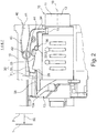
- FIG. 2 shows the recognition element 14 in the retracted position 4.
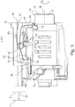
- Die FIGS. 3 to 6 show the recognition element 14 in the extended position 3. If a key is located within the key channel 12, the recognition element 14 occupies the extended position 3. If there is no key in the key channel 12, then the recognition element 14 assumes its retracted position 4.
- the safety lock 30 has a lever element 32 which cooperates with the blocking element 50, in particular with the coupling element 31 and the recognition element 14.
- the lever element 32 is on the one hand arranged to be movable about an axis of rotation 33. If now starting from FIG. 2 a key is inserted into the keyway 12, the recognition element 14 moves from its retracted position 4 in the extended position 3 (see FIG. 3 ). Here, the detection element 14 pushes the lever member 32 upwards, wherein the lever member 32 performs a plurality of movements. On the one hand, a rotation of the lever element 32 takes place about an axis of rotation. Furthermore, the axis of rotation 33 shifts upward along a defined curved path and thus performs a lifting movement. In FIG.
- the lever member 32 While now starting from FIG. 2 the cylinder core 11 rotates about the axis 16, the lever member 32 carries out its above-described movement, wherein at the same time the second end 35, the coupling element 31 contacted on its support surface 38. While now the cylinder core 11 further rotates about the axis 16, there is a further linear movement of the coupling element 31 in the direction of the detection element 14, wherein the lever member 32, starting from FIG. 3 to FIG. 5 maintains its intermediate position immovable.
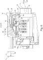
- the coupling element 31 has a recess 37 into which the second end 35 of the lever element 32 in accordance FIG. 6 can enter. In FIG. 6 is the lever member 32 in the locking position 8, in which a movement of the coupling element 31 and the locking element 50 is prevented in the direction of the steering column.
- FIG. 6 takes the blocking element 50 its unlocking position 2, wherein at the same time the safety lock 30 is in the activated state 5.
- the lever member 32 performs with its axis of rotation 33 a lifting movement down.
- a spring element 43 is provided, which exerts a spring force on the lever element 32 in the direction of the cylinder core 11. This is intended that in the retracted position 4 of the detection element 14, the lever member 32 is detached from the coupling element 31 and at the same time there is a contacting of the first end 34 of the lever member 32 with the detection element 14.
- the lever element 32 is mounted in such a way that during the transfer of the blocking element 50 from the locking position 1 into the unlocking position 2, the lever element 32 performs several movements during the movement between the release position 7 and the locking position 8, wherein a first movement is a rotational movement about an axis of rotation and a second movement by a displacement of the lever element 32 along a defined Curved track is determined.
- a first movement is a rotational movement about an axis of rotation and a second movement by a displacement of the lever element 32 along a defined Curved track is determined.
- the lever member 32 can pivot about an axis of rotation and perform a movement, in particular lifting movement with the axis of rotation 33.
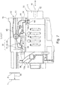
- the lever member 32 is further mounted within the housing 15 such that in the transfer of the locking element 50 of the unlocking position 2, the in FIG. 6 is shown, in the locking position 1, in FIG. 7 is shown, the lever member 32 only performs a movement about the rotation axis 33.
- a corresponding bearing 36 is provided within the housing 15.
- FIG. 6 engages the second end 35 of the lever member 32 in the recess 37 of the coupling element 31 a positive fit.
- the bearing surface 38 which is designed with the recess 37, forms a common component with the coupling element 31.
- the second end 35 is temporarily free of forces and contactless in the recess 37 of the coupling element 31. Since the control member 13, starting from FIG. 5 then turns back by a few degrees about the axis 16, there is a return movement of the coupling element 31 in the direction of the steering column, so that in the locking position 8 finally the second end 35 of the lever member 32 is located in the recess 37 and a contact between the second end 35 of the Lever element 32 is present with a portion of the recess 37. As in FIG. 6 can be seen, the cylinder core 11 with the control member 13 in such a rotational position that a distance between the control member 13 and the coupling element 31 is made. Starting from FIG. 2 to FIG.
- control member 13 is applied to the coupling element 31, so that upon movement of the cylinder core 11 about the axis 16, a corresponding force can be exerted on the locking element 50, so that the locking element 50 can be transferred from the locking position 1 in the unlocked position 2.
- the lever member 32 has a first protrusion 39.1, which is arranged laterally on the lever member 32 and perpendicular to the longitudinal extent of the lever member 32 extends.
- the housing 15 has a mounting opening 40 with a mounting groove 41 and a mounting recess 42 for the first bulge 39.1.
- the first bulge 39.1 moves along the mounting groove 41 until the first bulge 39.1 is transferred into the mounting recess 42 and there its final final assembly position reached.
- a second bulge 39.2 is executed on the lever element 32, which is likewise arranged laterally on the lever element 32 and extends perpendicularly to the longitudinal extent of the lever element 32.
- the second bulge 39.2 is held movably in the bearing 36 of the housing 15. Both bulges 39.1, 39.2 are projecting, running from the lever member 32 extending.
- the first protrusion 39. 1 is arranged offset to the second protrusion 39. 2 on the lever element 32. So that during assembly, the lever member 32 is reliably brought into its final assembly position, the lever member 32 is inserted together with the spring element 43 in the mounting hole 40. During the movement of the lever element 32 along the mounting groove 41, the spring element 43 presses on the lever element 32.
- FIG. 8 shows a further embodiment of the safety lock 30, in contrast to FIG. 2 the second end 35 of the lever member 32 spaced and located in front of the coupling element 31 when the safety lock 30 is in its deactivated state 6.
- a corresponding rotational movement of the lock cylinder 10 to transfer the locking element 50 from the locking position 1 in the unlocked position 2 moves according to FIG. 8 the coupling element 31 in the direction of the second end 35 of the lever member 32. It comes to a contact of the coupling element 31 with the lever member 32 which pivots due to its geometric oblique contour at the second end 35 upwards. Subsequently, the second end 35 of the lever member 32 moves on the support surface 38 until the second end 35 moves into the recess 37 of the coupling element 31, whereby the lever member 32 can assume its locking position 8.
- the embodiment is according to FIG. 8 completely on the embodiment according to FIG. 1 to FIG. 7 applicable.
- the lever member 32 can reliably move between the release position 7 and the locking position 8, is the Force application point of the spring element 43 according to the FIGS. 1 to 8 between the axis of rotation 33 and the first end 34 of the lever element 32nd
Landscapes
- Engineering & Computer Science (AREA)
- Mechanical Engineering (AREA)
- Lock And Its Accessories (AREA)
Claims (13)
- Dispositif de déplacement d'un élément de blocage (50) d'un composant important pour le fonctionnement, en particulier d'une colonne de direction d'un véhicule automobile, doté d'un cylindre de serrure (10) qui présente un noyau de cylindre (11) rotatif avec un canal de clé (12),
un organe de commande (13) disposé sur le cylindre de serrure (10), qui est en liaison active avec l'élément de blocage (50) de telle sorte que lors d'une rotation du noyau de cylindre (11), l'élément de blocage (50) peut être amené dans une position de verrouillage (1) et dans une position de déverrouillage (2), le cylindre de serrure (10) comprenant un élément de détection (14) qui peut être déplacé entre une position sortie (3) et une position rentrée (4), ledit élément de détection (14) se trouvant dans la position rentrée (4) en l'absence de clé dans le canal de clé (12) et l'élément de détection (14) se trouve dans la position sortie (3) lorsqu'une clé est insérée dans le canal de clé (12),
un dispositif de blocage de sécurité (30) étant prévu qui peut être amené dans un état activé (5) et dans un état désactivé (6) et présente un coupleur (31) qui est en liaison active avec l'élément de blocage (50) ainsi qu'avec l'organe de commande (13), dans l'état désactivé (6), le dispositif de blocage de sécurité (30) permettant un mouvement de l'élément de blocage (50) et l'élément de détection(14) se trouvant dans la position rentrée (4) dans laquelle ledit élément de détection(14) est découplé du coupleur (31), et
dans l'état activé (5), le dispositif de blocage de sécurité (30) bloquant un mouvement de l'élément de blocage (50) de la position de déverrouillage (2) vers la position de verrouillage (1) et l'élément de détection (14) se trouvant dans la position sortie (3),
caractérisé en ce que
le dispositif de blocage de sécurité (30) présente un élément de levier (32) qui est disposé de manière déplaçable entre l'élément de détection (14) et le coupleur (31) autour d'un axe de rotation (33),
l'élément de levier (32) pouvant être déplacé, par un mouvement de l'élément de détection (14), entre la position de déblocage (7) et la position de blocage (8), l'élément de levier (32) étant en prise sur l'élément de couplage (31) dans la position de blocage (8),
l'élément de levier (32) permettant un mouvement du coupleur (31) dans la position de déblocage (7) et l'élément de levier (32) étant monté de telle sorte que, lors du mouvement entre la position de déblocage (7) et la position de blocage (8), l'axe de rotation (33) peut être déplacé,
un élément ressort (43) agissant sur l'élément de levier (32), grâce à quoi, dans la position rentrée (4) de l'élément de détection (14), l'élément de levier (32) est détaché de l'élément de couplage (31) et simultanément un contact existant entre une première extrémité (34) de l'élément de levier (32) et l'élément de détection (14), un boîtier (15) est prévu dans lequel sont agencés le dispositif de blocage de sécurité (30) et le cylindre de serrure (10), le boîtier (15) présentant une ouverture de montage (40) pour insérer l'élément de levier (32), ladite ouverture de montage (40) étant conçue avec une géométrie qui sert pour le montage,
l'élément ressort (43) est fixé sur l'ouverture de montage (40) et simultanément en prise sur l'élément de levier (32),
ledit élément de ressort (43) agissant simultanément dans une ouverture (44) de l'élément de levier (32). - Dispositif selon la revendication 1,
caractérisé en ce que
l'élément de levier (32) est monté de telle sorte que lors du transfert de l'élément de blocage (50) de la position de verrouillage (1) vers la position de déverrouillage (2), l'élément de levier (32) exécute, lors du déplacement entre la position de déblocage (7) et la position de blocage (8), au moins deux mouvements, un premier mouvement étant un mouvement rotatif autour de l'axe de rotation (33) et un deuxième mouvement étant déterminé par un déplacement de l'élément de levier (32) le long d'une trajectoire courbe définie, le deuxième mouvement étant notamment un mouvement de translation. - Dispositif selon la revendication 2,
caractérisé en ce que
le premier et le deuxième mouvements sont superposés, du moins en partie. - Dispositif selon l'une quelconque des revendications précédentes,
caractérisé en ce que
l'élément de levier (32) est monté de telle sorte que lors du transfert de l'élément de blocage (50) de la position de déverrouillage (2) vers la position de verrouillage (1), l'élément de levier (32) exécute un seul mouvement, notamment un mouvement rotatif autour de l'axe de rotation (33). - Dispositif selon l'une quelconque des revendications précédentes,
caractérisé en ce qu'
un logement (36) de l'élément de levier (32) est prévu qui rend possible un mouvement de l'élément de levier (32) dans au moins deux directions et/ou en ce que le mouvement de l'élément de levier (32) est un mouvement de rotation et un mouvement de levage. - Dispositif selon l'une quelconque des revendications précédentes,
caractérisé en ce que
l'élément de levier (32) présente une deuxième extrémité (35) qui s'engage par engagement positif avec le coupleur (31) dans l'état activé (5) du dispositif de blocage de sécurité (30) et/ou en ce que le coupleur (31) présente une gorge (37), la deuxième extrémité (35) de l'élément de levier (32) se trouvant dans la gorge (37) dans la position de blocage (8) de l'élément de levier (32). - Dispositif selon l'une quelconque des revendications précédentes,
caractérisé en ce que
le coupleur (31) présente une surface de contact (38), ladite surface de contact (38) se déplaçant, pendant le mouvement de l'élément de blocage (50) entre la position de verrouillage (1) et la position de déverrouillage (2), par rapport à l'élément de levier (32) et un contact étant établi simultanément entre la deuxième extrémité (35) de l'élément de levier (32) et la surface de contact (38), notamment la gorge (37) étant intégrée dans la surface de contact (38). - Dispositif selon l'une quelconque des revendications précédentes,
caractérisé en ce que l'organe de commande (13) présente une came de levage (13a) qui agit sur le coupleur (31) lors d'une rotation du noyau de cylindre (11), au moyen duquel ledit coupleur (31) subissant un mouvement, notamment le coupleur (31) subissant un mouvement translatoire. - Dispositif selon l'une quelconque des revendications précédentes,
caractérisé en ce que
l'élément de levier (32) présente au moins un renflement (39) qui est agencé latéralement sur l'élément de levier (32) et s'étend perpendiculairement au sens longitudinal de l'élément de levier (32), notamment deux renflements (39) étant prévus qui sont chacun disposés sur un côté de l'élément de levier (32). - Dispositif selon l'une quelconque des revendications précédentes,
caractérisé en ce que
l'ouverture de montage (40) présente une rainure de montage (41) et un évidement de montage (42) pour un premier renflement (39) de l'élément de levier (32), le premier renflement (39) étant déplacé, pendant l'insertion de l'élément de levier (32), le long de la rainure de montage jusqu'à ce que le premier renflement (39) soit transféré dans l'évidement de montage (42) et y atteigne la position définitive de montage final. - Dispositif selon l'une quelconque des revendications précédentes,
caractérisé en ce qu'
un deuxième renflement (39) est maintenu de manière à retenue mobile dans le logement (36) du boîtier (15) et/ou en ce que les renflements (39) s'avancent en saillie hors de l'élément de levier (32). - Dispositif selon l'une quelconque des revendications précédentes,
caractérisé en ce que
le premier renflement (39) est décalé par rapport au deuxième renflement (39) sur l'élément de levier (32). - Dispositif selon l'une quelconque des revendications précédentes,
caractérisé en ce qu'
une sécurité anti-retrait de la clé est prévu qui autorise un retrait de la clé hors du canal de clé (12) uniquement dans une position (1, 2) spécifique du noyau de cylindre (11) et/ou en ce que le point d'attaque des forces de l'élément ressort (43) agit sur l'élément de levier (32) entre l'axe de rotation (33) et la première extrémité (34) de l'élément de levier (32).
Applications Claiming Priority (3)
| Application Number | Priority Date | Filing Date | Title |
|---|---|---|---|
| DE102010038160A DE102010038160A1 (de) | 2010-10-13 | 2010-10-13 | Vorrichtung zur Verlagerung eines Sperrelementes |
| PCT/EP2011/067907 WO2012049258A1 (fr) | 2010-10-13 | 2011-10-13 | Dispositif pour monter un élément de blocage |
| EP11768020.7A EP2627542B1 (fr) | 2010-10-13 | 2011-10-13 | Dispositif de déplacement d'un verrou |
Related Parent Applications (1)
| Application Number | Title | Priority Date | Filing Date |
|---|---|---|---|
| EP11768020.7A Division EP2627542B1 (fr) | 2010-10-13 | 2011-10-13 | Dispositif de déplacement d'un verrou |
Publications (2)
| Publication Number | Publication Date |
|---|---|
| EP3208159A1 EP3208159A1 (fr) | 2017-08-23 |
| EP3208159B1 true EP3208159B1 (fr) | 2018-12-12 |
Family
ID=44789479
Family Applications (3)
| Application Number | Title | Priority Date | Filing Date |
|---|---|---|---|
| EP17160552.0A Not-in-force EP3208159B1 (fr) | 2010-10-13 | 2011-10-13 | Dispositif destiné à déplacer un élément de blocage |
| EP11768020.7A Not-in-force EP2627542B1 (fr) | 2010-10-13 | 2011-10-13 | Dispositif de déplacement d'un verrou |
| EP16194223.0A Not-in-force EP3144188B1 (fr) | 2010-10-13 | 2011-10-13 | Dispositif pour déplacer un élément de blocage |
Family Applications After (2)
| Application Number | Title | Priority Date | Filing Date |
|---|---|---|---|
| EP11768020.7A Not-in-force EP2627542B1 (fr) | 2010-10-13 | 2011-10-13 | Dispositif de déplacement d'un verrou |
| EP16194223.0A Not-in-force EP3144188B1 (fr) | 2010-10-13 | 2011-10-13 | Dispositif pour déplacer un élément de blocage |
Country Status (4)
| Country | Link |
|---|---|
| EP (3) | EP3208159B1 (fr) |
| CN (1) | CN103167975B (fr) |
| DE (1) | DE102010038160A1 (fr) |
| WO (1) | WO2012049258A1 (fr) |
Families Citing this family (5)
| Publication number | Priority date | Publication date | Assignee | Title |
|---|---|---|---|---|
| DE102013018835A1 (de) | 2013-09-19 | 2015-03-19 | Huf Hülsbeck & Fürst Gmbh & Co. Kg | Mechanische Lenkungsverriegelung für Fahrzeuge |
| FR3024100B1 (fr) * | 2014-07-23 | 2016-09-09 | U-Shin France Sas | Antivol pour vehicule automobile |
| FR3030407B1 (fr) * | 2014-12-18 | 2018-04-27 | U-Shin France | Dispositif antivol pour colonne de direction |
| US20170158166A1 (en) * | 2015-12-02 | 2017-06-08 | Huf Hülsbeck & Fürst Gmbh & Co. Kg | Locking device |
| JP6798459B2 (ja) * | 2017-09-20 | 2020-12-09 | トヨタ自動車株式会社 | ステアリングロック装置 |
Family Cites Families (17)
| Publication number | Priority date | Publication date | Assignee | Title |
|---|---|---|---|---|
| DE1016095B (de) | 1955-03-18 | 1957-09-19 | Klingelnberg Soehne Ferd | Waelzfraeser und Geraet zur Pruefung seines Profils |
| DE1780228C2 (de) * | 1968-08-17 | 1983-01-13 | DOM-Sicherheitstechnik GmbH & Co KG, 5040 Brühl | Lenk-Zündschloß für Fahrzeuge, insbesondere für Kraftfahrzeuge |
| JPS54143544U (fr) * | 1978-03-28 | 1979-10-05 | ||
| IT1118347B (it) * | 1979-02-13 | 1986-02-24 | Arman Spa | Dispositivo antifurto bloccasterzo per autoveicoli |
| JPS5918932Y2 (ja) * | 1980-04-05 | 1984-05-31 | マツダ株式会社 | ステアリングロツク装置 |
| DE8303073U1 (de) * | 1982-02-12 | 1983-06-23 | Champion Spark Plug Italiana S.p.A., 10040 Druento, Torino | Lenkschloß für Kraftfahrzeuge |
| FR2706392B1 (fr) * | 1993-06-09 | 1995-07-28 | Valeo Securite Habitacle | Antivol de direction pour véhicule automobile. |
| FR2716694B1 (fr) * | 1994-02-28 | 1996-04-19 | Valeo Securite Habitacle | Antivol de direction de véhicule automobile comportant des moyens de blocage du pêne de verrouillage. |
| JP3095328B2 (ja) * | 1994-10-06 | 2000-10-03 | 株式会社東海理化電機製作所 | ステアリングロック装置 |
| US6442985B1 (en) * | 1999-06-11 | 2002-09-03 | Nissan Motor Co., Ltd. | Lock apparatus and lock system |
| DE10016095C2 (de) * | 2000-03-31 | 2002-03-21 | Huf Huelsbeck & Fuerst Gmbh | Lenkschloß für Fahrzeuge, insbesondere Kraftfahrzeuge |
| JP3990224B2 (ja) * | 2002-08-09 | 2007-10-10 | 株式会社ホンダロック | ステアリングロック装置 |
| DE102004053438A1 (de) * | 2004-11-05 | 2006-05-11 | Valeo Sicherheitssysteme Gmbh | Lenkschloß |
| GB2421087A (en) * | 2004-12-09 | 2006-06-14 | Royal Free Hampstead Nhs Trust | Airway inspection device |
| JP4712590B2 (ja) * | 2006-03-29 | 2011-06-29 | 株式会社ユーシン | ステアリングロック装置 |
| JP4819729B2 (ja) * | 2007-03-27 | 2011-11-24 | 株式会社ユーシン | ステアリングロック装置 |
| JP5118077B2 (ja) * | 2009-02-03 | 2013-01-16 | 株式会社東海理化電機製作所 | キー装置 |
-
2010
- 2010-10-13 DE DE102010038160A patent/DE102010038160A1/de not_active Withdrawn
-
2011
- 2011-10-13 EP EP17160552.0A patent/EP3208159B1/fr not_active Not-in-force
- 2011-10-13 WO PCT/EP2011/067907 patent/WO2012049258A1/fr not_active Ceased
- 2011-10-13 EP EP11768020.7A patent/EP2627542B1/fr not_active Not-in-force
- 2011-10-13 CN CN201180049872.1A patent/CN103167975B/zh not_active Expired - Fee Related
- 2011-10-13 EP EP16194223.0A patent/EP3144188B1/fr not_active Not-in-force
Non-Patent Citations (1)
| Title |
|---|
| None * |
Also Published As
| Publication number | Publication date |
|---|---|
| DE102010038160A1 (de) | 2012-04-19 |
| WO2012049258A1 (fr) | 2012-04-19 |
| EP2627542B1 (fr) | 2017-03-15 |
| CN103167975A (zh) | 2013-06-19 |
| EP3144188B1 (fr) | 2018-04-11 |
| EP2627542A1 (fr) | 2013-08-21 |
| DE102010038160A8 (de) | 2012-08-23 |
| CN103167975B (zh) | 2016-06-01 |
| EP3208159A1 (fr) | 2017-08-23 |
| EP3144188A1 (fr) | 2017-03-22 |
Similar Documents
| Publication | Publication Date | Title |
|---|---|---|
| DE112016006079T5 (de) | Fahrzeug-türverriegelungssystem | |
| EP3363972B1 (fr) | Dispositif de verrouillage électrique commutable pour une installation de porte | |
| DE102018009217A1 (de) | Verriegelungseinrichtung mit Zuhaltung für Schutztüren | |
| EP3144188B1 (fr) | Dispositif pour déplacer un élément de blocage | |
| DE102008014636A1 (de) | Lenkradschlosseinrichtung | |
| EP4080102A1 (fr) | Interrupteur de sécurité à gâchette | |
| EP3243712B1 (fr) | Élément de déplacement pour un antivol électrique de direction | |
| DE10335311B4 (de) | Lenkschlossvorrichtung | |
| DE102019122076A1 (de) | Türinnengriffsystem für eine Tür eines Kraftfahrzeugs | |
| EP2418129B1 (fr) | Dispositif de déplacement d'un élément de blocage mobile | |
| EP2136019B1 (fr) | Sous-assemble pour le blocage ou la libération d'une serrure de porte | |
| DE3037959A1 (de) | Kraftfahrzeug-zuendschloss | |
| DE102011051328A1 (de) | Handhabe mit einer Massensperre, die bei einem Unfall verriegelbar ist | |
| EP1301385B1 (fr) | Dispositif de controle mecanique et electrique de systeme de reglage d'appareil de commande d'aiguillage | |
| EP3243713A1 (fr) | Levier de capteur pour un dispositif de détection d'au moins une position de réglage d'un antivol de direction | |
| EP1580352B1 (fr) | Dispositif de commande pour portes ou couvercles | |
| EP2743432B1 (fr) | Poignée pour un dispositif de fermeture d'un véhicule automobile, comprenant une butée de masse inertielle prenant en compte des accélérations actives provenant de différentes directions | |
| EP3392094B1 (fr) | Dispositif de blocage et déblocage d'un composant essentiel au fonctionnement d'un véhicule automobile | |
| DE102013018836A1 (de) | Mechanische Sperrvorrichtung, insbesondere für den Fahrzeugbereich | |
| EP3453579B1 (fr) | Dispositif de verrouillage | |
| EP2536597B1 (fr) | Systeme de direction pour vehicule | |
| EP3575519B1 (fr) | Dispositif de verrouillage électrique commutable pour une installation de porte | |
| EP2314485B1 (fr) | Dispositif de logement d'une unité de verrouillage déplaçable | |
| EP0681950A2 (fr) | Dispositif de levier sélecteur pour une transmission automatique de véhicules automobiles | |
| EP1826077B1 (fr) | Interrupteur d'allumage doté d'une sécurité de manipulation améliorée |
Legal Events
| Date | Code | Title | Description |
|---|---|---|---|
| PUAI | Public reference made under article 153(3) epc to a published international application that has entered the european phase |
Free format text: ORIGINAL CODE: 0009012 |
|
| STAA | Information on the status of an ep patent application or granted ep patent |
Free format text: STATUS: THE APPLICATION HAS BEEN PUBLISHED |
|
| AC | Divisional application: reference to earlier application |
Ref document number: 2627542 Country of ref document: EP Kind code of ref document: P |
|
| AK | Designated contracting states |
Kind code of ref document: A1 Designated state(s): AL AT BE BG CH CY CZ DE DK EE ES FI FR GB GR HR HU IE IS IT LI LT LU LV MC MK MT NL NO PL PT RO RS SE SI SK SM TR |
|
| STAA | Information on the status of an ep patent application or granted ep patent |
Free format text: STATUS: REQUEST FOR EXAMINATION WAS MADE |
|
| STAA | Information on the status of an ep patent application or granted ep patent |
Free format text: STATUS: EXAMINATION IS IN PROGRESS |
|
| 17P | Request for examination filed |
Effective date: 20180223 |
|
| RBV | Designated contracting states (corrected) |
Designated state(s): AL AT BE BG CH CY CZ DE DK EE ES FI FR GB GR HR HU IE IS IT LI LT LU LV MC MK MT NL NO PL PT RO RS SE SI SK SM TR |
|
| 17Q | First examination report despatched |
Effective date: 20180319 |
|
| GRAP | Despatch of communication of intention to grant a patent |
Free format text: ORIGINAL CODE: EPIDOSNIGR1 |
|
| STAA | Information on the status of an ep patent application or granted ep patent |
Free format text: STATUS: GRANT OF PATENT IS INTENDED |
|
| INTG | Intention to grant announced |
Effective date: 20180727 |
|
| GRAS | Grant fee paid |
Free format text: ORIGINAL CODE: EPIDOSNIGR3 |
|
| GRAA | (expected) grant |
Free format text: ORIGINAL CODE: 0009210 |
|
| STAA | Information on the status of an ep patent application or granted ep patent |
Free format text: STATUS: THE PATENT HAS BEEN GRANTED |
|
| AC | Divisional application: reference to earlier application |
Ref document number: 2627542 Country of ref document: EP Kind code of ref document: P |
|
| AK | Designated contracting states |
Kind code of ref document: B1 Designated state(s): AL AT BE BG CH CY CZ DE DK EE ES FI FR GB GR HR HU IE IS IT LI LT LU LV MC MK MT NL NO PL PT RO RS SE SI SK SM TR |
|
| REG | Reference to a national code |
Ref country code: GB Ref legal event code: FG4D Free format text: NOT ENGLISH |
|
| REG | Reference to a national code |
Ref country code: CH Ref legal event code: EP |
|
| REG | Reference to a national code |
Ref country code: AT Ref legal event code: REF Ref document number: 1075527 Country of ref document: AT Kind code of ref document: T Effective date: 20181215 |
|
| REG | Reference to a national code |
Ref country code: DE Ref legal event code: R096 Ref document number: 502011015165 Country of ref document: DE |
|
| REG | Reference to a national code |
Ref country code: IE Ref legal event code: FG4D Free format text: LANGUAGE OF EP DOCUMENT: GERMAN |
|
| REG | Reference to a national code |
Ref country code: NL Ref legal event code: MP Effective date: 20181212 |
|
| REG | Reference to a national code |
Ref country code: LT Ref legal event code: MG4D |
|
| PG25 | Lapsed in a contracting state [announced via postgrant information from national office to epo] |
Ref country code: HR Free format text: LAPSE BECAUSE OF FAILURE TO SUBMIT A TRANSLATION OF THE DESCRIPTION OR TO PAY THE FEE WITHIN THE PRESCRIBED TIME-LIMIT Effective date: 20181212 Ref country code: LV Free format text: LAPSE BECAUSE OF FAILURE TO SUBMIT A TRANSLATION OF THE DESCRIPTION OR TO PAY THE FEE WITHIN THE PRESCRIBED TIME-LIMIT Effective date: 20181212 Ref country code: FI Free format text: LAPSE BECAUSE OF FAILURE TO SUBMIT A TRANSLATION OF THE DESCRIPTION OR TO PAY THE FEE WITHIN THE PRESCRIBED TIME-LIMIT Effective date: 20181212 Ref country code: LT Free format text: LAPSE BECAUSE OF FAILURE TO SUBMIT A TRANSLATION OF THE DESCRIPTION OR TO PAY THE FEE WITHIN THE PRESCRIBED TIME-LIMIT Effective date: 20181212 Ref country code: BG Free format text: LAPSE BECAUSE OF FAILURE TO SUBMIT A TRANSLATION OF THE DESCRIPTION OR TO PAY THE FEE WITHIN THE PRESCRIBED TIME-LIMIT Effective date: 20190312 Ref country code: NO Free format text: LAPSE BECAUSE OF FAILURE TO SUBMIT A TRANSLATION OF THE DESCRIPTION OR TO PAY THE FEE WITHIN THE PRESCRIBED TIME-LIMIT Effective date: 20190312 |
|
| PG25 | Lapsed in a contracting state [announced via postgrant information from national office to epo] |
Ref country code: RS Free format text: LAPSE BECAUSE OF FAILURE TO SUBMIT A TRANSLATION OF THE DESCRIPTION OR TO PAY THE FEE WITHIN THE PRESCRIBED TIME-LIMIT Effective date: 20181212 Ref country code: GR Free format text: LAPSE BECAUSE OF FAILURE TO SUBMIT A TRANSLATION OF THE DESCRIPTION OR TO PAY THE FEE WITHIN THE PRESCRIBED TIME-LIMIT Effective date: 20190313 Ref country code: AL Free format text: LAPSE BECAUSE OF FAILURE TO SUBMIT A TRANSLATION OF THE DESCRIPTION OR TO PAY THE FEE WITHIN THE PRESCRIBED TIME-LIMIT Effective date: 20181212 Ref country code: SE Free format text: LAPSE BECAUSE OF FAILURE TO SUBMIT A TRANSLATION OF THE DESCRIPTION OR TO PAY THE FEE WITHIN THE PRESCRIBED TIME-LIMIT Effective date: 20181212 |
|
| PG25 | Lapsed in a contracting state [announced via postgrant information from national office to epo] |
Ref country code: NL Free format text: LAPSE BECAUSE OF FAILURE TO SUBMIT A TRANSLATION OF THE DESCRIPTION OR TO PAY THE FEE WITHIN THE PRESCRIBED TIME-LIMIT Effective date: 20181212 |
|
| PG25 | Lapsed in a contracting state [announced via postgrant information from national office to epo] |
Ref country code: ES Free format text: LAPSE BECAUSE OF FAILURE TO SUBMIT A TRANSLATION OF THE DESCRIPTION OR TO PAY THE FEE WITHIN THE PRESCRIBED TIME-LIMIT Effective date: 20181212 Ref country code: CZ Free format text: LAPSE BECAUSE OF FAILURE TO SUBMIT A TRANSLATION OF THE DESCRIPTION OR TO PAY THE FEE WITHIN THE PRESCRIBED TIME-LIMIT Effective date: 20181212 Ref country code: PT Free format text: LAPSE BECAUSE OF FAILURE TO SUBMIT A TRANSLATION OF THE DESCRIPTION OR TO PAY THE FEE WITHIN THE PRESCRIBED TIME-LIMIT Effective date: 20190412 Ref country code: IT Free format text: LAPSE BECAUSE OF FAILURE TO SUBMIT A TRANSLATION OF THE DESCRIPTION OR TO PAY THE FEE WITHIN THE PRESCRIBED TIME-LIMIT Effective date: 20181212 Ref country code: PL Free format text: LAPSE BECAUSE OF FAILURE TO SUBMIT A TRANSLATION OF THE DESCRIPTION OR TO PAY THE FEE WITHIN THE PRESCRIBED TIME-LIMIT Effective date: 20181212 |
|
| PG25 | Lapsed in a contracting state [announced via postgrant information from national office to epo] |
Ref country code: SK Free format text: LAPSE BECAUSE OF FAILURE TO SUBMIT A TRANSLATION OF THE DESCRIPTION OR TO PAY THE FEE WITHIN THE PRESCRIBED TIME-LIMIT Effective date: 20181212 Ref country code: SM Free format text: LAPSE BECAUSE OF FAILURE TO SUBMIT A TRANSLATION OF THE DESCRIPTION OR TO PAY THE FEE WITHIN THE PRESCRIBED TIME-LIMIT Effective date: 20181212 Ref country code: EE Free format text: LAPSE BECAUSE OF FAILURE TO SUBMIT A TRANSLATION OF THE DESCRIPTION OR TO PAY THE FEE WITHIN THE PRESCRIBED TIME-LIMIT Effective date: 20181212 Ref country code: RO Free format text: LAPSE BECAUSE OF FAILURE TO SUBMIT A TRANSLATION OF THE DESCRIPTION OR TO PAY THE FEE WITHIN THE PRESCRIBED TIME-LIMIT Effective date: 20181212 Ref country code: IS Free format text: LAPSE BECAUSE OF FAILURE TO SUBMIT A TRANSLATION OF THE DESCRIPTION OR TO PAY THE FEE WITHIN THE PRESCRIBED TIME-LIMIT Effective date: 20190412 |
|
| REG | Reference to a national code |
Ref country code: DE Ref legal event code: R097 Ref document number: 502011015165 Country of ref document: DE |
|
| PLBE | No opposition filed within time limit |
Free format text: ORIGINAL CODE: 0009261 |
|
| STAA | Information on the status of an ep patent application or granted ep patent |
Free format text: STATUS: NO OPPOSITION FILED WITHIN TIME LIMIT |
|
| PG25 | Lapsed in a contracting state [announced via postgrant information from national office to epo] |
Ref country code: SI Free format text: LAPSE BECAUSE OF FAILURE TO SUBMIT A TRANSLATION OF THE DESCRIPTION OR TO PAY THE FEE WITHIN THE PRESCRIBED TIME-LIMIT Effective date: 20181212 Ref country code: DK Free format text: LAPSE BECAUSE OF FAILURE TO SUBMIT A TRANSLATION OF THE DESCRIPTION OR TO PAY THE FEE WITHIN THE PRESCRIBED TIME-LIMIT Effective date: 20181212 |
|
| 26N | No opposition filed |
Effective date: 20190913 |
|
| PG25 | Lapsed in a contracting state [announced via postgrant information from national office to epo] |
Ref country code: TR Free format text: LAPSE BECAUSE OF FAILURE TO SUBMIT A TRANSLATION OF THE DESCRIPTION OR TO PAY THE FEE WITHIN THE PRESCRIBED TIME-LIMIT Effective date: 20181212 |
|
| PG25 | Lapsed in a contracting state [announced via postgrant information from national office to epo] |
Ref country code: MC Free format text: LAPSE BECAUSE OF FAILURE TO SUBMIT A TRANSLATION OF THE DESCRIPTION OR TO PAY THE FEE WITHIN THE PRESCRIBED TIME-LIMIT Effective date: 20181212 |
|
| REG | Reference to a national code |
Ref country code: CH Ref legal event code: PL |
|
| PG25 | Lapsed in a contracting state [announced via postgrant information from national office to epo] |
Ref country code: LU Free format text: LAPSE BECAUSE OF NON-PAYMENT OF DUE FEES Effective date: 20191013 Ref country code: CH Free format text: LAPSE BECAUSE OF NON-PAYMENT OF DUE FEES Effective date: 20191031 Ref country code: LI Free format text: LAPSE BECAUSE OF NON-PAYMENT OF DUE FEES Effective date: 20191031 |
|
| REG | Reference to a national code |
Ref country code: BE Ref legal event code: MM Effective date: 20191031 |
|
| PG25 | Lapsed in a contracting state [announced via postgrant information from national office to epo] |
Ref country code: BE Free format text: LAPSE BECAUSE OF NON-PAYMENT OF DUE FEES Effective date: 20191031 |
|
| GBPC | Gb: european patent ceased through non-payment of renewal fee |
Effective date: 20191013 |
|
| PG25 | Lapsed in a contracting state [announced via postgrant information from national office to epo] |
Ref country code: IE Free format text: LAPSE BECAUSE OF NON-PAYMENT OF DUE FEES Effective date: 20191013 Ref country code: GB Free format text: LAPSE BECAUSE OF NON-PAYMENT OF DUE FEES Effective date: 20191013 |
|
| REG | Reference to a national code |
Ref country code: AT Ref legal event code: MM01 Ref document number: 1075527 Country of ref document: AT Kind code of ref document: T Effective date: 20191013 |
|
| PG25 | Lapsed in a contracting state [announced via postgrant information from national office to epo] |
Ref country code: AT Free format text: LAPSE BECAUSE OF NON-PAYMENT OF DUE FEES Effective date: 20191013 |
|
| PGFP | Annual fee paid to national office [announced via postgrant information from national office to epo] |
Ref country code: DE Payment date: 20201031 Year of fee payment: 10 Ref country code: FR Payment date: 20201020 Year of fee payment: 10 |
|
| PG25 | Lapsed in a contracting state [announced via postgrant information from national office to epo] |
Ref country code: CY Free format text: LAPSE BECAUSE OF FAILURE TO SUBMIT A TRANSLATION OF THE DESCRIPTION OR TO PAY THE FEE WITHIN THE PRESCRIBED TIME-LIMIT Effective date: 20181212 |
|
| PG25 | Lapsed in a contracting state [announced via postgrant information from national office to epo] |
Ref country code: HU Free format text: LAPSE BECAUSE OF FAILURE TO SUBMIT A TRANSLATION OF THE DESCRIPTION OR TO PAY THE FEE WITHIN THE PRESCRIBED TIME-LIMIT; INVALID AB INITIO Effective date: 20111013 Ref country code: MT Free format text: LAPSE BECAUSE OF FAILURE TO SUBMIT A TRANSLATION OF THE DESCRIPTION OR TO PAY THE FEE WITHIN THE PRESCRIBED TIME-LIMIT Effective date: 20181212 |
|
| REG | Reference to a national code |
Ref country code: DE Ref legal event code: R119 Ref document number: 502011015165 Country of ref document: DE |
|
| PG25 | Lapsed in a contracting state [announced via postgrant information from national office to epo] |
Ref country code: MK Free format text: LAPSE BECAUSE OF FAILURE TO SUBMIT A TRANSLATION OF THE DESCRIPTION OR TO PAY THE FEE WITHIN THE PRESCRIBED TIME-LIMIT Effective date: 20181212 |
|
| PG25 | Lapsed in a contracting state [announced via postgrant information from national office to epo] |
Ref country code: DE Free format text: LAPSE BECAUSE OF NON-PAYMENT OF DUE FEES Effective date: 20220503 |
|
| PG25 | Lapsed in a contracting state [announced via postgrant information from national office to epo] |
Ref country code: FR Free format text: LAPSE BECAUSE OF NON-PAYMENT OF DUE FEES Effective date: 20211031 |