EP4080102A1 - Interrupteur de sécurité à gâchette - Google Patents
Interrupteur de sécurité à gâchette Download PDFInfo
- Publication number
- EP4080102A1 EP4080102A1 EP22168353.5A EP22168353A EP4080102A1 EP 4080102 A1 EP4080102 A1 EP 4080102A1 EP 22168353 A EP22168353 A EP 22168353A EP 4080102 A1 EP4080102 A1 EP 4080102A1
- Authority
- EP
- European Patent Office
- Prior art keywords
- safety switch
- bulkhead
- locking
- switch according
- actuator
- Prior art date
- Legal status (The legal status is an assumption and is not a legal conclusion. Google has not performed a legal analysis and makes no representation as to the accuracy of the status listed.)
- Granted
Links
Images


Classifications
-
- E—FIXED CONSTRUCTIONS
- E05—LOCKS; KEYS; WINDOW OR DOOR FITTINGS; SAFES
- E05B—LOCKS; ACCESSORIES THEREFOR; HANDCUFFS
- E05B17/00—Accessories in connection with locks
- E05B17/22—Means for operating or controlling lock or fastening device accessories, i.e. other than the fastening members, e.g. switches, indicators
-
- E—FIXED CONSTRUCTIONS
- E05—LOCKS; KEYS; WINDOW OR DOOR FITTINGS; SAFES
- E05B—LOCKS; ACCESSORIES THEREFOR; HANDCUFFS
- E05B47/00—Operating or controlling locks or other fastening devices by electric or magnetic means
- E05B47/0001—Operating or controlling locks or other fastening devices by electric or magnetic means with electric actuators; Constructional features thereof
- E05B47/0002—Operating or controlling locks or other fastening devices by electric or magnetic means with electric actuators; Constructional features thereof with electromagnets
- E05B47/0003—Operating or controlling locks or other fastening devices by electric or magnetic means with electric actuators; Constructional features thereof with electromagnets having a movable core
- E05B47/0004—Operating or controlling locks or other fastening devices by electric or magnetic means with electric actuators; Constructional features thereof with electromagnets having a movable core said core being linearly movable
-
- E—FIXED CONSTRUCTIONS
- E05—LOCKS; KEYS; WINDOW OR DOOR FITTINGS; SAFES
- E05B—LOCKS; ACCESSORIES THEREFOR; HANDCUFFS
- E05B47/00—Operating or controlling locks or other fastening devices by electric or magnetic means
- E05B47/0001—Operating or controlling locks or other fastening devices by electric or magnetic means with electric actuators; Constructional features thereof
-
- E—FIXED CONSTRUCTIONS
- E05—LOCKS; KEYS; WINDOW OR DOOR FITTINGS; SAFES
- E05B—LOCKS; ACCESSORIES THEREFOR; HANDCUFFS
- E05B15/00—Other details of locks; Parts for engagement by bolts of fastening devices
-
- E—FIXED CONSTRUCTIONS
- E05—LOCKS; KEYS; WINDOW OR DOOR FITTINGS; SAFES
- E05B—LOCKS; ACCESSORIES THEREFOR; HANDCUFFS
- E05B17/00—Accessories in connection with locks
- E05B17/20—Means independent of the locking mechanism for preventing unauthorised opening, e.g. for securing the bolt in the fastening position
- E05B17/2007—Securing, deadlocking or "dogging" the bolt in the fastening position
- E05B17/203—Securing, deadlocking or "dogging" the bolt in the fastening position not following the movement of the bolt
- E05B17/2038—Securing, deadlocking or "dogging" the bolt in the fastening position not following the movement of the bolt moving rectilinearly
-
- E—FIXED CONSTRUCTIONS
- E05—LOCKS; KEYS; WINDOW OR DOOR FITTINGS; SAFES
- E05B—LOCKS; ACCESSORIES THEREFOR; HANDCUFFS
- E05B47/00—Operating or controlling locks or other fastening devices by electric or magnetic means
- E05B47/06—Controlling mechanically-operated bolts by electro-magnetically-operated detents
- E05B47/0603—Controlling mechanically-operated bolts by electro-magnetically-operated detents the detent moving rectilinearly
-
- E—FIXED CONSTRUCTIONS
- E05—LOCKS; KEYS; WINDOW OR DOOR FITTINGS; SAFES
- E05B—LOCKS; ACCESSORIES THEREFOR; HANDCUFFS
- E05B47/00—Operating or controlling locks or other fastening devices by electric or magnetic means
- E05B2047/0048—Circuits, feeding, monitoring
- E05B2047/0067—Monitoring
- E05B2047/0068—Door closed
-
- E—FIXED CONSTRUCTIONS
- E05—LOCKS; KEYS; WINDOW OR DOOR FITTINGS; SAFES
- E05B—LOCKS; ACCESSORIES THEREFOR; HANDCUFFS
- E05B63/00—Locks or fastenings with special structural characteristics
- E05B2063/0026—Elongated, e.g. stud-like, striker entering into an opening in which movable detent means engage the elongated striker
-
- F—MECHANICAL ENGINEERING; LIGHTING; HEATING; WEAPONS; BLASTING
- F16—ENGINEERING ELEMENTS AND UNITS; GENERAL MEASURES FOR PRODUCING AND MAINTAINING EFFECTIVE FUNCTIONING OF MACHINES OR INSTALLATIONS; THERMAL INSULATION IN GENERAL
- F16P—SAFETY DEVICES IN GENERAL; SAFETY DEVICES FOR PRESSES
- F16P3/00—Safety devices acting in conjunction with the control or operation of a machine; Control arrangements requiring the simultaneous use of two or more parts of the body
- F16P3/08—Safety devices acting in conjunction with the control or operation of a machine; Control arrangements requiring the simultaneous use of two or more parts of the body in connection with the locking of doors, covers, guards, or like members giving access to moving machine parts
Definitions
- the present invention relates to a safety switch and a safety circuit arrangement with a safety switch and an actuator.
- Safety switches and corresponding safety circuit arrangements are used in safety technology in order to reduce the hazards emanating from machines and technical systems to an acceptable level for people.
- safety circuit arrangements are used to secure access to a hazardous area, for example on a protective door which, as a separating protective device, secures access to the hazardous area.
- the safety switch can only release the operation of a hazardous system within the hazardous area if the safety circuit arrangement can ensure that the protective door is properly locked.
- the system can be enabled via a safety controller which is coupled to the safety circuit arrangement and receives corresponding safety-related control signals from the safety circuit arrangement.
- Safety circuit arrangements of this type are subject to normative specifications that prescribe a defined fail-safety of the safety circuit arrangement.
- the required fail-safety can be achieved by additional, safety-related devices on the safety circuit arrangement.
- a transmitter and a receiver which are arranged on the actuator and the safety switch, interact in such a way that they ensure the presence of the actuator in a defined locked position relative to the safety switch.
- a guard locking device can also be provided in a safety circuit arrangement of the type mentioned.
- the guard locking means that not only is a position of a safety-relevant, moving component monitored, but it is also locked in a defined position.
- a tumbler is, for example, from DE 10 2009 041 101 A1 or WO 2016/058718 A1 known.
- a tumbler pin can be moved between a release position and a locking position by means of a rotary drive, the tumbler pin and the drive being kinematically coupled to one another via a transmission device.
- EP 3 474 304 A1 shows a safety switch with a small and compact design.
- the safety switch according to EP 3 474 304 A1 has no locking pin. Rather, a locking unit is provided in which a blocking element projects into an opening of the locking unit in the locking position in order to reduce the size of the opening.
- An actuator whose front end has a cross-sectional area that is larger than this reduced opening but smaller than the opening alone can thus be held in the locking unit.
- the blocking element can be deflected against a contact force, so that the actuator can pass through the opening, and as soon as the actuator is introduced into its locking position, the contact force pushes the blocking element back into the locking position transferred and fixed the actuator.
- the blocking element can be locked via an additional locking unit so that it can no longer be deflected against the contact force.
- tumblers have the disadvantage that the bolt is always kinematically coupled to the respective drive and thus a force acting on the bolt is also transmitted to the drive.
- the device after EP 3 474 304 A1 decouples the blocking element and guard locking, but is limited to certain types of actuator.
- a safety switch having: a movably mounted locking bolt, which is set up to arrest an actuator in a defined locking position relative to the safety switch, and a movably mounted barrier bulkhead, which can be switched between a first position and a second Position is movable, wherein the barrier bulkhead is set up to fix the movably mounted locking pin via a form fit in the second position.
- a safety switch with a locking bolt that can be locked via a movable locking bulkhead.
- the barrier bulkhead blocks movement of the locking bolt via a positive fit in the second position and absorbs forces acting on the locking bolt. Forces on the locking bolts, which arise, for example, when attempting to open a protective door against the tumbler, can in this way be diverted to the structure of the safety switch, in particular to the housing, without these forces affecting an adjustment element of the bolt or a drive of the bulkhead can be transferred.
- a drive can then be designed for a lower load and operated with less energy, as a result of which the safety switch can be made smaller, more compact and cheaper overall.
- a corresponding actuator Since the locking takes place via a bolt, there are many possibilities for the design of a corresponding actuator or the way in which an actuator can be combined with the safety switch.
- the shape of the actuator only has to be set up so that the bolt can engage in it, with any angle at which the actuator is brought up to the safety switch radially with respect to the bolt being able to be used.
- a safety circuit arrangement made up of safety switch and actuator can also be used more flexibly in this way.
- the structural separation of the bolt for the tumbler and its locking by the bulkhead also has the advantage that both devices only have to be designed for their respective purpose and can therefore be designed to be particularly effective.
- the locking pin can be mounted in a guide body that has a recess through which the barrier bulkhead can be moved in the guide body, and the form fit between the barrier bulkhead and the guide body is formed.
- the bulkhead can thus be pushed into the guide body of the locking bolt in order to block the locking bolt.
- a force acting on the bulkhead via the bolt is transmitted through the bulkhead to the guide body and thus to a structural element of the safety switch.
- a drive of the bolt and a drive of the bulkhead can be decoupled from this force in this way.
- a very short bulkhead is sufficient, which only has to bridge a short movement distance from the first position to the second position.
- a drive device for the barrier bulkhead can also be designed to be simple and compact.
- the safety switch also has a transmission element which is set up to move the bulkhead transversally, in particular perpendicularly, to the longitudinal direction of the transmission element from the first position into the second position during a movement running in a longitudinal direction of the transmission element.
- the transmission element By means of the transmission element, it is possible to carry out a lateral movement in order to position the bulkhead, which movement can take place essentially parallel to the movement of the locking pin. This makes it possible for the safety switch to extend essentially in a longitudinal direction of the locking bolt, as a result of which a particularly narrow configuration of the safety switch becomes possible.
- the transmission element also makes it possible to decouple a drive of the bulkhead from the bulkhead. In other words, the transmission element and the bulkhead can be set up in such a way that a force acting on the bulkhead is not transmitted to a drive of the transmission element.
- the transmission element can have a first projection that rises in a first direction transverse to the longitudinal direction of the transmission element, and a second projection that rises in a second direction opposite to the first direction and in the longitudinal direction relative to offset from the first projection.
- a lifting and lowering movement of the bulkhead transversely to the longitudinal direction of the transmission element can be achieved in a simple manner via the projections, without additional components being required for this.
- a force decoupling can be realized in a simple manner by this type of force deflection.
- the safety switch can also have a drive which is set up to move the bulkhead from the first position into the second position.
- the drive enables controlled guard locking of the safety switch. Due to the short distance that a barrier bulkhead described here has to cover in order to lock the bolt, the drive for the bulkhead can be designed to be very simple, small and energy-saving.
- the drive can be an electromechanical actuator, in particular a lifting magnet, which is set up to carry out a first linear movement along a defined direction of movement.
- the drive can thus be a simple lifting device, which can be configured particularly favorably if only a small stroke is to be exercised. In the present case, this is possible due to the appropriate configuration of the bulkhead.
- the locking bolt can be set up to carry out a second linear movement along the defined direction of movement.
- the directions of movement of the bolt and of the drive therefore correspond.
- the safety switch it is possible for the safety switch to extend essentially in a longitudinal direction and thus be as narrow as possible.
- the locking pin and the drive are force-decoupled.
- This refinement contributes to the fact that the drive can be configured in a particularly economical and simple manner, since the drive does not have to compensate for locking forces acting on the locking pin, since these are decoupled via the form fit.
- the safety switch can have an actuating element with an application force, which pretensions the locking bolt in a locking position.
- the safety switch has a pre-centering.
- Pre-centering means that an actuator is held in a position suitable for locking without it already being locked.
- the pre-centering means that the locking bolt itself does not have to be moved again for the actual locking, since it is already in a locking position. For a final locking, only a movement of the locking bolt against the contact force must be prevented.
- the safety switch can also have an additional unlocking device, via which the bulkhead can be moved from the first position into the second position.
- the additional unlocking device can serve as an auxiliary unlocking device and enable manual unlocking. It is also conceivable to further develop the manual release into an emergency release. The advantage here is that the additional unlocking device also only has to be set up to move the bulkhead. An auxiliary or emergency unlocking can thus be implemented in a simple manner.
- the safety switch can also have a reading unit which is set up to read out signals from a corresponding transponder of the actuator when the actuator is in the locked position.
- the position of the actuator can be easily verified via a transponder contained in the actuator.
- the transponder/reader combination can ensure that the normative specifications for a safety switch are met. Since the actuator can be flexible according to the embodiment according to the invention, the transponder/reading unit combination can also be variable.
- the safety switch can also have a receptacle into which the actuator can be inserted in order to assume the locking position, the receptacle having an opening angle of 180° at which the actuator can be inserted into the receptacle.
- the safety circuit arrangement can be configured flexibly and the safety switch can be arranged in different alignments with respect to the actuator.
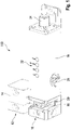
- FIG. 1 shows a perspective view of an embodiment of a safety circuit arrangement.
- the safety circuit arrangement is denoted here in its entirety by the reference numeral 100 and essentially comprises two mutually movable, interacting components: safety switch 10 and actuator 12.
- Actuator 12 includes a mounting part 14, via which actuator 12 can be connected to a safety-relevant, moving component, for example a protective door, and an actuating part 16, which can be brought into an operative connection with safety switch 10 depending on a position of the safety-relevant, moving component is.
- a safety-relevant, moving component for example a protective door
- actuating part 16 which can be brought into an operative connection with safety switch 10 depending on a position of the safety-relevant, moving component is.
- the safety switch 10 comprises a housing with a base body 18 which can be fastened to a device which is stationary relative to the movable component, for example a door frame, and has a receptacle 20 into which the actuating part 16 of the actuator 12 can be inserted in order to establish the operative connection.
- the effective connection can include locking monitoring and guard locking.
- a state of the operative connection can be visualized via display elements 22 on the base body 18 .
- the status can also be reported to other devices, in particular to a safety controller, via an interface 24 in order to trigger a reaction depending on the status detected by the safety switch 10 .
- a safety controller can prevent the operation of a technical system if the actuator part 16 is not correctly detected in the receptacle 20 .
- the safety switch 10 also includes an auxiliary unlocking device 26, via which an auxiliary or emergency unlocking of the actuator 12 is possible.
- auxiliary unlocking device 26 As will be explained in more detail below, a tumbler can be manually released by the safety switch 10 via the auxiliary unlocking device 26 .
- FIG. 12 shows a cross-sectional view of the safety switch 10.
- FIG 1 longitudinally through the body 18.
- the same reference numerals designate the same parts as in relation to FIG 1 .
- the actuator 12 is in the 2 , as already in relation to 1 shown in the locked position relative to the safety switch 10, in which the actuating part 16 is positioned in the receptacle 20 of the safety switch 10 such that a proper locking of the safety-relevant moving component in relation to the stationary component to which the safety switch 10 is attached can be assumed .
- the correct position of the actuating part 16 in the receptacle 20 can be implemented, for example, as indicated here, via a transponder 28 in the actuating part 16 and a corresponding reading unit 29 in the safety switch 10.
- the safety switch 10 is not limited to this design of the locking monitor and other options for determining the position of the actuating part relative to the safety switch 10 are conceivable.
- the actuator part 16 can be locked in the receptacle 20 by the safety switch 10, so that the safety-relevant, moving component can no longer be moved in relation to the stationary component (guard locking).
- the safety switch 10 has a movably mounted locking bolt 30 which can be engaged with the actuating part 16 .
- the actuation part 16 can have a recess 32 in the form of a hole, as shown here, or in the form of an engagement trough, into which the locking pin 30 engages in order to fix the actuation part 16 in place. A simple intervention is sufficient for fixing and there is no need to reach behind the actuating part 16 .
- the receptacle 20 can, for example, as shown here, be slot-like, with a 180° wide opening angle for receiving the actuating part 16.
- the receptacle 20 can, for example, have a closing surface 34, which extends orthogonally to a longitudinal axis 36 of the bolt body, a the bolt 30 opposite stop 38 and the stop 38 with the base body 18 connecting web 40 may be formed.
- a two-part receptacle 20 is also conceivable, in which the stop 38 is detached from the base body 18 . In this case, it would be conceivable for the actuating part 16 to be fed in at a 360° angle radially to the locking pin 30 .
- the locking bolt 30 can be a cylindrical body which has a rounded head part 42 and which ends in a radially projecting flange part 44 on a side opposite the head part 42 .
- the locking pin 30 can be movably mounted in a guide 46 along the longitudinal axis 36 of its body. The locking pin 30 can be moved from a locking position, in which the locking pin 30 projects into the closing surface 34, and a release position, in which the locking pin 30 releases the actuating part 16.
- the flange part 44 can be arranged in a hollow-cylindrical guide body 48, with an upper stop 50 and a lower stop 52 of the guide body 48 defining a movement path 54 over the length of which the locking pin 30 can be moved between the two positions.
- a closing spring 56 biases the locking pin for movement into the locked position.
- the flange part 44 and the guide body 48 can each have corresponding opposite bores 58 for receiving and supporting the closing spring 56 .
- the closing spring 56 can be designed in such a way that it exerts a force on the locking pin 30 which is sufficient for pre-centering the actuating part 16 but does not block it in such a way that the actuating part can no longer be moved out of the locking position. Rather, a spring force of the closing spring 56 can be selected such that a person can pull the pre-centered actuating part 16 out of the receptacle 20 with normal exertion.
- the safety switch 10 also has a bulkhead 60 which is set up to fix the movably mounted locking pin 30 at least in its locked position.
- the barrier bulkhead 60 can be a quickly displaceable closure which can be introduced into the movement path 54 of the locking bolt 30 transversely, in particular perpendicularly, to the longitudinal body axis 36 of the locking bolt 30 .
- the barrier bulkhead 60 can be pushed into the guide body 48 through a radial recess 62 in the latter in order to assume a first position (blocked position).
- the locking bulkhead 60 blocks a movement of the locking pin 30 via a form fit.
- the form fit can be formed by the interlocking of the barrier bulkhead 60 with the flange part 44 and a stop surface 64 of the guide body 48 .
- a force that presses on the locking pin 30 in the longitudinal direction against the contact force of the closing spring 56 acts normal to a locking surface 66 of the locking bulkhead 60 , with a surface opposite the locking surface 66 abutting the stop surface 64 of the guide body 48 .
- the guide body 48 which absorbs a force acting on the locking pin 30 via the bulkhead 60, can be mounted firmly in the base body 18 and is therefore rigidly connected to the component to which the housing together with the base body 18 is attached.
- the movement of the locking bolt 30 is released, so that it can move in the guide body 48 along the longitudinal axis 36 of the body.
- the actuator part 16 can be pulled out of the receptacle 20, with the locking pin 30 being pressed against the loading force of the closing spring.
- the bulkhead 60 can lock the locking pin 30 in the locked position. It is also conceivable that in another embodiment the barrier bulkhead 60 also holds the locking pin 30 in a release position, ie in a position in which the locking pin 30 does not protrude through the closing surface 34 .
- the locking bolt 30 and the locking bulkhead 60 can be set up in such a way that the locking bulkhead 60 engages in the flange part 44 in order to hold the locking bolt 30 against the contact force of the closing spring 56 .
- the barrier bulkhead 60 can interact with the guide body 48 in such a way that a force on the locking pin 30 caused by the contact force is intercepted via a form fit.
- the barrier bulkhead 60 can be moved transversely, in particular perpendicularly, to the longitudinal body axis 36 of the locking pin 30 .
- a driving force for moving the barrier bulkhead 60 can be provided by a drive 68 which is coupled to the barrier bulkhead 60 by means of a transmission element 70 .
- the transmission element 70 can be set up to execute a linear movement driven by the drive 68 and to transmit this movement to the bulkhead 60 .
- the drive 68 can, as in 2 indicated, be a lifting magnet, in particular a bistable lifting magnet, which can set a plunger 72 in a linear movement.
- the plunger 72 ends here in a radially projecting head part 74 which engages in a receptacle 76 on a lower section 68 of the transmission element 70 in order to transmit the linear movement of the drive 68 to the transmission element 70 .
- a movement of the transmission element 70 can take place essentially parallel to the body longitudinal axis 36 of the locking bolt 30 .
- the transmission element 70 can be mounted in a guide 80 running parallel to the guide body 48 .
- the transmission element 70 can move the locking bulkhead 60 transversely to the body longitudinal axis 36 of the locking bolt 30 in order to lock it, as described above.
- the bulkhead 60 can be mounted in such a way that it can only move along this transverse axis 82, with forces acting on the bulkhead 60 transverse to this axis being absorbed by the mounting.
- the locking bolt 30, the locking bulkhead 60 and the transmission element 70 can be force-decoupled with an appropriate choice of storage.
- the bulkhead 60 can be supported, for example, by the recess 62 in the guide body 48 .
- the transmission element 70 can have projections 84 and 86 which extend transversely to the linear direction of movement of the transmission element 70 .
- the projections 84, 86 can, for example, be designed in the form of rounded cams and interact with the blocking bulkhead 60 so that this selectively assumes the blocking position or the release position when the transmission element is moved in the lateral direction.
- the bulkhead 60 can have an opening 88 through which the transmission element 70 is guided in the longitudinal direction, with the projections 84, 86 deflecting the bulkhead 60 in the direction in which the projections extend.
- a distance over which the bulkhead 60 can be deflected i.e. the distance between the first position and the second position, can be very small, for example less than 5 mm.
- the bulkhead 60 can be mounted freely, so that only little force is required for the movement from the first position to the second position. Accordingly, a small and very compact drive 68 can be sufficient to ensure effective guard locking.
- the safety switch 10 can be designed very small and compact due to the small size of the drive 68 and the simple blocking mechanism.
- the drive 68 requires only little energy in order to enable effective guard locking with this structure.
- the safety switch 10 also has an auxiliary unlocking device 26 which provides an additional unlocking option.
- the safety switch 10 can be unlocked manually via the auxiliary unlocking device 26 with the aid of a tool, for example a wrench or a square key.
- the auxiliary unlocking device 26 is coupled to the transmission element 70 at its lower section 78, with a rotational movement of the auxiliary unlocking device 26 being converted into the previously described linear movement of the transmission element 70.
- the linear movement in turn, moves the blocking bulkhead 60 from the blocking position to the unblocking position in the manner previously described.
- the drive 68 since the drive 68 only has to be designed to apply a force for moving the barrier bulkhead, but is otherwise force-decoupled from the locking bolt, the manual unlocking can be actuated directly against the driving force of the drive 68 in this embodiment.
- the tumbler described here via a bulkhead 60 thus allows, in contrast to known safety switches, a particularly simple configuration of an auxiliary and / or emergency release, since no additional Decoupling of the drive 68 must be provided. As a result, the structure of the safety switch 10 can be simplified even further.
- Electronics 90 can be provided for monitoring the locking by the transponder 28 and the reading unit 29 , for visualizing a state of the safety switch 10 by means of the display elements 22 and for controlling the drive 68 .
- the electronics which can include integrated and discrete components, are arranged on a single printed circuit board 92 here.
- the printed circuit board 92 extends essentially in a longitudinal direction of the safety switch 10 directly along an upper side 94 of the housing of the safety switch 10. This positioning has the advantage that all the essentially electrical components of the safety switch 10 can be arranged on a printed circuit board. This includes, on the one hand, the reading unit 29, the display elements 22, a drive controller 96 and a sensor system 98 for detecting the respective operating state of the tumbler.
- the sensor system 98 can be a light barrier, for example, whose light beam is interrupted depending on the position of the transmission element 70 .
- FIG. 1 shows a cross-sectional view of the safety circuit arrangement 100 described above.
- the same reference numbers here again designate the same parts as previously in FIG 1 and 2 .
- the sectional plane here is a normal plane to the longitudinal body axis 36 of the locking bolt 30 and runs through the locking bulkhead 60.
- the locking bulkhead 60 is also in the locked position in this illustration, in which movement of the locking bolt 30 is blocked.
- the locking bolt 30 is mounted in the guide body 48 in such a way that the bolt 30 can move along its longitudinal axis 36 .
- the bulkhead 60 is movably mounted in a recess 62 of the guide body 48 and can be moved transversely to the longitudinal axis 36 of the body.
- the barrier bulkhead 60 has an opening 88 through which the transmission element 70 is passed through.
- the transmission element 70 can be moved parallel to the longitudinal axis 36 of the body.
- the projections 84 and 86 move the barrier bulkhead 60 either into the blocked position or into the release position. Additional stops on the guide body 48 prevent the bulkhead from being pushed too far into the guide body 48 .
- the bulkhead 60 is not limited to the form shown here, but that other variants are conceivable as to how the bulkhead 60 can be configured. It is essential that the barrier bulkhead 60 can engage in a movement path of the locking bolt 30 in such a way that its movement is blocked by a form fit.
- the form fit can be formed with the guide body 48 .
Landscapes
- Engineering & Computer Science (AREA)
- General Engineering & Computer Science (AREA)
- Mechanical Engineering (AREA)
- Physics & Mathematics (AREA)
- Electromagnetism (AREA)
- Switch Cases, Indication, And Locking (AREA)
- Lock And Its Accessories (AREA)
Applications Claiming Priority (1)
| Application Number | Priority Date | Filing Date | Title |
|---|---|---|---|
| DE102021109993.5A DE102021109993B3 (de) | 2021-04-20 | 2021-04-20 | Sicherheitsschalter mit Zuhaltung |
Publications (3)
| Publication Number | Publication Date |
|---|---|
| EP4080102A1 true EP4080102A1 (fr) | 2022-10-26 |
| EP4080102C0 EP4080102C0 (fr) | 2024-01-24 |
| EP4080102B1 EP4080102B1 (fr) | 2024-01-24 |
Family
ID=81449175
Family Applications (1)
| Application Number | Title | Priority Date | Filing Date |
|---|---|---|---|
| EP22168353.5A Active EP4080102B1 (fr) | 2021-04-20 | 2022-04-14 | Interrupteur de sécurité à gâchette |
Country Status (5)
| Country | Link |
|---|---|
| US (1) | US20220333407A1 (fr) |
| EP (1) | EP4080102B1 (fr) |
| JP (1) | JP2022165923A (fr) |
| CN (1) | CN115217367A (fr) |
| DE (1) | DE102021109993B3 (fr) |
Cited By (1)
| Publication number | Priority date | Publication date | Assignee | Title |
|---|---|---|---|---|
| EP4361491A1 (fr) * | 2022-10-28 | 2024-05-01 | Pilz GmbH & Co. KG | Module de surveillance de porte de protection |
Families Citing this family (2)
| Publication number | Priority date | Publication date | Assignee | Title |
|---|---|---|---|---|
| DE102023104853A1 (de) * | 2023-02-28 | 2024-08-29 | Pilz Gmbh & Co. Kg | Schutztürüberwachungsmodul |
| DE102024123390B4 (de) * | 2024-08-16 | 2026-04-16 | Euchner Gmbh + Co. Kg | Sicherheitseinrichtung mit einem eine Zuhaltevorrichtung aufweisenden Sicherheitsmodul |
Citations (9)
| Publication number | Priority date | Publication date | Assignee | Title |
|---|---|---|---|---|
| DE9212093U1 (de) * | 1992-09-08 | 1994-01-13 | Moeller GmbH, 53115 Bonn | Vorrichtung und Anordnung für eine Sicherheitstürverriegelung und eine mit dieser zwangsverbundenen Türstellungsüberwachung |
| DE102009041101A1 (de) | 2009-09-14 | 2011-03-24 | K.A. Schmersal Holding Gmbh & Co. Kg | Zuhaltung für ein Bauteil zum Verschließen einer Öffnung |
| WO2016058718A1 (fr) | 2014-10-17 | 2016-04-21 | Euchner Gmbh + Co. Kg | Dispositif servant à bloquer ou à libérer, de manière commandée, un élément mobile important pour la sécurité |
| CN106639681A (zh) * | 2016-12-19 | 2017-05-10 | 徐小强 | 一种遥控电子自行车锁 |
| EP3474304A1 (fr) | 2017-10-18 | 2019-04-24 | EUCHNER GmbH + Co. KG | Commutateur de sécurité |
| EP3498955A1 (fr) * | 2017-12-13 | 2019-06-19 | Sick Ag | Dispositif de verrouillage de sécurité |
| EP3576124A1 (fr) * | 2018-05-30 | 2019-12-04 | Rockwell Automation Technologies, Inc. | Mécanisme de conversion de mouvements orthogonaux à action rapide avec caractéristique de retour à action directe |
| US20200149320A1 (en) * | 2018-11-09 | 2020-05-14 | Schlage Lock Company Llc | Motor-driven lock with roller |
| DE102018009217A1 (de) * | 2018-11-23 | 2020-05-28 | K.A. Schmersal Holding Gmbh & Co. Kg | Verriegelungseinrichtung mit Zuhaltung für Schutztüren |
Family Cites Families (12)
| Publication number | Priority date | Publication date | Assignee | Title |
|---|---|---|---|---|
| US4509347A (en) * | 1982-06-30 | 1985-04-09 | Southern Steel Company | Door locking system |
| FR2534392B3 (fr) | 1982-10-08 | 1985-08-02 | Kompex | Procede de commande electrique pour systemes de verrouillage realisant une economie d'energie |
| US4557121A (en) * | 1983-08-22 | 1985-12-10 | Security Engineering, Inc. | Electric fail-secure/fail-open lock mechanism |
| FR2594877B1 (fr) | 1986-02-24 | 1991-06-21 | Fichet Bauche | Dispositif de verrouillage et deverrouillage d'un organe quelconque, tel que par exemple une barre comportant des penes |
| DE4408684A1 (de) | 1994-03-15 | 1995-09-21 | Andreas Schierer | Elektromechanische zentrale Sicherheitskompakttürverriegelung, insbesondere für KfZ |
| FR2750791B1 (fr) * | 1996-07-02 | 1998-10-09 | Schneider Electric Sa | Interrupteur de securite verrouillable par electroaimant |
| JP3982143B2 (ja) * | 2000-03-15 | 2007-09-26 | オムロン株式会社 | ロックスイッチ装置 |
| DE102007034481A1 (de) * | 2007-07-20 | 2009-01-22 | Huf Hülsbeck & Fürst Gmbh & Co. Kg | Verriegelungsvorrichtung mit Arretierungsteil |
| JP5320035B2 (ja) * | 2008-11-18 | 2013-10-23 | Idec株式会社 | 安全スイッチ |
| DE102013014456B4 (de) * | 2013-08-30 | 2016-03-24 | Euchner Gmbh + Co. Kg | Betätiger eines Sicherheitsschalters sowie Sicherheitsschalter mit einem solchen Betätiger |
| ITVI20130290A1 (it) * | 2013-12-06 | 2015-06-07 | Pizzato Elettrica Srl | Interruttore di sicurezza ad azionamento elettronico |
| JP7122851B2 (ja) * | 2018-04-13 | 2022-08-22 | 株式会社キーエンス | 安全スイッチ |
-
2021
- 2021-04-20 DE DE102021109993.5A patent/DE102021109993B3/de active Active
-
2022
- 2022-04-12 JP JP2022065497A patent/JP2022165923A/ja active Pending
- 2022-04-14 EP EP22168353.5A patent/EP4080102B1/fr active Active
- 2022-04-19 US US17/724,283 patent/US20220333407A1/en not_active Abandoned
- 2022-04-19 CN CN202210409778.2A patent/CN115217367A/zh active Pending
Patent Citations (9)
| Publication number | Priority date | Publication date | Assignee | Title |
|---|---|---|---|---|
| DE9212093U1 (de) * | 1992-09-08 | 1994-01-13 | Moeller GmbH, 53115 Bonn | Vorrichtung und Anordnung für eine Sicherheitstürverriegelung und eine mit dieser zwangsverbundenen Türstellungsüberwachung |
| DE102009041101A1 (de) | 2009-09-14 | 2011-03-24 | K.A. Schmersal Holding Gmbh & Co. Kg | Zuhaltung für ein Bauteil zum Verschließen einer Öffnung |
| WO2016058718A1 (fr) | 2014-10-17 | 2016-04-21 | Euchner Gmbh + Co. Kg | Dispositif servant à bloquer ou à libérer, de manière commandée, un élément mobile important pour la sécurité |
| CN106639681A (zh) * | 2016-12-19 | 2017-05-10 | 徐小强 | 一种遥控电子自行车锁 |
| EP3474304A1 (fr) | 2017-10-18 | 2019-04-24 | EUCHNER GmbH + Co. KG | Commutateur de sécurité |
| EP3498955A1 (fr) * | 2017-12-13 | 2019-06-19 | Sick Ag | Dispositif de verrouillage de sécurité |
| EP3576124A1 (fr) * | 2018-05-30 | 2019-12-04 | Rockwell Automation Technologies, Inc. | Mécanisme de conversion de mouvements orthogonaux à action rapide avec caractéristique de retour à action directe |
| US20200149320A1 (en) * | 2018-11-09 | 2020-05-14 | Schlage Lock Company Llc | Motor-driven lock with roller |
| DE102018009217A1 (de) * | 2018-11-23 | 2020-05-28 | K.A. Schmersal Holding Gmbh & Co. Kg | Verriegelungseinrichtung mit Zuhaltung für Schutztüren |
Cited By (1)
| Publication number | Priority date | Publication date | Assignee | Title |
|---|---|---|---|---|
| EP4361491A1 (fr) * | 2022-10-28 | 2024-05-01 | Pilz GmbH & Co. KG | Module de surveillance de porte de protection |
Also Published As
| Publication number | Publication date |
|---|---|
| EP4080102C0 (fr) | 2024-01-24 |
| JP2022165923A (ja) | 2022-11-01 |
| CN115217367A (zh) | 2022-10-21 |
| DE102021109993B3 (de) | 2022-09-01 |
| EP4080102B1 (fr) | 2024-01-24 |
| US20220333407A1 (en) | 2022-10-20 |
Similar Documents
| Publication | Publication Date | Title |
|---|---|---|
| EP3482024B1 (fr) | Dispositif de préhension comprenant une poignée à fleur | |
| EP2017409B1 (fr) | Interrupteur de sécurité destiné à produire un signal de libération en relation avec la position d'une porte de sécurité mobile | |
| EP4080102B1 (fr) | Interrupteur de sécurité à gâchette | |
| EP0626492A2 (fr) | Dispositif d'actionnement d'un pène commandé | |
| DE69320840T2 (de) | Sicherheitsschalter | |
| EP3474304B1 (fr) | Commutateur de sécurité | |
| EP3474303B1 (fr) | Actionneur | |
| EP2287424B1 (fr) | Serrure cylindrique | |
| DE2152613B2 (de) | Vorrichtung zum sichern der sperrklinke in einem kraftfahrzeugtuerverschluss | |
| EP3208159B1 (fr) | Dispositif destiné à déplacer un élément de blocage | |
| EP0280755A1 (fr) | Serrure électrique à commande électronique; application aux serrures à mortaise | |
| DE102019111871A1 (de) | Entriegelungsvorrichtung mit Sperrvorrichtung | |
| EP3243980B1 (fr) | Système de verrouillage | |
| EP3693984B1 (fr) | Ensemble commutateur de sécurité | |
| DE3907632A1 (de) | Schloss mit sicherungseinrichtung, insbesondere fuer fahrzeugtueren | |
| EP2910716B1 (fr) | Gâchette | |
| WO2006000537A1 (fr) | Dispositif de verrouillage et / ou de deverrouillage du volant d'un vehicule a moteur | |
| WO2006015752A1 (fr) | Dispositif de controle de l'etat d'un dispositif de protection | |
| EP3837145B1 (fr) | Frein de retenue de dent pour porte de véhicule et procédé de fonctionnement d'un frein de retenue de dent | |
| DE19934542C1 (de) | Schaltersicherungseinheit mit Halterverriegelung | |
| EP1623903B1 (fr) | Système de verrouillage d'aiguilles | |
| EP4166839B1 (fr) | Agencement d'interrupteur de sécurité | |
| EP2047494B1 (fr) | Dispositif de commutation de securité pour le verrouillage d'un dispositif de protection | |
| EP3521682B1 (fr) | Commutateur de sécurité | |
| DE102023100913A1 (de) | Sicherheitsschließeinrichtung |
Legal Events
| Date | Code | Title | Description |
|---|---|---|---|
| PUAI | Public reference made under article 153(3) epc to a published international application that has entered the european phase |
Free format text: ORIGINAL CODE: 0009012 |
|
| STAA | Information on the status of an ep patent application or granted ep patent |
Free format text: STATUS: THE APPLICATION HAS BEEN PUBLISHED |
|
| AK | Designated contracting states |
Kind code of ref document: A1 Designated state(s): AL AT BE BG CH CY CZ DE DK EE ES FI FR GB GR HR HU IE IS IT LI LT LU LV MC MK MT NL NO PL PT RO RS SE SI SK SM TR |
|
| STAA | Information on the status of an ep patent application or granted ep patent |
Free format text: STATUS: REQUEST FOR EXAMINATION WAS MADE |
|
| 17P | Request for examination filed |
Effective date: 20230424 |
|
| RBV | Designated contracting states (corrected) |
Designated state(s): AL AT BE BG CH CY CZ DE DK EE ES FI FR GB GR HR HU IE IS IT LI LT LU LV MC MK MT NL NO PL PT RO RS SE SI SK SM TR |
|
| GRAP | Despatch of communication of intention to grant a patent |
Free format text: ORIGINAL CODE: EPIDOSNIGR1 |
|
| STAA | Information on the status of an ep patent application or granted ep patent |
Free format text: STATUS: GRANT OF PATENT IS INTENDED |
|
| RIC1 | Information provided on ipc code assigned before grant |
Ipc: E05B 47/06 20060101ALI20230628BHEP Ipc: E05B 17/20 20060101ALI20230628BHEP Ipc: E05B 47/00 20060101ALI20230628BHEP Ipc: F16P 3/08 20060101AFI20230628BHEP |
|
| INTG | Intention to grant announced |
Effective date: 20230731 |
|
| GRAS | Grant fee paid |
Free format text: ORIGINAL CODE: EPIDOSNIGR3 |
|
| GRAA | (expected) grant |
Free format text: ORIGINAL CODE: 0009210 |
|
| STAA | Information on the status of an ep patent application or granted ep patent |
Free format text: STATUS: THE PATENT HAS BEEN GRANTED |
|
| AK | Designated contracting states |
Kind code of ref document: B1 Designated state(s): AL AT BE BG CH CY CZ DE DK EE ES FI FR GB GR HR HU IE IS IT LI LT LU LV MC MK MT NL NO PL PT RO RS SE SI SK SM TR |
|
| REG | Reference to a national code |
Ref country code: GB Ref legal event code: FG4D Free format text: NOT ENGLISH |
|
| REG | Reference to a national code |
Ref country code: CH Ref legal event code: EP |
|
| REG | Reference to a national code |
Ref country code: DE Ref legal event code: R096 Ref document number: 502022000415 Country of ref document: DE |
|
| REG | Reference to a national code |
Ref country code: IE Ref legal event code: FG4D Free format text: LANGUAGE OF EP DOCUMENT: GERMAN |
|
| U01 | Request for unitary effect filed |
Effective date: 20240221 |
|
| U07 | Unitary effect registered |
Designated state(s): AT BE BG DE DK EE FI FR IT LT LU LV MT NL PT SE SI Effective date: 20240229 |
|
| U20 | Renewal fee for the european patent with unitary effect paid |
Year of fee payment: 3 Effective date: 20240321 |
|
| REG | Reference to a national code |
Ref country code: LT Ref legal event code: MG9D |
|
| PG25 | Lapsed in a contracting state [announced via postgrant information from national office to epo] |
Ref country code: IS Free format text: LAPSE BECAUSE OF FAILURE TO SUBMIT A TRANSLATION OF THE DESCRIPTION OR TO PAY THE FEE WITHIN THE PRESCRIBED TIME-LIMIT Effective date: 20240524 |
|
| PG25 | Lapsed in a contracting state [announced via postgrant information from national office to epo] |
Ref country code: GR Free format text: LAPSE BECAUSE OF FAILURE TO SUBMIT A TRANSLATION OF THE DESCRIPTION OR TO PAY THE FEE WITHIN THE PRESCRIBED TIME-LIMIT Effective date: 20240425 |
|
| PG25 | Lapsed in a contracting state [announced via postgrant information from national office to epo] |
Ref country code: HR Free format text: LAPSE BECAUSE OF FAILURE TO SUBMIT A TRANSLATION OF THE DESCRIPTION OR TO PAY THE FEE WITHIN THE PRESCRIBED TIME-LIMIT Effective date: 20240124 Ref country code: RS Free format text: LAPSE BECAUSE OF FAILURE TO SUBMIT A TRANSLATION OF THE DESCRIPTION OR TO PAY THE FEE WITHIN THE PRESCRIBED TIME-LIMIT Effective date: 20240424 |
|
| PG25 | Lapsed in a contracting state [announced via postgrant information from national office to epo] |
Ref country code: ES Free format text: LAPSE BECAUSE OF FAILURE TO SUBMIT A TRANSLATION OF THE DESCRIPTION OR TO PAY THE FEE WITHIN THE PRESCRIBED TIME-LIMIT Effective date: 20240124 |
|
| PG25 | Lapsed in a contracting state [announced via postgrant information from national office to epo] |
Ref country code: RS Free format text: LAPSE BECAUSE OF FAILURE TO SUBMIT A TRANSLATION OF THE DESCRIPTION OR TO PAY THE FEE WITHIN THE PRESCRIBED TIME-LIMIT Effective date: 20240424 Ref country code: NO Free format text: LAPSE BECAUSE OF FAILURE TO SUBMIT A TRANSLATION OF THE DESCRIPTION OR TO PAY THE FEE WITHIN THE PRESCRIBED TIME-LIMIT Effective date: 20240424 Ref country code: IS Free format text: LAPSE BECAUSE OF FAILURE TO SUBMIT A TRANSLATION OF THE DESCRIPTION OR TO PAY THE FEE WITHIN THE PRESCRIBED TIME-LIMIT Effective date: 20240524 Ref country code: HR Free format text: LAPSE BECAUSE OF FAILURE TO SUBMIT A TRANSLATION OF THE DESCRIPTION OR TO PAY THE FEE WITHIN THE PRESCRIBED TIME-LIMIT Effective date: 20240124 Ref country code: GR Free format text: LAPSE BECAUSE OF FAILURE TO SUBMIT A TRANSLATION OF THE DESCRIPTION OR TO PAY THE FEE WITHIN THE PRESCRIBED TIME-LIMIT Effective date: 20240425 Ref country code: ES Free format text: LAPSE BECAUSE OF FAILURE TO SUBMIT A TRANSLATION OF THE DESCRIPTION OR TO PAY THE FEE WITHIN THE PRESCRIBED TIME-LIMIT Effective date: 20240124 |
|
| PG25 | Lapsed in a contracting state [announced via postgrant information from national office to epo] |
Ref country code: PL Free format text: LAPSE BECAUSE OF FAILURE TO SUBMIT A TRANSLATION OF THE DESCRIPTION OR TO PAY THE FEE WITHIN THE PRESCRIBED TIME-LIMIT Effective date: 20240124 |
|
| PG25 | Lapsed in a contracting state [announced via postgrant information from national office to epo] |
Ref country code: PL Free format text: LAPSE BECAUSE OF FAILURE TO SUBMIT A TRANSLATION OF THE DESCRIPTION OR TO PAY THE FEE WITHIN THE PRESCRIBED TIME-LIMIT Effective date: 20240124 |
|
| PG25 | Lapsed in a contracting state [announced via postgrant information from national office to epo] |
Ref country code: SM Free format text: LAPSE BECAUSE OF FAILURE TO SUBMIT A TRANSLATION OF THE DESCRIPTION OR TO PAY THE FEE WITHIN THE PRESCRIBED TIME-LIMIT Effective date: 20240124 |
|
| PG25 | Lapsed in a contracting state [announced via postgrant information from national office to epo] |
Ref country code: CZ Free format text: LAPSE BECAUSE OF FAILURE TO SUBMIT A TRANSLATION OF THE DESCRIPTION OR TO PAY THE FEE WITHIN THE PRESCRIBED TIME-LIMIT Effective date: 20240124 |
|
| REG | Reference to a national code |
Ref country code: DE Ref legal event code: R097 Ref document number: 502022000415 Country of ref document: DE |
|
| PG25 | Lapsed in a contracting state [announced via postgrant information from national office to epo] |
Ref country code: SK Free format text: LAPSE BECAUSE OF FAILURE TO SUBMIT A TRANSLATION OF THE DESCRIPTION OR TO PAY THE FEE WITHIN THE PRESCRIBED TIME-LIMIT Effective date: 20240124 |
|
| PG25 | Lapsed in a contracting state [announced via postgrant information from national office to epo] |
Ref country code: SM Free format text: LAPSE BECAUSE OF FAILURE TO SUBMIT A TRANSLATION OF THE DESCRIPTION OR TO PAY THE FEE WITHIN THE PRESCRIBED TIME-LIMIT Effective date: 20240124 Ref country code: SK Free format text: LAPSE BECAUSE OF FAILURE TO SUBMIT A TRANSLATION OF THE DESCRIPTION OR TO PAY THE FEE WITHIN THE PRESCRIBED TIME-LIMIT Effective date: 20240124 Ref country code: CZ Free format text: LAPSE BECAUSE OF FAILURE TO SUBMIT A TRANSLATION OF THE DESCRIPTION OR TO PAY THE FEE WITHIN THE PRESCRIBED TIME-LIMIT Effective date: 20240124 |
|
| PG25 | Lapsed in a contracting state [announced via postgrant information from national office to epo] |
Ref country code: MC Free format text: LAPSE BECAUSE OF FAILURE TO SUBMIT A TRANSLATION OF THE DESCRIPTION OR TO PAY THE FEE WITHIN THE PRESCRIBED TIME-LIMIT Effective date: 20240124 |
|
| PG25 | Lapsed in a contracting state [announced via postgrant information from national office to epo] |
Ref country code: MC Free format text: LAPSE BECAUSE OF FAILURE TO SUBMIT A TRANSLATION OF THE DESCRIPTION OR TO PAY THE FEE WITHIN THE PRESCRIBED TIME-LIMIT Effective date: 20240124 |
|
| PLBE | No opposition filed within time limit |
Free format text: ORIGINAL CODE: 0009261 |
|
| STAA | Information on the status of an ep patent application or granted ep patent |
Free format text: STATUS: NO OPPOSITION FILED WITHIN TIME LIMIT |
|
| 26N | No opposition filed |
Effective date: 20241025 |
|
| PG25 | Lapsed in a contracting state [announced via postgrant information from national office to epo] |
Ref country code: IE Free format text: LAPSE BECAUSE OF NON-PAYMENT OF DUE FEES Effective date: 20240414 |
|
| U20 | Renewal fee for the european patent with unitary effect paid |
Year of fee payment: 4 Effective date: 20250424 |
|
| PG25 | Lapsed in a contracting state [announced via postgrant information from national office to epo] |
Ref country code: RO Free format text: LAPSE BECAUSE OF FAILURE TO SUBMIT A TRANSLATION OF THE DESCRIPTION OR TO PAY THE FEE WITHIN THE PRESCRIBED TIME-LIMIT Effective date: 20240124 |
|
| PGFP | Annual fee paid to national office [announced via postgrant information from national office to epo] |
Ref country code: CH Payment date: 20250501 Year of fee payment: 4 |
|
| PG25 | Lapsed in a contracting state [announced via postgrant information from national office to epo] |
Ref country code: CY Free format text: LAPSE BECAUSE OF FAILURE TO SUBMIT A TRANSLATION OF THE DESCRIPTION OR TO PAY THE FEE WITHIN THE PRESCRIBED TIME-LIMIT; INVALID AB INITIO Effective date: 20220414 |
|
| PG25 | Lapsed in a contracting state [announced via postgrant information from national office to epo] |
Ref country code: HU Free format text: LAPSE BECAUSE OF FAILURE TO SUBMIT A TRANSLATION OF THE DESCRIPTION OR TO PAY THE FEE WITHIN THE PRESCRIBED TIME-LIMIT; INVALID AB INITIO Effective date: 20220414 |