EP3208219A1 - Blattzuführvorrichtung - Google Patents
Blattzuführvorrichtung Download PDFInfo
- Publication number
- EP3208219A1 EP3208219A1 EP15860264.9A EP15860264A EP3208219A1 EP 3208219 A1 EP3208219 A1 EP 3208219A1 EP 15860264 A EP15860264 A EP 15860264A EP 3208219 A1 EP3208219 A1 EP 3208219A1
- Authority
- EP
- European Patent Office
- Prior art keywords
- grate
- cam
- raising
- sheet
- link
- Prior art date
- Legal status (The legal status is an assumption and is not a legal conclusion. Google has not performed a legal analysis and makes no representation as to the accuracy of the status listed.)
- Granted
Links
Images


Classifications
-
- B—PERFORMING OPERATIONS; TRANSPORTING
- B65—CONVEYING; PACKING; STORING; HANDLING THIN OR FILAMENTARY MATERIAL
- B65H—HANDLING THIN OR FILAMENTARY MATERIAL, e.g. SHEETS, WEBS, CABLES
- B65H3/00—Separating articles from piles
- B65H3/34—Article-retaining devices controlling the release of the articles to the separators
-
- B—PERFORMING OPERATIONS; TRANSPORTING
- B65—CONVEYING; PACKING; STORING; HANDLING THIN OR FILAMENTARY MATERIAL
- B65H—HANDLING THIN OR FILAMENTARY MATERIAL, e.g. SHEETS, WEBS, CABLES
- B65H1/00—Supports or magazines for piles from which articles are to be separated
- B65H1/08—Supports or magazines for piles from which articles are to be separated with means for advancing the articles to present the articles to the separating device
- B65H1/14—Supports or magazines for piles from which articles are to be separated with means for advancing the articles to present the articles to the separating device comprising positively-acting mechanical devices
-
- B—PERFORMING OPERATIONS; TRANSPORTING
- B65—CONVEYING; PACKING; STORING; HANDLING THIN OR FILAMENTARY MATERIAL
- B65H—HANDLING THIN OR FILAMENTARY MATERIAL, e.g. SHEETS, WEBS, CABLES
- B65H1/00—Supports or magazines for piles from which articles are to be separated
- B65H1/04—Supports or magazines for piles from which articles are to be separated adapted to support articles substantially horizontally, e.g. for separation from top of pile
- B65H1/06—Supports or magazines for piles from which articles are to be separated adapted to support articles substantially horizontally, e.g. for separation from top of pile for separation from bottom of pile
-
- B—PERFORMING OPERATIONS; TRANSPORTING
- B65—CONVEYING; PACKING; STORING; HANDLING THIN OR FILAMENTARY MATERIAL
- B65H—HANDLING THIN OR FILAMENTARY MATERIAL, e.g. SHEETS, WEBS, CABLES
- B65H3/00—Separating articles from piles
- B65H3/02—Separating articles from piles using friction forces between articles and separator
- B65H3/06—Rollers or like rotary separators
- B65H3/0607—Rollers or like rotary separators cooperating with means for automatically separating the pile from roller or rotary separator after a separation step
-
- B—PERFORMING OPERATIONS; TRANSPORTING
- B65—CONVEYING; PACKING; STORING; HANDLING THIN OR FILAMENTARY MATERIAL
- B65H—HANDLING THIN OR FILAMENTARY MATERIAL, e.g. SHEETS, WEBS, CABLES
- B65H3/00—Separating articles from piles
- B65H3/02—Separating articles from piles using friction forces between articles and separator
- B65H3/06—Rollers or like rotary separators
- B65H3/063—Rollers or like rotary separators separating from the bottom of pile
-
- B—PERFORMING OPERATIONS; TRANSPORTING
- B65—CONVEYING; PACKING; STORING; HANDLING THIN OR FILAMENTARY MATERIAL
- B65H—HANDLING THIN OR FILAMENTARY MATERIAL, e.g. SHEETS, WEBS, CABLES
- B65H7/00—Controlling article feeding, separating, pile-advancing, or associated apparatus, to take account of incorrect feeding, absence of articles, or presence of faulty articles
- B65H7/02—Controlling article feeding, separating, pile-advancing, or associated apparatus, to take account of incorrect feeding, absence of articles, or presence of faulty articles by feelers or detectors
-
- B—PERFORMING OPERATIONS; TRANSPORTING
- B65—CONVEYING; PACKING; STORING; HANDLING THIN OR FILAMENTARY MATERIAL
- B65H—HANDLING THIN OR FILAMENTARY MATERIAL, e.g. SHEETS, WEBS, CABLES
- B65H7/00—Controlling article feeding, separating, pile-advancing, or associated apparatus, to take account of incorrect feeding, absence of articles, or presence of faulty articles
- B65H7/18—Modifying or stopping actuation of separators
-
- B—PERFORMING OPERATIONS; TRANSPORTING
- B65—CONVEYING; PACKING; STORING; HANDLING THIN OR FILAMENTARY MATERIAL
- B65H—HANDLING THIN OR FILAMENTARY MATERIAL, e.g. SHEETS, WEBS, CABLES
- B65H2220/00—Function indicators
- B65H2220/01—Function indicators indicating an entity as a function of which control, adjustment or change is performed, i.e. input
-
- B—PERFORMING OPERATIONS; TRANSPORTING
- B65—CONVEYING; PACKING; STORING; HANDLING THIN OR FILAMENTARY MATERIAL
- B65H—HANDLING THIN OR FILAMENTARY MATERIAL, e.g. SHEETS, WEBS, CABLES
- B65H2220/00—Function indicators
- B65H2220/02—Function indicators indicating an entity which is controlled, adjusted or changed by a control process, i.e. output
-
- B—PERFORMING OPERATIONS; TRANSPORTING
- B65—CONVEYING; PACKING; STORING; HANDLING THIN OR FILAMENTARY MATERIAL
- B65H—HANDLING THIN OR FILAMENTARY MATERIAL, e.g. SHEETS, WEBS, CABLES
- B65H2301/00—Handling processes for sheets or webs
- B65H2301/40—Type of handling process
- B65H2301/42—Piling, depiling, handling piles
- B65H2301/423—Depiling; Separating articles from a pile
- B65H2301/4232—Depiling; Separating articles from a pile of horizontal or inclined articles, i.e. wherein articles support fully or in part the mass of other articles in the piles
- B65H2301/42322—Depiling; Separating articles from a pile of horizontal or inclined articles, i.e. wherein articles support fully or in part the mass of other articles in the piles from bottom of the pile
-
- B—PERFORMING OPERATIONS; TRANSPORTING
- B65—CONVEYING; PACKING; STORING; HANDLING THIN OR FILAMENTARY MATERIAL
- B65H—HANDLING THIN OR FILAMENTARY MATERIAL, e.g. SHEETS, WEBS, CABLES
- B65H2403/00—Power transmission; Driving means
- B65H2403/50—Driving mechanisms
- B65H2403/51—Cam mechanisms
-
- B—PERFORMING OPERATIONS; TRANSPORTING
- B65—CONVEYING; PACKING; STORING; HANDLING THIN OR FILAMENTARY MATERIAL
- B65H—HANDLING THIN OR FILAMENTARY MATERIAL, e.g. SHEETS, WEBS, CABLES
- B65H2403/00—Power transmission; Driving means
- B65H2403/50—Driving mechanisms
- B65H2403/51—Cam mechanisms
- B65H2403/512—Cam mechanisms involving radial plate cam
-
- B—PERFORMING OPERATIONS; TRANSPORTING
- B65—CONVEYING; PACKING; STORING; HANDLING THIN OR FILAMENTARY MATERIAL
- B65H—HANDLING THIN OR FILAMENTARY MATERIAL, e.g. SHEETS, WEBS, CABLES
- B65H2403/00—Power transmission; Driving means
- B65H2403/50—Driving mechanisms
- B65H2403/53—Articulated mechanisms
-
- B—PERFORMING OPERATIONS; TRANSPORTING
- B65—CONVEYING; PACKING; STORING; HANDLING THIN OR FILAMENTARY MATERIAL
- B65H—HANDLING THIN OR FILAMENTARY MATERIAL, e.g. SHEETS, WEBS, CABLES
- B65H2405/00—Parts for holding the handled material
- B65H2405/30—Other features of supports for sheets
- B65H2405/35—Means for moving support
- B65H2405/353—Means for moving support vertically
-
- B—PERFORMING OPERATIONS; TRANSPORTING
- B65—CONVEYING; PACKING; STORING; HANDLING THIN OR FILAMENTARY MATERIAL
- B65H—HANDLING THIN OR FILAMENTARY MATERIAL, e.g. SHEETS, WEBS, CABLES
- B65H2511/00—Dimensions; Position; Numbers; Identification; Occurrences
- B65H2511/40—Identification
- B65H2511/414—Identification of mode of operation
-
- B—PERFORMING OPERATIONS; TRANSPORTING
- B65—CONVEYING; PACKING; STORING; HANDLING THIN OR FILAMENTARY MATERIAL
- B65H—HANDLING THIN OR FILAMENTARY MATERIAL, e.g. SHEETS, WEBS, CABLES
- B65H2513/00—Dynamic entities; Timing aspects
- B65H2513/50—Timing
Definitions
- the present invention relates to a sheet feeder which is suitably used in a paper supply device of a paper converting machine such as a carton-forming machine.
- sheet processing devices which manufacture a product from a sheet-shaped material (sheet-shaped workpiece, hereinafter, simply referred to as a sheet) such as a paper converting machine which manufactures a paper product from a sheet-shaped paper
- a sheet processing device including a sheet feeder which supplies sheet to a upstream portion.
- a corrugated fiberboard (simply referred to as sheet) which is supplied from the sheet feeding section and is a sheet-shaped workpiece is processed so as to manufacture a corrugated box.
- a corrugated fiberboard supply device corresponding to the sheet feeder is installed in the sheet feeding section of the carton-forming machine.
- a wheel also referred to as a feeding roll or a paper supply roll
- a grate a lattice-shaped support plate
- the wheel and the grate is installed in a front (a direction in which paper is supplied) portion of a paper supply table on which stacked sheet is placed, and a front guide is installed in front of the wheel and grate such that the lower edge is disposed so as to be higher by approximately one sheet than the upper surface of the paper supply table.
- feed rolls paired vertically are installed in front of the front guide to be separated from each other by a thickness of approximately one sheet.
- the wheel is disposed such that the upper end is positioned so as to be slightly higher than the upper surface of the paper supply table.
- the wheel repeats operations which are intermittently driven, start to rotate from a stopped state, are accelerated to reach a paper passing speed, that is, the same circumferential speed as a circumferential speed of the feed roll, and thereafter, are decelerated so as to be stopped.
- the grate is formed in a lattice shape, and the wheel is disposed in a gap formed therein.
- the upper surface of the grate is raised and lowered synchronously with the operation of the wheel between a position above the upper edge of the wheel and a position below the upper edge, cause the lowermost sheet to come into contact with the upper edge of the wheel at the time of lowering, and separates the lowermost sheet from the upper edge of the wheel at the time of raising.
- a paper supply is performed in cooperation with the rotation of the wheel and raising and lowering operations of the grate. That is, first, the grate is lowered, and the lowermost sheet comes into contact with the wheel. In this state, the wheel starts rotation, is accelerated to the paper passing speed, and delivers the lowermost sheet to the feed roll. Here, the grate is raised such that the next sheet does not come into contact with the wheel, and the next sheet is prevented from being supplied. During this time, the wheel is decelerated to stop the rotation. The paper is continuously supplied by repeating this operation.
- the paper supply by the corrugated fiberboard supply device is performed so as to be interlocked with a main drive system, and for example, if a printing cylinder of the printing section rotates once, the paper supply is performed once.
- a skip-feed may be performed in which the paper supply is performed once per two rotations of the printing cylinder of the printing section. This skip-feed can be performed by changing the raising and lowering operations of the grate.
- PTL 1 discloses that a single-mode cam which raises the grate once per one period of a machine and a multiple-mode cam which raises the grate a plurality of times per one period of a machine are coaxially provided, and an air cylinder is provided separately from the cams.
- the single-mode cam is positioned at a position (that is, a position which lowers the grate) which does not raise the grate, it is possible to raise the grate by the air cylinder and to perform the skip-feed.
- PTLs 2 to 6 disclose configurations in which stationary cam and a movable cam are coaxially provided and the grate is raised and lowered at the time defined by a combination of the stationary cam and the movable cam so as to change raising and lowering operations of the grate, and it is possible to perform the skip-feed by lengthening a raising period of the grate by adjusting a phase of the movable cam.
- a case where a main drive system fails and a paper supply is stopped may occur.
- the skip-feed is performed by adjusting the phase of the movable cam of the stationary cam and the movable cam which are coaxially provided.
- a drive system of a shaft supporting the stationary cam and the movable cam fails, it is necessary to install any means for causing a paper supply to be in an emergency stop separately from the drive system.
- the technology disclosed in PTL 1 has a configuration which performs the skip-feed by raising the grate using the air cylinder provided separately from the main drive system, it is possible to raise the grate by the air cylinder so as to cause the paper stop to be in an emergency stop.
- the air cylinder since the air cylinder easily reaches limitations of extension and contraction speeds and a supply of air delays, it is difficult to perform the skip-feed at a high speed. In recent years, in a sheet processing device including the carton-forming machine, a high speed of a manufacturing line is required. However, the skip-feed which uses the air cylinder does not sufficiently meet the requirement.
- the present invention is made in consideration of the above-described problems, and an object thereof is to provide a sheet feeder which can cope with an emergency stop when a main drive system fails and can perform skip-feed at a high speed.
- the plurality of wheels are repeatedly operated and stopped, and the grate is raised and lowered in cooperation with the operations of respective wheels.
- the cam surface of the skip feed cam is separated from the link of the link mechanism, and when the respective wheels are operated, the grate raising/lowering cam positions the grate at the lowered position and the lowermost sheet comes into contact with the respective wheels.
- the respective wheels feed the lowermost sheet to the sheet processing section, and when the respective sheets are stopped, the grate raising/lowering cam positions the grate at the raised position and separates the lowermost sheet from the respective wheels, and the respective wheels are stopped without influencing the sheet.
- the skip feed cam is operated and maintains the grate at the raised position at the timing becoming a phase where the grate raising/lowering cam does not position the grate at the raised position so as to skip-feeds the lowermost sheet.
- the skip feed cam is driven by the electrical motor separately from the drive system of the grate raising/lowering cam, in an emergency, it is possible to stop the supply of the sheet by operating the skip feed cam and putting the skip feed cam in a state of maintaining the grate at the raised position.
- the rotation operation by the electric motor more easily copes with a high speed operation than the extension and contraction operations of the fluid pressure cylinder and a response operation of air supply, it is possible to perform high-speed skip feed coping with a high speed of the sheet processing section.
- a sheet feeder according to the present embodiment is a corrugated fiberboard supply device (hereinafter, referred to a sheet supply device or simply referred to as a paper supply device) installed in the carton-forming machine, and with reference to this corrugated fiberboard supply device, a corrugated fiberboard supply device which is a sheet feeder according to the present embodiment and a carton-forming machine including the corrugated fiberboard supply device will be described.
- a corrugated fiberboard supply device hereinafter, referred to a sheet supply device or simply referred to as a paper supply device
- a supply direction of sheet is referred to as a front side
- a direction opposite the supply direction is referred to as a rear side
- a gravity direction (vertical downward direction) is referred to as a lower side
- a direction (vertical upward direction) opposite to the gravity direction is referred to as an upper side.
- a process in which a plate-shaped corrugated fiberboard (hereinafter, simply referred to as sheet) 10a is processed to be a carton-forming sheet material (corrugated box blank) 10 is shown above a device configuration separately from the device configuration.
- a sheet feeding section 1 a printing section 2, a creasing and slotting section 3, a die-cut section 4, a folding section 5, and a counter-ejector section 6 are provided in this order from an upstream side.
- the printing section 2, the creasing and slotting section 3, the die-cut section 4, the folding section 5, the counter-ejector section 6 correspond to a sheet processing section to which the sheet is fed from the sheet feeding section 1.
- a plurality of 10a are carried in a state in which the sheets 10a are stacked, and the sheets 10a are supplied to the printing section 2 one by one.
- the printing section 2 is configured of printing units 2a to 2d having a predetermined number of colors (here, four colors), and in the printing section 2, ink having respective colors is sequentially printed on the sheets 10a which are transported one by one by a transport conveyor 20.
- grooves or creasing lines are formed on the sheet 10a which is printed in the printing section 2. That is, in the creasing and slotting section 3, the grooves and the creasing lines are formed, and in the die-cut section 4, drilling and punching of hand holes, air holes, or the like are performed. In addition, in the die-cut section 4, grooves and creasing lines are formed so as to prepare a box having a specific shape. Accordingly, the creasing and slotting section 3 and the die-cut section 4 have a function which forms the grooves and the creasing lines.
- the folding section 5 glue is applied to a margin for glue on one end in a right-left direction of the sheet 10a on which the grooves and the creasing lines are formed, folding is performed such that both right and left end portions of the sheet 10a overlap each other on the rear side (lower side), both right and left end portions of the folded sheet 10a are bonded to each other by glue, and the carbon-forming sheet material 10 is formed.
- the carton-forming sheet materials 10 processed in the folding section 5 are staked on a stacker while being counted.
- this sheet material group 50 is shipped as a unit.
- the carton-forming sheet material 10 supplied to this machine is the sheet 10a which is printed at the step processed in the die-cut section 4 and in which grooves or creasing lines are formed, and in this case, in the carton-forming machine, the folding section 5 is omitted, and the sheet 10a processed in the die-cut section 4 is fed to the counter-ejector section 6 to be processed and is shipped.
- the present invention can be applied to this carton-forming machine.
- the corrugated fiberboard supply device 1M includes a paper supply table 11, a front guide 12, a backstop 13, feed rolls 14 and 14, a plurality of wheels (also referred to as feeding rolls or paper supply rolls) 15, and a grate (a lattice-shaped support plate) 16.
- the sheet 10a staked on the paper supply table 11 is loaded, a front edge of the sheet 10a abuts on the front guide 12, a rear edge thereof abuts on the backstop 13, and the position of the sheet 10a is regulated in a transport direction (paper supply direction).
- the position of the sheet 10a is regulated in a device width direction (a direction orthogonal to the paper supply direction) by a side guide (not shown).
- the wheels 15 and the grate 16 are installed a front (the direction in which the paper is supplied) portion of the paper supply table 11, and the front guide 12 is installed in front of the wheels 15 and the grate 16 such that a lower edge of the front guide 12 is disposed so as to be higher by approximately one sheet than an upper surface of the paper supply table 11.
- the feed rolls 14 and 14 paired vertically are installed in front of the front guide 11 so as to be separated from each other by a thickness of approximately one sheet.
- a transport belt 21, a transport roll 22, or the like of the transport conveyor 20 is installed in the printing section 1.
- a plurality of gaps are formed, which are arranged in a zigzag shape in a frontward-rearward direction (paper supply direction) and a right-left direction (device width direction), and the plurality of wheels 15 are disposed so as to be arranged in the gaps of the grate 16 in the forward-rearward direction and the right-left direction.
- the positions of the plurality of wheels 15 are set such that the upper edges thereof are positioned so as to be slightly higher than the upper surface of the paper supply table 11.
- the wheels 15 are intermittently driven while being interlocked with a main drive system of the carton-forming machine by a drive device (not shown).
- the intermittent driving of the wheels 15 is performed so as to repeat an operation in which a rotation starts from a stopped state and is accelerated to reach a paper passing speed, that is, a circumferential speed which is the same as a circumferential speed of the feed roll 14, this speed is maintained, and thereafter, the speed is decelerated to stop, and the stopped state is maintained.
- the grate 16 is raised and lowered in synchronization with the operations of the wheels 15 between a raised position at which an upper surface of the grate 16 is positioned above the upper edges of the wheels 15 and a lowered position at which the upper surface of the grate 16 is positioned below the upper edges of the wheels 15.
- the grate 16 causes the lowermost sheet 10a to come into contact with the upper edges of the wheels 15 at the time of lowering and separates the lowermost sheet 10a from the upper edges of the wheels 15 at the time of raising.
- the grate 16 is lowered, the respective wheels 15 start to rotate in a state where the lowermost sheet 10a comes into contact with the respective wheels 15 and feed the lowermost sheet 10a while being accelerated to reach the paper passing speed to deliver the lowermost sheet 10a to the feed rolls 14 and 14.
- the grate 16 is raised such that the next sheet 10a does not come into contact with the respective wheels 15, and the next sheet 10a is prevented from being supplied.
- the respective wheels 15 are decelerated to stop the rotations.
- the paper is continuously supplied by repeating this operation.
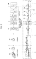
- a drive device 100 which raises and lowers the grate 16 includes a link mechanism 110 which movably supports the grate 16, a spring 120 which urges the grate 16 to the lowered position, a grate raising/lowering cam 130 which periodically raises and lowers the grate 16, a skip feed cam 140 which skip-feeds the sheet 10a, an oscillating cam 151 which is driven by an air cylinder 150, and a control device (control means) 160 which controls the skip feed cam 140 and the air cylinder 150.
- the grate 16 includes a table portion 16a which abuts on the lowermost sheet 10a and leg portions 16b which protrude downward from the table portion 16a. Total of four leg portions 16b are provided front, rear, right, and left.
- the table portion 16a is horizontally disposed, and the respective leg portions 16b vertically protrude downward.
- the lower portions of the respective leg portions 16b are connected to the link mechanism 110.
- only front leg portions 16b among right and left leg portions 16b are shown in Fig. 1 .
- the link mechanism 110 includes a pair of first links 111A and 111B in which one end is connected to the leg portion 16b of the grate 16 via a pin 111a and a position of an intermediate portion is rotatably fixed via a pin 111b, a second link 112 which connects the other end of the pair of first links 111A and 111B extending downward to each other via the pins 112a and 112a, a third link 113 in which one end is connected to an extension portion 111c on one end side of the first one link 111A via a pin 113a, and a fourth link 114 in which one end is connected to the other end of the third link 113 via a pin 114a and a position of an intermediate portion is rotatably fixed via a pin 114b.
- first link 111A and 111B are disposed to be approximately horizontal and can effectively raise and lower the leg portions 16b.
- the second link 112 is horizontally or approximately horizontally disposed, and the grate 16, the first links 111A and 111B, and the second link 112 configure a parallel link.
- the third link 113 is approximately vertically disposed and can effectively transmit a force for raising and lowering the leg portions 16b.
- the fourth link 114 is approximately horizontally disposed, which is an oscillating link in which the position of the intermediate portion is rotatably fixed via the pin 114b, and the fourth link 114 can effectively transmit a force for raising and lowering the leg portions 16b via the third link 113.
- link mechanism 110 only one set of link mechanism 110 is provided, right and left leg portions 16b are connected to the respective pins 111a, and the respective leg portions 16b disposed right and left in each of forward-rearward are simultaneously raised and lowered by the one set of link mechanism 110.
- the link mechanism 110 may be provided in each of the right and left leg portions 16b, and the link mechanisms 110 may be operated in synchronization with each other.
- the spring 120 engages with the other end side of the fourth link 114 of the link mechanism 110, and applies an urging force in the counterclockwise direction in Fig. 1 to the fourth link 114. If the fourth link 114 receives the urging force in the counterclockwise direction in Fig. 1 , one end side of the fourth link 114 is urged downward, and the first link 111A connected to the fourth link 114 via the third link 113 receives an urging force in the clockwise direction in Fig. 1 . If this urging force is exerted, the leg portion 16b connected to the first link 111A and the leg portion 16b which is connected to the first link 111B interlocked with the first link 111A via the second link 112 are urged downward. Accordingly, if other forces are not operated, the grate 16 is lowered toward the lowered position by the spring 120.
- the grate raising/lowering cam 130 is a rotary cam and includes a cam surface 131 which can abut one side (lower surface side) of one end side of the fourth link 114 of the link mechanism 110 from below. If the skip feed cam 140 and the oscillating cam 151 do not abut on the fourth link 114, the cam surface 131 always abuts on the fourth link 114 against the urging force of the spring 120.
- the grate 16 is raised at a rotation phase at which the cam lobe 132 abuts on the fourth link 114, and grate 16 is lowered at a rotation phase at which a portion except for the cam lobe 132 abuts on the fourth link 114.
- the grate raising/lowering cam 130 is rotationally driven by a drive mechanism (not shown) so as to be interlocked with a main system (a main drive system of the sheet processing section) of the carton-forming machine, and as described above, the grate raising/lowering cam 130 raises and lowers the grate 16 between the raised position and the lowered position while being rotated at a predetermined timing in synchronization with the operation and stopping of the wheel 15.
- the skip feed cam 140 is a rotary cam, includes a cam surface 141 which can abut on the other side (here, upper surface side) of the other end side of the fourth link 114 of the link mechanism 110, and is rotationally driven by an electric motor 143 separately from the drive system of the grate raising/lowering cam 130.
- the grate 16 is raised at a rotation phase at which the cam lobe 142 abuts on the fourth link 114, and grate 16 is lowered at a rotation phase or the lifting of the grate 16 by the grate raising/lowering cam 130 or the oscillating cam 151 is not hindered at which a portion except for the cam lobe 142 abuts on the fourth link 114.
- operation of the skip feed cam 140 is controlled by the control device 160.
- operation modes of the paper supply device 1M includes a normal mode and a skip feed mode, the normal mode is selected in a case where a relatively short corrugated fiberboard equal to or less than a predetermined length is processed in the transport direction, and the skip feed mode is selected in a case where a relatively long corrugated fiberboard equal to or less than a predetermined length is processed in the transport direction.
- This selection is performed by the control device 160 from input order information or an operator.
- the selection by an operator is performed by inputting selection information to the control device 160.
- the control device 160 controls the operation of the skip feed cam 140 through the electric motor 143, stops the skip feed cam 140 in a state where the cam surface 141 is separated from the fourth link 114 of the link mechanism 110 at the time of the normal mode, and operates the skip feed cam 140 at the time of the skip feed mode.
- an operation timing when the skip feed cam 140 is operated will be described later.
- the air cylinder 150 includes a fixed cylinder body 150a and a piston rod (hereinafter, simply referred to as a rod) 150b which is connected to a piston (not shown) moving according to an air pressure of an air chamber (not shown) inside the cylinder body 150a and in which a protrusion stroke from the cylinder body 150a is changed, and the air cylinder 150 can operate the grate 16 such that the grate 16 is positioned the raised position regardless of the respective phases of the grate raising/lowering cam 130 and the skip feed cam 140.
- a rod hereinafter, simply referred to as a rod
- the distal end portion of the rod 150b is connected to the oscillating cam (movable portion) 151 via an extension member 156 and an auxiliary link mechanism 155, and the phase of the oscillating cam 151 is changed according to extension and contraction of the air cylinder 150, that is, the change of the protrusion stroke of the rod 150b.
- the intermediate portion of the oscillating cam 151 is rotatably supported by a pin 154, a cam surface 152 which can abut on the other side (here, upper surface side) of the outer end side of the fourth link 114 of the link mechanism 110 is formed on one side of the oscillating cam 151, and a lever portion 153 extends from the other side of the oscillating cam 151.
- a protruding cam lobe 152a is formed on the cam surface 152, and if the cam lobe 152a abuts on the upper surface on the other end side of the fourth link 114, the grate 16 is raised.
- the auxiliary link mechanism 155 includes an auxiliary link 157 which is pin-connected to the extension member 156 connected to the distal end portion of the rod 150b and the lever portion 153 of the oscillating cam 151 by pins 157a and 157b, and if the air cylinder 150 is contracted (if the protrusion stroke of the rod 150b decreases), as shown by a solid line in Fig. 1 , the cam lobe 152a abuts on the upper surface of the other end side of the fourth link 114 to position the grate 16 at the raised position.
- the cam surface 152 is separated from the upper surface of the other end side of the fourth link 114, and the operation of the grate raising/lowering cam 130 or the skip feed cam 140 is not hindered.
- the air cylinder 150 is contracted only when the device (carton-forming machine) is stopped (including the time of emergency stop), reliably maintains the grate 16 at the raised position, extends when the device (carton-forming machine) is operated, and is used so as not to hinder the operations of other cams 130 and 140.
- the air cylinder 150 is configured so as to increase the protrusion stroke of the rod 150b by air supply and decrease the protrusion stroke of the rod 150b by air discharging. Accordingly, since air is discharged when the device is stopped, the protrusion stroke of the rod 150b decreases, and as shown by a solid line in Fig. 1 , the cam lobe 152a of the oscillating cam 151 abuts on the upper surface of the other end side of the fourth link 114, and the grate 16 is reliably maintained at the raised position.
- the operation timing of the skip feed cam 140 is described.
- the skip feed cam 140 is rotationally driven by the electric motor 143 separately from the drive system of the grate raising/lowering cam 130.
- the operation of the electric motor 143 (specifically, a motor driver 144 which drives the electric motor 143) is controlled by the control device 160.
- phase sensor (first phase detection means) 171 which detects the phase of the grate raising/lowering cam 130 and a phase sensor (second phase detection means) 172 which detects the phase of the skip feed cam 140 are installed, and the control device 160 receives detection information of the phase sensors 171 and 172 and controls the phase of the electric motor 143 such that the skip feed cam 140 rotates at a predetermined phase as shown in Fig. 3 with respect to the phase of the grate raising/lowering cam 130.
- a horizontal axis indicates the rotation phases of the respective cams 130 and 140
- a vertical axis indicates a raising/lowering level of the grate 16 with respect to the rotation phases of the respective cams 130 and 140.
- a broken line indicates characteristics of the grate raising/lowering cam 130
- a two-dot chain line indicates characteristics of the skip feed cam 140
- a solid line indicates characteristics of a combination of the grate raising/lowering cam 130 and the skip feed cam 140.
- the skip feed cam 140 raises the grate 16 once with respect to two rotations (720°) of the main drive system while the grate raising/lowering cam 130 raises the grate 16 once (here, the rotation phase is from the vicinity of 180° to immediately before the vicinity of 360°) with respect to one rotation (360°) of the main drive system, as shown by the broken line in Fig. 3 .
- a start timing when the skip feed cam 140 raises the grate 16 is set while the grate raising/lowering cam 130 raises the grate 16 at a period, and an end timing when the skip feed cam 140 raises the grate 16 is set while the grate raising/lowering cam 130 raises the grate 16 at the next period.
- the grate raising/lowering cam 130 and the skip feed cam 140 are in states of lowering the grate 16, and the grate 16 is positioned at the lowered position such that the upper surface of the grate 16 is positioned at a height L2 which is lower than a height L1 of the upper edge of the wheel 15.
- the grate raising/lowering cam 130 is in a state of raising the grate 16, and the grate 16 is raised to the raised position at which the upper surface of the grate 16 reaches a height L3 which is higher than the height L1 of the upper edge of the wheel 15.
- the grate raising/lowering cam 130 is still in the state of positioning the grate 16 at the raised position (height L3), and at this time, as shown in Fig. 4B , the skip feed cam 140 becomes a state of positioning the grates 16 at the raised position.
- the timing of the raising operation of the skip feed cam 140 may be set to any timing as long as it is within a period in which the grate raising/lowering cam 130 is in the state of positioning the grate 16 at the raised position.
- the rotation phase of the main drive system reaches the vicinity of 360°, and the grate raising/lowering cam 130 is in the state of positioning the grate 16 at the lowered position.
- the skip feed cam 140 is still in the state of maintaining the grate 16 at the raised position (height L3), the grate 16 is maintained at the raised position.
- the rotation phase of the main drive system proceeds to the vicinity of 540°, the grate raising/lowering cam 130 becomes a state of positioning the grate 16 at the raised position.
- the skip feed cam 140 becomes a state of lowering the grate 16.
- the grate raising/lowering cam 130 is still in the state of raising the grate 16
- the grate 16 is maintained at the raised position (height L3).
- the grate raising/lowering cam 130 becomes the state of lowering the grate 16, and the grate 16 is lowered.
- the timing of the lowering operation of the skip feed cam 140 may be any timing as long as it is within a period in which the grate raising/lowering cam 130 is in the state of positioning the grate 16 at the raised position.
- an emergency stop switch (emergency stop command means) 173 is installed, which issues an emergency stop command to feeding of sheet to the downstream side of the carton-forming machine by a paper supply device 10M, and the emergency stop command is performed by a switch operation by an operator. If the emergency stop switch 173 is operated, the control device 160 controls the air cylinder 150 to maintain the grate 16 at the raised position. That is, the control device 160 controls a valve unit 158 of the air cylinder 150 such that the protrusion stroke of the rod 150b is decreased by air discharging.
- the sheet feeder according to the embodiment of the present invention and the carton-forming machine including the same are configured as described above, the plurality of wheels 15 are repeatedly operated and stopped, and the grate 16 is raised and lowered in cooperation with the operations of the respective wheels 15.
- the skip feed cam 140 does not influence the movement of the grate 16.
- the respective wheels 15 are operated (rotated)
- the grate raising/lowering cam 130 positions the grate 16 at the lowered position and the lowermost sheet 10a abuts on the respective wheels 15, the respective wheels 15 feed the lowermost sheet 10a to the downstream side of the carton-forming machine.
- the control device 160 operates the skip feed cam 140 and maintains the grate 16 at the raised position to skip-feed the lowermost sheet 10a at the timing becomes the phase in which the grate raising/lowering cam 130 does not position the grate 16 at the raised position. Since the skip feed cam 140 is controlled in this way, it is possible to realize the normal sheet supply (normal mode) and the skip-feed supply (skip feed mode) in which the sheet supply is appropriately skipped with respect to the normal sheet supply.
- control device 160 controls the rotation phase of the skip feed cam 140 corresponding to the phase of the grate raising/lowering cam 130 based on the phase of the grate raising/lowering cam 130 and the phase of the skip feed cam 140 detected by the phase sensors 171 and 172, it is possible to appropriately perform the skip-feed to pause the sheet supply performed by the grate raising/lowering cam 130 once.
- the control device 160 controls the air cylinder 150 so as to maintain the grate 16 at the raised position. Specifically, the control device 160 controls the valve unit 158 of the air cylinder 150 such that the protrusion stroke of the rod 150b is decreased by air discharging. In this way, since the emergency stop performed by the air cylinder 150 is reliably performed by the air discharging, it is possible to obtain high reliability with respect to the emergency stop.
- the present invention is not limited to the above-described embodiment and may be variously modified within a scope which does not depart from the gist of the present invention.
- the air cylinder 150 and the oscillating cam 151 for emergency stop are provided, the emergency stop is performed by air discharging, and the high reliability with respect to the emergency stop is secured.
- a normal time that is, a state which does not influence the operation of the grate 16 may be realized by the air discharging, and the emergency stop may be performed by air supply. It is considered that the reliability with respect to the emergency stop in the case where the air supply is performed at the time of the emergency stop is higher than that of the case where the air discharging is performed.
- the air discharging state since the air discharging state is maintained, it is possible to save pump actuation energy of an air pressure generation.
- the air cylinder instead of the air cylinder, other fluid pressure cylinders such as a hydraulic cylinder may be applied.
- the cylinder is not limited to the air cylinder, and it is possible to easily secure a supporting force which maintains the grate 16 at the raised position and easily secure reliability with respect to the emergency stop as long as the fluid pressure cylinder is used.
- the oscillating cam 151 Since the oscillating cam 151 is connected to the air cylinder 150 via the auxiliary link 155, the oscillating cam 151 is oscillated by the extension and contraction stroke of the air cylinder 150 to operate the link mechanism 110, and the state where the grate 16 is raised and maintained, it is possible to smoothly apply the operation force raising the grate 16 to the link mechanism 110.
- the rod 150b or the like of the air cylinder 150 may directly abut on the link mechanism 110 to maintain the state where the grate 16 is raised.
- the skip feed cam 140 may be used for the emergency stop. Since the skip feed cam 140 is driven by the electric motor 143 independent from the main drive system, the skip feed cam 140 is fixed to the phase where the grate 16 is maintained at the raised position with respect to trouble or the like of the main drive system, and it is possible to emergency-stop the sheet supply.
- the raising and lowering operation of the grate 16 by the skip feed cam 140 is performed only once while the raising and lowering operation of the grate 16 by the grate raising/lowering cam 130 is performed twice.
- various configurations with respect to the skip-feed are considered such as a configuration in which the raising and lowering operation of the grate 16 by the skip feed cam 140 is performed only once while the raising and lowering operation of the grate 16 by the grate raising/lowering cam 130 is performed three times. It is considered that a plurality of skip feed cams 140 are provided and the skip-feed is selectively performed from a plurality of variations.
- the skip feed cam 140 may be used instead of the grate raising/lowering cam 130.
- each of the grate raising/lowering cam 130 and the skip feed cam 140 has only one cam lobe, but may include a plurality of cam lobes.
- each of the grate raising/lowering cam 130 and the skip feed cam 140 has only one cam lobe, but may include a plurality of cam lobes.
- the raising and lowering operation of the grate 16 by the skip feed cam 140 can be performed only once while the raising and lowering operation of the grate 16 by the grate raising/lowering cam 130 is performed twice.
- each of the spring 120, the grate raising/lowering cam 130, the skip feed cam 140, and the oscillating cam 151 of the air cylinder 150 may abut on any link of the link mechanism 110 so as to apply a desired movement to the link, or may abut on a separate link.
- the carton-forming machine is exemplified as the sheet processing device
- the corrugated fiberboard supply device is exemplified as the sheet feeder.
- the sheet feeder of the present invention is not limited to the carton-forming machine, and can be widely applied to a sheet processing device which processes a plate-shaped sheet such as a paper converting machine which processes a paperboard.
Landscapes
- Engineering & Computer Science (AREA)
- Mechanical Engineering (AREA)
- Sheets, Magazines, And Separation Thereof (AREA)
- Preliminary Treatment Of Fibers (AREA)
- Making Paper Articles (AREA)
Applications Claiming Priority (2)
| Application Number | Priority Date | Filing Date | Title |
|---|---|---|---|
| JP2014233771A JP6270050B2 (ja) | 2014-11-18 | 2014-11-18 | シート供給装置 |
| PCT/JP2015/076990 WO2016080072A1 (ja) | 2014-11-18 | 2015-09-24 | シート供給装置 |
Publications (3)
| Publication Number | Publication Date |
|---|---|
| EP3208219A1 true EP3208219A1 (de) | 2017-08-23 |
| EP3208219A4 EP3208219A4 (de) | 2017-12-13 |
| EP3208219B1 EP3208219B1 (de) | 2019-05-01 |
Family
ID=56013632
Family Applications (1)
| Application Number | Title | Priority Date | Filing Date |
|---|---|---|---|
| EP15860264.9A Active EP3208219B1 (de) | 2014-11-18 | 2015-09-24 | Blattzuführvorrichtung |
Country Status (6)
| Country | Link |
|---|---|
| US (1) | US10343861B2 (de) |
| EP (1) | EP3208219B1 (de) |
| JP (1) | JP6270050B2 (de) |
| KR (1) | KR101941799B1 (de) |
| CN (1) | CN107108137B (de) |
| WO (1) | WO2016080072A1 (de) |
Cited By (1)
| Publication number | Priority date | Publication date | Assignee | Title |
|---|---|---|---|---|
| CN112469648A (zh) * | 2018-02-26 | 2021-03-09 | 太阳自动化股份有限公司 | 无进给辊的瓦楞纸板或卡板片材进给器改装装置和方法 |
Families Citing this family (17)
| Publication number | Priority date | Publication date | Assignee | Title |
|---|---|---|---|---|
| CN106276338B (zh) * | 2016-08-23 | 2017-12-05 | 广东东方精工科技股份有限公司 | 一种同时下降分时上升抬板的送纸方法 |
| JP6872930B2 (ja) * | 2017-02-24 | 2021-05-19 | 三菱重工機械システム株式会社 | シート供給装置及び製函機 |
| CN107472942B (zh) * | 2017-08-31 | 2023-06-20 | 广东东方精工科技股份有限公司 | 一种送纸装置 |
| CN108529270B (zh) * | 2018-03-23 | 2019-09-03 | 广东东方精工科技股份有限公司 | 一种自适应启动点的送纸方法 |
| CN108861691B (zh) * | 2018-03-23 | 2020-06-30 | 佛山赢联数码印刷设备有限公司 | 一种数字印刷机送纸机构的控制方法 |
| CN108749130A (zh) * | 2018-06-28 | 2018-11-06 | 东台市天时利包装有限公司 | 一种用于纸箱的纸板印刷的输送设备 |
| CN109850252B (zh) * | 2018-12-25 | 2020-09-15 | 四川汇利实业有限公司 | 一种用于间歇式输送纸板机构的操作方法 |
| CN109850253B (zh) * | 2018-12-25 | 2020-12-01 | 四川汇利实业有限公司 | 一种间歇式药品包装箱纸板输送机构 |
| CN110497648A (zh) * | 2019-08-16 | 2019-11-26 | 吉文献 | 基于凸轮复位原理的纸箱前处理纸板送料装置 |
| CN110561824A (zh) * | 2019-09-15 | 2019-12-13 | 安徽佰特包装制品有限公司 | 一种瓦楞纸箱生产线用前缘送纸机构 |
| JP7433021B2 (ja) * | 2019-11-08 | 2024-02-19 | 三菱重工機械システム株式会社 | 給紙装置および製函機 |
| JP7565581B2 (ja) | 2020-09-25 | 2024-10-11 | 株式会社Isowa | 段ボールシート製函機 |
| CN112340490A (zh) * | 2020-11-03 | 2021-02-09 | 徐州亮华包装制品有限公司 | 一种包装纸箱的连续自动取纸装置及其工作方法 |
| CN112623805B (zh) * | 2020-11-24 | 2024-04-05 | 杨恒鑫 | 一种用于彩色打印的送纸机构 |
| CN112722910A (zh) * | 2020-12-30 | 2021-04-30 | 北京宏林中设科技有限公司 | 一种印刷机自动放纸机构 |
| JP2022117332A (ja) * | 2021-01-29 | 2022-08-10 | ブラザー工業株式会社 | 分離装置及び分離方法 |
| CN115027804B (zh) * | 2021-03-05 | 2023-12-22 | 邬啸峰 | 一种纸质资料发放装置 |
Family Cites Families (19)
| Publication number | Priority date | Publication date | Assignee | Title |
|---|---|---|---|---|
| JPS54115870A (en) * | 1978-02-27 | 1979-09-08 | Masaharu Matsuo | Belt paper feeder |
| US4828244A (en) * | 1980-04-28 | 1989-05-09 | Wm. C. Staley Machinery Corporation | Intermittently protruding feeder for paperboard blanks |
| DE3572957D1 (en) * | 1984-11-23 | 1989-10-19 | Prime Technology Inc | Improvements in or relating to apparatus and methods for feeding articles such as sheets or boards |
| US4867433A (en) | 1988-02-19 | 1989-09-19 | The Ward Machinery Company | Dual feeding of sheets of processing machinery |
| JP2508544B2 (ja) | 1988-10-24 | 1996-06-19 | 横河電機株式会社 | グラフィックディスプレイ装置 |
| US5184811A (en) * | 1988-10-13 | 1993-02-09 | Sun Automation, Inc. | Method and apparatus for feeding sheets |
| US5531432A (en) * | 1988-10-13 | 1996-07-02 | Sardella; Louis M. | Method and apparatus for feeding sheets |
| US5048812A (en) * | 1988-11-03 | 1991-09-17 | Prime Technology | Sheet feeding apparatus |
| JPH085963Y2 (ja) | 1990-07-05 | 1996-02-21 | 三菱重工業株式会社 | 給紙装置 |
| US5074539A (en) * | 1990-09-11 | 1991-12-24 | Ward Holding Company, Inc. | Feeding sheets of corrugated paperboard |
| JP2508544Y2 (ja) * | 1991-02-19 | 1996-08-28 | 三菱重工業株式会社 | 板紙給紙装置 |
| JP2000191153A (ja) * | 1998-12-25 | 2000-07-11 | Ishikawa Seisakusho Ltd | 段ボ―ルシ―ト供給装置 |
| JP3871974B2 (ja) * | 2001-12-17 | 2007-01-24 | 株式会社名南製作所 | ベニヤ単板の接合方法及び接合装置 |
| US7635124B2 (en) * | 2005-12-28 | 2009-12-22 | Sun Automation, Inc. | Feeder with adjustable time cycle and method |
| JP2008230850A (ja) | 2007-02-23 | 2008-10-02 | Ishikawa Seisakusho Ltd | シート状ワークの送り出し装置及びシート状ワークの送り出し方法 |
| JP4976362B2 (ja) | 2007-10-26 | 2012-07-18 | 株式会社石川製作所 | シート状ワークの送り出し装置及びシート状ワークの送り出し方法 |
| JP6045023B2 (ja) | 2012-11-19 | 2016-12-14 | 株式会社Isowa | サクション機構を備えた給紙装置、および、その給紙制御方法 |
| US9701498B2 (en) * | 2015-01-09 | 2017-07-11 | Kabushiki Kaisha Isowa | Corrugated paperboard sheet feeding apparatus |
| US9522798B2 (en) * | 2015-04-30 | 2016-12-20 | Theodore Michael Baum | Corrugated paperboard box converting machine retrofit for eliminating edge crush test degradation |
-
2014
- 2014-11-18 JP JP2014233771A patent/JP6270050B2/ja active Active
-
2015
- 2015-09-24 KR KR1020177013148A patent/KR101941799B1/ko not_active Expired - Fee Related
- 2015-09-24 US US15/527,697 patent/US10343861B2/en active Active
- 2015-09-24 WO PCT/JP2015/076990 patent/WO2016080072A1/ja not_active Ceased
- 2015-09-24 CN CN201580062614.5A patent/CN107108137B/zh active Active
- 2015-09-24 EP EP15860264.9A patent/EP3208219B1/de active Active
Cited By (4)
| Publication number | Priority date | Publication date | Assignee | Title |
|---|---|---|---|---|
| CN112469648A (zh) * | 2018-02-26 | 2021-03-09 | 太阳自动化股份有限公司 | 无进给辊的瓦楞纸板或卡板片材进给器改装装置和方法 |
| EP3759039A4 (de) * | 2018-02-26 | 2022-04-06 | Sun Automation, Inc. | Vorrichtung und verfahren zur nachrüstung eines wellpappe- oder pappebogenzuführers ohne einzugswalze |
| CN112469648B (zh) * | 2018-02-26 | 2023-02-21 | 太阳自动化股份有限公司 | 无进给辊的瓦楞纸板或卡板片材进给器改装装置和方法 |
| US12503325B2 (en) | 2018-02-26 | 2025-12-23 | Sun Automation, Inc. | No-feed-roll corrugated board or paperboard sheet feeder retrofit apparatus and method |
Also Published As
| Publication number | Publication date |
|---|---|
| EP3208219B1 (de) | 2019-05-01 |
| US10343861B2 (en) | 2019-07-09 |
| JP2016098050A (ja) | 2016-05-30 |
| EP3208219A4 (de) | 2017-12-13 |
| KR101941799B1 (ko) | 2019-01-23 |
| CN107108137A (zh) | 2017-08-29 |
| US20190062085A1 (en) | 2019-02-28 |
| WO2016080072A1 (ja) | 2016-05-26 |
| KR20170067891A (ko) | 2017-06-16 |
| JP6270050B2 (ja) | 2018-01-31 |
| CN107108137B (zh) | 2018-11-16 |
Similar Documents
| Publication | Publication Date | Title |
|---|---|---|
| EP3208219B1 (de) | Blattzuführvorrichtung | |
| EP2818312B1 (de) | Blattfaltvorrichtung und kartonformungsvorrichtung | |
| US9522477B2 (en) | Corrugated paperboard box making machine | |
| US9327934B2 (en) | Sheet stacking apparatus and sheet stacking method | |
| JP6524503B2 (ja) | 段ボールシート給紙装置 | |
| US20140162862A1 (en) | Corrugated paperboard box making machine, and inter-sheet pacing device therefor | |
| CN115103748B (zh) | 用于印张分离的装置及方法 | |
| US11890829B2 (en) | Cardboard box dividing device and cardboard box production device | |
| JP2008030952A (ja) | 後縁制動装置 | |
| JP2019514812A (ja) | チェーン引張器、シートの形態の要素を処理するための機械、及びチェーンセットを引張する方法 | |
| WO2011027204A1 (en) | Creasing unit for processing web material blanks | |
| JP2011251816A (ja) | 筋付け装置、及び画像形成システム | |
| CN110203751B (zh) | 用于对根据顺序地印刷的印张进行继续加工的装置和方法 | |
| CN115916493B (zh) | 用于印张分离的装置及方法 | |
| JP6415993B2 (ja) | 段ボールシート給送装置 | |
| CN115605332B (zh) | 用于印张分离的装置及方法 | |
| CN114555497B (zh) | 具有至少一个单张纸摞放装置的单张纸加工机和用于单张纸摞放的方法 | |
| CN103057173B (zh) | 用于运行压印装置的方法 | |
| JP2021160337A (ja) | 段ボールシートの製函機 | |
| JP7433021B2 (ja) | 給紙装置および製函機 | |
| JP5307615B2 (ja) | 連続用紙の丁合装置 | |
| JP5231087B2 (ja) | 羽根車装置 | |
| JP5081723B2 (ja) | 羽根車装置 | |
| KR20160132621A (ko) | 책자형 인쇄물의 표지 인쇄기 | |
| KR20130084755A (ko) | 톰슨 절단기를 위한 자동급지장치 |
Legal Events
| Date | Code | Title | Description |
|---|---|---|---|
| STAA | Information on the status of an ep patent application or granted ep patent |
Free format text: STATUS: THE INTERNATIONAL PUBLICATION HAS BEEN MADE |
|
| PUAI | Public reference made under article 153(3) epc to a published international application that has entered the european phase |
Free format text: ORIGINAL CODE: 0009012 |
|
| STAA | Information on the status of an ep patent application or granted ep patent |
Free format text: STATUS: REQUEST FOR EXAMINATION WAS MADE |
|
| 17P | Request for examination filed |
Effective date: 20170518 |
|
| AK | Designated contracting states |
Kind code of ref document: A1 Designated state(s): AL AT BE BG CH CY CZ DE DK EE ES FI FR GB GR HR HU IE IS IT LI LT LU LV MC MK MT NL NO PL PT RO RS SE SI SK SM TR |
|
| AX | Request for extension of the european patent |
Extension state: BA ME |
|
| A4 | Supplementary search report drawn up and despatched |
Effective date: 20171110 |
|
| RIC1 | Information provided on ipc code assigned before grant |
Ipc: B65H 3/34 20060101ALI20171106BHEP Ipc: B65H 3/06 20060101AFI20171106BHEP Ipc: B65H 7/02 20060101ALI20171106BHEP Ipc: B65H 7/18 20060101ALI20171106BHEP |
|
| DAV | Request for validation of the european patent (deleted) | ||
| DAX | Request for extension of the european patent (deleted) | ||
| RAP1 | Party data changed (applicant data changed or rights of an application transferred) |
Owner name: MITSUBISHI HEAVY INDUSTRIES MACHINERY SYSTEMS, LTD |
|
| GRAP | Despatch of communication of intention to grant a patent |
Free format text: ORIGINAL CODE: EPIDOSNIGR1 |
|
| STAA | Information on the status of an ep patent application or granted ep patent |
Free format text: STATUS: GRANT OF PATENT IS INTENDED |
|
| RIC1 | Information provided on ipc code assigned before grant |
Ipc: B65H 3/06 20060101AFI20181121BHEP Ipc: B65H 7/02 20060101ALI20181121BHEP Ipc: B65H 7/18 20060101ALI20181121BHEP Ipc: B65H 3/34 20060101ALI20181121BHEP |
|
| INTG | Intention to grant announced |
Effective date: 20181221 |
|
| GRAS | Grant fee paid |
Free format text: ORIGINAL CODE: EPIDOSNIGR3 |
|
| GRAA | (expected) grant |
Free format text: ORIGINAL CODE: 0009210 |
|
| STAA | Information on the status of an ep patent application or granted ep patent |
Free format text: STATUS: THE PATENT HAS BEEN GRANTED |
|
| AK | Designated contracting states |
Kind code of ref document: B1 Designated state(s): AL AT BE BG CH CY CZ DE DK EE ES FI FR GB GR HR HU IE IS IT LI LT LU LV MC MK MT NL NO PL PT RO RS SE SI SK SM TR |
|
| REG | Reference to a national code |
Ref country code: GB Ref legal event code: FG4D |
|
| REG | Reference to a national code |
Ref country code: CH Ref legal event code: EP Ref country code: AT Ref legal event code: REF Ref document number: 1126650 Country of ref document: AT Kind code of ref document: T Effective date: 20190515 |
|
| REG | Reference to a national code |
Ref country code: DE Ref legal event code: R096 Ref document number: 602015029566 Country of ref document: DE |
|
| REG | Reference to a national code |
Ref country code: IE Ref legal event code: FG4D |
|
| REG | Reference to a national code |
Ref country code: NL Ref legal event code: MP Effective date: 20190501 |
|
| REG | Reference to a national code |
Ref country code: LT Ref legal event code: MG4D |
|
| PG25 | Lapsed in a contracting state [announced via postgrant information from national office to epo] |
Ref country code: NL Free format text: LAPSE BECAUSE OF FAILURE TO SUBMIT A TRANSLATION OF THE DESCRIPTION OR TO PAY THE FEE WITHIN THE PRESCRIBED TIME-LIMIT Effective date: 20190501 Ref country code: SE Free format text: LAPSE BECAUSE OF FAILURE TO SUBMIT A TRANSLATION OF THE DESCRIPTION OR TO PAY THE FEE WITHIN THE PRESCRIBED TIME-LIMIT Effective date: 20190501 Ref country code: HR Free format text: LAPSE BECAUSE OF FAILURE TO SUBMIT A TRANSLATION OF THE DESCRIPTION OR TO PAY THE FEE WITHIN THE PRESCRIBED TIME-LIMIT Effective date: 20190501 Ref country code: NO Free format text: LAPSE BECAUSE OF FAILURE TO SUBMIT A TRANSLATION OF THE DESCRIPTION OR TO PAY THE FEE WITHIN THE PRESCRIBED TIME-LIMIT Effective date: 20190801 Ref country code: AL Free format text: LAPSE BECAUSE OF FAILURE TO SUBMIT A TRANSLATION OF THE DESCRIPTION OR TO PAY THE FEE WITHIN THE PRESCRIBED TIME-LIMIT Effective date: 20190501 Ref country code: PT Free format text: LAPSE BECAUSE OF FAILURE TO SUBMIT A TRANSLATION OF THE DESCRIPTION OR TO PAY THE FEE WITHIN THE PRESCRIBED TIME-LIMIT Effective date: 20190901 Ref country code: FI Free format text: LAPSE BECAUSE OF FAILURE TO SUBMIT A TRANSLATION OF THE DESCRIPTION OR TO PAY THE FEE WITHIN THE PRESCRIBED TIME-LIMIT Effective date: 20190501 Ref country code: LT Free format text: LAPSE BECAUSE OF FAILURE TO SUBMIT A TRANSLATION OF THE DESCRIPTION OR TO PAY THE FEE WITHIN THE PRESCRIBED TIME-LIMIT Effective date: 20190501 |
|
| PG25 | Lapsed in a contracting state [announced via postgrant information from national office to epo] |
Ref country code: BG Free format text: LAPSE BECAUSE OF FAILURE TO SUBMIT A TRANSLATION OF THE DESCRIPTION OR TO PAY THE FEE WITHIN THE PRESCRIBED TIME-LIMIT Effective date: 20190801 Ref country code: RS Free format text: LAPSE BECAUSE OF FAILURE TO SUBMIT A TRANSLATION OF THE DESCRIPTION OR TO PAY THE FEE WITHIN THE PRESCRIBED TIME-LIMIT Effective date: 20190501 Ref country code: LV Free format text: LAPSE BECAUSE OF FAILURE TO SUBMIT A TRANSLATION OF THE DESCRIPTION OR TO PAY THE FEE WITHIN THE PRESCRIBED TIME-LIMIT Effective date: 20190501 Ref country code: GR Free format text: LAPSE BECAUSE OF FAILURE TO SUBMIT A TRANSLATION OF THE DESCRIPTION OR TO PAY THE FEE WITHIN THE PRESCRIBED TIME-LIMIT Effective date: 20190802 |
|
| REG | Reference to a national code |
Ref country code: AT Ref legal event code: MK05 Ref document number: 1126650 Country of ref document: AT Kind code of ref document: T Effective date: 20190501 |
|
| PG25 | Lapsed in a contracting state [announced via postgrant information from national office to epo] |
Ref country code: IS Free format text: LAPSE BECAUSE OF FAILURE TO SUBMIT A TRANSLATION OF THE DESCRIPTION OR TO PAY THE FEE WITHIN THE PRESCRIBED TIME-LIMIT Effective date: 20190901 |
|
| PG25 | Lapsed in a contracting state [announced via postgrant information from national office to epo] |
Ref country code: EE Free format text: LAPSE BECAUSE OF FAILURE TO SUBMIT A TRANSLATION OF THE DESCRIPTION OR TO PAY THE FEE WITHIN THE PRESCRIBED TIME-LIMIT Effective date: 20190501 Ref country code: AT Free format text: LAPSE BECAUSE OF FAILURE TO SUBMIT A TRANSLATION OF THE DESCRIPTION OR TO PAY THE FEE WITHIN THE PRESCRIBED TIME-LIMIT Effective date: 20190501 Ref country code: DK Free format text: LAPSE BECAUSE OF FAILURE TO SUBMIT A TRANSLATION OF THE DESCRIPTION OR TO PAY THE FEE WITHIN THE PRESCRIBED TIME-LIMIT Effective date: 20190501 Ref country code: CZ Free format text: LAPSE BECAUSE OF FAILURE TO SUBMIT A TRANSLATION OF THE DESCRIPTION OR TO PAY THE FEE WITHIN THE PRESCRIBED TIME-LIMIT Effective date: 20190501 Ref country code: RO Free format text: LAPSE BECAUSE OF FAILURE TO SUBMIT A TRANSLATION OF THE DESCRIPTION OR TO PAY THE FEE WITHIN THE PRESCRIBED TIME-LIMIT Effective date: 20190501 Ref country code: SK Free format text: LAPSE BECAUSE OF FAILURE TO SUBMIT A TRANSLATION OF THE DESCRIPTION OR TO PAY THE FEE WITHIN THE PRESCRIBED TIME-LIMIT Effective date: 20190501 |
|
| REG | Reference to a national code |
Ref country code: DE Ref legal event code: R097 Ref document number: 602015029566 Country of ref document: DE |
|
| PG25 | Lapsed in a contracting state [announced via postgrant information from national office to epo] |
Ref country code: SM Free format text: LAPSE BECAUSE OF FAILURE TO SUBMIT A TRANSLATION OF THE DESCRIPTION OR TO PAY THE FEE WITHIN THE PRESCRIBED TIME-LIMIT Effective date: 20190501 Ref country code: IT Free format text: LAPSE BECAUSE OF FAILURE TO SUBMIT A TRANSLATION OF THE DESCRIPTION OR TO PAY THE FEE WITHIN THE PRESCRIBED TIME-LIMIT Effective date: 20190501 |
|
| PLBE | No opposition filed within time limit |
Free format text: ORIGINAL CODE: 0009261 |
|
| STAA | Information on the status of an ep patent application or granted ep patent |
Free format text: STATUS: NO OPPOSITION FILED WITHIN TIME LIMIT |
|
| PG25 | Lapsed in a contracting state [announced via postgrant information from national office to epo] |
Ref country code: TR Free format text: LAPSE BECAUSE OF FAILURE TO SUBMIT A TRANSLATION OF THE DESCRIPTION OR TO PAY THE FEE WITHIN THE PRESCRIBED TIME-LIMIT Effective date: 20190501 |
|
| REG | Reference to a national code |
Ref country code: DE Ref legal event code: R119 Ref document number: 602015029566 Country of ref document: DE |
|
| 26N | No opposition filed |
Effective date: 20200204 |
|
| PG25 | Lapsed in a contracting state [announced via postgrant information from national office to epo] |
Ref country code: PL Free format text: LAPSE BECAUSE OF FAILURE TO SUBMIT A TRANSLATION OF THE DESCRIPTION OR TO PAY THE FEE WITHIN THE PRESCRIBED TIME-LIMIT Effective date: 20190501 |
|
| PG25 | Lapsed in a contracting state [announced via postgrant information from national office to epo] |
Ref country code: SI Free format text: LAPSE BECAUSE OF FAILURE TO SUBMIT A TRANSLATION OF THE DESCRIPTION OR TO PAY THE FEE WITHIN THE PRESCRIBED TIME-LIMIT Effective date: 20190501 Ref country code: MC Free format text: LAPSE BECAUSE OF FAILURE TO SUBMIT A TRANSLATION OF THE DESCRIPTION OR TO PAY THE FEE WITHIN THE PRESCRIBED TIME-LIMIT Effective date: 20190501 |
|
| REG | Reference to a national code |
Ref country code: CH Ref legal event code: PL |
|
| PG25 | Lapsed in a contracting state [announced via postgrant information from national office to epo] |
Ref country code: LI Free format text: LAPSE BECAUSE OF NON-PAYMENT OF DUE FEES Effective date: 20190930 Ref country code: IE Free format text: LAPSE BECAUSE OF NON-PAYMENT OF DUE FEES Effective date: 20190924 Ref country code: DE Free format text: LAPSE BECAUSE OF NON-PAYMENT OF DUE FEES Effective date: 20200401 Ref country code: CH Free format text: LAPSE BECAUSE OF NON-PAYMENT OF DUE FEES Effective date: 20190930 Ref country code: LU Free format text: LAPSE BECAUSE OF NON-PAYMENT OF DUE FEES Effective date: 20190924 |
|
| REG | Reference to a national code |
Ref country code: BE Ref legal event code: MM Effective date: 20190930 |
|
| PG25 | Lapsed in a contracting state [announced via postgrant information from national office to epo] |
Ref country code: BE Free format text: LAPSE BECAUSE OF NON-PAYMENT OF DUE FEES Effective date: 20190930 |
|
| GBPC | Gb: european patent ceased through non-payment of renewal fee |
Effective date: 20190924 |
|
| PG25 | Lapsed in a contracting state [announced via postgrant information from national office to epo] |
Ref country code: GB Free format text: LAPSE BECAUSE OF NON-PAYMENT OF DUE FEES Effective date: 20190924 Ref country code: ES Free format text: LAPSE BECAUSE OF FAILURE TO SUBMIT A TRANSLATION OF THE DESCRIPTION OR TO PAY THE FEE WITHIN THE PRESCRIBED TIME-LIMIT Effective date: 20190501 |
|
| PG25 | Lapsed in a contracting state [announced via postgrant information from national office to epo] |
Ref country code: CY Free format text: LAPSE BECAUSE OF FAILURE TO SUBMIT A TRANSLATION OF THE DESCRIPTION OR TO PAY THE FEE WITHIN THE PRESCRIBED TIME-LIMIT Effective date: 20190501 |
|
| PG25 | Lapsed in a contracting state [announced via postgrant information from national office to epo] |
Ref country code: HU Free format text: LAPSE BECAUSE OF FAILURE TO SUBMIT A TRANSLATION OF THE DESCRIPTION OR TO PAY THE FEE WITHIN THE PRESCRIBED TIME-LIMIT; INVALID AB INITIO Effective date: 20150924 Ref country code: MT Free format text: LAPSE BECAUSE OF FAILURE TO SUBMIT A TRANSLATION OF THE DESCRIPTION OR TO PAY THE FEE WITHIN THE PRESCRIBED TIME-LIMIT Effective date: 20190501 |
|
| PG25 | Lapsed in a contracting state [announced via postgrant information from national office to epo] |
Ref country code: MK Free format text: LAPSE BECAUSE OF FAILURE TO SUBMIT A TRANSLATION OF THE DESCRIPTION OR TO PAY THE FEE WITHIN THE PRESCRIBED TIME-LIMIT Effective date: 20190501 |
|
| PGFP | Annual fee paid to national office [announced via postgrant information from national office to epo] |
Ref country code: FR Payment date: 20250808 Year of fee payment: 11 |