EP3208454A1 - Kurbelwellen-dichtflansch - Google Patents
Kurbelwellen-dichtflansch Download PDFInfo
- Publication number
- EP3208454A1 EP3208454A1 EP16002339.6A EP16002339A EP3208454A1 EP 3208454 A1 EP3208454 A1 EP 3208454A1 EP 16002339 A EP16002339 A EP 16002339A EP 3208454 A1 EP3208454 A1 EP 3208454A1
- Authority
- EP
- European Patent Office
- Prior art keywords
- sealing flange
- sensor
- carrier
- flange according
- electronic assembly
- Prior art date
- Legal status (The legal status is an assumption and is not a legal conclusion. Google has not performed a legal analysis and makes no representation as to the accuracy of the status listed.)
- Granted
Links
Images

Classifications
-
- F—MECHANICAL ENGINEERING; LIGHTING; HEATING; WEAPONS; BLASTING
- F16—ENGINEERING ELEMENTS AND UNITS; GENERAL MEASURES FOR PRODUCING AND MAINTAINING EFFECTIVE FUNCTIONING OF MACHINES OR INSTALLATIONS; THERMAL INSULATION IN GENERAL
- F16J—PISTONS; CYLINDERS; SEALINGS
- F16J15/00—Sealings
- F16J15/16—Sealings between relatively-moving surfaces
- F16J15/32—Sealings between relatively-moving surfaces with elastic sealings, e.g. O-rings
- F16J15/3248—Sealings between relatively-moving surfaces with elastic sealings, e.g. O-rings provided with casings or supports
- F16J15/3252—Sealings between relatively-moving surfaces with elastic sealings, e.g. O-rings provided with casings or supports with rigid casings or supports
-
- F—MECHANICAL ENGINEERING; LIGHTING; HEATING; WEAPONS; BLASTING
- F16—ENGINEERING ELEMENTS AND UNITS; GENERAL MEASURES FOR PRODUCING AND MAINTAINING EFFECTIVE FUNCTIONING OF MACHINES OR INSTALLATIONS; THERMAL INSULATION IN GENERAL
- F16C—SHAFTS; FLEXIBLE SHAFTS; ELEMENTS OR CRANKSHAFT MECHANISMS; ROTARY BODIES OTHER THAN GEARING ELEMENTS; BEARINGS
- F16C35/00—Rigid support of bearing units; Housings, e.g. caps, covers
- F16C35/02—Rigid support of bearing units; Housings, e.g. caps, covers in the case of sliding-contact bearings
-
- F—MECHANICAL ENGINEERING; LIGHTING; HEATING; WEAPONS; BLASTING
- F02—COMBUSTION ENGINES; HOT-GAS OR COMBUSTION-PRODUCT ENGINE PLANTS
- F02F—CYLINDERS, PISTONS OR CASINGS, FOR COMBUSTION ENGINES; ARRANGEMENTS OF SEALINGS IN COMBUSTION ENGINES
- F02F7/00—Casings, e.g. crankcases
- F02F7/0043—Arrangements of mechanical drive elements
-
- F—MECHANICAL ENGINEERING; LIGHTING; HEATING; WEAPONS; BLASTING
- F02—COMBUSTION ENGINES; HOT-GAS OR COMBUSTION-PRODUCT ENGINE PLANTS
- F02P—IGNITION, OTHER THAN COMPRESSION IGNITION, FOR INTERNAL-COMBUSTION ENGINES; TESTING OF IGNITION TIMING IN COMPRESSION-IGNITION ENGINES
- F02P7/00—Arrangements of distributors, circuit-makers or -breakers, e.g. of distributor and circuit-breaker combinations or pick-up devices
- F02P7/06—Arrangements of distributors, circuit-makers or -breakers, e.g. of distributor and circuit-breaker combinations or pick-up devices of circuit-makers or -breakers, or pick-up devices adapted to sense particular points of the timing cycle
- F02P7/067—Electromagnetic pick-up devices, e.g. providing induced current in a coil
-
- F—MECHANICAL ENGINEERING; LIGHTING; HEATING; WEAPONS; BLASTING
- F02—COMBUSTION ENGINES; HOT-GAS OR COMBUSTION-PRODUCT ENGINE PLANTS
- F02P—IGNITION, OTHER THAN COMPRESSION IGNITION, FOR INTERNAL-COMBUSTION ENGINES; TESTING OF IGNITION TIMING IN COMPRESSION-IGNITION ENGINES
- F02P7/00—Arrangements of distributors, circuit-makers or -breakers, e.g. of distributor and circuit-breaker combinations or pick-up devices
- F02P7/06—Arrangements of distributors, circuit-makers or -breakers, e.g. of distributor and circuit-breaker combinations or pick-up devices of circuit-makers or -breakers, or pick-up devices adapted to sense particular points of the timing cycle
- F02P7/067—Electromagnetic pick-up devices, e.g. providing induced current in a coil
- F02P7/07—Hall-effect pick-up devices
-
- F—MECHANICAL ENGINEERING; LIGHTING; HEATING; WEAPONS; BLASTING
- F16—ENGINEERING ELEMENTS AND UNITS; GENERAL MEASURES FOR PRODUCING AND MAINTAINING EFFECTIVE FUNCTIONING OF MACHINES OR INSTALLATIONS; THERMAL INSULATION IN GENERAL
- F16C—SHAFTS; FLEXIBLE SHAFTS; ELEMENTS OR CRANKSHAFT MECHANISMS; ROTARY BODIES OTHER THAN GEARING ELEMENTS; BEARINGS
- F16C33/00—Parts of bearings; Special methods for making bearings or parts thereof
- F16C33/02—Parts of sliding-contact bearings
- F16C33/04—Brasses; Bushes; Linings
- F16C33/20—Sliding surface consisting mainly of plastics
- F16C33/201—Composition of the plastic
-
- F—MECHANICAL ENGINEERING; LIGHTING; HEATING; WEAPONS; BLASTING
- F16—ENGINEERING ELEMENTS AND UNITS; GENERAL MEASURES FOR PRODUCING AND MAINTAINING EFFECTIVE FUNCTIONING OF MACHINES OR INSTALLATIONS; THERMAL INSULATION IN GENERAL
- F16C—SHAFTS; FLEXIBLE SHAFTS; ELEMENTS OR CRANKSHAFT MECHANISMS; ROTARY BODIES OTHER THAN GEARING ELEMENTS; BEARINGS
- F16C33/00—Parts of bearings; Special methods for making bearings or parts thereof
- F16C33/72—Sealings
- F16C33/74—Sealings of sliding-contact bearings
-
- F—MECHANICAL ENGINEERING; LIGHTING; HEATING; WEAPONS; BLASTING
- F16—ENGINEERING ELEMENTS AND UNITS; GENERAL MEASURES FOR PRODUCING AND MAINTAINING EFFECTIVE FUNCTIONING OF MACHINES OR INSTALLATIONS; THERMAL INSULATION IN GENERAL
- F16C—SHAFTS; FLEXIBLE SHAFTS; ELEMENTS OR CRANKSHAFT MECHANISMS; ROTARY BODIES OTHER THAN GEARING ELEMENTS; BEARINGS
- F16C41/00—Other accessories, e.g. devices integrated in the bearing not relating to the bearing function as such
-
- F—MECHANICAL ENGINEERING; LIGHTING; HEATING; WEAPONS; BLASTING
- F16—ENGINEERING ELEMENTS AND UNITS; GENERAL MEASURES FOR PRODUCING AND MAINTAINING EFFECTIVE FUNCTIONING OF MACHINES OR INSTALLATIONS; THERMAL INSULATION IN GENERAL
- F16C—SHAFTS; FLEXIBLE SHAFTS; ELEMENTS OR CRANKSHAFT MECHANISMS; ROTARY BODIES OTHER THAN GEARING ELEMENTS; BEARINGS
- F16C41/00—Other accessories, e.g. devices integrated in the bearing not relating to the bearing function as such
- F16C41/002—Conductive elements, e.g. to prevent static electricity
-
- F—MECHANICAL ENGINEERING; LIGHTING; HEATING; WEAPONS; BLASTING
- F16—ENGINEERING ELEMENTS AND UNITS; GENERAL MEASURES FOR PRODUCING AND MAINTAINING EFFECTIVE FUNCTIONING OF MACHINES OR INSTALLATIONS; THERMAL INSULATION IN GENERAL
- F16C—SHAFTS; FLEXIBLE SHAFTS; ELEMENTS OR CRANKSHAFT MECHANISMS; ROTARY BODIES OTHER THAN GEARING ELEMENTS; BEARINGS
- F16C9/00—Bearings for crankshafts or connecting-rods; Attachment of connecting-rods
- F16C9/02—Crankshaft bearings
-
- F—MECHANICAL ENGINEERING; LIGHTING; HEATING; WEAPONS; BLASTING
- F16—ENGINEERING ELEMENTS AND UNITS; GENERAL MEASURES FOR PRODUCING AND MAINTAINING EFFECTIVE FUNCTIONING OF MACHINES OR INSTALLATIONS; THERMAL INSULATION IN GENERAL
- F16J—PISTONS; CYLINDERS; SEALINGS
- F16J15/00—Sealings
- F16J15/16—Sealings between relatively-moving surfaces
- F16J15/32—Sealings between relatively-moving surfaces with elastic sealings, e.g. O-rings
- F16J15/3204—Sealings between relatively-moving surfaces with elastic sealings, e.g. O-rings with at least one lip
-
- F—MECHANICAL ENGINEERING; LIGHTING; HEATING; WEAPONS; BLASTING
- F16—ENGINEERING ELEMENTS AND UNITS; GENERAL MEASURES FOR PRODUCING AND MAINTAINING EFFECTIVE FUNCTIONING OF MACHINES OR INSTALLATIONS; THERMAL INSULATION IN GENERAL
- F16J—PISTONS; CYLINDERS; SEALINGS
- F16J15/00—Sealings
- F16J15/16—Sealings between relatively-moving surfaces
- F16J15/32—Sealings between relatively-moving surfaces with elastic sealings, e.g. O-rings
- F16J15/3248—Sealings between relatively-moving surfaces with elastic sealings, e.g. O-rings provided with casings or supports
- F16J15/3252—Sealings between relatively-moving surfaces with elastic sealings, e.g. O-rings provided with casings or supports with rigid casings or supports
- F16J15/3256—Sealings between relatively-moving surfaces with elastic sealings, e.g. O-rings provided with casings or supports with rigid casings or supports comprising two casing or support elements, one attached to each surface, e.g. cartridge or cassette seals
- F16J15/326—Sealings between relatively-moving surfaces with elastic sealings, e.g. O-rings provided with casings or supports with rigid casings or supports comprising two casing or support elements, one attached to each surface, e.g. cartridge or cassette seals with means for detecting or measuring relative rotation of the two elements
-
- F—MECHANICAL ENGINEERING; LIGHTING; HEATING; WEAPONS; BLASTING
- F16—ENGINEERING ELEMENTS AND UNITS; GENERAL MEASURES FOR PRODUCING AND MAINTAINING EFFECTIVE FUNCTIONING OF MACHINES OR INSTALLATIONS; THERMAL INSULATION IN GENERAL
- F16J—PISTONS; CYLINDERS; SEALINGS
- F16J15/00—Sealings
- F16J15/16—Sealings between relatively-moving surfaces
- F16J15/32—Sealings between relatively-moving surfaces with elastic sealings, e.g. O-rings
- F16J15/3296—Arrangements for monitoring the condition or operation of elastic sealings; Arrangements for control of elastic sealings, e.g. of their geometry or stiffness
-
- G—PHYSICS
- G01—MEASURING; TESTING
- G01P—MEASURING LINEAR OR ANGULAR SPEED, ACCELERATION, DECELERATION, OR SHOCK; INDICATING PRESENCE, ABSENCE, OR DIRECTION, OF MOVEMENT
- G01P1/00—Details of instruments
- G01P1/02—Housings
- G01P1/026—Housings for speed measuring devices, e.g. pulse generator
-
- G—PHYSICS
- G01—MEASURING; TESTING
- G01P—MEASURING LINEAR OR ANGULAR SPEED, ACCELERATION, DECELERATION, OR SHOCK; INDICATING PRESENCE, ABSENCE, OR DIRECTION, OF MOVEMENT
- G01P3/00—Measuring linear or angular speed; Measuring differences of linear or angular speeds
-
- G—PHYSICS
- G01—MEASURING; TESTING
- G01P—MEASURING LINEAR OR ANGULAR SPEED, ACCELERATION, DECELERATION, OR SHOCK; INDICATING PRESENCE, ABSENCE, OR DIRECTION, OF MOVEMENT
- G01P3/00—Measuring linear or angular speed; Measuring differences of linear or angular speeds
- G01P3/42—Devices characterised by the use of electric or magnetic means
- G01P3/44—Devices characterised by the use of electric or magnetic means for measuring angular speed
- G01P3/443—Devices characterised by the use of electric or magnetic means for measuring angular speed mounted in bearings
-
- G—PHYSICS
- G01—MEASURING; TESTING
- G01P—MEASURING LINEAR OR ANGULAR SPEED, ACCELERATION, DECELERATION, OR SHOCK; INDICATING PRESENCE, ABSENCE, OR DIRECTION, OF MOVEMENT
- G01P3/00—Measuring linear or angular speed; Measuring differences of linear or angular speeds
- G01P3/42—Devices characterised by the use of electric or magnetic means
- G01P3/44—Devices characterised by the use of electric or magnetic means for measuring angular speed
- G01P3/48—Devices characterised by the use of electric or magnetic means for measuring angular speed by measuring frequency of generated current or voltage
- G01P3/481—Devices characterised by the use of electric or magnetic means for measuring angular speed by measuring frequency of generated current or voltage of pulse signals
-
- F—MECHANICAL ENGINEERING; LIGHTING; HEATING; WEAPONS; BLASTING
- F02—COMBUSTION ENGINES; HOT-GAS OR COMBUSTION-PRODUCT ENGINE PLANTS
- F02F—CYLINDERS, PISTONS OR CASINGS, FOR COMBUSTION ENGINES; ARRANGEMENTS OF SEALINGS IN COMBUSTION ENGINES
- F02F11/00—Arrangements of sealings in combustion engines
-
- F—MECHANICAL ENGINEERING; LIGHTING; HEATING; WEAPONS; BLASTING
- F16—ENGINEERING ELEMENTS AND UNITS; GENERAL MEASURES FOR PRODUCING AND MAINTAINING EFFECTIVE FUNCTIONING OF MACHINES OR INSTALLATIONS; THERMAL INSULATION IN GENERAL
- F16C—SHAFTS; FLEXIBLE SHAFTS; ELEMENTS OR CRANKSHAFT MECHANISMS; ROTARY BODIES OTHER THAN GEARING ELEMENTS; BEARINGS
- F16C2326/00—Articles relating to transporting
- F16C2326/01—Parts of vehicles in general
- F16C2326/06—Drive shafts
Definitions
- the invention relates to a crankshaft sealing flange according to the preamble of claim 1.
- Crankshaft sealing flanges are used to seal crankshafts in motor vehicles.
- the sealing flanges are screwed to the corresponding crankcase. Through the passage of the support of the sealing flange extends the crankshaft, at the periphery of the dynamic seal sealingly.
- the sealing flange is provided with a sensor which cooperates with a non-rotatably mounted on the crankshaft sender wheel.
- the sensor is a separate assembly that is bolted to the carrier.
- a radial guide is provided on the carrier for the sensor, which is located in the one side surface of the sealing flange and extends into the inner wall of the carrier. When the sensor is mounted, a gap remains between it and the side wall of the guide extending outwardly from the inner wall of the carrier.
- the sensor Since the sensor is screwed to the carrier, it is costly to bring the sensor in an exact position relative to the sealing flange or the carrier, because when tightening the screw, it can not be avoided that the already tolerant position of the sensor radially, changes tangentially as well as axially.
- the sensor connection is sensitive to vibration and vibration, which can affect the accuracy of measurement.
- the screw and the centering bushing on the sensor are required as connecting elements.
- a threaded centering insert must be provided on the sealing flange into which the screw for fastening the sensor is screwed.
- the radially extending gap between the guide wall and the sensor causes deposits to form in this area over time, which are undesirable when the sealing flange is used.
- dirt can also be introduced from the outside into the sealing flange via this radial gap.
- the connecting elements cause the sensor area has a certain size and therefore requires a large amount of space. Due to the radial gap, turbulence forms in the area of the sensor during use of the sealing flange, as a result of which the measuring accuracy and the sealing function are impaired.
- the invention has the object of providing the generic crankshaft sealing flange in such a way that it enables reliable measurement of the sensor and a reliable test of the tightness of the sealing flange with simple and cost-effective production.
- the senor is not a separate component that must be mounted by means of fasteners on the sealing flange. Rather, the sensor or its electronic module is integrated in the plastic of the carrier. Since the assembly is embedded in the plastic, it is protected on the sealing flange provided. The electronic assembly and thus the sensor can be provided with high radial, tangential and axial accuracy on the sealing flange.
- the integration of the sensor or its electronic module draws characterized by a very high vibration and vibration insensitivity, which contributes to the high measurement accuracy.
- the inventive design leads to a compact design of the sealing flange, which can thereby be used even if the existing installation space in each vehicle is small.
- the electronic assembly is pre-assembled by injection molding in the injection molding tool during manufacture of the sealing flange and then injected the plastic.
- the sealing flange to be removed from the injection molding tool thus already has the electronic assembly integrated.
- the passage of the carrier can advantageously have a circumferentially closed wall section, which is adjoined by a circumferential, flat annular surface in the one side surface of the carrier. This eliminates, for example, radially extending gaps, which open into the inner wall of the passage. As a result, receiving spaces are avoided in which deposits can form during use of the sealing flange in a simple manner.
- the closed wall portion of the passage and the closed annular surface have the particular advantage that a leak test by means of a pressure bell is reliably and easily possible. Due to the closed surfaces, the pressure bell can be placed sealingly so that a perfect seal over the entire circumference is given.
- the electronic assembly is disposed within the carrier so that the distance from the inside of the carrier is so small that the sensor can interact with the encoder wheel on the crankshaft.
- the electronic assembly is thus protected and sealed against the inner wall of the carrier.
- the sensor advantageously has a socket part projecting from the carrier into which a plug of a sensor line can be inserted, with which the sensor signals can be fed to a control device, for example a motor control.
- the female part is formed integrally with the carrier and is preferably provided during injection molding on the carrier.
- the electronic module protrudes into a base body from which protrudes the socket part.
- the body is solid and protects the electronic assembly reliably.
- the dynamic seal with which the sealing flange bears sealingly against the crankshaft, can be made of suitable plastics, advantageously polyfluorocarbon, preferably polytetrafluoroethylene. This material has only low friction values, so that a long service life of the sealing flange is ensured.
- the dynamic seal can also be made of elastomeric materials, eg. B. in the form of a flat adjacent lip seal, or in a classic Lip seal formation (sealing edge with spring force support) exist.
- the carrier has at least one static seal on its side facing the crankcase. With it, the sealing flange against the crankcase is reliably sealed.
- the carrier itself advantageously consists of high-performance thermoplastics or thermosetting plastics.
- thermoplastics for example, PPS, suitable polyamides or PPA come into consideration.
- Phenolic resins are advantageously suitable as the thermoset.
- the thermoplastics and thermosets are in each case compounds, i. Depending on the application, they have, for example, glass or carbon fibers, mineral fillers and the like.
- the sensor can transmit its sensor signals via lines or wirelessly to a controller, preferably a motor controller.
- the sealing flange is used to seal car and truck crankshafts front and rear.
- the sealing flanges are screwed in a known manner to housing, in which the crankshaft is rotatably mounted.
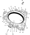
- the sealing flange has an annular support 1, which consists of hard plastic.
- Suitable plastics for the carrier 1 are, for example, high-performance thermoplastics such as PPS, suitable polyamides or PPA, but also thermosets, such as phenolic resins.
- the high-performance thermoplastics and the thermosets are each compounds containing additives depending on the application, such as glass or carbon fibers, mineral fillers and the like.
- transverse attachment points 2 to 7 which are each provided with at least one passage opening 8 for screws with which the sealing flange can be screwed to the crankcase.
- the arrangement and design of the attachment points 2 to 7 depends on the design of the respective crankcase. The in the FIGS. 1 and 2 illustrated training and arrangement of the mounting tabs 2 to 7 is therefore not to be regarded as limiting, but represents only one possible embodiment.
- At its side facing the crankcase (not shown) side surface of the sealing flange or the carrier 1 is provided with at least one static seal, which may be formed as a sealing ring and extend over the circumference of the carrier 1.
- the static seal is secured in a groove on the front side of the carrier 1 in a known manner. Since such static seals are known on sealing flanges for crankshafts, their design and arrangement will not be described in detail.
- the carrier 1 has a passage opening 22 in which a dynamic seal 11 is arranged in a known manner. It extends over the circumference of the passage opening 22 and is sealingly against the crankshaft which extends through the carrier 1.
- the dynamic seal 11 may be an elastomeric seal.
- the dynamic seal 11 is made of polyfluorocarbon, in particular polytetrafluoroethylene.
- the dynamic seal 11 is made of friction-minimized materials, so that the wear and the friction losses of the dynamic seal 11 is minimal and in this way a long life is ensured.
- the passage opening 22 has at the transition to the in the Fig. 1 and 2 shown side surface of the sealing flange on a radially outwardly conically opening wall portion 10, to which a circumferential, flat and lying in the side surface annular surface 9 connects. It advantageously has the same radial width over most of its circumference and is widened in the sensor region 23 and in the foot region 24 of the sealing flange.
- the annular surface 9 may also have a different design depending on the shape and / or design of the sealing flange.
- the illustrated and described shape of the annular surface 9 is therefore not to be understood as limiting.
- the sealing flange is provided with a speed and position sensor 12 (hereinafter referred to as sensor), which is used for the engine control and with one rotatably seated on the crankshaft encoder wheel cooperates in a known manner.
- the sensor 12 consists essentially of an electronic assembly 13 which is integrated in the sealing flange.
- the electronic assembly 13 is first inserted into the injection mold and then encapsulated in the injection molding with the plastic.
- Corresponding positioning aids for the electronic assembly 13 are arranged in the injection molding tool, so that it is arranged with exact position in the injection-molded sealing flange.
- the sensor 12 has a transversely projecting from the carrier 1 female part 14 into which a plug of a corresponding sensor line can be inserted.
- This bushing part 14 is also produced during injection molding of the sealing flange, so that it does not have to be mounted separately on the carrier 1 of the sealing flange.
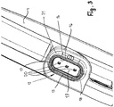
- the socket part 14 has parallel straight straight wall sections 15, 16 (FIG. Fig. 3 ), which merge at their ends via curved wall sections 17, 18 into each other.
- the receiving part 14 has a bottom 19, from which contacts 20 protrude, which are conductively connected to the electronic module 13 and which cooperate with corresponding mating contacts of the socket to be plugged into the connector 14 of the sensor line.
- the sensor 12 is arranged on the annular support 1 so that it is located in the area adjacent to the dynamic seal 11. This allows the sensor 12 to cooperate reliably with the sender wheel of the crankshaft.
- the shape of the female part 14 depends on the installation conditions in the vehicle.
- the female part 14 extends straight.
- it can also be curved, z-shaped over its length or shaped in some other way, depending on the existing installation conditions in the vehicle.
- the socket part 14 is based on a base body 21, which in the illustrated embodiment has a larger cross-section than the socket part 14.
- the main body 21 extends approximately over the entire axial width of the carrier 1.
- the electronic assembly 13 is located in the region of this base body 21, the also protrudes transversely from the annular support 1 and is integrally formed with it. Due to the large cross-sectional width of the base body 21, the electronic assembly 13 is reliably protected. Since the electronic assembly 13 is poured in the injection molding in the carrier 1 of the sealing flange, there is an excellent radial, tangential and axial positioning of the assembly 13. Since it is embedded in the material of the sealing flange, it is insensitive to vibrations and shocks. This contributes to the high measurement accuracy of the sensor 12.
- the female part 14 and the main body 21 may also have the same or substantially the same cross section. Even in such a case, the assembly 13 is reliably protected.
- the sensor 12 does not have to be subsequently mounted on the sealing flange or its carrier 1 as a separate structural unit, no guides are required for the sensor, which would lead to interruptions in the wall section 10 and in the annular surface 9. Due to the closed surfaces 9, 10 no deposits in cavities and the like. Formed, as they occur in conventional sealing flanges, in which the sensor 12 is screwed to the carrier 1. Conversely, it is ensured by the closed surfaces 9, 10 that no dirt particles are drawn from the outside into the inner region of the sealing flange.
- the overpressure bell checks the tightness of the sealing flange. It is attached to an end face of the sealing flange so that it seals over its circumference both on the annular surface 9 and on the wall section 10 the carrier 1 can rest. If an overpressure is now applied via the overpressure bell, then the overpressure must be maintained for a predetermined time. If this is the case, then this is an indication of the tightness of the sealing flange. However, if the overpressure falls within the specified measuring time, this indicates that the sealing flange has leaks. Since the surfaces 9, 10 are closed, the leak test can be made simple and reliable.
- the sealing flange is characterized by a low weight, because the additional, previously required for attaching the sensor fasteners that are made of metal, have been eliminated.
- the sealing flange with integrated injection-molded sensor 12 can be manufactured in any suitable size.
- the positioning of the sensor 12 on the sealing flange can be arbitrary, so that a wide variety of sealing flanges can be used for a variety of engine designs.
- the assembly 13 only needs to be positioned in place within the injection molding tool. During the subsequent injection molding process, the sensor 12 is then in the correct position of the sealing flange.
- the sensor 12 is designed so that the sensor signals are sent via lines to the engine control.
- the signal transmission can also be wireless, for example via radio.
Landscapes
- Engineering & Computer Science (AREA)
- General Engineering & Computer Science (AREA)
- Mechanical Engineering (AREA)
- Physics & Mathematics (AREA)
- General Physics & Mathematics (AREA)
- Chemical & Material Sciences (AREA)
- Combustion & Propulsion (AREA)
- Electromagnetism (AREA)
- Measurement Of Length, Angles, Or The Like Using Electric Or Magnetic Means (AREA)
- Transmission And Conversion Of Sensor Element Output (AREA)
Description
- Die Erfindung betrifft einen Kurbelwellen-Dichtflansch nach dem Oberbegriff des Anspruches 1.
- Kurbelwellen-Dichtflansche dienen zur Abdichtung von Kurbelwellen in Kraftfahrzeugen. Die Dichtflansche werden an die entsprechenden Kurbelgehäuse angeschraubt. Durch den Durchgang des Trägers des Dichtflansches verläuft die Kurbelwelle, an deren Umfang die dynamische Dichtung dichtend anliegt. Um die Drehzahl sowie die Position der Kurbelwelle zu erfassen, ist der Dichtflansch mit einem Sensor versehen, der mit einem drehfest auf der Kurbelwelle sitzenden Geberrad zusammenwirkt. Der Sensor ist eine gesonderte Baueinheit, die an den Träger angeschraubt wird. Damit der Sensor eine genaue Position einnimmt, ist am Träger eine radiale Führung für den Sensor vorgesehen, die sich in der einen Seitenfläche des Dichtflansches befindet und bis in die Innenwand des Trägers erstreckt. Ist der Sensor montiert, verbleibt zwischen ihm und der Seitenwand der Führung ein Spalt, der sich von der Innenwand des Trägers aus nach außen erstreckt.
- Da der Sensor an den Träger angeschraubt wird, ist es aufwändig, den Sensor in eine exakte Position bezüglich des Dichtflansches bzw. des Trägers zu bringen, weil beim Anziehen der Schraube es sich nicht vermeiden lässt, dass sich die ohnehin toleranzbehaftete Position des Sensors radial, tangential sowie auch axial ändert. Auch ist die Sensoranbindung schwingungs- und erschütterungsempfindlich, wodurch die Messgenauigkeit beeinträchtigt werden kann. Zur Verbindung des Sensors mit dem Dichtflansch Verbindungselemente notwendig, die nicht nur die Herstellung des Dichtflansches verteuern, sondern auch zu einer umständlichen und aufwändigen Montage führen. Als Verbindungselemente sind die Schraube sowie die Zentrierbuchse am Sensor erforderlich. Am Dichtflansch muss ein Gewinde-Zentriereinsatz vorgesehen werden, in den die Schraube zur Befestigung des Sensors geschraubt wird.
- Der radial verlaufende Spalt zwischen der Führungswand und dem Sensor führt dazu, dass sich in diesem Bereich mit der Zeit Ablagerungen bilden, die beim Einsatz des Dichtflansches unerwünscht sind. Außerdem kann über diesen radialen Spalt auch Schmutz von außen in den Dichtflansch eingetragen werden. Die Verbindungselemente führen dazu, dass der Sensorbereich eine gewisse Größe hat und dementsprechend einen großen Bauraum benötigt. Aufgrund des radialen Spaltes bilden sich im Einsatz des Dichtflansches Verwirbelungen im Bereich des Sensors, wodurch die Messgenauigkeit und die Dichtfunktion beeinträchtigt wird.
- Der Erfindung liegt die Aufgabe zugrunde, den gattungsgemäßen Kurbelwellen-Dichtflansch so auszubilden, dass er bei einfacher und kostengünstiger Fertigung eine zuverlässige Messung des Sensors sowie eine zuverlässige Prüfung der Dichtheit des Dichtflansches ermöglicht.
- Diese Aufgabe wird beim gattungsgemäßen Kurbelwellen-Dichtflansch erfindungsgemäß mit den kennzeichnenden Merkmalen des Anspruches 1 gelöst.
- Beim erfindungsgemäßen Kurbelwellen-Dichtflansch ist der Sensor kein gesondertes Bauteil, das mittels Verbindungselementen am Dichtflansch montiert werden muss. Vielmehr ist der Sensor bzw. seine elektronische Baugruppe in den Kunststoff des Trägers integriert. Da die Baugruppe in den Kunststoff eingebettet ist, ist sie geschützt am Dichtflansch vorgesehen. Die elektronische Baugruppe und damit der Sensor können mit hoher radialer, tangentialer und axialer Genauigkeit am Dichtflansch vorgesehen werden. Die Integration des Sensors bzw. seiner elektronischen Baugruppe zeichnet sich durch eine sehr hohe Schwingungs- und Erschütterungsunempfindlichkeit aus, was zur hohen Messgenauigkeit beiträgt.
- Da die elektronische Baugruppe in den Kunststoff integriert ist, müssen am Träger keine Führungen und dgl. vorgesehen sein, um eine Lagepositionierung des Sensors zu erreichen. Die erfindungsgemäße Ausbildung führt zu einer kompakten Gestaltung des Dichtflansches, der dadurch auch dann eingesetzt werden kann, wenn der vorhandene Einbauraum im jeweiligen Fahrzeug klein ist.
- Vorteilhaft wird die elektronische Baugruppe bei der Herstellung des Dichtflansches durch Spritzgießen vorkonfektioniert in das Spritzgusswerkzeug eingelegt und anschließend der Kunststoff eingespritzt. Der dem Spritzgusswerkzeug zu entnehmende Dichtflansch weist somit bereits integriert die elektronische Baugruppe auf.
- Da für die genaue Positionierung des Sensors keine Führung mehr erforderlich ist, kann der Durchgang des Trägers in vorteilhafter Weise einen umlaufend geschlossenen Wandabschnitt aufweisen, an den eine umlaufende, ebene Ringfläche in der einen Seitenfläche des Trägers anschließt. Dadurch entfallen beispielsweise radial verlaufende Spalte, die in die Innenwand des Durchganges münden. Dadurch werden auf einfache Weise Aufnahmeräume vermieden, in denen sich während des Einsatzes des Dichtflansches Ablagerungen bilden können. Darüber hinaus haben der geschlossene Wandabschnitt des Durchganges und die geschlossene Ringfläche insbesondere den Vorteil, dass eine Dichtheitsprüfung mittels einer Überdruckglocke zuverlässig und einfach möglich ist. Aufgrund der geschlossenen Flächen kann die Überdruckglocke dichtend so aufgesetzt werden, dass über den gesamten Umfang eine einwandfreie Abdichtung gegeben ist. Wird der Überdruck bei der Prüfung aufgebracht, dann tritt nicht mehr das Problem auf, dass die Luft unbeabsichtigt durch in die Innenwand des Durchganges mündende Spalte nach außen abgeführt werden kann. Wenn darum bei der Prüfung ein Druckabfall innerhalb der Messzeit auftritt, dann ist dies ein sicheres Anzeichen dafür, dass der Dichtflansch undicht ist.
- Die elektronische Baugruppe ist innerhalb des Trägers so angeordnet, dass der Abstand von der Innenseite des Trägers so gering ist, dass der Sensor mit dem Geberrad auf der Kurbelwelle zusammenwirken kann. Die elektronische Baugruppe ist somit auch gegen die Innenwand des Trägers geschützt und abgedichtet.
- Der Sensor weist vorteilhaft einen vom Träger abstehenden Buchsenteil auf, in den ein Stecker einer Sensorleitung gesteckt werden kann, mit der die Sensorsignale einer Steuereinrichtung, beispielsweise einer Motorsteuerung, zugeführt werden können.
- Auch der Buchsenteil ist einstückig mit dem Träger ausgebildet und wird vorzugsweise beim Spritzgießen am Träger vorgesehen.
- Vorteilhaft ragt die elektronische Baugruppe bis in einen Grundkörper, von dem der Buchsenteil absteht. Der Grundkörper ist massiv ausgebildet und schützt die elektronische Baugruppe zuverlässig.
- Zum sicheren Schutz und zur sicheren Befestigung der elektronischen Baugruppe trägt in vorteilhafter Weise bei, wenn sich der Grundkörper zumindest annähernd über die axiale Breite des Trägers erstreckt.
- Die dynamische Dichtung, mit welcher der Dichtflansch dichtend an der Kurbelwelle anliegt, kann aus geeigneten Kunststoffen, vorteilhaft aus Polyfluorcarbon, vorzugsweise aus Polytetrafluorethylen, bestehen. Dieser Werkstoff weist nur geringe Reibungswerte auf, so dass eine lange Einsatzdauer des Dichtflansches gewährleistet ist.
- Die dynamische Dichtung kann aber auch aus elastomeren Werkstoffen, z. B. in Form einer flächig anliegenden Lippendichtung, oder in einer klassischen Lippendichtausbildung (Dichtkante mit Federkraftunterstützung) bestehen.
- Um eine statische Abdichtung des Dichtflansches am Kurbelgehäuse zu gewährleisten, ist es vorteilhaft, wenn der Träger an seiner dem Kurbelgehäuse zugewandten Seitenfläche wenigstens eine statische Dichtung aufweist. Mit ihr wird der Dichtflansch gegenüber dem Kurbelgehäuse zuverlässig abgedichtet.
- Der Träger selbst besteht vorteilhaft aus Hochleistungs-Thermoplasten oder Duroplasten.
- Als Hochleistungs-Thermoplaste kommen beispielsweise PPS, geeignete Polyamide oder PPA in Betracht. Als Duroplast sind vorteilhaft Phenolharze gut geeignet. Bei den Thermoplasten und Duroplasten handelt es sich jeweils um Compounds, d.h. sie weisen je nach Anwendungsfall beispielsweise Glas- oder Karbonfasern, mineralische Füllstoffe und dgl. auf.
- Der Sensor kann seine Sensorsignale über Leitungen oder kabellos an eine Steuerung, vorzugsweise eine Motorsteuerung, übertragen.
- Der Anmeldungsgegenstand ergibt sich nicht nur aus dem Gegenstand der einzelnen Ansprüche, sondern auch durch alle in den Zeichnungen und der Beschreibung offenbarten Angaben und Merkmale. Sie werden, auch wenn sie nicht Gegenstand der Ansprüche sind, als erfindungswesentlich beansprucht, soweit sie einzeln oder in Kombination gegenüber dem Stand der Technik neu sind.
- Weitere Merkmale der Erfindung ergeben sich aus den weiteren Ansprüchen, der Beschreibung und den Zeichnungen.
- Die Erfindung wird anhand eines in den Zeichnungen dargestellten Ausführungsbeispieles näher erläutert. Es zeigen
- Fig. 1
- in perspektivischer Darstellung einen erfindungsgemäßen Kurbelwellen-Dichtflansch,
- Fig. 2
- den erfindungsgemäßen Kurbelwellen-Dichtflansch in Vorderansicht,
- Fig. 3
- in vergrößerter und perspektivischer Darstellung den Sensoreingang des erfindungsgemäßen Kurbelwellen-Dichtflansches (Pfeil III in
Fig. 2 ). - Der Dichtflansch dient zur Abdichtung von PKW- und LKW-Kurbelwellen vorn und hinten. Die Dichtflansche werden in bekannter Weise an Gehäuse angeschraubt, in welchen die Kurbelwelle drehbar gelagert ist.
- Der Dichtflansch hat einen ringförmigen Träger 1, der aus hartem Kunststoff besteht. Als Kunststoffe für den Träger 1 kommen beispielhaft Hochleistungs-Thermoplaste, wie PPS, geeignete Polyamide oder PPA, aber auch Duroplaste in Betracht, wie etwa Phenolharze. Die Hochleistungs-Thermoplaste sowie die Duroplaste sind jeweils Compounds, die je nach Einsatzfall Zusätze, wie Glas- oder Karbonfasern, mineralische Füllstoffe und dergleichen enthalten.
- Vom Träger 1 stehen quer Befestigungspunkte 2 bis 7 ab, die jeweils mit wenigstens einer Durchtrittsöffnung 8 für Schrauben versehen sind, mit denen der Dichtflansch an das Kurbelgehäuse angeschraubt werden kann. Die Anordnung und Ausbildung der Befestigungspunkte 2 bis 7 richtet sich nach der Bauform des jeweiligen Kurbelgehäuses. Die in den
Figuren 1 und2 dargestellte Ausbildung und Anordnung der Befestigungslaschen 2 bis 7 ist darum nicht als beschränkend anzusehen, sondern stellt nur ein mögliches Ausführungsbeispiel dar. - An seiner dem Kurbelgehäuse zugewandten (nicht dargestellten) Seitenfläche ist der Dichtflansch bzw. der Träger 1 mit wenigstens einer statischen Dichtung versehen, die als Dichtring ausgebildet sein und über den Umfang des Trägers 1 verlaufen kann. Die statische Dichtung ist in einer Nut an der Stirnseite des Trägers 1 in bekannter Weise befestigt. Da solche statischen Dichtungen an Dichtflanschen für Kurbelwellen bekannt sind, wird ihre Ausbildung und Anordnung nicht näher beschrieben.
- Der Träger 1 hat eine Durchgangsöffnung 22, in der in bekannter Weise eine dynamische Dichtung 11 angeordnet ist. Sie erstreckt sich über den Umfang der Durchgangsöffnung 22 und liegt dichtend an der Kurbelwelle an, die sich durch den Träger 1 erstreckt. Die dynamische Dichtung 11 kann eine Elastomerdichtung sein. Vorteilhaft besteht die dynamische Dichtung 11 aus Polyfluorcarbon, insbesondere aus Polytetrafluorethylen. Die dynamische Dichtung 11 besteht aus reibungsminimierten Werkstoffen, so dass der Verschleiß und die Reibungsverluste der dynamischen Dichtung 11 minimal ist und auf diese Weise eine lange Lebensdauer sichergestellt ist.
- Die Durchgangsöffnung 22 weist am Übergang zu der in den
Fig. 1 und2 dargestellten Seitenfläche des Dichtflansches einen radial nach außen konisch sich öffnenden Wandabschnitt 10 auf, an den eine umlaufende, ebene und in der Seitenfläche liegende Ringfläche 9 anschließt. Sie hat über den größten Teil ihres Umfanges vorteilhaft gleiche radiale Breite und ist im Sensorbereich 23 sowie im Fußbereich 24 des Dichtflansches verbreitert ausgebildet. - Die Ringfläche 9 kann in Abhängigkeit von der Form und/oder Ausbildung des Dichtflansches auch eine andere Gestaltung aufweisen. Die dargestellte und beschriebene Form der Ringfläche 9 ist darum nicht einschränkend zu verstehen.
- Der Dichtflansch ist mit einem Drehzahl- und Positionssensor 12 (nachfolgend Sensor bezeichnet) versehen, der für die Motorsteuerung dient und mit einem auf der Kurbelwelle drehfest sitzenden Geberrad in bekannter Weise zusammenwirkt. Der Sensor 12 besteht im Wesentlichen aus einer elektronischen Baugruppe 13, die in den Dichtflansch integriert ist. Beim Spritzgießen des Dichtflansches wird die elektronische Baugruppe 13 zunächst in das Spritzgusswerkzeug eingelegt und anschließend beim Spritzgießvorgang mit dem Kunststoff umspritzt. Im Spritzgusswerkzeug werden entsprechende Positionierhilfen für die elektronische Baugruppe 13 angeordnet, so dass diese positionsgenau im spritzgegossenen Dichtflansch angeordnet ist.
- Der Sensor 12 hat einen quer vom Träger 1 abstehenden Buchsenteil 14, in den ein Stecker einer entsprechenden Sensorleitung gesteckt werden kann. Auch dieser Buchsenteil 14 wird beim Spritzgießen des Dichtflansches hergestellt, so dass er nicht gesondert am Träger 1 des Dichtflansches montiert werden muss. Im Ausführungsbeispiel hat der Buchsenteil 14 parallel zueinander liegende gerade Wandabschnitte 15, 16 (
Fig. 3 ), die an ihren Enden über gekrümmte Wandabschnitte 17, 18 ineinander übergehen. - Der Aufnahmeteil 14 hat einen Boden 19, aus dem Kontakte 20 ragen, die mit der elektronischen Baugruppe 13 leitungsverbunden sind und die mit entsprechenden Gegenkontakten des in den Buchsenteil 14 zu steckenden Steckers der Sensorleitung zusammenwirken.
- Der Sensor 12 ist so am ringförmigen Träger 1 angeordnet, dass er sich im Bereich neben der dynamischen Dichtung 11 befindet. Dadurch kann der Sensor 12 zuverlässig mit dem Geberrad der Kurbelwelle zusammenwirken.
- Die Form des Buchsenteils 14 richtet sich nach den Einbauverhältnissen im Fahrzeug. Im dargestellten Ausführungsbeispiel erstreckt sich der Buchsenteil 14 gerade. Er kann beispielsweise über seine Länge auch gekrümmt, z-förmig gestaltet oder in anderer Weise geformt sein, je nach den vorhandenen Einbauverhältnissen im Fahrzeug.
- Der Buchsenteil 14 steht von einem Grundkörper 21 ab, der im dargestellten Ausführungsbeispiel größeren Querschnitt hat als der Buchsenteil 14. Der Grundkörper 21 erstreckt sich etwa über die gesamte axiale Breite des Trägers 1. Die elektronische Baugruppe 13 befindet sich im Bereich dieses Grundkörpers 21, der ebenfalls quer vom ringförmigen Träger 1 absteht und einstückig mit ihm ausgebildet ist. Aufgrund der großen Querschnittsbreite des Grundkörpers 21 ist die elektronische Baugruppe 13 zuverlässig geschützt. Da die elektronische Baugruppe 13 beim Spritzgießvorgang in den Träger 1 des Dichtflansches eingegossen wird, ergibt sich eine hervorragende radiale, tangentiale und axiale Positionierung der Baugruppe 13. Da sie in das Material des Dichtflansches eingebettet ist, ist sie gegen Schwingungen und Erschütterungen unempfindlich. Dies trägt zur hohen Messgenauigkeit des Sensors 12 bei.
- Der Buchsenteil 14 und der Grundkörper 21 können auch gleichen oder im Wesentlichen gleichen Querschnitt haben. Auch in einem solchen Fall ist die Baugruppe 13 zuverlässig geschützt.
- Da der Sensor 12 nicht als gesonderte Baueinheit nachträglich am Dichtflansch bzw. seinem Träger 1 montiert werden muss, sind keine Führungen für den Sensor erforderlich, die zu Unterbrechungen im Wandabschnitt 10 und in der Ringfläche 9 führen würden. Aufgrund der geschlossenen Flächen 9, 10 können sich keine Ablagerungen in Hohlräumen und dgl. bilden, wie sie bei herkömmlichen Dichtflanschen auftreten, bei denen der Sensor 12 an den Träger 1 angeschraubt wird. Umgekehrt wird durch die geschlossenen Flächen 9, 10 sichergestellt, dass keine Schmutzteilchen von außen in den Innenbereich des Dichtflansches eingezogen werden.
- Diese geschlossenen Flächen 9, 10 sind insbesondere bei der Dichtheitsprüfung des Dichtflansches mit Hilfe einer Überdruckglocke von Vorteil. Mit der Überdruckglocke wird die Dichtheit des Dichtflansches überprüft. Sie wird an eine Stirnseite des Dichtflansches so angesetzt, dass sie über ihren Umfang dichtend sowohl an der Ringfläche 9 als auch am Wandabschnitt 10 des Trägers 1 anliegen kann. Wird nun über die Überdruckglocke ein Überdruck aufgebracht, dann muss der Überdruck über eine vorgegebene Zeit aufrecht erhalten bleiben. Ist dies der Fall, dann ist dies ein Hinweis auf die Dichtheit des Dichtflansches. Sinkt jedoch der Überdruck innerhalb der vorgegebenen Messzeit, deutet dies darauf hin, dass der Dichtflansch Undichtigkeiten aufweist. Da die Flächen 9, 10 geschlossen sind, kann die Dichtheitsprüfung einfach und zuverlässig vorgenommen werden. Tritt ein Druckabfall innerhalb der vorgegebenen Messzeit auf, kann mit Sicherheit davon ausgegangen werden, dass der Dichtflansch undicht ist. Mit der beschriebenen Ausbildung des Dichtflansches kann das Luftleckageaufkommen sehr präzise gemessen werden. Es ist dadurch sogar in vorteilhafter Weise möglich, auf eine Beölung der Kurbelwelle bei der Montage des Dichtflansches zu verzichten, was bei den herkömmlichen Dichtflanschen mit angeschraubtem Sensor erforderlich ist.
- Da die elektronische Baugruppe 13 in den Träger 1 des Dichtflansches integriert ist, ergeben sich sehr präzise Ergebnisse bei der Drehzahl- und Positionsmessung der Kurbelwelle. Dies ist darauf zurückzuführen, dass die mit angeschraubten Sensoren verbundenen Probleme eines Dichtflansches infolge des integrierten Sensors 12 vermieden werden. Es entfallen vor allem Montage- und Fertigungstoleranzen, die zu ungenauen Positionen des Sensors in Bezug auf das Geberrad der Kurbelwelle führen. Die Lage der Sensormimik in Bezug auf das Geberrad innerhalb des Dichtflansches ist infolge der Einbettung in das Material des Dichtflansches sehr präzise sowie schwingungs- und erschütterungsunempfindlich.
- Durch den Wegfall des separaten Sensors und die Integration der elektronischen Baugruppe 13 in den Träger 1 bzw. den Dichtflansch reduziert sich nicht nur das Gesamtgewicht des Dichtflansches 12, sondern es entfallen auch zusätzliche Montagevorgänge, um den Sensor mit dem Dichtflansch zu verbinden. Damit entfallen aber auch die bisher notwendigen Verbindungselemente, wie Schraube, Zentrierbuchse und Gewindeeinsatz aus Metall. Durch den Wegfall dieser zusätzlichen Teile ergibt sich eine sehr kostengünstige Herstellung des Dichtflansches. Da die genannten Verbindungselemente aus Metall bestehen, werden infolge der Einbettung der elektronischen Baugruppe 13 in den Dichtflansch Ressourcen geschont. Auch wird Kunststoff eingespart, weil für den Sensor keine eigene Haltevorrichtung erforderlich ist. Der Wegfall des gesondert am Dichtflansch zu montierenden Sensors führt auch zu einer erheblichen Kompaktheit des Dichtflansches. Er nimmt dadurch nur wenig Bauraum in Anspruch und kann darum in solchen Fahrzeugen vorteilhaft eingesetzt werden, bei denen nur wenig Bauraum für den Dichtflansch zur Verfügung steht. Zudem zeichnet sich der Dichtflansch durch ein geringes Gewicht aus, weil die zusätzlichen, zur Befestigung des Sensors bislang erforderlichen Verbindungselemente, die aus Metall bestehen, weggefallen sind.
- Der Dichtflansch mit spritzgusstechnisch integriertem Sensor 12 kann in jeder geeigneten Größe gefertigt werden. Auch die Positionierung des Sensors 12 am Dichtflansch kann beliebig sein, so dass unterschiedlichste Dichtflansche für unterschiedlichste Motorgestaltungen verwendet werden können. Die Baugruppe 13 muss lediglich innerhalb des Spritzgusswerkzeuges an der richtigen Stelle positioniert werden. Beim anschließenden Spritzgussvorgang befindet sich dann der Sensor 12 an der richtigen Stelle des Dichtflansches.
- Im beschriebenen Ausführungsbeispiel ist der Sensor 12 so ausgebildet, dass die Sensorsignale über Leitungen an die Motorsteuerung gesendet werden. Die Signalübertragung kann aber auch drahtlos erfolgen, beispielsweise über Funk.
Claims (10)
- Kurbelwellen-Dichtflansch mit einem Träger, der wenigstens teilweise aus Kunststoff besteht und wenigstens eine dynamische Dichtung aufweist, die über den Umfang einer Innenwand eines Durchganges des Trägers verläuft, und mit wenigstens einem zur Erfassung der Drehzahl und der Position der Kurbelwelle vorgesehenen Sensor, der im Wesentlichen aus einer elektronischen Baugruppe besteht,
dadurch gekennzeichnet, dass die elektronische Baugruppe (13) des Sensors (12) in den Kunststoff des Trägers (1) integriert ist. - Dichtflansch nach Anspruch 1,
dadurch gekennzeichnet, dass die elektronische Baugruppe (13) des Sensors (12) beim Spritzgießen des Dichtflansches in den Kunststoff integriert wird. - Dichtflansch nach Anspruch 1 oder 2,
dadurch gekennzeichnet, dass der Durchgang (22) einen umlaufenden geschlossenen Wandabschnitt (10) aufweist, an den eine umlaufende, ebene Ringfläche (9) in der einen Seitenfläche des Trägers (1) anschließt. - Dichtflansch nach einem der Ansprüche 1 bis 3,
dadurch gekennzeichnet, dass die elektronische Baugruppe (13) innerhalb des Trägers (1) einen solchen Abstand von der Innenwand des Durchganges (22) des Trägers (1) hat, dass der Sensor (12) mit einem Geberrad auf der Kurbelwelle zusammenwirken kann. - Dichtflansch nach einem der Ansprüche 1 bis 4,
dadurch gekennzeichnet, dass der Sensor (12) einen vom Träger (1) abstehenden Buchsenteil (14) für einen Stecker einer Sensorleitung aufweist. - Dichtflansch nach Anspruch 5,
dadurch gekennzeichnet, dass die elektronische Baugruppe (13) bis in einen Grundkörper (21) ragt, von dem der Buchsenteil (14) absteht. - Dichtflansch nach Anspruch 6,
dadurch gekennzeichnet, dass der Grundkörper (21) sich zumindest annähernd über die axiale Breite des Trägers (1) erstreckt. - Dichtflansch nach einem der Ansprüche 1 bis 7,
dadurch gekennzeichnet, dass der Träger (1) an einer seiner Seitenflächen wenigstens eine statische Dichtung aufweist. - Dichtflansch nach einem der Ansprüche 1 bis 8,
dadurch gekennzeichnet, dass der Träger (1) aus Hochleistungs-Thermoplasten oder aus Duroplasten besteht. - Dichtflansch nach einem der Ansprüche 1 bis 9,
dadurch gekennzeichnet, dass der Sensor (12) über Leitungen oder kabellos die Sensorsignale an eine Steuerung, vorzugsweise eine Motorsteuerung, sendet.
Applications Claiming Priority (1)
| Application Number | Priority Date | Filing Date | Title |
|---|---|---|---|
| DE202015007951.2U DE202015007951U1 (de) | 2015-11-16 | 2015-11-16 | Kurbelwellen-Dichtflansch |
Publications (2)
| Publication Number | Publication Date |
|---|---|
| EP3208454A1 true EP3208454A1 (de) | 2017-08-23 |
| EP3208454B1 EP3208454B1 (de) | 2020-06-03 |
Family
ID=54867323
Family Applications (1)
| Application Number | Title | Priority Date | Filing Date |
|---|---|---|---|
| EP16002339.6A Active EP3208454B1 (de) | 2015-11-16 | 2016-11-03 | Kurbelwellen-dichtflansch |
Country Status (4)
| Country | Link |
|---|---|
| US (1) | US10024433B2 (de) |
| EP (1) | EP3208454B1 (de) |
| CN (1) | CN106704383B (de) |
| DE (1) | DE202015007951U1 (de) |
Cited By (1)
| Publication number | Priority date | Publication date | Assignee | Title |
|---|---|---|---|---|
| FR3154153A1 (fr) | 2023-10-13 | 2025-04-18 | Psa Automobiles Sa | Plaque metallique configuree pour assurer l’etancheite d’un moteur comprenant un joint dynamique pourvu d’au moins un segment d’arrêt aimante |
Families Citing this family (2)
| Publication number | Priority date | Publication date | Assignee | Title |
|---|---|---|---|---|
| WO2022127974A1 (de) * | 2020-12-15 | 2022-06-23 | Schaeffler Technologies AG & Co. KG | Sensorlager mit duroplastmantel für die winkelerfassung von einer welle sowie verfahren zur fertigung des sensorlagers |
| CN115263596A (zh) * | 2022-07-25 | 2022-11-01 | 东风汽车集团股份有限公司 | 发动机 |
Citations (4)
| Publication number | Priority date | Publication date | Assignee | Title |
|---|---|---|---|---|
| EP1063455A2 (de) * | 1999-06-23 | 2000-12-27 | CR Elastomere GmbH | Dichtflansch zur Abdichtung von einem sich drehenden Maschinenteil |
| FR2828931A1 (fr) * | 2001-08-21 | 2003-02-28 | Skf Ab | Unite de montage pour systemes transmetteurs de position angulaire, par exemple de position angulaire d'un vilebrequin de vehicule automobile |
| EP1780549A2 (de) * | 2005-11-01 | 2007-05-02 | Jtekt Corporation | Dichtungsanordnung mit einem Sensor und Wälzlagervorrichtung mit einer solchen Dichtungsanordnung |
| CN203703137U (zh) * | 2014-03-10 | 2014-07-09 | 董波 | 具有传感功能的总成油封 |
Family Cites Families (13)
| Publication number | Priority date | Publication date | Assignee | Title |
|---|---|---|---|---|
| SE452639B (sv) * | 1984-12-20 | 1987-12-07 | Saab Scania Ab | Arrangemang vid en forbrenningsmotor for anslutning av en legesavkennande givare |
| US5152538A (en) * | 1988-03-21 | 1992-10-06 | Chicago Rawhide Manufacturing Company, Inc. | Composite seal assembly |
| DE19605550C2 (de) * | 1996-02-15 | 1999-07-08 | Freudenberg Carl Fa | Radialwellendichtring |
| BR9604203A (pt) * | 1996-10-16 | 1998-05-26 | Sabo Ind & Comercio Ltda | Aperfeiçoamento em vedação |
| DE19839297C2 (de) * | 1998-08-28 | 2001-06-21 | Freudenberg Carl Fa | Dichtungsanordnung |
| NO322272B1 (no) * | 1999-03-26 | 2006-09-04 | Kongsberg Maritime As | Sensor og system for overvaking av temperatur inne i vanskelig tilgjengelige, bevegelige deler |
| JP4141588B2 (ja) * | 1999-06-02 | 2008-08-27 | 株式会社ジェイテクト | 車輪速検出装置 |
| DE19951340C2 (de) * | 1999-10-25 | 2002-07-18 | Freudenberg Carl Kg | Dichtungsanordnung |
| US7334555B2 (en) * | 2004-02-02 | 2008-02-26 | Freudenberg-Nok General Partnership | Stamped crankshaft seal retainer plate and molded encoder sensor support feature |
| US7341257B2 (en) * | 2004-04-15 | 2008-03-11 | Federal-Mogul World Wide, Inc | Integrated sensor-seal module for detecting angular position of a crankshaft |
| JP2006009979A (ja) * | 2004-06-28 | 2006-01-12 | Nok Corp | センサ付き密封装置 |
| DE102010028232A1 (de) * | 2010-04-27 | 2011-10-27 | Robert Bosch Gmbh | Sensorbaugruppe für ein Fahrzeug und Vorrichtung zur Erfassung von Drehbewegungen eines Radlagers |
| DE102014200273B4 (de) * | 2014-01-10 | 2018-04-19 | Ford Global Technologies, Llc | Lagerkappe |
-
2015
- 2015-11-16 DE DE202015007951.2U patent/DE202015007951U1/de not_active Expired - Lifetime
-
2016
- 2016-11-03 EP EP16002339.6A patent/EP3208454B1/de active Active
- 2016-11-15 US US15/351,631 patent/US10024433B2/en active Active
- 2016-11-16 CN CN201611034189.1A patent/CN106704383B/zh active Active
Patent Citations (4)
| Publication number | Priority date | Publication date | Assignee | Title |
|---|---|---|---|---|
| EP1063455A2 (de) * | 1999-06-23 | 2000-12-27 | CR Elastomere GmbH | Dichtflansch zur Abdichtung von einem sich drehenden Maschinenteil |
| FR2828931A1 (fr) * | 2001-08-21 | 2003-02-28 | Skf Ab | Unite de montage pour systemes transmetteurs de position angulaire, par exemple de position angulaire d'un vilebrequin de vehicule automobile |
| EP1780549A2 (de) * | 2005-11-01 | 2007-05-02 | Jtekt Corporation | Dichtungsanordnung mit einem Sensor und Wälzlagervorrichtung mit einer solchen Dichtungsanordnung |
| CN203703137U (zh) * | 2014-03-10 | 2014-07-09 | 董波 | 具有传感功能的总成油封 |
Cited By (1)
| Publication number | Priority date | Publication date | Assignee | Title |
|---|---|---|---|---|
| FR3154153A1 (fr) | 2023-10-13 | 2025-04-18 | Psa Automobiles Sa | Plaque metallique configuree pour assurer l’etancheite d’un moteur comprenant un joint dynamique pourvu d’au moins un segment d’arrêt aimante |
Also Published As
| Publication number | Publication date |
|---|---|
| DE202015007951U1 (de) | 2015-12-07 |
| US10024433B2 (en) | 2018-07-17 |
| EP3208454B1 (de) | 2020-06-03 |
| CN106704383A (zh) | 2017-05-24 |
| US20170138481A1 (en) | 2017-05-18 |
| CN106704383B (zh) | 2020-03-31 |
Similar Documents
| Publication | Publication Date | Title |
|---|---|---|
| EP3175150B1 (de) | Hydraulische oder pneumatische betätigungsvorrichtung für die betätigung von stellgliedern in einem kraftfahrzeuggetriebe | |
| DE102008047466A1 (de) | Magnetbaugruppe für eine Drehmoment- und/oder Drehwinkelsensoranordnung mit einem Magnetring und Herstellungsverfahren | |
| DE112015000086B4 (de) | Raddrehzahlsensor und Herstellungsverfahren dafür | |
| DE102014208422A1 (de) | Radlagereinheit | |
| DE102009039082A1 (de) | Magnetbaugruppe für eine Drehmoment- und/oder Drehwinkelsensoranordnung mit einem Magnetring und Herstellungsverfahren | |
| EP3208454B1 (de) | Kurbelwellen-dichtflansch | |
| DE102012210412B4 (de) | Sensorvorrichtung mit o-ring | |
| DE102016104882A1 (de) | Wellendichtungssystem | |
| DE102011118775B3 (de) | Vorrichtung zur berührungslosen Erfassung der Relativposition zweier relativ zueinander bewegbarer Teile | |
| DE102010013214A1 (de) | Radlageranordnung mit Sensoranschlag | |
| DE102016213359A1 (de) | Lageranordnung | |
| DE102017108717A1 (de) | Scheibenbremse für ein Nutzfahrzeug | |
| DE102010028232A1 (de) | Sensorbaugruppe für ein Fahrzeug und Vorrichtung zur Erfassung von Drehbewegungen eines Radlagers | |
| WO2016124179A1 (de) | Radlagereinheit | |
| DE102009016298A1 (de) | Wegmesssystem für Kupplungsausrücksysteme | |
| DE60306869T2 (de) | Dynamische Dichtung mit Winkelkodierung für rotierende Wellen, Vorrichtung mit einer solchen Dichtungund und Herstellungsverfahren | |
| EP1503096A2 (de) | Halteelement zur Fixierung wenigstens eines Lagers | |
| DE102016121643A1 (de) | Messanordnung zur Bestimmung und/oder Überwachung zumindest einer Prozessgröße eines Mediums in einer Rohrleitung | |
| DE102009016284A1 (de) | Befestigungsanordnung | |
| WO2016091370A1 (de) | Gurtaufroller mit einem signalgeberring | |
| DE102014202354A1 (de) | Dichtvorrichtung für ein Sensorgehäuse | |
| DE102009057491A1 (de) | Drosselklappenvorrichtung | |
| DE102015104892A1 (de) | Vorrichtung zum Erfassen eines Bremsbelagverschleißes sowie Anordnung aus einem Führungsholm und einem sensierbaren Element | |
| DE102021116435A1 (de) | Sensoranordnung mit bündigen oder versenktem Aufbau, insbesondere für ein Wälzlager | |
| DE102021213854A1 (de) | Dämpfervorrichtung mit aus Kunststoff gefertigter Schutzkappe und Schutzrohr sowie Verfahren zum Herstellen der Dämpfervorrichtung |
Legal Events
| Date | Code | Title | Description |
|---|---|---|---|
| STAA | Information on the status of an ep patent application or granted ep patent |
Free format text: STATUS: UNKNOWN |
|
| PUAI | Public reference made under article 153(3) epc to a published international application that has entered the european phase |
Free format text: ORIGINAL CODE: 0009012 |
|
| STAA | Information on the status of an ep patent application or granted ep patent |
Free format text: STATUS: THE APPLICATION HAS BEEN PUBLISHED |
|
| AK | Designated contracting states |
Kind code of ref document: A1 Designated state(s): AL AT BE BG CH CY CZ DE DK EE ES FI FR GB GR HR HU IE IS IT LI LT LU LV MC MK MT NL NO PL PT RO RS SE SI SK SM TR |
|
| AX | Request for extension of the european patent |
Extension state: BA ME |
|
| STAA | Information on the status of an ep patent application or granted ep patent |
Free format text: STATUS: REQUEST FOR EXAMINATION WAS MADE |
|
| 17P | Request for examination filed |
Effective date: 20180223 |
|
| RBV | Designated contracting states (corrected) |
Designated state(s): AL AT BE BG CH CY CZ DE DK EE ES FI FR GB GR HR HU IE IS IT LI LT LU LV MC MK MT NL NO PL PT RO RS SE SI SK SM TR |
|
| RIC1 | Information provided on ipc code assigned before grant |
Ipc: F02F 7/00 20060101AFI20190709BHEP Ipc: F16J 15/326 20160101ALI20190709BHEP |
|
| GRAP | Despatch of communication of intention to grant a patent |
Free format text: ORIGINAL CODE: EPIDOSNIGR1 |
|
| STAA | Information on the status of an ep patent application or granted ep patent |
Free format text: STATUS: GRANT OF PATENT IS INTENDED |
|
| INTG | Intention to grant announced |
Effective date: 20191018 |
|
| RAP1 | Party data changed (applicant data changed or rights of an application transferred) |
Owner name: KACO GMBH + CO. KG |
|
| GRAJ | Information related to disapproval of communication of intention to grant by the applicant or resumption of examination proceedings by the epo deleted |
Free format text: ORIGINAL CODE: EPIDOSDIGR1 |
|
| STAA | Information on the status of an ep patent application or granted ep patent |
Free format text: STATUS: REQUEST FOR EXAMINATION WAS MADE |
|
| GRAJ | Information related to disapproval of communication of intention to grant by the applicant or resumption of examination proceedings by the epo deleted |
Free format text: ORIGINAL CODE: EPIDOSDIGR1 |
|
| STAA | Information on the status of an ep patent application or granted ep patent |
Free format text: STATUS: GRANT OF PATENT IS INTENDED |
|
| GRAP | Despatch of communication of intention to grant a patent |
Free format text: ORIGINAL CODE: EPIDOSNIGR1 |
|
| INTC | Intention to grant announced (deleted) | ||
| INTG | Intention to grant announced |
Effective date: 20200312 |
|
| GRAS | Grant fee paid |
Free format text: ORIGINAL CODE: EPIDOSNIGR3 |
|
| GRAA | (expected) grant |
Free format text: ORIGINAL CODE: 0009210 |
|
| STAA | Information on the status of an ep patent application or granted ep patent |
Free format text: STATUS: THE PATENT HAS BEEN GRANTED |
|
| AK | Designated contracting states |
Kind code of ref document: B1 Designated state(s): AL AT BE BG CH CY CZ DE DK EE ES FI FR GB GR HR HU IE IS IT LI LT LU LV MC MK MT NL NO PL PT RO RS SE SI SK SM TR |
|
| REG | Reference to a national code |
Ref country code: GB Ref legal event code: FG4D Free format text: NOT ENGLISH |
|
| REG | Reference to a national code |
Ref country code: CH Ref legal event code: EP Ref country code: AT Ref legal event code: REF Ref document number: 1277252 Country of ref document: AT Kind code of ref document: T Effective date: 20200615 |
|
| REG | Reference to a national code |
Ref country code: DE Ref legal event code: R096 Ref document number: 502016010094 Country of ref document: DE |
|
| REG | Reference to a national code |
Ref country code: LT Ref legal event code: MG4D |
|
| PG25 | Lapsed in a contracting state [announced via postgrant information from national office to epo] |
Ref country code: SE Free format text: LAPSE BECAUSE OF FAILURE TO SUBMIT A TRANSLATION OF THE DESCRIPTION OR TO PAY THE FEE WITHIN THE PRESCRIBED TIME-LIMIT Effective date: 20200603 Ref country code: LT Free format text: LAPSE BECAUSE OF FAILURE TO SUBMIT A TRANSLATION OF THE DESCRIPTION OR TO PAY THE FEE WITHIN THE PRESCRIBED TIME-LIMIT Effective date: 20200603 Ref country code: GR Free format text: LAPSE BECAUSE OF FAILURE TO SUBMIT A TRANSLATION OF THE DESCRIPTION OR TO PAY THE FEE WITHIN THE PRESCRIBED TIME-LIMIT Effective date: 20200904 Ref country code: FI Free format text: LAPSE BECAUSE OF FAILURE TO SUBMIT A TRANSLATION OF THE DESCRIPTION OR TO PAY THE FEE WITHIN THE PRESCRIBED TIME-LIMIT Effective date: 20200603 Ref country code: NO Free format text: LAPSE BECAUSE OF FAILURE TO SUBMIT A TRANSLATION OF THE DESCRIPTION OR TO PAY THE FEE WITHIN THE PRESCRIBED TIME-LIMIT Effective date: 20200903 |
|
| REG | Reference to a national code |
Ref country code: NL Ref legal event code: MP Effective date: 20200603 |
|
| PG25 | Lapsed in a contracting state [announced via postgrant information from national office to epo] |
Ref country code: LV Free format text: LAPSE BECAUSE OF FAILURE TO SUBMIT A TRANSLATION OF THE DESCRIPTION OR TO PAY THE FEE WITHIN THE PRESCRIBED TIME-LIMIT Effective date: 20200603 Ref country code: HR Free format text: LAPSE BECAUSE OF FAILURE TO SUBMIT A TRANSLATION OF THE DESCRIPTION OR TO PAY THE FEE WITHIN THE PRESCRIBED TIME-LIMIT Effective date: 20200603 Ref country code: RS Free format text: LAPSE BECAUSE OF FAILURE TO SUBMIT A TRANSLATION OF THE DESCRIPTION OR TO PAY THE FEE WITHIN THE PRESCRIBED TIME-LIMIT Effective date: 20200603 Ref country code: BG Free format text: LAPSE BECAUSE OF FAILURE TO SUBMIT A TRANSLATION OF THE DESCRIPTION OR TO PAY THE FEE WITHIN THE PRESCRIBED TIME-LIMIT Effective date: 20200903 |
|
| PG25 | Lapsed in a contracting state [announced via postgrant information from national office to epo] |
Ref country code: NL Free format text: LAPSE BECAUSE OF FAILURE TO SUBMIT A TRANSLATION OF THE DESCRIPTION OR TO PAY THE FEE WITHIN THE PRESCRIBED TIME-LIMIT Effective date: 20200603 Ref country code: AL Free format text: LAPSE BECAUSE OF FAILURE TO SUBMIT A TRANSLATION OF THE DESCRIPTION OR TO PAY THE FEE WITHIN THE PRESCRIBED TIME-LIMIT Effective date: 20200603 |
|
| PG25 | Lapsed in a contracting state [announced via postgrant information from national office to epo] |
Ref country code: PT Free format text: LAPSE BECAUSE OF FAILURE TO SUBMIT A TRANSLATION OF THE DESCRIPTION OR TO PAY THE FEE WITHIN THE PRESCRIBED TIME-LIMIT Effective date: 20201006 Ref country code: RO Free format text: LAPSE BECAUSE OF FAILURE TO SUBMIT A TRANSLATION OF THE DESCRIPTION OR TO PAY THE FEE WITHIN THE PRESCRIBED TIME-LIMIT Effective date: 20200603 Ref country code: CZ Free format text: LAPSE BECAUSE OF FAILURE TO SUBMIT A TRANSLATION OF THE DESCRIPTION OR TO PAY THE FEE WITHIN THE PRESCRIBED TIME-LIMIT Effective date: 20200603 Ref country code: ES Free format text: LAPSE BECAUSE OF FAILURE TO SUBMIT A TRANSLATION OF THE DESCRIPTION OR TO PAY THE FEE WITHIN THE PRESCRIBED TIME-LIMIT Effective date: 20200603 Ref country code: EE Free format text: LAPSE BECAUSE OF FAILURE TO SUBMIT A TRANSLATION OF THE DESCRIPTION OR TO PAY THE FEE WITHIN THE PRESCRIBED TIME-LIMIT Effective date: 20200603 Ref country code: IT Free format text: LAPSE BECAUSE OF FAILURE TO SUBMIT A TRANSLATION OF THE DESCRIPTION OR TO PAY THE FEE WITHIN THE PRESCRIBED TIME-LIMIT Effective date: 20200603 Ref country code: SM Free format text: LAPSE BECAUSE OF FAILURE TO SUBMIT A TRANSLATION OF THE DESCRIPTION OR TO PAY THE FEE WITHIN THE PRESCRIBED TIME-LIMIT Effective date: 20200603 |
|
| PG25 | Lapsed in a contracting state [announced via postgrant information from national office to epo] |
Ref country code: PL Free format text: LAPSE BECAUSE OF FAILURE TO SUBMIT A TRANSLATION OF THE DESCRIPTION OR TO PAY THE FEE WITHIN THE PRESCRIBED TIME-LIMIT Effective date: 20200603 Ref country code: SK Free format text: LAPSE BECAUSE OF FAILURE TO SUBMIT A TRANSLATION OF THE DESCRIPTION OR TO PAY THE FEE WITHIN THE PRESCRIBED TIME-LIMIT Effective date: 20200603 Ref country code: IS Free format text: LAPSE BECAUSE OF FAILURE TO SUBMIT A TRANSLATION OF THE DESCRIPTION OR TO PAY THE FEE WITHIN THE PRESCRIBED TIME-LIMIT Effective date: 20201003 |
|
| REG | Reference to a national code |
Ref country code: DE Ref legal event code: R097 Ref document number: 502016010094 Country of ref document: DE |
|
| PLBE | No opposition filed within time limit |
Free format text: ORIGINAL CODE: 0009261 |
|
| STAA | Information on the status of an ep patent application or granted ep patent |
Free format text: STATUS: NO OPPOSITION FILED WITHIN TIME LIMIT |
|
| PG25 | Lapsed in a contracting state [announced via postgrant information from national office to epo] |
Ref country code: DK Free format text: LAPSE BECAUSE OF FAILURE TO SUBMIT A TRANSLATION OF THE DESCRIPTION OR TO PAY THE FEE WITHIN THE PRESCRIBED TIME-LIMIT Effective date: 20200603 |
|
| 26N | No opposition filed |
Effective date: 20210304 |
|
| PG25 | Lapsed in a contracting state [announced via postgrant information from national office to epo] |
Ref country code: SI Free format text: LAPSE BECAUSE OF FAILURE TO SUBMIT A TRANSLATION OF THE DESCRIPTION OR TO PAY THE FEE WITHIN THE PRESCRIBED TIME-LIMIT Effective date: 20200603 |
|
| PG25 | Lapsed in a contracting state [announced via postgrant information from national office to epo] |
Ref country code: MC Free format text: LAPSE BECAUSE OF FAILURE TO SUBMIT A TRANSLATION OF THE DESCRIPTION OR TO PAY THE FEE WITHIN THE PRESCRIBED TIME-LIMIT Effective date: 20200603 |
|
| REG | Reference to a national code |
Ref country code: CH Ref legal event code: PL |
|
| GBPC | Gb: european patent ceased through non-payment of renewal fee |
Effective date: 20201103 |
|
| PG25 | Lapsed in a contracting state [announced via postgrant information from national office to epo] |
Ref country code: LU Free format text: LAPSE BECAUSE OF NON-PAYMENT OF DUE FEES Effective date: 20201103 |
|
| REG | Reference to a national code |
Ref country code: BE Ref legal event code: MM Effective date: 20201130 |
|
| PG25 | Lapsed in a contracting state [announced via postgrant information from national office to epo] |
Ref country code: LI Free format text: LAPSE BECAUSE OF NON-PAYMENT OF DUE FEES Effective date: 20201130 Ref country code: CH Free format text: LAPSE BECAUSE OF NON-PAYMENT OF DUE FEES Effective date: 20201130 |
|
| PG25 | Lapsed in a contracting state [announced via postgrant information from national office to epo] |
Ref country code: FR Free format text: LAPSE BECAUSE OF NON-PAYMENT OF DUE FEES Effective date: 20201130 Ref country code: IE Free format text: LAPSE BECAUSE OF NON-PAYMENT OF DUE FEES Effective date: 20201103 |
|
| PG25 | Lapsed in a contracting state [announced via postgrant information from national office to epo] |
Ref country code: GB Free format text: LAPSE BECAUSE OF NON-PAYMENT OF DUE FEES Effective date: 20201103 |
|
| PG25 | Lapsed in a contracting state [announced via postgrant information from national office to epo] |
Ref country code: IS Free format text: LAPSE BECAUSE OF FAILURE TO SUBMIT A TRANSLATION OF THE DESCRIPTION OR TO PAY THE FEE WITHIN THE PRESCRIBED TIME-LIMIT Effective date: 20201003 Ref country code: TR Free format text: LAPSE BECAUSE OF FAILURE TO SUBMIT A TRANSLATION OF THE DESCRIPTION OR TO PAY THE FEE WITHIN THE PRESCRIBED TIME-LIMIT Effective date: 20200603 Ref country code: MT Free format text: LAPSE BECAUSE OF FAILURE TO SUBMIT A TRANSLATION OF THE DESCRIPTION OR TO PAY THE FEE WITHIN THE PRESCRIBED TIME-LIMIT Effective date: 20200603 Ref country code: CY Free format text: LAPSE BECAUSE OF FAILURE TO SUBMIT A TRANSLATION OF THE DESCRIPTION OR TO PAY THE FEE WITHIN THE PRESCRIBED TIME-LIMIT Effective date: 20200603 |
|
| PG25 | Lapsed in a contracting state [announced via postgrant information from national office to epo] |
Ref country code: MK Free format text: LAPSE BECAUSE OF FAILURE TO SUBMIT A TRANSLATION OF THE DESCRIPTION OR TO PAY THE FEE WITHIN THE PRESCRIBED TIME-LIMIT Effective date: 20200603 |
|
| PG25 | Lapsed in a contracting state [announced via postgrant information from national office to epo] |
Ref country code: BE Free format text: LAPSE BECAUSE OF NON-PAYMENT OF DUE FEES Effective date: 20201130 |
|
| REG | Reference to a national code |
Ref country code: AT Ref legal event code: MM01 Ref document number: 1277252 Country of ref document: AT Kind code of ref document: T Effective date: 20211103 |
|
| PG25 | Lapsed in a contracting state [announced via postgrant information from national office to epo] |
Ref country code: AT Free format text: LAPSE BECAUSE OF NON-PAYMENT OF DUE FEES Effective date: 20211103 |
|
| P01 | Opt-out of the competence of the unified patent court (upc) registered |
Effective date: 20230824 |
|
| PGFP | Annual fee paid to national office [announced via postgrant information from national office to epo] |
Ref country code: DE Payment date: 20231127 Year of fee payment: 8 |
|
| REG | Reference to a national code |
Ref country code: DE Ref legal event code: R119 Ref document number: 502016010094 Country of ref document: DE |
|
| PG25 | Lapsed in a contracting state [announced via postgrant information from national office to epo] |
Ref country code: DE Free format text: LAPSE BECAUSE OF NON-PAYMENT OF DUE FEES Effective date: 20250603 |