EP3208532A1 - Fiche pour une enveloppe à 3 dimensions - Google Patents
Fiche pour une enveloppe à 3 dimensions Download PDFInfo
- Publication number
- EP3208532A1 EP3208532A1 EP17157427.0A EP17157427A EP3208532A1 EP 3208532 A1 EP3208532 A1 EP 3208532A1 EP 17157427 A EP17157427 A EP 17157427A EP 3208532 A1 EP3208532 A1 EP 3208532A1
- Authority
- EP
- European Patent Office
- Prior art keywords
- plug
- projection
- parts
- opening
- male
- Prior art date
- Legal status (The legal status is an assumption and is not a legal conclusion. Google has not performed a legal analysis and makes no representation as to the accuracy of the status listed.)
- Granted
Links
Images


Classifications
-
- F—MECHANICAL ENGINEERING; LIGHTING; HEATING; WEAPONS; BLASTING
- F21—LIGHTING
- F21V—FUNCTIONAL FEATURES OR DETAILS OF LIGHTING DEVICES OR SYSTEMS THEREOF; STRUCTURAL COMBINATIONS OF LIGHTING DEVICES WITH OTHER ARTICLES, NOT OTHERWISE PROVIDED FOR
- F21V1/00—Shades for light sources, i.e. lampshades for table, floor, wall or ceiling lamps
- F21V1/02—Frames
- F21V1/06—Frames foldable or collapsible
-
- F—MECHANICAL ENGINEERING; LIGHTING; HEATING; WEAPONS; BLASTING
- F21—LIGHTING
- F21V—FUNCTIONAL FEATURES OR DETAILS OF LIGHTING DEVICES OR SYSTEMS THEREOF; STRUCTURAL COMBINATIONS OF LIGHTING DEVICES WITH OTHER ARTICLES, NOT OTHERWISE PROVIDED FOR
- F21V1/00—Shades for light sources, i.e. lampshades for table, floor, wall or ceiling lamps
- F21V1/14—Covers for frames; Frameless shades
- F21V1/146—Frameless shades
-
- F—MECHANICAL ENGINEERING; LIGHTING; HEATING; WEAPONS; BLASTING
- F21—LIGHTING
- F21V—FUNCTIONAL FEATURES OR DETAILS OF LIGHTING DEVICES OR SYSTEMS THEREOF; STRUCTURAL COMBINATIONS OF LIGHTING DEVICES WITH OTHER ARTICLES, NOT OTHERWISE PROVIDED FOR
- F21V1/00—Shades for light sources, i.e. lampshades for table, floor, wall or ceiling lamps
- F21V1/26—Manufacturing shades
-
- F—MECHANICAL ENGINEERING; LIGHTING; HEATING; WEAPONS; BLASTING
- F21—LIGHTING
- F21V—FUNCTIONAL FEATURES OR DETAILS OF LIGHTING DEVICES OR SYSTEMS THEREOF; STRUCTURAL COMBINATIONS OF LIGHTING DEVICES WITH OTHER ARTICLES, NOT OTHERWISE PROVIDED FOR
- F21V1/00—Shades for light sources, i.e. lampshades for table, floor, wall or ceiling lamps
- F21V1/14—Covers for frames; Frameless shades
- F21V1/16—Covers for frames; Frameless shades characterised by the material
-
- F—MECHANICAL ENGINEERING; LIGHTING; HEATING; WEAPONS; BLASTING
- F21—LIGHTING
- F21V—FUNCTIONAL FEATURES OR DETAILS OF LIGHTING DEVICES OR SYSTEMS THEREOF; STRUCTURAL COMBINATIONS OF LIGHTING DEVICES WITH OTHER ARTICLES, NOT OTHERWISE PROVIDED FOR
- F21V1/00—Shades for light sources, i.e. lampshades for table, floor, wall or ceiling lamps
- F21V1/14—Covers for frames; Frameless shades
- F21V1/16—Covers for frames; Frameless shades characterised by the material
- F21V1/18—Covers for frames; Frameless shades characterised by the material the material being paper
-
- F—MECHANICAL ENGINEERING; LIGHTING; HEATING; WEAPONS; BLASTING
- F21—LIGHTING
- F21V—FUNCTIONAL FEATURES OR DETAILS OF LIGHTING DEVICES OR SYSTEMS THEREOF; STRUCTURAL COMBINATIONS OF LIGHTING DEVICES WITH OTHER ARTICLES, NOT OTHERWISE PROVIDED FOR
- F21V1/00—Shades for light sources, i.e. lampshades for table, floor, wall or ceiling lamps
- F21V1/14—Covers for frames; Frameless shades
- F21V1/16—Covers for frames; Frameless shades characterised by the material
- F21V1/20—Covers for frames; Frameless shades characterised by the material the material being glass
-
- F—MECHANICAL ENGINEERING; LIGHTING; HEATING; WEAPONS; BLASTING
- F21—LIGHTING
- F21V—FUNCTIONAL FEATURES OR DETAILS OF LIGHTING DEVICES OR SYSTEMS THEREOF; STRUCTURAL COMBINATIONS OF LIGHTING DEVICES WITH OTHER ARTICLES, NOT OTHERWISE PROVIDED FOR
- F21V1/00—Shades for light sources, i.e. lampshades for table, floor, wall or ceiling lamps
- F21V1/14—Covers for frames; Frameless shades
- F21V1/16—Covers for frames; Frameless shades characterised by the material
- F21V1/22—Covers for frames; Frameless shades characterised by the material the material being plastics
-
- F—MECHANICAL ENGINEERING; LIGHTING; HEATING; WEAPONS; BLASTING
- F21—LIGHTING
- F21V—FUNCTIONAL FEATURES OR DETAILS OF LIGHTING DEVICES OR SYSTEMS THEREOF; STRUCTURAL COMBINATIONS OF LIGHTING DEVICES WITH OTHER ARTICLES, NOT OTHERWISE PROVIDED FOR
- F21V1/00—Shades for light sources, i.e. lampshades for table, floor, wall or ceiling lamps
- F21V1/14—Covers for frames; Frameless shades
- F21V1/16—Covers for frames; Frameless shades characterised by the material
- F21V1/24—Covers for frames; Frameless shades characterised by the material the material being metal
Definitions
- the invention relates to a plug-in part for a 3-dimensional enclosure, in particular for a lampshade, a casing with such a plug-in part and a plug-in system, which comprises a plug-in part.
- a plug-in part for a plug-in system which is designed as a flat element with recesses, is already known.
- Such a male part comprises at the side edges recesses, by means of which a plurality of identical plug-in parts are pushed into each other, so that the respective recesses in the overlap snap into each other and interlock, whereby a composite is formed, which is stable in itself and only by external forces is solvable.
- the invention is based on the object of developing a plug-in part, with which a 3-dimensional enclosure can be formed.
- the invention is based on a plug-in part for a 3-dimensional enclosure, in particular for a lampshade, wherein the 3-dimensional enclosure consists of several plug-in parts, wherein a plug-in part comprises a plug-in opening and a plug-in projection, and wherein the plug-in part is designed plate-like in a ground state ,
- the 3-dimensional enclosure is, for example, a hollow body.
- the plug projection is formed projecting at an edge region of a base of the male part, wherein the male part is formed elastically bending, wherein a male projection of a first male part to a plug-in opening of a second male part to form the 3-dimensional Envelope attacks, wherein the male part in the mounted state on the 3-dimensional enclosure is in a functional state in which the male part has a body voltage, and wherein the male parts are formed such that they, due to their body voltage, in the assembled state of 3 dimensional cladding.
- a 3-dimensional enclosure can be formed solely by means of the plug-in parts.
- the male part thus no further connection elements such as adhesives, rivets and / or screws are necessary. Due to the advantageous embodiment of the male parts of the 3-dimensional enclosure is designed under aesthetic and / or design-oriented aspects.
- the insertion opening has a continuous border, for example, the insertion opening is an eyelet or a hole. It is also conceivable, however, that the plug-in opening is formed as a slot, as a gap or as a cutout. It is also conceivable that the plug-in opening is formed as a depression in a base surface of the male part and / or is formed as an area on the base of the male part with a comparatively high coefficient of friction.
- the plug-in part comprises more than one plug-in opening, these are advantageously distributed on an edge region of the plug-in part, distributed in a grid and / or distributed symmetrically or uniformly around a central point of the base surface of the plug-in part.
- Two plug-in projections are each advantageously formed opposite to an outer edge region of the base of the plug-in part.
- a plurality of plug-in projections around a central point of a base of the male part evenly, in particular symmetrically distributed.
- the plug-in part is designed such that a fitter can bend the plug-in part from its basic state into the functional state, in particular without tools.
- the plug-in part can be bent in a direction perpendicular to the base of the male part of the ground state in the functional state.
- the male part is flexurally elastic in a single direction.
- the male part is elastically bendable in one direction and, in particular in a direction perpendicular thereto, is comparatively rigid.
- the male part in directions perpendicular to the bending direction of the functional state is comparatively rigid and / or stable.
- the male part can be made of wood, plastic, metal, glass, fabric, paper or a combination of materials.
- a base of the male part comprises, for example, optically relevant patterns or functions which advantageously improve the male part when used as part of a lampshade, for example apertures and / or prisms and / or lenses.
- a base of the male part can also be designed reflective or specular.
- the plug-in parts are held on the casing exclusively by the residual stress or body voltage of the plug-in parts and by the interaction, in particular the friction, between the plug projection of a first plug-in part and the plug-in opening of a second plug-in part.
- the plug projection has a surface with a comparatively high coefficient of friction.
- the plug opening has a surface with a comparatively high coefficient of friction.
- the continuous border of the plug-in opening on its surface comprises a comparatively high coefficient of friction.
- the high coefficient of friction is produced by a rubber coating and / or surface structure.
- a first plug-in projection of a first plug-in part cooperates with a first plug-in opening of a second plug-in part on the casing.
- a second plug-in projection of the first plug-in part cooperates with a second plug-in opening of the second plug-in part.
- the first plug-in part for example, plate-shaped and / or parallelepiped-shaped and has on a narrow side surface of the first and the second plug-in projection.
- the second plug-in part is also cuboid-shaped, advantageously identical to the first plug-in part, and comprises in a region on a narrow side surface the first and the second plug-in openings. If the first and the second plug-in part are identical, then, for example, the plug-in projections are arranged in a region on the same narrow side surface as the plug-in openings.
- a single plug-in projection of a first plug-in part cooperates with a single plug-in opening of a second plug-in part.
- a first male part is held with a second male part in the functional state of the enclosure solely due to frictional forces, for example due to static friction, between a first male projection of the first male part and a first male opening of the second male part.
- the two plug-in parts are not held together by a positive connection or adhesive, such as adhesive to the enclosure, but exclusively by frictional forces, which are generated by the fact that due to the residual stress of the first male part in the functional state of the enclosure this with its male projection against the plug-in opening of the second plug-in part is pressed or pressed.
- the plug-in opening of the second plug-in part may be formed, for example, as a flat surface against which the plug-in projection of the first plug-in part with a force which a force direction is perpendicular to the flat surface of the insertion opening of the second male part, is pressed. By this force, a friction between the plug-in opening and the plug-in projection is generated, which is designed such that the first and the second plug-in part remain on the casing in its functional states.
- plug-in projection is hook-shaped.
- a first plug-in part with a second plug-in part in the functional state is held on the casing due to a hooked connection of a first plug-in projection of the first plug-in part with a first plug-in opening of the second plug-in part.
- a plug-in opening is arranged in a region between two plug-in projections on the plug-in part.
- a plug-in opening is arranged in a region along an outer side between two plug-in projections on the plug-in part.
- two plug-in openings are formed in a region between two plug-in projections on the plug-in part, wherein, for example, in each case one plug-in opening and one plug-in projection are arranged in pairs on a corner region of the plug-in part.
- a plug-in part has exactly four plug-in openings and exactly four plug-in projections.
- the plug-in part is formed as a rectangular plate-shaped element and in each case a plug-in opening and a plug-in projection are formed on a respective corner region of the plate-shaped element.
- plug-in projections are arranged projecting in the same direction on an edge region of a first side of the base of the plug-in part and the remaining two plug-in projections are arranged mirror-symmetrically on one side opposite the first side of the base.
- a spatial distance between two plug-in openings in the basic state of the plug-in part is greater than in the bent functional state of the plug-in part.
- the distance between two plug-in projections of a first plug-in part in the ground state can be smaller than the distance between the two plug-in openings of a second plug-in part be in the ground state.
- the two plug-in projections of the first plug-in part cooperate with the two plug-in openings of the second plug-in part in the assembled state of the casing.
- the spacing of the plug-in openings is, for example, equal to the distance between the two plug-in projections of the first plug-in part.
- two oppositely arranged plug-in parts viewed in a cross section through the envelope, perpendicular to the base of the male parts or along the bending axis of the male parts, form arcs of the same circle, with a circle center, which falls on a center of the enclosure ,
- the enclosure according to the invention comprises a plurality of plug-in parts.
- the wrapper can be used as a packaging wrapper for higher quality aesthetically sophisticated or design oriented products, eg as packaging for perfumes or watches. It proves advantageous that the envelope is formed exclusively by plug-in parts according to the invention and designed as a 3-dimensional hollow body.
- the plug-in parts are held on the casing, for example, exclusively by the residual stress of the plug-in parts and the interaction of plug-in projection and plug-in opening.
- the enclosure comprises at least 6 plug-in parts, in particular exactly 6 plug-in parts.
- plug-in parts are in the assembled state on the enclosure in a curved functional state and each form a portion of an outer side of the enclosure.
- An inventive plug-in part 1 comprises four hook-like plug-in projections 2 - 5 and four plug-in openings 6 - 9.
- the plug-in part 1 is formed in the ground state as a rectangular, plate-shaped or shingle-like element.
- the plug-in projections 2-5 are respectively formed on the four corner regions 15-18 of the plug-in part 1 and close off the short sides 10, 11 of the plug-in part 1 flush.
- 2 plug-in openings 7, 8 and 6, 9 are arranged along a long side 12 and 13 of the male part 1 between the plug-in projections 3, 4 and 2, 5 respectively.
- the insertion openings 6 - 9 are formed as through openings on a base surface 14 of the male part 1.
- the insertion openings 6 - 9 are slit-shaped, that in each case a plug projection 2 - 5 of a first male part 24 with a nose 19 - 22 in the insertion opening 6 - 9 of a second male part 23 can be inserted and this the second male part 23 and the male projections 2 - 5 of the second plug-in part 23 on the back of the base 14 can engage behind (see also FIG. 3 ).
- the hook-like plug-in projection 2-5 is formed such that it is projecting on the long sides 12, 13 of the plug-in part, but not the six base surfaces of the plug-in part 1 surmounted.
- the male part 1 comprises along the long sides 12, 13 behind the lugs 19 - 22 a recess, so that a nose 19 - 22 can be pushed through in the assembled state of the enclosure by a plug-in opening and engages behind the plug-in opening.
- An enclosure 29 according to the invention is formed, for example, from six plug-in parts 23-28 (FIG. FIG. 3 . 5 ).
- the envelope 29 is formed as a hollow body and formed exclusively of plug-in parts 23-28. All plug-in parts 23-28 are located on the casing 29 in a functional state bent around an axis, which runs perpendicular to their long sides, and have a body tension or residual stress.
- two plug-in projections of a first plug-in part 23 couple with two plug-in openings of two further plug-in parts 25, 27. Furthermore, two plug-in openings of the first plug-in part 23 each couple with two plug-in projections of two further plug-in parts 24, 26. In this way, a plug-in part 23 abuts on the casing 29 with four further plug-in parts 24 - 27 in a coupling connection.
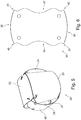
- FIG. 6 branches another schematically illustrated variant of a male part 34 according to the invention with curved and / or curved narrow side surfaces 35-38 and, for example, tapered plug-in projections 39-42.
Landscapes
- Engineering & Computer Science (AREA)
- General Engineering & Computer Science (AREA)
- Manufacturing & Machinery (AREA)
- Connector Housings Or Holding Contact Members (AREA)
- Non-Portable Lighting Devices Or Systems Thereof (AREA)
Applications Claiming Priority (1)
| Application Number | Priority Date | Filing Date | Title |
|---|---|---|---|
| DE102016103006.6A DE102016103006A1 (de) | 2016-02-22 | 2016-02-22 | Steckteil für eine 3-dimensionale Umhüllung |
Publications (2)
| Publication Number | Publication Date |
|---|---|
| EP3208532A1 true EP3208532A1 (fr) | 2017-08-23 |
| EP3208532B1 EP3208532B1 (fr) | 2020-09-09 |
Family
ID=58266355
Family Applications (1)
| Application Number | Title | Priority Date | Filing Date |
|---|---|---|---|
| EP17157427.0A Active EP3208532B1 (fr) | 2016-02-22 | 2017-02-22 | Fiche pour une enveloppe à 3 dimensions |
Country Status (2)
| Country | Link |
|---|---|
| EP (1) | EP3208532B1 (fr) |
| DE (1) | DE102016103006A1 (fr) |
Citations (6)
| Publication number | Priority date | Publication date | Assignee | Title |
|---|---|---|---|---|
| US2075259A (en) * | 1936-02-13 | 1937-03-30 | Harold A Battjes | Toy construction card |
| US3562077A (en) * | 1966-10-26 | 1971-02-09 | Raoul Raba | Component for use in making decorative structures |
| US4976652A (en) * | 1989-11-09 | 1990-12-11 | Idan Schwartz | Flat handcraft construction element with slot and opposed tabs |
| US20020078653A1 (en) * | 2000-11-28 | 2002-06-27 | Richard Jean | Card like construction element |
| WO2007001133A1 (fr) * | 2005-06-29 | 2007-01-04 | Bong-Jae Lee | Structure pour assembler un puzzle en forme de ballon de football |
| EP2873624A1 (fr) * | 2012-07-02 | 2015-05-20 | Vergés Escuín, Ricardo | Pièce laminaire pour monter des polyèdres, polyèdre et procédé de montage correspondants |
Family Cites Families (3)
| Publication number | Priority date | Publication date | Assignee | Title |
|---|---|---|---|---|
| DE19847340C2 (de) * | 1998-10-14 | 2001-09-27 | Iwers Carsten | Standleuchtenkörper und entsprechendes Herstellungsverfahren |
| DE202012009895U1 (de) * | 2012-10-17 | 2013-01-21 | Petra Wüstling | Faltbare Leuchte |
| US9784426B2 (en) * | 2014-07-29 | 2017-10-10 | Roly Joe Holder | Systems and methods for forming self-supporting three-dimensional structures |
-
2016
- 2016-02-22 DE DE102016103006.6A patent/DE102016103006A1/de not_active Withdrawn
-
2017
- 2017-02-22 EP EP17157427.0A patent/EP3208532B1/fr active Active
Patent Citations (6)
| Publication number | Priority date | Publication date | Assignee | Title |
|---|---|---|---|---|
| US2075259A (en) * | 1936-02-13 | 1937-03-30 | Harold A Battjes | Toy construction card |
| US3562077A (en) * | 1966-10-26 | 1971-02-09 | Raoul Raba | Component for use in making decorative structures |
| US4976652A (en) * | 1989-11-09 | 1990-12-11 | Idan Schwartz | Flat handcraft construction element with slot and opposed tabs |
| US20020078653A1 (en) * | 2000-11-28 | 2002-06-27 | Richard Jean | Card like construction element |
| WO2007001133A1 (fr) * | 2005-06-29 | 2007-01-04 | Bong-Jae Lee | Structure pour assembler un puzzle en forme de ballon de football |
| EP2873624A1 (fr) * | 2012-07-02 | 2015-05-20 | Vergés Escuín, Ricardo | Pièce laminaire pour monter des polyèdres, polyèdre et procédé de montage correspondants |
Also Published As
| Publication number | Publication date |
|---|---|
| DE102016103006A1 (de) | 2017-08-24 |
| EP3208532B1 (fr) | 2020-09-09 |
Similar Documents
| Publication | Publication Date | Title |
|---|---|---|
| WO2010081532A1 (fr) | Latte, en particulier latte de plancher | |
| DE102009021730A1 (de) | Verbindung von Leiterplatten | |
| EP1864705A1 (fr) | Liaison crantée et système de construction | |
| DE102015115372B4 (de) | Einrastventil | |
| DE10302138A1 (de) | Steckverbinder | |
| CH716951A8 (de) | Verbindungseinrichtung zur Ausbildung von Kastenprofilen, insbesondere für Messe- und Ladenbausysteme. | |
| EP1443251A2 (fr) | Dispositif de bride | |
| EP3208532B1 (fr) | Fiche pour une enveloppe à 3 dimensions | |
| EP3850254A1 (fr) | Traversée murale pour câbles | |
| DE102005052794B4 (de) | Halteelement zur Befestigung eines Abdeckrahmens eines Installationsgerätes | |
| DE102011055760B4 (de) | Montagefuß für eine Reihenklemme zum Befestigen an einer Tragschiene und Reihenklemme | |
| DE102004013010B3 (de) | Vorrichtung zur Aufnahme von länglichen Gegenständen | |
| DE102015003795A1 (de) | Kabeldose | |
| DE112014002199B4 (de) | Elektronische Baugruppe mit einem Kunststoffgehäuse | |
| DE102010039203A1 (de) | Steckbuchsenelement | |
| DE102012205047B4 (de) | Steckverbinderelement und Steckverbindungssystem zur Verbindung zweier Bauteile | |
| DE20019792U1 (de) | Steckverbinder-Gehäuse mit Kodiereinrichtung | |
| EP3062405B1 (fr) | Connecteur à fiches pour écrans de protection, en particulier écrans de protection pour des goulottes de montage d'appareils | |
| DE2103965C2 (de) | Bauelement,insbesondere Spielzeug- und Hochbau-element | |
| EP2251591B1 (fr) | Elément de trame pour une lampe | |
| DE202022103613U1 (de) | Installationsgerät zur Installation einer Schalteinrichtung | |
| DE29703849U1 (de) | Kabelkanalschiene für einen Eckverbinder eines Kabelkanals | |
| DE202015104355U1 (de) | Kodiererzeugnis | |
| DE2718150C2 (de) | Gitter-Nutenfeld | |
| DE202011050906U1 (de) | Wand- oder Deckenverkleidung, umfassend zumindest zwei Paneele |
Legal Events
| Date | Code | Title | Description |
|---|---|---|---|
| PUAI | Public reference made under article 153(3) epc to a published international application that has entered the european phase |
Free format text: ORIGINAL CODE: 0009012 |
|
| STAA | Information on the status of an ep patent application or granted ep patent |
Free format text: STATUS: THE APPLICATION HAS BEEN PUBLISHED |
|
| AK | Designated contracting states |
Kind code of ref document: A1 Designated state(s): AL AT BE BG CH CY CZ DE DK EE ES FI FR GB GR HR HU IE IS IT LI LT LU LV MC MK MT NL NO PL PT RO RS SE SI SK SM TR |
|
| AX | Request for extension of the european patent |
Extension state: BA ME |
|
| STAA | Information on the status of an ep patent application or granted ep patent |
Free format text: STATUS: REQUEST FOR EXAMINATION WAS MADE |
|
| 17P | Request for examination filed |
Effective date: 20180221 |
|
| RBV | Designated contracting states (corrected) |
Designated state(s): AL AT BE BG CH CY CZ DE DK EE ES FI FR GB GR HR HU IE IS IT LI LT LU LV MC MK MT NL NO PL PT RO RS SE SI SK SM TR |
|
| STAA | Information on the status of an ep patent application or granted ep patent |
Free format text: STATUS: EXAMINATION IS IN PROGRESS |
|
| 17Q | First examination report despatched |
Effective date: 20180529 |
|
| GRAP | Despatch of communication of intention to grant a patent |
Free format text: ORIGINAL CODE: EPIDOSNIGR1 |
|
| STAA | Information on the status of an ep patent application or granted ep patent |
Free format text: STATUS: GRANT OF PATENT IS INTENDED |
|
| INTG | Intention to grant announced |
Effective date: 20200401 |
|
| GRAS | Grant fee paid |
Free format text: ORIGINAL CODE: EPIDOSNIGR3 |
|
| GRAA | (expected) grant |
Free format text: ORIGINAL CODE: 0009210 |
|
| STAA | Information on the status of an ep patent application or granted ep patent |
Free format text: STATUS: THE PATENT HAS BEEN GRANTED |
|
| AK | Designated contracting states |
Kind code of ref document: B1 Designated state(s): AL AT BE BG CH CY CZ DE DK EE ES FI FR GB GR HR HU IE IS IT LI LT LU LV MC MK MT NL NO PL PT RO RS SE SI SK SM TR |
|
| REG | Reference to a national code |
Ref country code: GB Ref legal event code: FG4D Free format text: NOT ENGLISH |
|
| REG | Reference to a national code |
Ref country code: AT Ref legal event code: REF Ref document number: 1312017 Country of ref document: AT Kind code of ref document: T Effective date: 20200915 Ref country code: CH Ref legal event code: EP |
|
| REG | Reference to a national code |
Ref country code: IE Ref legal event code: FG4D Free format text: LANGUAGE OF EP DOCUMENT: GERMAN |
|
| REG | Reference to a national code |
Ref country code: DE Ref legal event code: R096 Ref document number: 502017007114 Country of ref document: DE |
|
| REG | Reference to a national code |
Ref country code: CH Ref legal event code: NV Representative=s name: KELLER SCHNEIDER PATENT- UND MARKENANWAELTE AG, CH |
|
| REG | Reference to a national code |
Ref country code: LT Ref legal event code: MG4D |
|
| PG25 | Lapsed in a contracting state [announced via postgrant information from national office to epo] |
Ref country code: FI Free format text: LAPSE BECAUSE OF FAILURE TO SUBMIT A TRANSLATION OF THE DESCRIPTION OR TO PAY THE FEE WITHIN THE PRESCRIBED TIME-LIMIT Effective date: 20200909 Ref country code: HR Free format text: LAPSE BECAUSE OF FAILURE TO SUBMIT A TRANSLATION OF THE DESCRIPTION OR TO PAY THE FEE WITHIN THE PRESCRIBED TIME-LIMIT Effective date: 20200909 Ref country code: BG Free format text: LAPSE BECAUSE OF FAILURE TO SUBMIT A TRANSLATION OF THE DESCRIPTION OR TO PAY THE FEE WITHIN THE PRESCRIBED TIME-LIMIT Effective date: 20201209 Ref country code: NO Free format text: LAPSE BECAUSE OF FAILURE TO SUBMIT A TRANSLATION OF THE DESCRIPTION OR TO PAY THE FEE WITHIN THE PRESCRIBED TIME-LIMIT Effective date: 20201209 Ref country code: SE Free format text: LAPSE BECAUSE OF FAILURE TO SUBMIT A TRANSLATION OF THE DESCRIPTION OR TO PAY THE FEE WITHIN THE PRESCRIBED TIME-LIMIT Effective date: 20200909 Ref country code: LT Free format text: LAPSE BECAUSE OF FAILURE TO SUBMIT A TRANSLATION OF THE DESCRIPTION OR TO PAY THE FEE WITHIN THE PRESCRIBED TIME-LIMIT Effective date: 20200909 Ref country code: GR Free format text: LAPSE BECAUSE OF FAILURE TO SUBMIT A TRANSLATION OF THE DESCRIPTION OR TO PAY THE FEE WITHIN THE PRESCRIBED TIME-LIMIT Effective date: 20201210 |
|
| REG | Reference to a national code |
Ref country code: NL Ref legal event code: MP Effective date: 20200909 |
|
| PG25 | Lapsed in a contracting state [announced via postgrant information from national office to epo] |
Ref country code: PL Free format text: LAPSE BECAUSE OF FAILURE TO SUBMIT A TRANSLATION OF THE DESCRIPTION OR TO PAY THE FEE WITHIN THE PRESCRIBED TIME-LIMIT Effective date: 20200909 Ref country code: LV Free format text: LAPSE BECAUSE OF FAILURE TO SUBMIT A TRANSLATION OF THE DESCRIPTION OR TO PAY THE FEE WITHIN THE PRESCRIBED TIME-LIMIT Effective date: 20200909 Ref country code: RS Free format text: LAPSE BECAUSE OF FAILURE TO SUBMIT A TRANSLATION OF THE DESCRIPTION OR TO PAY THE FEE WITHIN THE PRESCRIBED TIME-LIMIT Effective date: 20200909 |
|
| PG25 | Lapsed in a contracting state [announced via postgrant information from national office to epo] |
Ref country code: RO Free format text: LAPSE BECAUSE OF FAILURE TO SUBMIT A TRANSLATION OF THE DESCRIPTION OR TO PAY THE FEE WITHIN THE PRESCRIBED TIME-LIMIT Effective date: 20200909 Ref country code: PT Free format text: LAPSE BECAUSE OF FAILURE TO SUBMIT A TRANSLATION OF THE DESCRIPTION OR TO PAY THE FEE WITHIN THE PRESCRIBED TIME-LIMIT Effective date: 20210111 Ref country code: CZ Free format text: LAPSE BECAUSE OF FAILURE TO SUBMIT A TRANSLATION OF THE DESCRIPTION OR TO PAY THE FEE WITHIN THE PRESCRIBED TIME-LIMIT Effective date: 20200909 Ref country code: EE Free format text: LAPSE BECAUSE OF FAILURE TO SUBMIT A TRANSLATION OF THE DESCRIPTION OR TO PAY THE FEE WITHIN THE PRESCRIBED TIME-LIMIT Effective date: 20200909 Ref country code: SM Free format text: LAPSE BECAUSE OF FAILURE TO SUBMIT A TRANSLATION OF THE DESCRIPTION OR TO PAY THE FEE WITHIN THE PRESCRIBED TIME-LIMIT Effective date: 20200909 |
|
| PG25 | Lapsed in a contracting state [announced via postgrant information from national office to epo] |
Ref country code: IS Free format text: LAPSE BECAUSE OF FAILURE TO SUBMIT A TRANSLATION OF THE DESCRIPTION OR TO PAY THE FEE WITHIN THE PRESCRIBED TIME-LIMIT Effective date: 20210109 Ref country code: AL Free format text: LAPSE BECAUSE OF FAILURE TO SUBMIT A TRANSLATION OF THE DESCRIPTION OR TO PAY THE FEE WITHIN THE PRESCRIBED TIME-LIMIT Effective date: 20200909 Ref country code: ES Free format text: LAPSE BECAUSE OF FAILURE TO SUBMIT A TRANSLATION OF THE DESCRIPTION OR TO PAY THE FEE WITHIN THE PRESCRIBED TIME-LIMIT Effective date: 20200909 |
|
| REG | Reference to a national code |
Ref country code: DE Ref legal event code: R097 Ref document number: 502017007114 Country of ref document: DE |
|
| PG25 | Lapsed in a contracting state [announced via postgrant information from national office to epo] |
Ref country code: SK Free format text: LAPSE BECAUSE OF FAILURE TO SUBMIT A TRANSLATION OF THE DESCRIPTION OR TO PAY THE FEE WITHIN THE PRESCRIBED TIME-LIMIT Effective date: 20200909 |
|
| PLBE | No opposition filed within time limit |
Free format text: ORIGINAL CODE: 0009261 |
|
| STAA | Information on the status of an ep patent application or granted ep patent |
Free format text: STATUS: NO OPPOSITION FILED WITHIN TIME LIMIT |
|
| 26N | No opposition filed |
Effective date: 20210610 |
|
| PG25 | Lapsed in a contracting state [announced via postgrant information from national office to epo] |
Ref country code: DK Free format text: LAPSE BECAUSE OF FAILURE TO SUBMIT A TRANSLATION OF THE DESCRIPTION OR TO PAY THE FEE WITHIN THE PRESCRIBED TIME-LIMIT Effective date: 20200909 Ref country code: SI Free format text: LAPSE BECAUSE OF FAILURE TO SUBMIT A TRANSLATION OF THE DESCRIPTION OR TO PAY THE FEE WITHIN THE PRESCRIBED TIME-LIMIT Effective date: 20200909 |
|
| PG25 | Lapsed in a contracting state [announced via postgrant information from national office to epo] |
Ref country code: MC Free format text: LAPSE BECAUSE OF FAILURE TO SUBMIT A TRANSLATION OF THE DESCRIPTION OR TO PAY THE FEE WITHIN THE PRESCRIBED TIME-LIMIT Effective date: 20200909 |
|
| GBPC | Gb: european patent ceased through non-payment of renewal fee |
Effective date: 20210222 |
|
| REG | Reference to a national code |
Ref country code: BE Ref legal event code: MM Effective date: 20210228 |
|
| PG25 | Lapsed in a contracting state [announced via postgrant information from national office to epo] |
Ref country code: LU Free format text: LAPSE BECAUSE OF NON-PAYMENT OF DUE FEES Effective date: 20210222 Ref country code: IT Free format text: LAPSE BECAUSE OF FAILURE TO SUBMIT A TRANSLATION OF THE DESCRIPTION OR TO PAY THE FEE WITHIN THE PRESCRIBED TIME-LIMIT Effective date: 20200909 |
|
| PG25 | Lapsed in a contracting state [announced via postgrant information from national office to epo] |
Ref country code: IE Free format text: LAPSE BECAUSE OF NON-PAYMENT OF DUE FEES Effective date: 20210222 Ref country code: GB Free format text: LAPSE BECAUSE OF NON-PAYMENT OF DUE FEES Effective date: 20210222 |
|
| PG25 | Lapsed in a contracting state [announced via postgrant information from national office to epo] |
Ref country code: BE Free format text: LAPSE BECAUSE OF NON-PAYMENT OF DUE FEES Effective date: 20210228 |
|
| REG | Reference to a national code |
Ref country code: AT Ref legal event code: MM01 Ref document number: 1312017 Country of ref document: AT Kind code of ref document: T Effective date: 20220222 |
|
| PG25 | Lapsed in a contracting state [announced via postgrant information from national office to epo] |
Ref country code: AT Free format text: LAPSE BECAUSE OF NON-PAYMENT OF DUE FEES Effective date: 20220222 |
|
| PG25 | Lapsed in a contracting state [announced via postgrant information from national office to epo] |
Ref country code: HU Free format text: LAPSE BECAUSE OF FAILURE TO SUBMIT A TRANSLATION OF THE DESCRIPTION OR TO PAY THE FEE WITHIN THE PRESCRIBED TIME-LIMIT; INVALID AB INITIO Effective date: 20170222 |
|
| PG25 | Lapsed in a contracting state [announced via postgrant information from national office to epo] |
Ref country code: NL Free format text: LAPSE BECAUSE OF NON-PAYMENT OF DUE FEES Effective date: 20200923 Ref country code: CY Free format text: LAPSE BECAUSE OF FAILURE TO SUBMIT A TRANSLATION OF THE DESCRIPTION OR TO PAY THE FEE WITHIN THE PRESCRIBED TIME-LIMIT Effective date: 20200909 |
|
| PG25 | Lapsed in a contracting state [announced via postgrant information from national office to epo] |
Ref country code: MK Free format text: LAPSE BECAUSE OF FAILURE TO SUBMIT A TRANSLATION OF THE DESCRIPTION OR TO PAY THE FEE WITHIN THE PRESCRIBED TIME-LIMIT Effective date: 20200909 |
|
| PG25 | Lapsed in a contracting state [announced via postgrant information from national office to epo] |
Ref country code: TR Free format text: LAPSE BECAUSE OF FAILURE TO SUBMIT A TRANSLATION OF THE DESCRIPTION OR TO PAY THE FEE WITHIN THE PRESCRIBED TIME-LIMIT Effective date: 20200909 |
|
| PG25 | Lapsed in a contracting state [announced via postgrant information from national office to epo] |
Ref country code: MT Free format text: LAPSE BECAUSE OF FAILURE TO SUBMIT A TRANSLATION OF THE DESCRIPTION OR TO PAY THE FEE WITHIN THE PRESCRIBED TIME-LIMIT Effective date: 20200909 |
|
| REG | Reference to a national code |
Ref country code: DE Ref legal event code: R082 Ref document number: 502017007114 Country of ref document: DE Representative=s name: RAVENSPAT PATENTANWAELTE PARTNERSCHAFT MBB, DE |
|
| REG | Reference to a national code |
Ref country code: CH Ref legal event code: U11 Free format text: ST27 STATUS EVENT CODE: U-0-0-U10-U11 (AS PROVIDED BY THE NATIONAL OFFICE) Effective date: 20260301 |
|
| PGFP | Annual fee paid to national office [announced via postgrant information from national office to epo] |
Ref country code: DE Payment date: 20260217 Year of fee payment: 10 |
|
| PGFP | Annual fee paid to national office [announced via postgrant information from national office to epo] |
Ref country code: FR Payment date: 20260223 Year of fee payment: 10 |
|
| PGFP | Annual fee paid to national office [announced via postgrant information from national office to epo] |
Ref country code: CH Payment date: 20260301 Year of fee payment: 10 |