EP3208546A1 - Dispositif de fixation d'un élément de commande d'un appareil ménager, partie de boîtier pour un appareil ménager et appareil ménager - Google Patents
Dispositif de fixation d'un élément de commande d'un appareil ménager, partie de boîtier pour un appareil ménager et appareil ménager Download PDFInfo
- Publication number
- EP3208546A1 EP3208546A1 EP17150952.4A EP17150952A EP3208546A1 EP 3208546 A1 EP3208546 A1 EP 3208546A1 EP 17150952 A EP17150952 A EP 17150952A EP 3208546 A1 EP3208546 A1 EP 3208546A1
- Authority
- EP
- European Patent Office
- Prior art keywords
- control panel
- fastening device
- clamping
- housing part
- profile element
- Prior art date
- Legal status (The legal status is an assumption and is not a legal conclusion. Google has not performed a legal analysis and makes no representation as to the accuracy of the status listed.)
- Withdrawn
Links
- 230000007704 transition Effects 0.000 claims description 4
- 239000002184 metal Substances 0.000 description 5
- 230000001419 dependent effect Effects 0.000 description 3
- 230000008878 coupling Effects 0.000 description 2
- 238000010168 coupling process Methods 0.000 description 2
- 238000005859 coupling reaction Methods 0.000 description 2
- 238000011161 development Methods 0.000 description 1
- 230000018109 developmental process Effects 0.000 description 1
- 238000009434 installation Methods 0.000 description 1
- 239000000463 material Substances 0.000 description 1
- 238000000034 method Methods 0.000 description 1
Images


Classifications
-
- F—MECHANICAL ENGINEERING; LIGHTING; HEATING; WEAPONS; BLASTING
- F24—HEATING; RANGES; VENTILATING
- F24C—DOMESTIC STOVES OR RANGES ; DETAILS OF DOMESTIC STOVES OR RANGES, OF GENERAL APPLICATION
- F24C15/00—Details
- F24C15/20—Removing cooking fumes
- F24C15/2021—Arrangement or mounting of control or safety systems
-
- F—MECHANICAL ENGINEERING; LIGHTING; HEATING; WEAPONS; BLASTING
- F16—ENGINEERING ELEMENTS AND UNITS; GENERAL MEASURES FOR PRODUCING AND MAINTAINING EFFECTIVE FUNCTIONING OF MACHINES OR INSTALLATIONS; THERMAL INSULATION IN GENERAL
- F16B—DEVICES FOR FASTENING OR SECURING CONSTRUCTIONAL ELEMENTS OR MACHINE PARTS TOGETHER, e.g. NAILS, BOLTS, CIRCLIPS, CLAMPS, CLIPS OR WEDGES; JOINTS OR JOINTING
- F16B21/00—Means for preventing relative axial movement of a pin, spigot, shaft or the like and a member surrounding it; Stud-and-socket releasable fastenings
- F16B21/09—Releasable fastening devices with a stud engaging a keyhole slot
-
- F—MECHANICAL ENGINEERING; LIGHTING; HEATING; WEAPONS; BLASTING
- F16—ENGINEERING ELEMENTS AND UNITS; GENERAL MEASURES FOR PRODUCING AND MAINTAINING EFFECTIVE FUNCTIONING OF MACHINES OR INSTALLATIONS; THERMAL INSULATION IN GENERAL
- F16B—DEVICES FOR FASTENING OR SECURING CONSTRUCTIONAL ELEMENTS OR MACHINE PARTS TOGETHER, e.g. NAILS, BOLTS, CIRCLIPS, CLAMPS, CLIPS OR WEDGES; JOINTS OR JOINTING
- F16B5/00—Joining sheets or plates, e.g. panels, to one another or to strips or bars parallel to them
- F16B5/06—Joining sheets or plates, e.g. panels, to one another or to strips or bars parallel to them by means of clamps or clips
- F16B5/0607—Joining sheets or plates, e.g. panels, to one another or to strips or bars parallel to them by means of clamps or clips joining sheets or plates to each other
- F16B5/0621—Joining sheets or plates, e.g. panels, to one another or to strips or bars parallel to them by means of clamps or clips joining sheets or plates to each other in parallel relationship
- F16B5/0635—Joining sheets or plates, e.g. panels, to one another or to strips or bars parallel to them by means of clamps or clips joining sheets or plates to each other in parallel relationship fastened over the edges of the sheets or plates
Definitions
- the invention relates to a fastening device for fastening a control panel for a household appliance, a housing part for a household appliance and a household appliance.
- the object of the invention is to provide an improved fastening device for fastening a control unit for a domestic appliance, an improved housing part for a domestic appliance and an improved domestic appliance.
- the achievable with the present invention consist in addition to a realization of a tool-free and assembly and disassembly of controls on household appliances in an enabling a quick installation of controls for household appliances.
- a fastening by screws, nuts or the like in particular no tool for assembly and disassembly is required.
- a secure attachment for example, regardless of a user-dependent torque or the like is possible.
- a placement and mounting of control panels both in the assembly and in the case of customer service can be simplified.
- a stable and reliable assembly and disassembly can thus be done without tools.
- the assembly can be easily and quickly made possible regardless of torques, sheet thickness or other application-dependent or user-dependent influences.
- the household appliance may be an extractor hood or other household appliance.
- the control panel may be at least partially received in the control panel section in a state of the control panel attached to the housing member.
- the at least one clamping bracket and the at least one clamping profile element can be shaped so as to be coupled to one another and detachable from one another along the plane of extension by a translation relative to one another.
- Such an embodiment has the advantage that a safe and quick assembly and disassembly of the control unit is made possible by a simple movement sequence when decoupling the at least one clamping bracket and the at least one clamping profile element.
- the at least one clamping profile element can be formed to be coupled by a translation along the plane of extension with the control panel cutout and detachable from the control panel section.
- the at least one clamping profile element and the at least one clamping strap can be shaped in order to latch into one another.
- Such an embodiment offers the advantage that a stability of the mechanical coupling between the at least one clamping profile element and the at least one clamping bracket can be increased.
- the at least one clamping profile element and additionally or alternatively the at least one clamping strap can be formed undercut, at least in one section.
- the at least one clamping profile element and additionally or alternatively the at least one clamping bracket can have at least one partial section in which an undercut is formed.
- the at least one clamping profile element and additionally or alternatively the at least one clamping strap in the at least one partial section may or may have a collar, a rail or the like.
- the at least one clamping strap may be formed in order to at least partially surround the operating part.
- the at least one clamping strap can have a U-shaped sectional profile.
- the fastening device may comprise two clamping profile elements and two clamping brackets.
- a first clamping strap can be assigned to a first clamping profile element.
- a second clamp can be assigned to a second clamping profile element.
- control panel cutout may be formed as a slot, an elongated slot or the like.
- control panel can have step-shaped transition sections between the end sections and the central section.
- each long side of the control panel section can have, for example, two kinks or rounded kinks, each kink having a right angle or an obtuse angle.
- an embodiment of the above-mentioned fixing device and an embodiment of the above-mentioned housing part can be advantageously used or used to fix the operating part to the housing part.
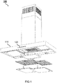
- FIG. 1 shows a household appliance 100 according to an embodiment of the invention, for example in a perspective exploded parts illustration.
- the household appliance 100 this is merely an example of an extractor hood.
- filters and filter covers of the household appliance 100 are shown separated from a body of the household appliance 100.
- the household appliance 100 has a housing part 110. Furthermore, the household appliance 100 has a control unit 120.
- the operating part 120 is fastened by means of a fastening device in a region of a control section of the housing part.
- the housing part 110, the control panel cutout, the operating part 120 and the fastening device will be described below with reference to FIGS FIGS. 2 to 9 explained in more detail.
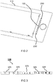
- FIG. 2 shows a housing part 110 according to an embodiment of the invention with a fixed control panel 120 for a household appliance.
- the housing part 110 is the housing part FIG. 1 or a similar housing part.
- the control panel 120 is the control panel FIG. 1 or a similar control panel. It shows FIG. 2 the housing part 110 and the operating part 120 from a front side.
- the operating part 120 is fastened to the housing part 110 by means of a fastening device.
- the housing part 110 is designed to allow attachment of the operating part 120 to the housing part 110.
- the control unit 120 is fastened to the housing part 110 in the region of the control panel cutout.
- FIG. 2 From the fastening device are in FIG. 2 For reasons of presentation, only partial sections of, by way of example, two clamping profile elements 230 are shown.
- the operating part 120 is arranged between the clamping profile elements 230 in the operating part cutout of the housing part 110.
- FIG. 3 shows the operating part 120 FIG. 1 respectively.
- the control panel 120 may alternatively be a similar control panel 120.
- the operating part 120 has a plurality of keys 325.
- the keypad 120 has, by way of example only, five keys 325.
- laterally left and right next to the keys 325 trim strips are provided, whose appearance is similar or identical to the keys 325.
- the trim strips not shown here serve the cover of in FIG. 5 shown end portions 552 of the control panel cutout 550th
- FIG. 4 shows a housing part 110 according to an embodiment of the invention with a fixed control panel 120 for a household appliance.
- the housing part 110 is the housing part FIG. 1 respectively.
- the control panel 120 is the control panel FIG. 1 respectively.
- FIG. 4 shows FIG. 4 the housing part 110 and the control unit 120 from FIG. 2 from a backside.
- FIG. 4 shows FIG. 4 Furthermore, the fastening device 400, by means of which the control unit 120 is attached to the housing part 110.
- the fastening device 400 is designed to fasten the operating part 120 to the housing part 110.
- the fastening device 400 has two clamping profile elements 230 and two clamping bracket 440.
- the clamping profile elements 230 are coupled to the housing part 110.
- a clamping bracket 440 is coupled to a respective clamping profile element 230.
- a first clamping bracket 440 is associated with a first clamping profile element 230
- a second clamping bracket 440 is associated with a second clamping profile element 230.
- each clamping bracket 440 is formed to engage around the operating part 120 at least partially or at least in a partial section.
- FIG. 5 shows a control panel cutout 550 in a housing part according to an embodiment of the invention.
- the control panel cutout 550 is in this case in the housing part FIG. 1 . FIG. 2 respectively. FIG. 4 formed.
- the housing part is, for example, a metal sheet, wherein the control panel cutout 550 represents a sheet metal cutout.
- the control panel section 550 is formed or formed to at least a portion of the control panel of the FIGS. 1 to 4 or a similar keypad.
- An extension plane of the control panel section 550 corresponds, for example, to a plane of the drawing of FIG FIG. 5 ,
- the control panel cutout 550 is elongated.
- the operation panel cutout 550 has end portions 552 abutting the both ends of the operation portion 550 and a center portion 554 between the end portions 552.
- the control panel cutout 550 has a first width in the end sections 552 and has a second width in the middle section 554 which is greater than the first width.
- the control panel cutout 550 here has step-shaped transition sections between the end sections 552 and the central section 554.
- FIG. 6 shows a fastening device 400 according to an embodiment of the invention in a partially coupled state in a control panel cutout 550 of a housing part 110.
- the fastening device 400 is the fastening device FIG. 4 or a similar fastening device.
- the housing part 110 and the control panel cutout 550 correspond to the housing part and the control panel cutout from the FIGS. 1 to 5 or similar.
- the fastening device 400 is in FIG. 6 shown in a sectional view along a longitudinal axis of the control panel section 550.
- the clamping profile element 230 is formed to be positively coupled to the control panel section 550. Further, the clamping profile element 230 is formed to fix the operating part with respect to a movement in an extension plane of the control panel section 550.
- the clamping bracket 440 is formed to be positively coupled to the clamping profile element 230. Also, the clamp 440 is formed to fix the actuator with respect to a movement transverse to the plane of extension of the control panel section 550.
- the clamping profile element 230 is shown in FIG FIG. 6 with the housing part 110 and the control panel section 550 coupled, wherein the clamping profile element 230 and the clamping bracket 440 are partially coupled together.
- the clamping profile element 230 is held in the operating part cutout 550 by a positive connection with the housing part 110 or sheet metal. A further fixation of the clamping profile element 230 results when used in the control panel section 550 keypad.
- the clamping bracket 440 is held according to the embodiment of the invention shown here by an undercut or an undercut with the clamping profile element 230 and additionally or alternatively or optionally by a latching with the clamping profile element 230.
- the clamping profile element 230 and / or the clamping bracket 440 are or are formed undercut at least in one section.
- the clamping profile element 230 and the clamping bracket 440 are formed to lock into one another.
- the clamping bracket 440 is designed to press the operating part against the housing part 110 into the operating part cutout 550.
- the clamping profile element 230 is formed to be coupled by a translation along the plane of extension of the control panel section 550 with the control panel section 550 and detachable from the control panel section 550.
- the clamping bracket 440 and the clamping profile element 230 are formed so as to be coupled to each other by a translation relative to each other along the plane of extension of the control panel section 550 and detachable from each other.
- a movement of the clamping profile element 230 is blocked by the housing part 110 or the control panel cutout 550 in directions transverse to the plane of extent and in the plane of extent except for a dismounting direction for decoupling the clamping profile element 230.
- a movement of the clamping profile element 230 in the dismounting direction is locked by the control unit in a mounted state. Further, movement of the clamp 440 is locked in all directions and all axes except for the disassembly direction by the clamping profile element 230.
- a movement of the clamping bracket 440 in the dismounting direction is blocked, for example, by the latch or detent.
- FIG. 7 shows the fastening device 400 from FIG. 6 in a coupled state.
- the fastening device for 100 and the control panel cutout 550 are shown in a plan view.
- the clamping profile element 230 and the clamping bracket 440 are in FIG. 7 completely coupled with each other.
- the clamping profile element 230 and thus also the clamping bracket 440 are arranged in the region of an end section of the control panel section 550.
- FIG. 8 shows a fastening device 400 according to an embodiment of the invention and an attached to a housing part 110 operating part 120.
- the fastening device 400 is the fastening device FIG. 4 . FIG. 6 respectively. FIG. 7 or a similar fastening device.
- the housing part 110 and the operating part 120 correspond to the housing part and the operating part of the FIGS. 1 to 7 or similar.
- the fastening device 400 is in FIG. 8 shown in a sectional view transverse to a longitudinal axis or along a transverse axis of the control panel detail.
- the operating part 120 is fastened to the housing part 110 by means of the fastening device 400.
- the operating part 120 is clamped between the clamping profile element 230 and the clamping bracket 440.
- the clamp 440 is formed to engage around the control panel 120 at least partially.
- the clamping bracket 440 is according to the in FIG. 8 illustrated embodiment of the invention further formed to engage around at least a portion of the clamping profile element 230.
- FIG. 9 shows the fastening device 400 from FIG. 8 and attached to the housing part 110 control panel 120.
- the fastening device 400 is shown in a sectional view transverse to a longitudinal axis or along a transverse axis of the control panel section, wherein compared with a sectional plane of FIG. 8 a cutting plane in FIG. 9 along the longitudinal axis of the control panel section is further shifted towards the end portion of the control panel section.
- the operating part 120 is arranged or positioned between two clamping profile elements 230 or pushbutton shutters 230 inserted terminally in the operating part cutout 550 or sheet metal cutout. Subsequently, the operating part 120 is comprised by the clamping brackets 440 or brackets made of a plastic material. The control unit 120 is then pressed with the clamping brackets 440 in the direction of the housing part 110 or sheet metal. When the operating part 120 is positioned in the operating part cutout 550, the clamping straps 440 are pushed laterally onto the clamping profile elements 230 in the direction of the end sections 552 of the operating section cutout 550. The control panel 120 is thus firmly positioned in the control panel section 550. Dismantling takes place in reverse order.
- the clamping profile elements 230 are first inserted into the middle section 554 or the wide area of the control panel section 550. Subsequently, the clamping profile elements 230 are displaced until the clamping profile elements 230 engage with the end sections 552 and the narrow sections of the control panel section 550 Are engaged. Subsequently, the operating part 120 is inserted into the operating part cutout 550. Then the clamps 440 are slipped over the control panel 120. Finally, the clamps 440 are moved to the clamping profile elements 230, wherein at least one undercut and optionally a latching can be provided.
Landscapes
- Engineering & Computer Science (AREA)
- Chemical & Material Sciences (AREA)
- Combustion & Propulsion (AREA)
- Mechanical Engineering (AREA)
- General Engineering & Computer Science (AREA)
- Casings For Electric Apparatus (AREA)
Applications Claiming Priority (1)
| Application Number | Priority Date | Filing Date | Title |
|---|---|---|---|
| DE102016102674.3A DE102016102674B3 (de) | 2016-02-16 | 2016-02-16 | Befestigungsvorrichtung zum Befestigen eines Bedienteils für ein Haushaltgerät und Haushaltgerät |
Publications (1)
| Publication Number | Publication Date |
|---|---|
| EP3208546A1 true EP3208546A1 (fr) | 2017-08-23 |
Family
ID=57630308
Family Applications (1)
| Application Number | Title | Priority Date | Filing Date |
|---|---|---|---|
| EP17150952.4A Withdrawn EP3208546A1 (fr) | 2016-02-16 | 2017-01-11 | Dispositif de fixation d'un élément de commande d'un appareil ménager, partie de boîtier pour un appareil ménager et appareil ménager |
Country Status (2)
| Country | Link |
|---|---|
| EP (1) | EP3208546A1 (fr) |
| DE (1) | DE102016102674B3 (fr) |
Citations (5)
| Publication number | Priority date | Publication date | Assignee | Title |
|---|---|---|---|---|
| US3363290A (en) * | 1964-10-15 | 1968-01-16 | Raymond A | Cable clip with non-tangling features |
| DE8532347U1 (de) * | 1985-11-15 | 1987-03-19 | Robert Bosch Gmbh, 7000 Stuttgart | Vorrichtung zum Befestigen plattenförmiger Elemente |
| FR2673250A1 (fr) * | 1991-02-26 | 1992-08-28 | Otis Elevator Co | Dispositif de fixation invisible d'une platine sur une plaque d'applique. |
| FR2750177A1 (fr) * | 1996-06-25 | 1997-12-26 | Peugeot | Dispositif de verrouillage et d'agrafage d'une piece sur une autre et vehicule automobile equipe de ce dispositif |
| DE10259748A1 (de) * | 2002-12-19 | 2004-07-08 | BSH Bosch und Siemens Hausgeräte GmbH | Dunstabzugshaube und Eingabemodul |
Family Cites Families (2)
| Publication number | Priority date | Publication date | Assignee | Title |
|---|---|---|---|---|
| DE19950829B4 (de) * | 1999-10-21 | 2008-09-11 | BSH Bosch und Siemens Hausgeräte GmbH | Befestigungsvorrichtung in einem Haushaltsgerät |
| DE102014100414B4 (de) * | 2014-01-15 | 2020-10-15 | Miele & Cie. Kg | Dunstabzugshaubeneinrichtung |
-
2016
- 2016-02-16 DE DE102016102674.3A patent/DE102016102674B3/de active Active
-
2017
- 2017-01-11 EP EP17150952.4A patent/EP3208546A1/fr not_active Withdrawn
Patent Citations (5)
| Publication number | Priority date | Publication date | Assignee | Title |
|---|---|---|---|---|
| US3363290A (en) * | 1964-10-15 | 1968-01-16 | Raymond A | Cable clip with non-tangling features |
| DE8532347U1 (de) * | 1985-11-15 | 1987-03-19 | Robert Bosch Gmbh, 7000 Stuttgart | Vorrichtung zum Befestigen plattenförmiger Elemente |
| FR2673250A1 (fr) * | 1991-02-26 | 1992-08-28 | Otis Elevator Co | Dispositif de fixation invisible d'une platine sur une plaque d'applique. |
| FR2750177A1 (fr) * | 1996-06-25 | 1997-12-26 | Peugeot | Dispositif de verrouillage et d'agrafage d'une piece sur une autre et vehicule automobile equipe de ce dispositif |
| DE10259748A1 (de) * | 2002-12-19 | 2004-07-08 | BSH Bosch und Siemens Hausgeräte GmbH | Dunstabzugshaube und Eingabemodul |
Also Published As
| Publication number | Publication date |
|---|---|
| DE102016102674B3 (de) | 2017-01-19 |
Similar Documents
| Publication | Publication Date | Title |
|---|---|---|
| EP2443003B1 (fr) | Ensemble de connexion | |
| EP0135845B1 (fr) | Moyens de montage d'un appareil pourvu de deux brides successives de support | |
| EP1158185A2 (fr) | Elément de fixation rapide | |
| DE20010037U1 (de) | Schnellbefestigungselement | |
| EP3050413B1 (fr) | Dispositif de ventilation | |
| EP3026350B1 (fr) | Hotte aspirante dotée d'un composant | |
| EP2012390B1 (fr) | Pince de mise à la terre destinée à l'équilibrage du potentiel de canaux de câblage | |
| EP2199687A2 (fr) | Unité de commande pour un appareil ménager et appareil ménager | |
| DE102016102674B3 (de) | Befestigungsvorrichtung zum Befestigen eines Bedienteils für ein Haushaltgerät und Haushaltgerät | |
| DE102020125243B3 (de) | Spannverschluss zur werkzeuglosen Montage und System zur werkzeuglosen Montage des Spannverschlusses | |
| DE202012102981U1 (de) | Vorrichtung zum Festlegen einer Rohreinheit | |
| EP2273638A2 (fr) | Pince pour canaux de câble destinée à masquer des bords de coupe | |
| EP2292861A2 (fr) | Fenêtre de toit d'habitation et procédé de fixation d'une tôle de recouvrement | |
| EP2199509B1 (fr) | Bloc d'armature pour un système d'armature de tige motrice | |
| DE102009058815B4 (de) | Haltevorrichtung für Anbauteile von Fahrzeugen | |
| EP2145135B1 (fr) | Parois latérales d'un logement pour hotte aspirante, logement pour hotte aspirante et hotte aspirante correspondante | |
| EP0974791B1 (fr) | Revêtement pour radiateur à plaques avec élément d'actionnement externe | |
| DE102019114926A1 (de) | Gurtaufrollervorrichtung für ein Kraftfahrzeug | |
| DE102017111903B4 (de) | Klemmeinheit zum Festklemmen einer Glasscheibe für eine Dunstabzugshaube, Befestigungsvorrichtung zum Befestigen zumindest einer Glasscheibe an einer Dunstabzugshaube und Dunstabzugshaube | |
| EP0109555A2 (fr) | Armoire de commutation électrique | |
| EP3967932B1 (fr) | Plaque de cuisson, comprenant une plaque de recouvrement pourvu d'au moins une zone de cuisson et d'un fond de plaque de cuisson | |
| WO2020064284A1 (fr) | Moyen de retenue pour appareil culinaire et appareil culinaire | |
| DE102014206280B4 (de) | Tür für ein Haushaltsgerät mit einer zweidimensional wirkenden Halte- und Positioniervorrichtung für eine Türscheibe sowie Haushaltsgerät mit einer Tür und Verfahren zur Montage einer Tür | |
| EP1528648B1 (fr) | Dispositif pour fixer un appareil de refroidissement sur une armoire électrique | |
| EP1593786B1 (fr) | Dispositif de fixation pour éléments dans plaques de travail |
Legal Events
| Date | Code | Title | Description |
|---|---|---|---|
| PUAI | Public reference made under article 153(3) epc to a published international application that has entered the european phase |
Free format text: ORIGINAL CODE: 0009012 |
|
| AK | Designated contracting states |
Kind code of ref document: A1 Designated state(s): AL AT BE BG CH CY CZ DE DK EE ES FI FR GB GR HR HU IE IS IT LI LT LU LV MC MK MT NL NO PL PT RO RS SE SI SK SM TR |
|
| AX | Request for extension of the european patent |
Extension state: BA ME |
|
| STAA | Information on the status of an ep patent application or granted ep patent |
Free format text: STATUS: THE APPLICATION IS DEEMED TO BE WITHDRAWN |
|
| 18D | Application deemed to be withdrawn |
Effective date: 20180224 |