EP3209470B1 - Dispositif de découpe au jet d'eau - Google Patents
Dispositif de découpe au jet d'eau Download PDFInfo
- Publication number
- EP3209470B1 EP3209470B1 EP15771144.1A EP15771144A EP3209470B1 EP 3209470 B1 EP3209470 B1 EP 3209470B1 EP 15771144 A EP15771144 A EP 15771144A EP 3209470 B1 EP3209470 B1 EP 3209470B1
- Authority
- EP
- European Patent Office
- Prior art keywords
- water jet
- cutting device
- jet cutting
- cutting table
- manner
- Prior art date
- Legal status (The legal status is an assumption and is not a legal conclusion. Google has not performed a legal analysis and makes no representation as to the accuracy of the status listed.)
- Not-in-force
Links
- 238000005520 cutting process Methods 0.000 title claims description 140
- XLYOFNOQVPJJNP-UHFFFAOYSA-N water Substances O XLYOFNOQVPJJNP-UHFFFAOYSA-N 0.000 title claims description 131
- 239000000463 material Substances 0.000 claims description 10
- 238000011109 contamination Methods 0.000 description 5
- 239000000123 paper Substances 0.000 description 5
- 238000000926 separation method Methods 0.000 description 5
- 239000000835 fiber Substances 0.000 description 3
- 238000004519 manufacturing process Methods 0.000 description 3
- 150000001875 compounds Chemical class 0.000 description 2
- 238000009434 installation Methods 0.000 description 2
- 238000005422 blasting Methods 0.000 description 1
- 230000001066 destructive effect Effects 0.000 description 1
- 230000012447 hatching Effects 0.000 description 1
- 238000003780 insertion Methods 0.000 description 1
- 230000037431 insertion Effects 0.000 description 1
- 239000002245 particle Substances 0.000 description 1
- 238000012958 reprocessing Methods 0.000 description 1
- 239000007921 spray Substances 0.000 description 1
- 239000000126 substance Substances 0.000 description 1
Images
Classifications
-
- B—PERFORMING OPERATIONS; TRANSPORTING
- B26—HAND CUTTING TOOLS; CUTTING; SEVERING
- B26F—PERFORATING; PUNCHING; CUTTING-OUT; STAMPING-OUT; SEVERING BY MEANS OTHER THAN CUTTING
- B26F3/00—Severing by means other than cutting; Apparatus therefor
- B26F3/004—Severing by means other than cutting; Apparatus therefor by means of a fluid jet
-
- B—PERFORMING OPERATIONS; TRANSPORTING
- B26—HAND CUTTING TOOLS; CUTTING; SEVERING
- B26F—PERFORATING; PUNCHING; CUTTING-OUT; STAMPING-OUT; SEVERING BY MEANS OTHER THAN CUTTING
- B26F3/00—Severing by means other than cutting; Apparatus therefor
- B26F3/004—Severing by means other than cutting; Apparatus therefor by means of a fluid jet
- B26F3/008—Energy dissipating devices therefor, e.g. catchers; Supporting beds therefor
Definitions
- the invention relates to a water jet cutting device for separating a strip from a running paper, board, tissue or another fibrous web, preferably a machine for producing and / or finishing the same, in particular according to claim 1.
- Such separation devices have been in use for a long time.
- a water jet is generated, which separates the fibrous web.
- a water jet collecting device is provided, which is usually associated with a cutting table. On the cutting table to be separated and moved past this fibrous web is supported. For safety reasons, but also to protect against contamination, the water jet is thereby, after he has severed the fibrous web, taken up by the water jet collecting device.
- the cutting table has for this purpose a collecting opening for the water jet. The latter, viewed in the direction of the application of the water after it has severed the fibrous web, passes through the collecting opening. The now remaining energy of the water jet is absorbed by the water jet catcher. The latter also serves to catch the water of the water jet and supply it to a corresponding device for its reprocessing.
- the collecting openings of the water jet collecting device are chosen to be relatively large, which, however, brings problems with regard to a sufficient support of the fibrous web in the cutting area and thus damage to the web edge.
- the relatively large collecting openings require even relatively large cutting tables. A removal and installation of such a relatively large cutting table is connected in case of wear with relatively great effort. Often is for the installation and removal of special tools necessary. Since such a change of the cutting table is possible only at a standstill of an aforementioned machine, this is reflected in comparatively high downtime and costs.
- DE 10 2005 018769 A1 describes a water jet cutting device for separating a strip from a moving fibrous web with the features of the preamble of claim 1.
- the present invention relates to the aforementioned generic objects.
- the present invention has for its object to provide a water jet cutting device of the type mentioned, with which the aforementioned problems can be eliminated in the simplest and most reliable manner.
- Distance in the sense of the invention may mean the smallest distance between the water jet (or its lateral surface) and (the lateral surface) of the boundary of the collecting opening. It can be measured in the plane parallel to the cutting table or the fibrous web which can be moved over it or a plane running parallel thereto. It can - in this level - preferably be on all sides of the water jet a maximum of 10 mm.
- the distance can also be described as follows:
- a theoretical impact surface of the water jet on the blasting table When the water jet is moved relative to the jet table, this incident surface is formed by all superimposed projections of the water jet along all positions of the water jet in the cutting direction and / or the cutting path traveled by the water jet.
- said incident surface is always concentric with the surface of the boundary of the collecting opening (hereinafter Aufffang Structure called) is formed. This again seen in the above plan view.
- Concentric Aufffang Structure and impact surface are when whose axes of symmetry coincide, but the surfaces are not the same surface, but the boundary contours are different in size.
- the above-mentioned distance in this case is the distance that form the two boundary contours to each other in the above plan view, Favor to all sides. It could also be said that the said distance corresponds to the gap between the water jet and the collecting opening.
- the small expansion of the collecting opening compared to the expansion of the water jet brings an improved support of the fibrous web during cutting. Because the fibrous web is better supported in the cutting area. Damage to the edge of the web is thereby minimized. Overall, then a clean cut of the fibrous web or the strip to be separated to be achieved.
- the collecting opening of the cutting table can also be produced by the water jet cutting device, more precisely by the water jet itself. In other words, this means that the collecting opening is still closed before the first impact of the water jet.
- the material thickness of the water jet collecting device should be so small around the collecting opening and / or the material of the water jet collecting device around the collecting opening be such that it - preferably in the intended Operation of the water jet cutting device - can be severed by the water jet.
- the water jet cutting device is set up in such a way that, at least in the short term, it is capable of severing both the fibrous web and being able to produce the collecting opening in the cutting table.
- the water jet cutting device could be configured such that the pressure of the water jet for the first time creation of the collecting opening in the cutting table at least briefly above the cutting pressure to a separation pressure could be raised. The material or the thickness of the cutting table could then be selected such that it would be severable above the cutting pressure to separation pressure by means of the water jet to create the collecting opening.
- the water jet cutting device could be associated with a pressure source which could be connected to the nozzle in a flow-conducting manner by means of a pressure line.
- a pressure adjusting valve could be provided by means of which the pressure of the nozzle supplied water, so the pressure of the water jet would be adjustable.
- the pressure could be raised by the pressure adjusting valve for a short time on the separation pressure to create the collecting opening in the cutting table - especially outside the intended operation of the water jet cutting device. After creating the collection opening in the cutting table, the pressure could be reset to cutting pressure.
- the catching hole is produced by the same for the first time.
- This first-time production of the collecting opening has the advantage that no close tolerances with regard to the spacing of the nozzle or of the water jet emerging therefrom must be maintained to an already existing collecting opening in the cutting table.
- the present invention relates to a corresponding method for producing a collecting opening in such a water jet cutting device with the steps just described.
- the water jet cutting device in addition to the pressure source, could also be assigned a treatment device by means of which the water collected by the water jet collecting device could be cleaned by the fibers of the fibrous web entrained therein.
- the removable plate In normal use, the removable plate is inserted into the cutting table and the detachable connection is closed, so that the cutting plate is held securely or captive in the cutting table.
- holding means are preferably understood to be functioning, releasable connections according to the mode of action of the force and / or form fit, such as e.g. Clamping, sliding, snap connections. But bolt or screw connections or fits fall under this.
- Locking means such means are understood by means of which the retaining means are secured against unintentional release of the connection in normal operation. Locking means are therefore arranged such that they cause a bias or biasing force on the retaining means in the closing direction - ie opposite to an opposite opening direction - the releasable connection.
- An example of this are springs which clamp the holding means against each other (in the closing direction), e.g. the at least one projection does not come out (in the opening direction) from the at least one recess.
- the water jet cutting device can be set up such that the force which is necessary to release the detachable connection and / or close, is dimensioned such that this force can still be applied by hand.
- coplanar means that two or more surfaces (or upper sides) are arranged in space relative to one another (permanently), that they coincide or are flush with one another.
- the collecting opening is formed by a separate, exchangeable removable plate of the cutting table.
- the removable disk can be exchanged so quickly on the one hand in wear and on the other hand, especially adapted to the requirements of their use in particular with regard to wear, susceptibility to contamination and size of the collecting opening.
- the symmetrical outer contour may be axially symmetrical about the longitudinal axis and / or transverse axis of the removable disk.
- longitudinal axis and / or transverse axis the respective central axis is meant.
- the longitudinal axis describes the direction of the spatial length
- the transverse axis the direction of the spatial width of the removable plate.
- the replacement plate may be arranged in the cutting table such that its longitudinal or transverse axis runs parallel to the running direction of the fibrous web or the cutting direction.
- the cutting table may have a length or the width in the range between 50 and 200 mm and a thickness between 1 and 30 mm.
- the removable disk may be smaller in length and width than the cutting table. However, it can also have a thickness between 1 and 30 mm.
- the new top is now formed by the actual back.
- the replacement plate in the region of the collecting opening comprises an insert made of a wear-resistant and contamination-resistant material.
- This may itself be releasably connectable to the removable plate, e.g. be held in force, form and / or cohesively in this. Because if the use contaminates or wears, usually only this, but not the removable plate must be replaced.
- the distance between the nozzle and the water jet collecting device or the cutting table could be less than 10 mm.
- the smallest distance could be meant, which results between an outer, for example, the water jet catcher or the cutting table side facing the nozzle and a corresponding, the nozzle facing side of the water jet collecting device and the cutting table.
- the longitudinal axis of the nozzle is ideally parallel to the z axis or coincides with this.
- the distance would then be the (smallest) distance measured in the z-axis direction between a side of the nozzle facing the water jet catching device or the cutting table and the corresponding side of the water jet catching device or the cutting table facing the nozzle. If the longitudinal axis of the nozzle is at an angle to the z-axis, the distance could be measured along an extension of the longitudinal axis of the nozzle.
- the side of the nozzle facing the water jet collecting device or the cutting table may be that side of the nozzle which delimits or forms a nozzle outlet for the water jet into the environment.
- the small distance of less than 10 mm also has the advantage that on the one hand the quality of the cut and on the other hand the risk of accidents due to the small distances are low. In the latter case, the likelihood that the operator places his fingers there is reduced.
- the invention also relates to an aforementioned machine for producing and / or finishing a moving fibrous web, such as paper, cardboard, tissue or another with a water jet cutting device according to the invention.
- the invention also relates to a use of a water jet cutting device according to the invention in such a machine.
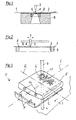
- a strip such as edge strips of a fibrous web 1.
- the edge strip can be separated parallel to the edge of the fibrous web 1 continuously from this. It can be removed to produce clean web edges, but also be required for the transfer of the fibrous web 1.
- the fibrous web 1 here in the form of a running Paper web within a paper machine, for example, at a speed between 200 and 2,500 m / min on the water jet cutting device in the direction (indicated by the arrow) along.
- the fibrous web 1 is supported at least in sections directly on a cutting table 2.
- the water jet cutting device in each case has at least one nozzle 3, which directs a water jet 4 onto the fibrous web 1 for its separation into an edge strip.
- the nozzle 3 can be connected in a flow-conducting manner to a pressure source (not shown), which may be associated with the water jet cutting device, via a pressure line.
- the water jet 4 is received on the side of the fibrous web 1 opposite the nozzle 3 by a water-jet collecting device 5.
- the cutting table 2 may be associated with the water jet collecting device 5 or, as shown, are formed directly from this. Seen in the direction of the application of the water jet, the water jet 4 initially strikes the fibrous web 1 and then passes through a collecting opening 6 in the cutting table 2 into the interior of the water jet collecting device 5.
- the water jet cutting device of FIG. 1 is designed such that nozzle 3 and water jet collecting device 5 and cutting table 2 are stationary to each other, so do not move relative to each other.
- the illustration shows the water jet cutting device in side view, so that the fibrous web 1 moves from left to right past the water jet cutting device.
- the water jet cutting device could then be set up such that water jet collecting device 5 and cutting table 2 move together relative to the fibrous web 2 in order to be able to set a predetermined width of the edge strip to be separated.
- Such a movement can in the cutting direction, for example perpendicular to the direction of the fibrous web 2 - in FIG. 1 seen, for example, in the direction in the plane - done.
- the water jet 4 is substantially circular in its cross section, the result is a collecting opening 6, the is also substantially circular. It is then a corresponding through hole.
- the nozzle 3 is movable relative to the here fixed water jet collecting device 5 and the cutting table 2.
- the fibrous web 1 moves relative to the fixed water jet collecting device 5 (or to the cutting table 2) in the plane of the drawing.
- the movement of the nozzle relative to the water jet collecting device 5 is in this case a purely translational. It takes place as well as in FIG. 1 , perpendicular to the running direction, ie in the width direction of the fibrous web 1.
- the collecting opening 6 may extend over part or the entire width of the fibrous web 1 to be produced by the paper machine.
- the water jet cutting device can be set up such that the cutting path essentially corresponds to the width of the fibrous web 1. If the water jet 4 is substantially circular in its cross section, then the collecting opening 6 is a continuous oblong hole.
- the Figures 1 and 2 is common that the collecting opening 6 is formed by a separate, exchangeable removable plate 8 of the cutting table 2.
- This replacement plate 8 may for example be made of a wear-resistant and / or pollution-resistant material, such as plastic.
- the removable plate 8 is formed separately from the cutting table 2. It is by means of a detachable connection of this non-destructive separable and not connectable with this.
- the water jet cutting device is set up such that the upper side of the removable plate 8 and the upper side of the cutting table 2 are substantially coplanar. This prevents again dirt deposits on the removable plate 8 and reduces the risk of breaking the fibrous web 1 at this point.
- FIG. 3 shows an enlarged and partially cut spatial representation of a compound of removable plate 8 and cutting table 2.
- a removable plate 8 could in the in Figures 1 and 2 used items.
- the collecting opening 6 corresponding to the FIG. 1 run as a circle.
- the releasable connection holding means here in the form of exactly two projections 9 include.
- the projections 9 are formed in the present example of the cutting table 2, more precisely one of its end faces. However, they do not have to be one-piece, but could also be designed separately from one another.
- the projections 9 are here designed such that they engage in corresponding recesses 10, which engage a corresponding, the cutting table facing front side of the removable plate 8.
- more or less than the protrusions 9 and recesses 10 shown here could be provided. Also, these could be attached to other than the positions shown.
- the recesses 10 may be incorporated in the cutting table 2, whereas the projections 9, for example, formed integrally with the removable plate 8 or could be provided separately thereto.
- retaining means that is to say the projections 9 and recesses 10, are axisymmetric with respect to a longitudinal axis L or to a transverse axis Q (or to both axes L and Q).
- the two axes L and Q can represent corresponding center or symmetry axes of the removable plate 8. Because the top of the removable plate 8 is severely worn, it can be removed by loosening the compound of the invention from the cutting table 2, rotated about its longitudinal axis L and / or transverse axis Q and used to make the connection back into the cutting table 2. The new top is now formed by the actual back of the removable disk 8. To remove the removable plate 8, this is in the opening direction, here e.g.
- the replacement plate 8 may be arranged in the cutting table 2 such that the fibrous web 1 relatively moves past the cutting table 2 in the longitudinal direction L. If the nozzle 3, as with respect to FIG. 3 executed, relatively movably executed, so can the cutting path of in FIG. 3 shown water jet parallel to the transverse axis Q run.
- the locking means may be associated with a locking means to protect the removable plate 8 against accidental release from the cutting table 2 during normal operation of the water jet cutting device.
- a locking means may exert a force on e.g. Carry out the removable plate 8 in the direction of the closing direction. This can e.g. done by means of a spring.
- the fibrous web 1 can represent a locking means in this sense.
- the removable plate 8 and preferably the holding means are arranged such that the relative thereto in the direction of moving past the fibrous web 1 and the closing direction of the releasable connection coincide. An accidental release of the connection between the cutting table 2 and the removable plate 8 is then prevented by the passing fibrous web 1.
- the removable plate 8 may be associated with an insert 11 around its collecting opening 6.
- the latter may be integrally or releasably connected to the removable plate 8. Its surface - or the insert 11 itself - may consist of a wear-resistant and contamination-resistant material (see the hatched area in FIG. 3 ).
- the collecting opening 6 can be designed as small as possible.
- the collecting opening 6 is initially not provided, but is generated in the normal operation for the first time by the water jet 4 of the water jet cutting device.
- This can be made possible, for example, by virtue of the fact that the cutting table 2 formed by the water-jet collecting device 5 has a comparatively thin wall thickness in the area of impact of the water jet 4 and can be easily penetrated by the water jet 4 in the normal operation of the water jet cutting device.
- the collection opening 6 thus produced is hardly wider than the water jet 4, which has a comprehensive support of the fibrous web 1 result.
- the leakage of spray from the water jet collecting device 5 can be greatly reduced.
Landscapes
- Life Sciences & Earth Sciences (AREA)
- Forests & Forestry (AREA)
- Engineering & Computer Science (AREA)
- Mechanical Engineering (AREA)
- Nonwoven Fabrics (AREA)
- Perforating, Stamping-Out Or Severing By Means Other Than Cutting (AREA)
- Catching Or Destruction (AREA)
Claims (15)
- Dispositif de découpe au jet d'eau destiné à séparer une bande d'une nappe de matière fibreuse (1) défilante, comprenant au moins une buse (3) pouvant être alimentée avec de l'eau destinée à générer un jet d'eau (4), la buse (3) étant conçue de telle sorte que le jet d'eau (4) peut être orienté sur la nappe de matière fibreuse (1), un dispositif récepteur de jet d'eau (5), lequel est associé à une table de découpe (2) servant à soutenir la nappe de matière fibreuse (1) au moins dans certaines portions, la table de découpe (2), lors du fonctionnement conforme à sa destination du dispositif de découpe au jet d'eau, formant ou délimitant une ouverture de réception (6) pour le jet d'eau (4), caractérisé en ce que l'ouverture de réception (6) est formée par une plaque interchangeable (8) séparée de la table de découpe (2), laquelle peut être reliée de manière amovible avec la table de découpe (2).
- Dispositif de découpe au jet d'eau selon la revendication 1, caractérisé en ce que la liaison amovible entre la plaque interchangeable (8) et la table de découpe (2) est réalisée par assemblage de force, par complémentarité de formes ou par fusion de matières.
- Dispositif de découpe au jet d'eau selon la revendication 1 ou 2, caractérisé en ce que la liaison amovible est réalisée sous la forme d'un assemblage de force et/ou par complémentarité de formes et comporte des moyens de maintien, les moyens de maintien possèdant au moins une partie saillante (9) et au moins une cavité (10) configurée en conséquence qui accueille la partie saillante (9) et les moyens de maintien étant formés en commun par la table de découpe (2) et la plaque interchangeable (8).
- Dispositif de découpe au jet d'eau selon une des revendications 1 à 3, caractérisé en ce que les moyens de maintien sont disposés sur au moins une paire de surfaces se faisant mutuellement face, comme les faces frontales de la plaque interchangeable (8) et de la table de découpe (2).
- Dispositif de découpe au jet d'eau selon une des revendications 1 à 4, caractérisé en ce que la liaison amovible comporte des moyens de blocage, lesquels sont configurés de telle sorte que d'un côté la plaque interchangeable (8) et la table de découpe (2) ou de l'autre côté l'au moins une partie saillante et l'au moins une cavité peuvent être calées l'une contre l'autre afin d'empêcher un détachement involontaire de la liaison lors du fonctionnement conforme à sa destination du dispositif de découpe au jet d'eau.
- Dispositif de découpe au jet d'eau selon l'une des revendications 1 à 5, caractérisé en ce que la liaison amovible est réalisée de telle sorte qu'elle peut être détachée et de nouveau assemblée sans outils.
- Dispositif de découpe au jet d'eau selon l'une des revendications 1 à 6, caractérisé en ce que la plaque interchangeable (8) est conçue de telle sorte que son matériau et/ou son épaisseur de matière - de préférence au moins autour de l'ouverture de réception (6) - est choisi de telle sorte qu'il peut être transpercé par le jet d'eau (4) de la buse (3) lors du fonctionnement conforme à sa destination du dispositif de découpe au jet d'eau.
- Dispositif de découpe au jet d'eau selon l'une des revendications 1 à 7, caractérisé en ce que la plaque interchangeable (8) possède un contour extérieur symétrique, lequel est à symétrie axiale par rapport à l'axe longitudinal et/ou à l'axe transversal de la plaque interchangeable (8).
- Dispositif de découpe au jet d'eau selon l'une des revendications 1 à 8, caractérisé en ce que le dispositif récepteur de jet d'eau (5) est conçu de telle sorte que lors du fonctionnement conforme à sa destination du dispositif de découpe au jet d'eau, au moins les côtés supérieurs, c'est-à-dire les surfaces de la plaque interchangeable (8) et de la table de découpe (2) qui font respectivement face à la nappe de matière fibreuse (1), s'étendent de manière sensiblement coplanaire l'un par rapport à l'autre.
- Dispositif de découpe au jet d'eau selon la revendication 8 ou 9, caractérisé en ce que les moyens de maintien sont conçus de telle sorte qu'ils sont à symétrie axiale par rapport à un axe longitudinal et/ou à un axe transversal de la plaque interchangeable (8).
- Dispositif de découpe au jet d'eau selon l'une des revendications 1 à 10, caractérisé en ce qu'au moins une zone de la table de découpe (2) ou une zone de la plaque interchangeable (8), de préférence autour de l'ouverture de réception (6), comporte un insert en un matériau résistant à l'usure et résistant à l'encrassement.
- Dispositif de découpe au jet d'eau selon la revendication 11, caractérisé en ce que l'insert est maintenu par assemblage de force, par complémentarité de formes et/ou par fusion de matières dans la table de découpe (2) ou dans la plaque interchangeable (8).
- Dispositif de découpe au jet d'eau selon l'une des revendications 1 à 12, caractérisé en ce que l'écart entre l'enveloppe de l'ouverture de réception (6) et l'enveloppe du jet d'eau (4), mesuré dans un plan parallèle à une surface de la table de découpe (2) ou de la plaque interchangeable (8) qui fait face à la nappe de matière fibreuse (1), est au maximum égal à 10 mm.
- Dispositif de découpe au jet d'eau selon une des revendications 1 à 13, caractérisé en ce que le dispositif de découpe au jet d'eau est conçu de telle sorte que la buse (3) peut être déplacée de manière synchrone avec le dispositif récepteur de jet d'eau (5), de préférence avec l'ouverture de réception (6).
- Dispositif de découpe au jet d'eau selon une des revendications 1 à 14, caractérisé en ce que le dispositif de découpe au jet d'eau est conçu de telle sorte que la buse (3) peut être déplacée par rapport au dispositif récepteur de jet d'eau (5), de préférence par rapport à l'ouverture de réception (6).
Applications Claiming Priority (2)
| Application Number | Priority Date | Filing Date | Title |
|---|---|---|---|
| DE102014221644 | 2014-10-24 | ||
| PCT/EP2015/072563 WO2016062509A1 (fr) | 2014-10-24 | 2015-09-30 | Dispositif de découpe au jet d'eau |
Publications (2)
| Publication Number | Publication Date |
|---|---|
| EP3209470A1 EP3209470A1 (fr) | 2017-08-30 |
| EP3209470B1 true EP3209470B1 (fr) | 2019-01-23 |
Family
ID=54199692
Family Applications (1)
| Application Number | Title | Priority Date | Filing Date |
|---|---|---|---|
| EP15771144.1A Not-in-force EP3209470B1 (fr) | 2014-10-24 | 2015-09-30 | Dispositif de découpe au jet d'eau |
Country Status (4)
| Country | Link |
|---|---|
| EP (1) | EP3209470B1 (fr) |
| CN (1) | CN107073738A (fr) |
| CA (1) | CA2965557C (fr) |
| WO (2) | WO2016062509A1 (fr) |
Families Citing this family (2)
| Publication number | Priority date | Publication date | Assignee | Title |
|---|---|---|---|---|
| CN107244003A (zh) * | 2017-07-20 | 2017-10-13 | 苏州晓炎自动化设备有限公司 | 一种汽车天窗玻璃用的切割机 |
| CN111015826A (zh) * | 2019-12-04 | 2020-04-17 | 合肥博克斯医疗科技有限公司 | 医疗器械盒生产用硅胶支架加工方法 |
Family Cites Families (13)
| Publication number | Priority date | Publication date | Assignee | Title |
|---|---|---|---|---|
| US4651476A (en) * | 1986-05-07 | 1987-03-24 | Flow Systems, Inc. | Compact receptacle with automatic feed for dissipating a high-velocity fluid jet |
| DE8710495U1 (de) * | 1987-07-31 | 1987-10-01 | G. Siempelkamp GmbH & Co.KG, 47803 Krefeld | Vorrichtung zum Formattrennen und Längsbesäumen einer Preßgutmatte |
| AU2399288A (en) * | 1987-11-30 | 1989-06-01 | Flow Systems Inc. | Energy-dissipating receptacle for high velocity fluid jet |
| US5269211A (en) * | 1992-02-28 | 1993-12-14 | Flaming Max L | Method and apparatus for severing work objects |
| DE10017288A1 (de) * | 2000-04-06 | 2001-10-31 | Koenig & Bauer Ag | Vorrichtung zum Schneiden von Papierbahnen |
| SG121700A1 (en) * | 2001-12-28 | 2006-05-26 | Jetsis Int Pte Ltd | A method and related apparatus for cutting a product from a sheet material |
| DE102005018769A1 (de) * | 2005-04-22 | 2006-10-26 | Voith Patent Gmbh | Schneideinrichtung |
| JP5063908B2 (ja) * | 2006-03-20 | 2012-10-31 | Towa株式会社 | アブレイシブウォータージェットによる切断装置 |
| JP2009045718A (ja) * | 2007-08-22 | 2009-03-05 | Kid:Kk | ワーク加工方法及びワーク支持装置 |
| US20100064870A1 (en) * | 2008-09-18 | 2010-03-18 | Omax Corporation | Fluid jet cutting system with bed slat caps |
| JP5000019B1 (ja) * | 2011-07-05 | 2012-08-15 | 一徳 飯盛 | 反射鏡、及び当該反射鏡の加工方法 |
| ES2435394B1 (es) * | 2012-05-21 | 2014-09-10 | Urtasun Tecnologia Alimentaria, S.L. | Maquina para formar bloques de productos vegetales |
| US9358668B2 (en) * | 2012-07-19 | 2016-06-07 | Ascent Aerospace, Llc | Fluid jet receiving receptacles and related fluid jet cutting systems |
-
2015
- 2015-09-30 EP EP15771144.1A patent/EP3209470B1/fr not_active Not-in-force
- 2015-09-30 CN CN201580057521.3A patent/CN107073738A/zh active Pending
- 2015-09-30 WO PCT/EP2015/072563 patent/WO2016062509A1/fr not_active Ceased
- 2015-09-30 WO PCT/EP2015/072560 patent/WO2016062508A1/fr not_active Ceased
- 2015-09-30 CA CA2965557A patent/CA2965557C/fr not_active Expired - Fee Related
Non-Patent Citations (1)
| Title |
|---|
| None * |
Also Published As
| Publication number | Publication date |
|---|---|
| CA2965557C (fr) | 2018-07-31 |
| WO2016062508A1 (fr) | 2016-04-28 |
| EP3209470A1 (fr) | 2017-08-30 |
| WO2016062509A1 (fr) | 2016-04-28 |
| CA2965557A1 (fr) | 2016-04-28 |
| CN107073738A (zh) | 2017-08-18 |
Similar Documents
| Publication | Publication Date | Title |
|---|---|---|
| DE102010052635B4 (de) | Halte-Reinigungsvorrichtung und Verfahren zum abschnittsweisen Reinigen gesägter Wafer | |
| EP3519130B1 (fr) | Lame de separation de tournage | |
| EP0143925B1 (fr) | Appareil de nettoyage de cylindres rotatifs dans des installations textiles | |
| DE102015215625A1 (de) | Montage- und/oder Bearbeitungsmaschine, damit gebildete Fertigungsstraße sowie Fertigungsanlage | |
| EP3209470B1 (fr) | Dispositif de découpe au jet d'eau | |
| EP0603647B1 (fr) | Dispositif pour la fabrication en continu de bandes en mousse plastique, notamment de plaques de mousse à haute résistance | |
| DE102015118610A1 (de) | Vorrichtung zum Zerteilen von Lebensmitteln | |
| EP2301671B1 (fr) | Rampe de buses pour une machine de traitement du textile | |
| DE202012104930U1 (de) | Vorrichtung zur Reinigung von Sprühdüsen einer Faserbahnbeschichtungsvorrichtung | |
| DE3115688C2 (de) | Vorrichtung zum Trennen von aus einer Materialbahn zu lösenden Nutzen und Abfällen | |
| EP3319752B1 (fr) | Dispositif de maintien de coupe de machines | |
| DE102021103237A1 (de) | Vorrichtung und Verfahren zum Reinigen eines Beschichtungsmaterials | |
| EP2704580B1 (fr) | Procédé de nettoyage de plaques de cuisson d'une installation de cuisson automatisée et dispositif de nettoyage | |
| DE102009056625B9 (de) | Verlängerungseinrichtung für einen Luftleitkasten | |
| DE102004048275B3 (de) | Vorrichtung zum Zuführen von Pressgutmatten zu einer Presse | |
| EP3473393B1 (fr) | Dispositif de collection et de décharge pour le faisceau de coupe d'une unité de coupe par liquide et unité de coupe par liquide | |
| DE102013223041B4 (de) | Plattenaufteilanlage | |
| DE102016103941B4 (de) | Reinigungssystem für eine Kette oder dgl. sowie Verfahren hierzu | |
| EP0473932B1 (fr) | Dispositif pour la fragmentation du copeau intérieur des tuyaux soudés longitudinalement | |
| EP4204110B1 (fr) | Dispositif de traitement pour un ski | |
| DE102010004172A1 (de) | Vorrichtung zur Beaufschlagung von flächigem Material mittels unter Druck stehenden Fluiden | |
| DE102013019598B4 (de) | Verfahren und Vorrichtung zur Herstellung von Aussparungen in Haltestangen | |
| DE202012104934U1 (de) | Vorrichtung zur Aufnahme von Beschichtungsmaterial | |
| DE29811070U1 (de) | Schneidmaschine | |
| DE3402497A1 (de) | Vorrichtung zum kappen von hoelzern und zum anschliessenden bearbeiten der holzabschnitte an den seitenkanten |
Legal Events
| Date | Code | Title | Description |
|---|---|---|---|
| STAA | Information on the status of an ep patent application or granted ep patent |
Free format text: STATUS: THE INTERNATIONAL PUBLICATION HAS BEEN MADE |
|
| PUAI | Public reference made under article 153(3) epc to a published international application that has entered the european phase |
Free format text: ORIGINAL CODE: 0009012 |
|
| STAA | Information on the status of an ep patent application or granted ep patent |
Free format text: STATUS: REQUEST FOR EXAMINATION WAS MADE |
|
| 17P | Request for examination filed |
Effective date: 20170524 |
|
| AK | Designated contracting states |
Kind code of ref document: A1 Designated state(s): AL AT BE BG CH CY CZ DE DK EE ES FI FR GB GR HR HU IE IS IT LI LT LU LV MC MK MT NL NO PL PT RO RS SE SI SK SM TR |
|
| AX | Request for extension of the european patent |
Extension state: BA ME |
|
| DAV | Request for validation of the european patent (deleted) | ||
| DAX | Request for extension of the european patent (deleted) | ||
| GRAP | Despatch of communication of intention to grant a patent |
Free format text: ORIGINAL CODE: EPIDOSNIGR1 |
|
| STAA | Information on the status of an ep patent application or granted ep patent |
Free format text: STATUS: GRANT OF PATENT IS INTENDED |
|
| INTG | Intention to grant announced |
Effective date: 20180710 |
|
| GRAJ | Information related to disapproval of communication of intention to grant by the applicant or resumption of examination proceedings by the epo deleted |
Free format text: ORIGINAL CODE: EPIDOSDIGR1 |
|
| STAA | Information on the status of an ep patent application or granted ep patent |
Free format text: STATUS: REQUEST FOR EXAMINATION WAS MADE |
|
| INTC | Intention to grant announced (deleted) | ||
| GRAP | Despatch of communication of intention to grant a patent |
Free format text: ORIGINAL CODE: EPIDOSNIGR1 |
|
| STAA | Information on the status of an ep patent application or granted ep patent |
Free format text: STATUS: GRANT OF PATENT IS INTENDED |
|
| GRAS | Grant fee paid |
Free format text: ORIGINAL CODE: EPIDOSNIGR3 |
|
| INTG | Intention to grant announced |
Effective date: 20181114 |
|
| GRAF | Information related to payment of grant fee modified |
Free format text: ORIGINAL CODE: EPIDOSCIGR3 |
|
| GRAA | (expected) grant |
Free format text: ORIGINAL CODE: 0009210 |
|
| STAA | Information on the status of an ep patent application or granted ep patent |
Free format text: STATUS: THE PATENT HAS BEEN GRANTED |
|
| RIN1 | Information on inventor provided before grant (corrected) |
Inventor name: MUELLER, MALTE Inventor name: KATHER, DANIEL Inventor name: LOHRMANN, MICHAEL Inventor name: HERMANN, LUTZ-THOMAS |
|
| AK | Designated contracting states |
Kind code of ref document: B1 Designated state(s): AL AT BE BG CH CY CZ DE DK EE ES FI FR GB GR HR HU IE IS IT LI LT LU LV MC MK MT NL NO PL PT RO RS SE SI SK SM TR |
|
| REG | Reference to a national code |
Ref country code: GB Ref legal event code: FG4D Free format text: NOT ENGLISH |
|
| REG | Reference to a national code |
Ref country code: CH Ref legal event code: EP |
|
| REG | Reference to a national code |
Ref country code: AT Ref legal event code: REF Ref document number: 1091095 Country of ref document: AT Kind code of ref document: T Effective date: 20190215 |
|
| REG | Reference to a national code |
Ref country code: IE Ref legal event code: FG4D Free format text: LANGUAGE OF EP DOCUMENT: GERMAN |
|
| REG | Reference to a national code |
Ref country code: DE Ref legal event code: R096 Ref document number: 502015007742 Country of ref document: DE |
|
| REG | Reference to a national code |
Ref country code: SE Ref legal event code: TRGR |
|
| REG | Reference to a national code |
Ref country code: NL Ref legal event code: MP Effective date: 20190123 |
|
| PG25 | Lapsed in a contracting state [announced via postgrant information from national office to epo] |
Ref country code: NL Free format text: LAPSE BECAUSE OF FAILURE TO SUBMIT A TRANSLATION OF THE DESCRIPTION OR TO PAY THE FEE WITHIN THE PRESCRIBED TIME-LIMIT Effective date: 20190123 |
|
| PG25 | Lapsed in a contracting state [announced via postgrant information from national office to epo] |
Ref country code: ES Free format text: LAPSE BECAUSE OF FAILURE TO SUBMIT A TRANSLATION OF THE DESCRIPTION OR TO PAY THE FEE WITHIN THE PRESCRIBED TIME-LIMIT Effective date: 20190123 Ref country code: PT Free format text: LAPSE BECAUSE OF FAILURE TO SUBMIT A TRANSLATION OF THE DESCRIPTION OR TO PAY THE FEE WITHIN THE PRESCRIBED TIME-LIMIT Effective date: 20190523 Ref country code: LT Free format text: LAPSE BECAUSE OF FAILURE TO SUBMIT A TRANSLATION OF THE DESCRIPTION OR TO PAY THE FEE WITHIN THE PRESCRIBED TIME-LIMIT Effective date: 20190123 Ref country code: NO Free format text: LAPSE BECAUSE OF FAILURE TO SUBMIT A TRANSLATION OF THE DESCRIPTION OR TO PAY THE FEE WITHIN THE PRESCRIBED TIME-LIMIT Effective date: 20190423 Ref country code: PL Free format text: LAPSE BECAUSE OF FAILURE TO SUBMIT A TRANSLATION OF THE DESCRIPTION OR TO PAY THE FEE WITHIN THE PRESCRIBED TIME-LIMIT Effective date: 20190123 |
|
| PG25 | Lapsed in a contracting state [announced via postgrant information from national office to epo] |
Ref country code: IS Free format text: LAPSE BECAUSE OF FAILURE TO SUBMIT A TRANSLATION OF THE DESCRIPTION OR TO PAY THE FEE WITHIN THE PRESCRIBED TIME-LIMIT Effective date: 20190523 Ref country code: GR Free format text: LAPSE BECAUSE OF FAILURE TO SUBMIT A TRANSLATION OF THE DESCRIPTION OR TO PAY THE FEE WITHIN THE PRESCRIBED TIME-LIMIT Effective date: 20190424 Ref country code: HR Free format text: LAPSE BECAUSE OF FAILURE TO SUBMIT A TRANSLATION OF THE DESCRIPTION OR TO PAY THE FEE WITHIN THE PRESCRIBED TIME-LIMIT Effective date: 20190123 Ref country code: RS Free format text: LAPSE BECAUSE OF FAILURE TO SUBMIT A TRANSLATION OF THE DESCRIPTION OR TO PAY THE FEE WITHIN THE PRESCRIBED TIME-LIMIT Effective date: 20190123 Ref country code: LV Free format text: LAPSE BECAUSE OF FAILURE TO SUBMIT A TRANSLATION OF THE DESCRIPTION OR TO PAY THE FEE WITHIN THE PRESCRIBED TIME-LIMIT Effective date: 20190123 Ref country code: BG Free format text: LAPSE BECAUSE OF FAILURE TO SUBMIT A TRANSLATION OF THE DESCRIPTION OR TO PAY THE FEE WITHIN THE PRESCRIBED TIME-LIMIT Effective date: 20190423 |
|
| REG | Reference to a national code |
Ref country code: DE Ref legal event code: R097 Ref document number: 502015007742 Country of ref document: DE |
|
| PG25 | Lapsed in a contracting state [announced via postgrant information from national office to epo] |
Ref country code: IT Free format text: LAPSE BECAUSE OF FAILURE TO SUBMIT A TRANSLATION OF THE DESCRIPTION OR TO PAY THE FEE WITHIN THE PRESCRIBED TIME-LIMIT Effective date: 20190123 Ref country code: RO Free format text: LAPSE BECAUSE OF FAILURE TO SUBMIT A TRANSLATION OF THE DESCRIPTION OR TO PAY THE FEE WITHIN THE PRESCRIBED TIME-LIMIT Effective date: 20190123 Ref country code: CZ Free format text: LAPSE BECAUSE OF FAILURE TO SUBMIT A TRANSLATION OF THE DESCRIPTION OR TO PAY THE FEE WITHIN THE PRESCRIBED TIME-LIMIT Effective date: 20190123 Ref country code: EE Free format text: LAPSE BECAUSE OF FAILURE TO SUBMIT A TRANSLATION OF THE DESCRIPTION OR TO PAY THE FEE WITHIN THE PRESCRIBED TIME-LIMIT Effective date: 20190123 Ref country code: DK Free format text: LAPSE BECAUSE OF FAILURE TO SUBMIT A TRANSLATION OF THE DESCRIPTION OR TO PAY THE FEE WITHIN THE PRESCRIBED TIME-LIMIT Effective date: 20190123 Ref country code: SK Free format text: LAPSE BECAUSE OF FAILURE TO SUBMIT A TRANSLATION OF THE DESCRIPTION OR TO PAY THE FEE WITHIN THE PRESCRIBED TIME-LIMIT Effective date: 20190123 Ref country code: AL Free format text: LAPSE BECAUSE OF FAILURE TO SUBMIT A TRANSLATION OF THE DESCRIPTION OR TO PAY THE FEE WITHIN THE PRESCRIBED TIME-LIMIT Effective date: 20190123 |
|
| PGFP | Annual fee paid to national office [announced via postgrant information from national office to epo] |
Ref country code: FI Payment date: 20190919 Year of fee payment: 5 Ref country code: SE Payment date: 20190918 Year of fee payment: 5 Ref country code: DE Payment date: 20190918 Year of fee payment: 5 |
|
| PG25 | Lapsed in a contracting state [announced via postgrant information from national office to epo] |
Ref country code: SM Free format text: LAPSE BECAUSE OF FAILURE TO SUBMIT A TRANSLATION OF THE DESCRIPTION OR TO PAY THE FEE WITHIN THE PRESCRIBED TIME-LIMIT Effective date: 20190123 |
|
| RAP2 | Party data changed (patent owner data changed or rights of a patent transferred) |
Owner name: VOITH PATENT GMBH |
|
| PLBE | No opposition filed within time limit |
Free format text: ORIGINAL CODE: 0009261 |
|
| STAA | Information on the status of an ep patent application or granted ep patent |
Free format text: STATUS: NO OPPOSITION FILED WITHIN TIME LIMIT |
|
| 26N | No opposition filed |
Effective date: 20191024 |
|
| PG25 | Lapsed in a contracting state [announced via postgrant information from national office to epo] |
Ref country code: SI Free format text: LAPSE BECAUSE OF FAILURE TO SUBMIT A TRANSLATION OF THE DESCRIPTION OR TO PAY THE FEE WITHIN THE PRESCRIBED TIME-LIMIT Effective date: 20190123 |
|
| PG25 | Lapsed in a contracting state [announced via postgrant information from national office to epo] |
Ref country code: TR Free format text: LAPSE BECAUSE OF FAILURE TO SUBMIT A TRANSLATION OF THE DESCRIPTION OR TO PAY THE FEE WITHIN THE PRESCRIBED TIME-LIMIT Effective date: 20190123 |
|
| PG25 | Lapsed in a contracting state [announced via postgrant information from national office to epo] |
Ref country code: MC Free format text: LAPSE BECAUSE OF FAILURE TO SUBMIT A TRANSLATION OF THE DESCRIPTION OR TO PAY THE FEE WITHIN THE PRESCRIBED TIME-LIMIT Effective date: 20190123 |
|
| REG | Reference to a national code |
Ref country code: CH Ref legal event code: PL |
|
| PG25 | Lapsed in a contracting state [announced via postgrant information from national office to epo] |
Ref country code: LI Free format text: LAPSE BECAUSE OF NON-PAYMENT OF DUE FEES Effective date: 20190930 Ref country code: LU Free format text: LAPSE BECAUSE OF NON-PAYMENT OF DUE FEES Effective date: 20190930 Ref country code: CH Free format text: LAPSE BECAUSE OF NON-PAYMENT OF DUE FEES Effective date: 20190930 Ref country code: IE Free format text: LAPSE BECAUSE OF NON-PAYMENT OF DUE FEES Effective date: 20190930 |
|
| REG | Reference to a national code |
Ref country code: BE Ref legal event code: MM Effective date: 20190930 |
|
| PG25 | Lapsed in a contracting state [announced via postgrant information from national office to epo] |
Ref country code: BE Free format text: LAPSE BECAUSE OF NON-PAYMENT OF DUE FEES Effective date: 20190930 |
|
| GBPC | Gb: european patent ceased through non-payment of renewal fee |
Effective date: 20190930 |
|
| PG25 | Lapsed in a contracting state [announced via postgrant information from national office to epo] |
Ref country code: FR Free format text: LAPSE BECAUSE OF NON-PAYMENT OF DUE FEES Effective date: 20190930 Ref country code: GB Free format text: LAPSE BECAUSE OF NON-PAYMENT OF DUE FEES Effective date: 20190930 |
|
| REG | Reference to a national code |
Ref country code: DE Ref legal event code: R119 Ref document number: 502015007742 Country of ref document: DE |
|
| REG | Reference to a national code |
Ref country code: FI Ref legal event code: MAE |
|
| PG25 | Lapsed in a contracting state [announced via postgrant information from national office to epo] |
Ref country code: FI Free format text: LAPSE BECAUSE OF NON-PAYMENT OF DUE FEES Effective date: 20200930 |
|
| PG25 | Lapsed in a contracting state [announced via postgrant information from national office to epo] |
Ref country code: CY Free format text: LAPSE BECAUSE OF FAILURE TO SUBMIT A TRANSLATION OF THE DESCRIPTION OR TO PAY THE FEE WITHIN THE PRESCRIBED TIME-LIMIT Effective date: 20190123 |
|
| REG | Reference to a national code |
Ref country code: SE Ref legal event code: EUG |
|
| PG25 | Lapsed in a contracting state [announced via postgrant information from national office to epo] |
Ref country code: MT Free format text: LAPSE BECAUSE OF FAILURE TO SUBMIT A TRANSLATION OF THE DESCRIPTION OR TO PAY THE FEE WITHIN THE PRESCRIBED TIME-LIMIT Effective date: 20190123 Ref country code: HU Free format text: LAPSE BECAUSE OF FAILURE TO SUBMIT A TRANSLATION OF THE DESCRIPTION OR TO PAY THE FEE WITHIN THE PRESCRIBED TIME-LIMIT; INVALID AB INITIO Effective date: 20150930 Ref country code: DE Free format text: LAPSE BECAUSE OF NON-PAYMENT OF DUE FEES Effective date: 20210401 |
|
| PG25 | Lapsed in a contracting state [announced via postgrant information from national office to epo] |
Ref country code: SE Free format text: LAPSE BECAUSE OF NON-PAYMENT OF DUE FEES Effective date: 20201001 |
|
| REG | Reference to a national code |
Ref country code: AT Ref legal event code: MM01 Ref document number: 1091095 Country of ref document: AT Kind code of ref document: T Effective date: 20200930 |
|
| PG25 | Lapsed in a contracting state [announced via postgrant information from national office to epo] |
Ref country code: AT Free format text: LAPSE BECAUSE OF NON-PAYMENT OF DUE FEES Effective date: 20200930 |
|
| PG25 | Lapsed in a contracting state [announced via postgrant information from national office to epo] |
Ref country code: MK Free format text: LAPSE BECAUSE OF FAILURE TO SUBMIT A TRANSLATION OF THE DESCRIPTION OR TO PAY THE FEE WITHIN THE PRESCRIBED TIME-LIMIT Effective date: 20190123 |