EP3209792B1 - Verfahren zur behandlung von biologischen proben, insbesondere von lebensmittelproben - Google Patents
Verfahren zur behandlung von biologischen proben, insbesondere von lebensmittelproben Download PDFInfo
- Publication number
- EP3209792B1 EP3209792B1 EP15791711.3A EP15791711A EP3209792B1 EP 3209792 B1 EP3209792 B1 EP 3209792B1 EP 15791711 A EP15791711 A EP 15791711A EP 3209792 B1 EP3209792 B1 EP 3209792B1
- Authority
- EP
- European Patent Office
- Prior art keywords
- separation
- sample
- acoustophoresis
- channel
- channels
- Prior art date
- Legal status (The legal status is an assumption and is not a legal conclusion. Google has not performed a legal analysis and makes no representation as to the accuracy of the status listed.)
- Active
Links
Images





Classifications
-
- G—PHYSICS
- G01—MEASURING; TESTING
- G01N—INVESTIGATING OR ANALYSING MATERIALS BY DETERMINING THEIR CHEMICAL OR PHYSICAL PROPERTIES
- G01N1/00—Sampling; Preparing specimens for investigation
- G01N1/28—Preparing specimens for investigation including physical details of (bio-)chemical methods covered elsewhere, e.g. G01N33/50, C12Q
- G01N1/40—Concentrating samples
- G01N1/4077—Concentrating samples by other techniques involving separation of suspended solids
-
- C—CHEMISTRY; METALLURGY
- C12—BIOCHEMISTRY; BEER; SPIRITS; WINE; VINEGAR; MICROBIOLOGY; ENZYMOLOGY; MUTATION OR GENETIC ENGINEERING
- C12N—MICROORGANISMS OR ENZYMES; COMPOSITIONS THEREOF; PROPAGATING, PRESERVING, OR MAINTAINING MICROORGANISMS; MUTATION OR GENETIC ENGINEERING; CULTURE MEDIA
- C12N13/00—Treatment of microorganisms or enzymes with electrical or wave energy, e.g. magnetism, sonic waves
-
- G—PHYSICS
- G01—MEASURING; TESTING
- G01N—INVESTIGATING OR ANALYSING MATERIALS BY DETERMINING THEIR CHEMICAL OR PHYSICAL PROPERTIES
- G01N15/00—Investigating characteristics of particles; Investigating permeability, pore-volume or surface-area of porous materials
- G01N15/10—Investigating individual particles
- G01N15/14—Optical investigation techniques, e.g. flow cytometry
- G01N15/1456—Optical investigation techniques, e.g. flow cytometry without spatial resolution of the texture or inner structure of the particle, e.g. processing of pulse signals
- G01N15/1459—Optical investigation techniques, e.g. flow cytometry without spatial resolution of the texture or inner structure of the particle, e.g. processing of pulse signals the analysis being performed on a sample stream
-
- G—PHYSICS
- G01—MEASURING; TESTING
- G01N—INVESTIGATING OR ANALYSING MATERIALS BY DETERMINING THEIR CHEMICAL OR PHYSICAL PROPERTIES
- G01N15/00—Investigating characteristics of particles; Investigating permeability, pore-volume or surface-area of porous materials
- G01N15/10—Investigating individual particles
- G01N15/14—Optical investigation techniques, e.g. flow cytometry
- G01N15/1484—Optical investigation techniques, e.g. flow cytometry microstructural devices
-
- G—PHYSICS
- G01—MEASURING; TESTING
- G01N—INVESTIGATING OR ANALYSING MATERIALS BY DETERMINING THEIR CHEMICAL OR PHYSICAL PROPERTIES
- G01N33/00—Investigating or analysing materials by specific methods not covered by groups G01N1/00 - G01N31/00
- G01N33/02—Food
- G01N33/12—Meat; Fish
-
- G—PHYSICS
- G01—MEASURING; TESTING
- G01N—INVESTIGATING OR ANALYSING MATERIALS BY DETERMINING THEIR CHEMICAL OR PHYSICAL PROPERTIES
- G01N15/00—Investigating characteristics of particles; Investigating permeability, pore-volume or surface-area of porous materials
- G01N15/10—Investigating individual particles
- G01N15/14—Optical investigation techniques, e.g. flow cytometry
- G01N15/1404—Handling flow, e.g. hydrodynamic focusing
- G01N15/1409—Handling samples, e.g. injecting samples
-
- G—PHYSICS
- G01—MEASURING; TESTING
- G01N—INVESTIGATING OR ANALYSING MATERIALS BY DETERMINING THEIR CHEMICAL OR PHYSICAL PROPERTIES
- G01N15/00—Investigating characteristics of particles; Investigating permeability, pore-volume or surface-area of porous materials
- G01N15/10—Investigating individual particles
- G01N15/14—Optical investigation techniques, e.g. flow cytometry
- G01N15/149—Optical investigation techniques, e.g. flow cytometry specially adapted for sorting particles, e.g. by their size or optical properties
-
- G—PHYSICS
- G01—MEASURING; TESTING
- G01N—INVESTIGATING OR ANALYSING MATERIALS BY DETERMINING THEIR CHEMICAL OR PHYSICAL PROPERTIES
- G01N1/00—Sampling; Preparing specimens for investigation
- G01N1/28—Preparing specimens for investigation including physical details of (bio-)chemical methods covered elsewhere, e.g. G01N33/50, C12Q
- G01N1/40—Concentrating samples
- G01N1/4077—Concentrating samples by other techniques involving separation of suspended solids
- G01N2001/4088—Concentrating samples by other techniques involving separation of suspended solids filtration
-
- G—PHYSICS
- G01—MEASURING; TESTING
- G01N—INVESTIGATING OR ANALYSING MATERIALS BY DETERMINING THEIR CHEMICAL OR PHYSICAL PROPERTIES
- G01N1/00—Sampling; Preparing specimens for investigation
- G01N1/28—Preparing specimens for investigation including physical details of (bio-)chemical methods covered elsewhere, e.g. G01N33/50, C12Q
- G01N1/40—Concentrating samples
- G01N1/4077—Concentrating samples by other techniques involving separation of suspended solids
- G01N2001/4094—Concentrating samples by other techniques involving separation of suspended solids using ultrasound
-
- G—PHYSICS
- G01—MEASURING; TESTING
- G01N—INVESTIGATING OR ANALYSING MATERIALS BY DETERMINING THEIR CHEMICAL OR PHYSICAL PROPERTIES
- G01N15/00—Investigating characteristics of particles; Investigating permeability, pore-volume or surface-area of porous materials
- G01N15/01—Investigating characteristics of particles; Investigating permeability, pore-volume or surface-area of porous materials specially adapted for biological cells, e.g. blood cells
- G01N2015/019—Biological contaminants; Fouling
-
- G—PHYSICS
- G01—MEASURING; TESTING
- G01N—INVESTIGATING OR ANALYSING MATERIALS BY DETERMINING THEIR CHEMICAL OR PHYSICAL PROPERTIES
- G01N15/00—Investigating characteristics of particles; Investigating permeability, pore-volume or surface-area of porous materials
- G01N15/10—Investigating individual particles
- G01N2015/1006—Investigating individual particles for cytology
-
- G—PHYSICS
- G01—MEASURING; TESTING
- G01N—INVESTIGATING OR ANALYSING MATERIALS BY DETERMINING THEIR CHEMICAL OR PHYSICAL PROPERTIES
- G01N15/00—Investigating characteristics of particles; Investigating permeability, pore-volume or surface-area of porous materials
- G01N15/10—Investigating individual particles
- G01N2015/1028—Sorting particles
-
- G—PHYSICS
- G01—MEASURING; TESTING
- G01N—INVESTIGATING OR ANALYSING MATERIALS BY DETERMINING THEIR CHEMICAL OR PHYSICAL PROPERTIES
- G01N15/00—Investigating characteristics of particles; Investigating permeability, pore-volume or surface-area of porous materials
- G01N15/10—Investigating individual particles
- G01N15/14—Optical investigation techniques, e.g. flow cytometry
- G01N15/1404—Handling flow, e.g. hydrodynamic focusing
- G01N2015/142—Acoustic or ultrasonic focussing
Definitions
- the device used with the method according to the invention comprises at least three inlet ports and three channels for conveying these ports to the separation channel, two different buffer solutions are introduced into two ports d 'different entry.
- the use of two different buffer solutions makes it possible to facilitate the passage of certain particles or microorganism from one liquid introduced to another during the separation step, by playing in particular on the differences in density between the buffer solutions introduced.
- the treatment method according to the invention may comprise a prior step of filtration of the biological sample through a membrane before the introduction of said biological sample into the acoustophoresis device.
- This step can in particular be carried out by introducing the sample into a bag comprising a compartment delimited by a filtering membrane, the sample being taken behind the membrane before being introduced so as to remove the largest debris, preferably debris larger than about 90 ⁇ m.
- the biological sample is introduced into an acoustophoresis device so as to be conveyed by at least two conveying channels to the separation channel, the device being arranged to obtain a laminar flow in the separation channel between the sample and buffer solution flows from the delivery channels.
- the treatment method according to the invention makes it possible, from an unenriched food sample, to carry out for example a step of counting the total flora of the sample.
- the invention also relates to a treatment method as described above and comprising a step of counting the total flora present in the biological sample following the separation step.
- This step can in particular be carried out by seeding a volume of the decomplexed sample on a non-specific culture medium, for example a Trypticase Soja Agar medium (TSA; bioMérieux, France).
- TSA Trypticase Soja Agar medium
- the treatment method as described above may comprise carrying out a step of enriching the biological sample, preferably by incubation in the presence of a culture medium, before the introduction of said biological sample into the acoustophoresis device. This incubation step notably makes it possible to increase the concentration of the species of interest likely to be contained and possibly detected in the biological sample.
- the culture medium that can be used can be specific or non-specific.
- a culture medium mention may be made of the Buffer Peptone Water Bouillon (BPW; bioMérieux, France), as non-specific growth medium, or else the LX broths ( Listeria Xpress broth; Ref. 42626 bioMérieux, France), LMX ( Listeria Monocytogenes Xpress broth; bioMérieux, France or SX ( Salmonella Xpress broth; Ref. 42118 bioMérieux, France) respectively studied for the specific growth of Listeria spp. / Listeria Monocytogenes and Salmonella.
- TTB Trypticase Soy broth
- the treatment method as described above may comprise, following the acoustophoresis separation step, carrying out a specific or non-specific capture step of the species (s) of interest on a capture medium, followed by a concentration step by immunological separation or by affinity (“affinity separation” in English).
- This capture step can be carried out online, also called “continuous flow", directly following the separation step.
- the decomplexed biological sample is brought into contact with capture supports, possibly magnetic, specific or non-specific for the species or species of interest. This contacting can be carried out directly in the outlet orifice containing the decomplexed sample.
- Capture supports functionalized for the specific or non-specific capture of the analytes sought and which can be used are for example and without limitation: magnetic capture supports (microparticles or magnetic nanoparticles), porous or fibrous materials, beads of latex, resins (ion exchangers, hydrophilic, hyrdrophobic, ).
- these supports can be constituted by one of the surfaces, in particular by horizontal or vertical surfaces of the outlet orifice of the decomplexed biological sample, the latter being functionalized. This capture step notably makes it possible to separate the pathogens from the intrinsic flora present in the decomplexed sample.
- this specific capture step can be carried out on Di ElectroPhoresis (DEP) electrodes deposited on the surface of the device at the outlet orifice.
- DEP Di ElectroPhoresis
- These electrodes can be either functionalized with capture antigens in the case of capture on a panel of sought-after species, or nonfunctionalized then using only the well-known properties of capture by the charge of the DEP technique.
- the identification can be in both cases confirmed or carried out for example by Raman or FTIR identification.
- this generic capture step, without antigens, by DEP can be reversible in order to release the microorganisms in a reduced volume (approximately 20 ⁇ L) allowing a step of identification by mass spectrometry such as by MALDI-TOF mass spectrometry.
- a microfluidic device 10 of the prior art comprises two fluid parts 21, also called cover plate, and 22, also called separator.
- the separator and the cover plate are substantially planar, and assembled together so as to produce fluidic channels.
- the separator is linked to the cover plate to produce a device 10 capable of being observed by an optical analysis device such as a microscope.
- the device consists of three inlet ports 30a, 30b, 30c and three outlet ports 60a, 60b, 60c connected by a straight separation channel 50, with a length of 35 mm, allowing, during operation of the system , cells, particles or molecules to become acoustically concentrated in the routing channel 70b, whose axis is identical and in the extension of the axis of the separation channel 50.
- the cells, particles or molecules are acoustically concentrated in the central channel according to their density, size and compressibility.
- the three inlet ports 30a, 30b, 30c communicate with the separation channel 50 by means of routing channels 40a, 40b, 40c respectively.
- the separation channel 50 also communicates with the three outlet orifices 60a, 60b, 60c, by means of routing channels, respectively 70a, 70b, 70c.
- the separator 22 comprises a 1 mm thick glass plate coated with a layer of chromium and a layer of photosensitive resin. After development of the photosensitive layer, the glass is etched with hydrofluoric acid (HF) producing routing and separation channels with a depth of 125 ⁇ m, with a width less than the bottom of the channels, of 375 ⁇ m, and with a width of 625 ⁇ m greater in the plane of the separator in contact with the cover plate.
- HF hydrofluoric acid
- the cover plate 21 is drilled to produce the inlet and outlet orifices, then thermally bonded with the separator in order to produce a sealed assembly.
- the inlet channels 40a, 40b, 40c have an angle of 45 °, 0 ° and minus 45 °, respectively, with respect to the separation channel in the plane of the separator, so as to slow the flow of fluids coming from the routing channels having an angle of 45 ° or -45 °, 40a, 40c, with respect to the separation channel and thus favor the appearance of a laminar flow in the separation channel.
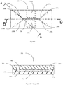
- the typical profile of a routing or separation channel is shown on the figure 2b .
- the channels have a D shape in the plane perpendicular to the axis of the channel in question, the largest width being located in the plane in contact with the cover plate when the device is assembled. They thus have a lower width "Lmin”, at the bottom of the channels, a width upper "Lmax” in the plane of the separator in contact with the cover plate when the device is assembled as well as a depth "P".
- This device of the prior art is capable of implementing methods for the preparation of biological samples by acoustophoresis such as the method according to the invention. For this, all or part of the biological sample to be treated is introduced into the inlet ports 30a and 30c of the device 10.
- a buffer solution is introduced into the inlet port 30b, the buffer and the sample being introduced at respective flow rates capable of generating a laminar flow in the separation channel.
- An ultrasonic transducer such as a piezoelectric transducer, attached to the separation channel is then activated by a control signal, so as to perform a step of separation of said biological sample by acoustophoresis.
- This separation makes it possible to promote the concentration of non-specific particles, such as food debris, present in the sample, in the outlet orifice 60b of said acoustophoresis device.
- the decomplexed sample being obtained in the outlet orifices 60a and 60c.
- the invention relates to a method applicable to different microfluidic devices allowing the processing of biological samples by acoustophoresis. These various devices are also capable of implementing the method according to the invention in an advantageous manner. These devices are particularly advantageous to implement with the method according to the invention because they make it possible to achieve higher sample throughput rates than devices of the prior art while ensuring a decomplexification rate equal to or greater than those observed in the prior art for biological samples such as food samples. On the other hand, these devices according to the invention make it possible to process a wide variety of food samples, the size of their channels, in particular of their separation channels being optimized for the different sizes of non-specific particles or debris that can be observed.
- the inlet ports and the shape of the routing channels communicating with the inlet ports can advantageously be optimized in order to accept sedimentation of non-specific particles or debris at the inputs of the microfluidic device without risk of blocking the channels of the device.
- the part of each conveying channel opposite each inlet orifice capable of receiving the biological sample may have a cavity of greater depth than the general depth of the conveying channel.
- the cavity opposite the inlet orifice is two to three times deeper than the conveying channel connected to said orifice. This cavity makes it possible to create a zone of slow or zero speed of the sample introduced, favoring the sedimentation of non-specific particles.
- the device thus formed has a better tolerance to blockages associated with the introduction of debris of large size and density.
- the separator can be made of silicon, ceramic or glass, the channels being obtained by chemical or physical etching (eg sandblasting).
- the separator can also be made of a flexible, thin polymer material such as polydimethylsiloxane (PDMS), Polypropylene or a bicomponent Polymer / Silicone (for example a Polystyrene with a flexible film of silicone or PDMS in order to ensure coupling without air from the piezoelectric transducers on the wall of the device), the channels then being obtained by molding.
- PDMS polydimethylsiloxane
- Polypropylene Polypropylene
- a bicomponent Polymer / Silicone for example a Polystyrene with a flexible film of silicone or PDMS in order to ensure coupling without air from the piezoelectric transducers on the wall of the device
- each orifice, inlet or outlet can form a reservoir so as to be able to carry out operations for storing a sample as well as depositing or pipetting operations. By attaching a heating means to an orifice, a step of incubating the sample can also be carried out.
- an orifice can be produced in a transparent or translucent material, so as to be able to directly carry out a reading of the optical density of the sample which it contains.
- each device can be used alone or in parallel so as to be able to process the same volume of biological sample at a greater rate. Indeed, if we increase the rate of introduction of fluids in the same separation channel, the decomplexification rate of the sample can decrease rapidly, the particles not having time to be separated by the acoustic wave due too short a residence time in the device.
- the amplitude of excitation (of the control signal) of the transducer (s) ) piezoelectric (s) necessary for good separation of the particles should be much greater since the resonant frequency will be reduced and consequently the radiation pressure on the particles to be focused in the center of the separation channel.
- the ultrasonic transducer by exciting the ultrasonic transducer to a higher amplitude, it can cause local heating in the separation channel. This heating is undesirable since it can cause degradation of the device as well as the viability of the particles, cells, or molecules of interest present in the separation channel.
- this heating can generate a change in density of the buffer used which can modify the propagation of the acoustic waves in the channel and disturb the separation step.
- the devices according to the invention used alone or in parallel, make it possible to obtain separation / decomplexification flow rates equal to or greater than those of the prior art while guaranteeing the viability of the particles, cells, or molecules of interest processed.
- the separation channels of the various devices according to the invention have a length which can be between 35mm and 80mm.
- the lower widths of the separation channel are for example between 300 ⁇ m and 375 ⁇ m, the upper widths are for example between and 550 ⁇ m and 625 ⁇ m.
- the depth of the separation channel can be between 100 ⁇ m and 150 ⁇ m, preferably 125 ⁇ m.
- the various devices allowing the implementation of the method according to the invention are adapted to be used with control signals of (s) ultrasonic transducer (s) attached (s) having a frequency between 300 kHz and 10 MHz, preferably 1.3 MHz alternately 1.44 MHz for the creation of a single pressure node in the center of the channel.
- the amplitude of the control signal is between 0.1V and 100V, preferably 38V.
- the cooling device is controlled by temperature in order to regulate the temperature near the ultrasonic transducer.
- the channels for conveying the inlet orifices used for the introduction of the biological sample have an angle of between 30 and 60 °, preferably 45 ° relative to the separation channel in the plan of the separator.
- This angle can easily be adapted by a person skilled in the art so as to more or less slow the rate of introduction of the fluid into the separation channel, and thus ensure the appearance of a laminar flow of the fluids in this channel.
- These routing channels are called lateral channels because they allow the fluid to be introduced towards the walls of the separation channel.
- the conveying channels to the outlet orifices used to recover or reintroduce the decomplexed sample have an angle between 30 and 60 °, preferably 45 ° relative to the separation channel in the plane of the separator. This angle can easily be adapted by a person skilled in the art so as to more or less slow the suction rate of the fluid out of the separation channel, and thus ensure the appearance of a flow.
- routing channels are also called lateral channels because they allow the fluid circulating along the walls of the separation channel to be sucked.
- the routing channels whose axis (s) is (are) identical to the axis of the separation channel are called central channels. These channels transport the concentrated sample.
- the sections of the conveying channels of the inlet and outlet orifices can be adapted.
- the sections of the conveying channels of the lateral outlet orifices (in which we find the decomplexed sample) with respect to the section of the conveying channels of the central outlet orifice (in which we find a maximum non-specific particles) can be adapted to ensure better focusing at the outlet branch between these channels.
- This device 200 comprises two inlet ports 230a, 230b, a separation channel 250 and at least two outlet ports 260a, 260b.
- the device 200 comprises two fluid parts, a separator 222 and a cover plate 221, substantially planar. These two parts are hermetically assembled.
- the inlet ports open to the separation channel, while the separation channel opens to the outlet ports via routing channels.
- the separation channel 250 opens towards the orifice 230a via the conveying channel 240a, towards the orifice 230b via the conveying channel 240b, towards the orifice 260a via the conveying channel 270a, towards the orifice 260b via the routing channel 270b.
- the device is arranged so that at least one ultrasonic transducer can be integrated into or attached to a wall of said separation channel.
- the ultrasonic transducer thus integrated or attached is capable of transmitting mechanical oscillations in multiple acoustic waves which can act on the content of the separation channel.
- the device comprises two recesses 290a, 290b, produced along the separation channel 250, in the separator 222, and capable of each receiving an ultrasonic transducer. This embodiment makes it possible to obtain a standing wave in a separator made of a material that is not very reflective of acoustic waves, the material being flexible and fine such as plastic materials, polymers, silicones.
- each ultrasonic transducer comprises a 1 ⁇ 4 wave adapter blade whose acoustic impedance is calculated to minimize the energy losses, and therefore the heating, between the ultrasonic transducer and the walls of the device.
- This resin blade covering the piezoelectric transducer (s) (produced by casting and polymerization), is defined to have an acoustic impedance intermediate between the acoustic impedance of the material used for the production of the device, and the impedance acoustics of the piezoelectric transducer (s).
- the cover plate 221 is made of Polydimethylsiloxane (PDMS) or of molded plastic material such as Polycarbonate (PC), poly (methyl methacrylate) (PMMA), polypropylene (PP), Polystyrene (PS), Acrylonitrile butadiene styrene ( ABS), Cyclic Olefin Copolymer (COC), Cyclic Olefin Polymer (COP), Polyoxymethylene (POM).
- PDMS Polydimethylsiloxane
- PC Polycarbonate
- PMMA poly (methyl methacrylate)
- PP polypropylene
- PS Polystyrene
- ABS Acrylonitrile butadiene styrene
- COC Cyclic Olefin Copolymer
- COP Cyclic Olefin Polymer
- POM Polyoxymethylene
- a buffer solution is introduced into the inlet orifice 230b, the buffer and the sample being introduced at respective flow rates capable of generating a laminar flow in the separation channel.
- An ultrasonic transducer such as a piezoelectric transducer, attached to the separation channel is then activated by a control signal, so as to perform a step of separation of said biological sample by acoustophoresis.
- This separation makes it possible to promote the concentration of non-specific particles, such as food debris, present in the sample, in the outlet orifice 260b of said acoustophoresis device.
- the decomplexed sample being obtained in the outlet orifice 260a.
- the non-specific particles are thus transferred to the buffer solution introduced into the inlet 230b.
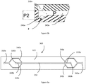
- the inlet orifice 230a here has a frustoconical shape but can also be cylindrical depending on the chosen means of introduction.
- the shape of the conveying channel 240a, opposite the orifice 230a is modified so as to include a cavity 241a of greater depth than the general depth of the conveying channel 240a.
- This cavity thus has a depth P2 with P2 of between two and three times the depth P of the routing channel.
- This cavity makes it possible to create a zone of slow or zero speed (Z) of the sample introduced, promoting the sedimentation of non-specific particles contained in the sample.
- the device thus formed has a better tolerance to blockages associated with the introduction of debris of large size and density.
- the invention also relates to a second embodiment of a device 300, capable of implementing the method according to the invention, comprising two fluid parts, a separator 322 and a cover plate (not shown), these two parts being substantially flat. These two parts are hermetically assembled. Channels are produced in the separator 322.
- the device 300 comprises two inlet orifices 330a, 330b, in fluid communication with at least one separation channel 350 by means of routing channels respectively 340a, 340c for the orifice 330a and 340b for orifice 330b.
- the separation channel 350 is also in fluid communication with two outlet orifices 360a, 360b, by means of conveying channels, respectively 370a and 370c for the orifice 360a and 370b for the orifice 360b.
- This configuration simplifies the fluid connection because it has only two inlet ports and two outlet ports.
- the collection of the decomplexed sample can be carried out in an outlet or a single collection tube.
- the conveying channels 370a and 370c to the outlet orifice 360a being directly connected by etching the channels on the device, the balancing of the pressure drops at the branching of the conveying channels to the outlet ports is significantly improved.
- the device 300 is arranged so that an ultrasonic transducer, not shown, can be integrated into or attached to a wall of said separation channel 350.
- the ultrasonic transducer thus integrated or attached is capable of transmitting mechanical oscillations in multiple acoustic waves can act on the content of the separation channel and generate a standing acoustic wave there.
- An alternating current generator associated with a signal amplifier, not shown, can be electrically connected to the transducer in order to generate a control signal from the transducer whose frequency, waveform and amplitude are known.
- the separator 322 is produced in a 1 mm thick glass plate coated with a layer of chromium and a layer of photosensitive resin. After development of the photosensitive layer, the glass is etched with hydrofluoric acid (HF).
- HF hydrofluoric acid
- the routing channels 340a and 340c, 370a and 370c have a depth P of 125 ⁇ m, a lower width Lmin, at the bottom of the channels, of 300 ⁇ m, and an upper width Lmax of 550 ⁇ m in the plane of the separator in contact with the cover plate.
- the routing channels 340b and 370b as well as the separation channel 350 have a depth P of 125 ⁇ m, a lower width Lmin, at the bottom of the channels, of 375 ⁇ m, and an upper width Lmax of 625 ⁇ m in the plane of the separator in contact with the cover plate.
- the cover plate is drilled to make the inlet and outlet orifices and then thermally bonded with the separator in order to produce a sealed assembly.
- the inlet channels 340a, 340b have an angle of 45 °, 0 ° and minus 45 ° respectively with respect to the separation channel 350 in the plane of the separator, so as to slow the flow of fluids from the routing channels with an angle of 45 ° or -45 °, 340a, 340c, with respect to the separation channel.
- the rectilinear separation channel 350 has a length of 80 mm, allowing the cells, particles or molecules to become acoustically concentrated in the routing channel 370b during the operation of the system.
- the axis of the routing channel 370b is identical to the axis of the separation channel.
- the cells, particles or molecules are acoustically concentrated in the central channel 370b, according to their density, their size and their compressibility.
- the separator 322 of the device 300 comprises two recesses (not shown) produced along the separation channel 350, and each capable of receiving an ultrasonic transducer (not shown).
- This embodiment makes it possible to obtain a standing wave in the separator 322 if the latter made of a material that is not very reflective to acoustic waves, the material being flexible and fine such as plastics, polymers, silicones.
- a silicone preferably used is Polydimethylsiloxane (PDMS).
- each ultrasonic transducer comprises a 1 ⁇ 4 wave adapter blade whose acoustic impedance is calculated to minimize the energy losses, and therefore the heating, between the ultrasonic transducer and the walls of the device.
- the covering plate (not shown) is made of PDMS or of molded plastic material such as Polycarbonate (PC), poly (methyl methacrylate) (PMMA), polypropylene (PP), Polystyrene (PS), Acrylonitrile butadiene styrene ( ABS), Cyclic Olefin Copolymer (COC), Cyclic Olefin Polymer (COP), Polyoxymethylene (POM).
- This device 300 is capable of implementing methods for preparing biological samples by acoustophoresis such as the method according to the invention. For this, all or part of the biological sample to be treated is introduced into the inlet port 330a of the device 300. A buffer solution is introduced into the inlet port 330b, the buffer and the sample being introduced at respective flow rates capable of generating a laminar flow in the separation channel. An ultrasonic transducer, such as a piezoelectric transducer, attached to the separation channel is then activated by a control signal, so as to perform a step of separation of said biological sample by acoustophoresis.
- a control signal so as to perform a step of separation of said biological sample by acoustophoresis.
- the invention also relates to a third device 400 comprising two fluid parts, a separator 422 and a cover plate (not shown), these two parts being substantially planar. These two parts are hermetically assembled. Fluid channels are produced in the separator 422.
- the device 400 comprises two inlet ports 430a, 430b, in fluid communication with at least one separation channel 450 by means of routing channels respectively 440a, 440c, for the port 430a and 440b for port 430b.
- the separation channel 450 is also in fluid communication with three outlet orifices 460a, 460b, 460c, by means of conveying channels, respectively 470a and 470c for the orifice 460a, 470b and 470d for the orifice 460c; 470b, 470f and 470e for outlet port 460b.
- the device 400 is arranged so that an ultrasonic transducer, not shown, can be integrated into or attached to a wall of said separation channel 450.
- the ultrasonic transducer thus integrated or attached is capable of transmitting mechanical oscillations in multiple acoustic waves can act on the content of the separation channel and generate a standing acoustic wave there.
- a function generator associated with a signal amplifier, not shown, can be electrically connected to the transducer in order to generate a control signal from the transducer whose frequency, waveform and amplitude are known.
- the routing channel 470b arranged in the extension of the separation channel 450, allows the realization of a second step of separation of the non-specific particles which may remain in the biological sample.
- the separator 422 is produced in a 1 mm thick glass plate coated with a layer of chromium and a layer of photosensitive resin. After development of the photosensitive layer, the glass is etched with hydrofluoric acid (HF).
- the routing channels 440a, 440c, 470a, 470c, 470e and 470f have a depth P of 125 ⁇ m, a lower width Lmin, at the bottom of the channels, of 300 ⁇ m, and an upper width Lmax of 550 ⁇ m in the plane of the separator in contact with the cover plate.
- the routing channels 440b, 470b and 470d as well as the separation channel 450 have a depth P of 125 ⁇ m, a lower width Lmin, at the bottom of the channels, of 375 ⁇ m, and an upper width Lmax of 625 ⁇ m in the plane of the separator in contact with the cover plate.
- the cover plate is drilled to make the inlet and outlet orifices and then thermally bonded with the separator in order to produce a sealed assembly.
- the inlet channels 440a, 440b, 440c have an angle of 45 °, 0 ° and minus 45 ° respectively with respect to the separation channel 450 in the plane of the separator, so as to slow the flow fluids from the conveying channels having an angle of 45 ° or - 45 °, 440a, 440c, with respect to the separation channel.
- the rectilinear separation channel 450 has a length of 80 mm, allowing, during the operation of the system, the cells, particles or molecules to become acoustically concentrated in the routing channel 470b then 470d, whose axes are identical to the axis of the separation channel.
- the separator 422 of the device 400 includes two recesses (not shown) produced along the separation channel 450, and each capable of receiving an ultrasonic transducer (not shown). This embodiment makes it possible to obtain a standing wave in the separator 422 if the latter made of a material that is not very reflective to acoustic waves, the material being flexible and fine such as plastics, polymers, silicones.
- each ultrasonic transducer includes a 1 ⁇ 4 wave adapter blade whose acoustic impedance is calculated to minimize energy losses, and therefore heating, between the ultrasonic transducer and the walls of the device.
- the covering plate (not shown) is made of PDMS or of molded plastic material such as Polycarbonate (PC), poly (methyl methacrylate) (PMMA), polypropylene (PP), Polystyrene (PS), Acrylonitrile butadiene styrene ( ABS), Cyclic Olefin Copolymer (COC), Cyclic Olefin Polymer (COP), Polyoxymethylene (POM).
- This device 400 is capable of implementing methods for preparing biological samples by acoustophoresis such as the method according to the invention. For this, all or part of the biological sample to be treated is introduced into the inlet port 430a of the device 400. A buffer solution is introduced into the inlet port 430b, the buffer and the sample being introduced at respective flow rates capable of generating a laminar flow in the separation channel. An ultrasonic transducer, such as a piezoelectric transducer, attached to the separation channel is then activated by a control signal, so as to perform a step of separation of said biological sample by acoustophoresis.
- a control signal so as to perform a step of separation of said biological sample by acoustophoresis.
- This separation makes it possible to promote the concentration of non-specific particles, such as food debris, present in the sample, in the channel 470b of said acoustophoresis device.
- the decomplexed sample is obtained in the outlet port 460a.
- a second step of separation of said biological sample by acoustophoresis is carried out on the part resulting from the first separation in channel 470b.
- This separation makes it possible to promote the concentration of non-specific particles, such as food debris, present in the sample, in the outlet orifice 460c of said acoustophoresis device.
- the second decomplexed sample is obtained in the outlet port 460b.
- the collection and mixing of the decomplexed samples from the outlet ports 460a and 460b makes it possible to increase the collection yield of the microorganisms present in the biological sample. Indeed, the microorganisms entrained with the non-specific particles during the first separation in the channel 470b are likely to be separated by acoustophoresis in this channel 470b and can thus be collected following this second separation in the orifice 460b.
- the relative position and the length of the second separation channel 470b with respect to the main separation channel 450 is chosen according to the applications, performances and desired flow rates.
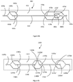
- the invention also relates to a fourth embodiment of a device 1300 comprising two fluid parts, a separator 1322 and a cover plate (not shown), these two parts being substantially planar. These two parts are hermetically assembled. Channels are made in the separator 1322.
- the device 1300 comprises two inlet ports 1330a, 1330b, in fluid communication with a first channel separation 1350 by means of routing channels 1340a, 1340c respectively for the orifice 1330a and 1340b for the orifice 1330b.
- the separation channel 1350 is in fluid communication with an outlet orifice 1360b, by means of a routing channel 1370b.
- the separation channel 1350 is also in fluid communication with a second separation channel 1350 'via two routing channels 1370a and 1370c.
- the second separation channel 1350 ' is in fluid communication with an outlet port 1360b', via a delivery channel 1370b 'and in fluid communication with an outlet port 1360a, through two delivery channels 1370a 'and 1370c'.
- the device 1300 also includes an inlet orifice 1330b ', in fluid communication with the second separation channel 1350' via a routing channel 1340b '.
- the device 1300 is arranged so that one or more ultrasonic transducer (s), not shown, can be integrated into or attached to a wall of said separation channels 1350 and 1350 '.
- the ultrasound transducer (s) thus integrated or attached is (are) capable (s) of transmitting mechanical oscillations in multiple acoustic waves which can act on the content of the separation channels and generate a standing acoustic wave.
- An alternating current generator associated with a signal amplifier, not shown, can be electrically connected to the transducer (s) in order to generate a control signal whose frequency, waveform and amplitude are known.
- This configuration improves the purity of the decomplexed sample. Indeed, after having concentrated the non-specific particles towards the outlet orifice 1360b, the decomplexed sample is injected into the second separation channel 1350 'via the channels 1370a and 1370c. The decomplexed sample is then separated a second time from the non-specific particles which may still be present, these being found in the orifice 1360b '. The second decomplexed sample is obtained in the outlet port 1360a.
- the separator 1322 is produced in a 1 mm thick glass plate coated with a layer of chromium and a layer of photosensitive resin. After development of the photosensitive layer, the glass is etched with hydrofluoric acid (HF).
- the routing channels 1340a and 1340c, 1370a, 1370c, 1370a 'and 1370c' have a depth P of 125 ⁇ m, a smaller width Lmin, at the bottom of the channels, 300 ⁇ m, and a larger width Lmax of 550 ⁇ m in the plane of the separator in contact with the cover plate.
- the routing channels 1340b, 1340b ', 1370b and 1370b' as well as the separation channels 1350 and 1350 ' have a depth P of 125 ⁇ m, a smaller width Lmin, at the bottom of the channels, 375 ⁇ m, and a larger width Lmax of 625 ⁇ m in the plane of the separator in contact with the cover plate.
- the cover plate is drilled to make the inlet and outlet ports then thermally bonded with the separator in order to achieve a tight assembly.
- the inlet channels 1340a, 1340b have an angle of 45 °, 0 ° and minus 45 ° respectively with respect to the separation channel 1350 in the plane of the separator, so as to slow the flow of fluids coming from the routing channels having an angle of 45 ° or -45 °, 1340a, 1340c, with respect to the separation channel 1350.
- the straight 1350 separation channel has a length of 19.5 mm, allowing the cells, particles or molecules to become acoustically concentrated in the channel 1370b during operation of the system.
- the axis of the routing channel 1370b is identical to the axis of the separation channel.
- the routing channels 1370a, 1370b, 1340b ' have an angle of 45 °, 0 ° and minus 45 ° respectively with respect to the separation channel 1350' in the plane of the separator, so as to slow the flow of fluids from the routing channels having an angle of 45 ° or - 45 °, 1340a, 1340c, with respect to the second separation channel 1350 '.
- the second rectilinear separation channel 1350 ′ has a length of 19.5 mm, allowing the cells, particles or molecules to become acoustically concentrated in the routing channel 1370b ′ during the operation of the system.
- the axis of the routing channel 1370b ' is identical to the axis of the separation channel 1350'.
- the separator 1322 of the device 1300 comprises four recesses (not shown) produced along the separation channels 1350 and 1350 ', and each capable of receiving an ultrasonic transducer (not shown).
- This embodiment makes it possible to obtain a standing wave in the separator 1322 if the latter is made of a material that is not very reflective to acoustic waves, the material being flexible and fine such as plastics, polymers, silicones.
- a silicone preferably used is Polydimethylsiloxane (PDMS).
- each ultrasonic transducer comprises a 1 ⁇ 4 wave adapter blade whose acoustic impedance is calculated to minimize the energy losses, and therefore the heating, between the ultrasonic transducer and the walls of the device.
- the covering plate (not shown) is made of PDMS or of molded plastic material such as Polycarbonate (PC), poly (methyl methacrylate) (PMMA), polypropylene (PP), Polystyrene (PS), Acrylonitrile butadiene styrene ( ABS), Cyclic Olefin Copolymer (COC), Cyclic Olefin Polymer (COP), Polyoxymethylene (POM).
- This device 1300 is capable of implementing methods for the preparation of biological samples by acoustophoresis such as the method according to the invention.
- all or part of the biological sample to be treated is introduced into the inlet port 1330a of the device 1300.
- a buffer solution is introduced into the inlet ports 1330b and 1330b ', the buffers and the sample being introduced at respective flow rates capable of generating a laminar flow in the separation channels 1350 and 1350 ′.
- One or more ultrasonic transducer (s) attached to the separation channels is (are) then activated by a control signal, so as to carry out two successive steps of separation of said biological sample by acoustophoresis.
- This separation makes it possible to promote for the first time the concentration of non-specific particles, such as food debris, present in the sample, in the outlet orifice 1360b.
- a second separation makes it possible to promote a second time the concentration of non-specific particles, such as food debris still present in the decomplexed sample from the channels 1370a and 1370c in the outlet orifice. 1360b '.
- the sample decomplexed a second time and having improved purity being obtained in the outlet orifice 1360a.
- the relative position and the length of the second separation channel 1350 'with respect to the main separation channel 1350' is chosen according to the applications, performances and desired flow rates.
- the invention also relates to a fifth device 1400 comprising two fluid parts, a separator 1422 and a cover plate (not shown), these two parts being substantially planar. These two parts are hermetically assembled. Fluid channels are produced in the separator 1422.
- the device 1400 comprises two inlet ports 1430a, 1430b, in fluid communication with a first separation channel 1450 by means of routing channels 1440a, 1440c respectively, for the orifice 1430a and 1440b for port 1430b.
- the first separation channel 1450 is also in fluid communication with an outlet orifice 1460a, by means of routing channels 1470a and 1470c.
- the first separation channel 1450 is finally in fluid communication with a second separation channel 1450 ', by means of routing channels 1440a' and 1440c '.
- the device 1400 also includes an inlet orifice 1430b ', in fluid communication with the second separation channel 1450 via the routing channel 1440b'.
- the second separation channel 1450 ′ is also in fluid communication with two outlet orifices 1460b, 1460c, by means of conveying channels, respectively 1470d for the orifice 1460c; 1470e and 1470f for the outlet port 1460b.
- the device 1400 is arranged so that one or more ultrasonic transducer (s), not shown, can be integrated into or attached to a wall of said separation channels 1450 and 1450 '.
- the ultrasound transducer (s) thus integrated or attached is (are) capable (s) of transmitting mechanical oscillations in multiple acoustic waves which can act on the content of the separation channels and generate a standing acoustic wave.
- An alternating current generator associated with a signal amplifier, not shown, can be electrically connected to the transducer (s) in order to generate a control signal whose frequency, waveform and amplitude are known.
- the separator 1422 is produced in a 1 mm thick glass plate coated with a layer of chromium and a layer of photosensitive resin. After development of the photosensitive layer, the glass is etched with hydrofluoric acid (HF).
- the routing channels 1440a, 1440c, 1470a, 1470c, 1470e and 1470f have a depth P of 125 ⁇ m, a lower width Lmin, at the bottom of the channels, of 300 ⁇ m, and an upper width Lmax of 550 ⁇ m in the plane of the separator in contact with the cover plate.
- the routing channels 1440b, 1470b and 1470d as well as the separation channels 1450 and 1450 ′ have a depth P of 125 ⁇ m, a lower width Lmin, at the bottom of the channels, of 375 ⁇ m, and an upper width Lmax of 625 ⁇ m in the plane of the separator in contact with the cover plate.
- the cover plate is drilled to make the inlet and outlet orifices and then thermally bonded with the separator in order to produce a sealed assembly.
- the conveying channels 1440a, 1440c have an angle of 45 ° and minus 45 ° respectively with respect to the separation channel 1450 in the plane of the separator, so as to slow the flow of fluids coming from these conveying channels.
- the routing channels 1440a ', 1440c' have an angle of 45 ° and minus 45 ° respectively with respect to the separation channel 1450 'in the plane of the separator.
- the straight separation channels 1450 and 1450 ′ have a length of 22.5 mm, allowing, during the operation of the system, cells, particles or molecules to become acoustically concentrated in the routing channel 1470b then 1470d, whose axes are identical to the axes of the separation channels.
- the separator 1422 of the device 1400 comprises four recesses (not shown) produced along the separation channels 1450 and 1450 ', and each capable of receiving an ultrasonic transducer (not shown). This embodiment makes it possible to obtain a standing wave in the separator 1422 if the latter made of a material that is not very reflective to acoustic waves, the material being flexible and fine such as plastics, polymers, silicones.
- each ultrasonic transducer comprises a 1 ⁇ 4 wave adapter blade whose acoustic impedance is calculated to minimize the energy losses, and therefore the heating, between the ultrasonic transducer and the walls of the device.
- the cover plate (not shown) is made of PDMS or of molded plastic material such as Polycarbonate (PC), poly (methyl methacrylate) (PMMA), polypropylene (PP), Polystyrene (PS), Acrylonitrile butadiene styrene (ABS), Cyclic Olefin Copolymer (COC), Cyclic Olefin Polymer (COP), Polyoxymethylene (POM).
- This device 1400 is capable of implementing methods for preparing biological samples by acoustophoresis such as the method according to the invention. For this, all or part of the biological sample to be treated is introduced into the inlet port 1430a of the device 1400. A buffer solution is introduced into the inlet port 1430b, the buffer and the sample being introduced. at respective flow rates capable of generating a laminar flow in the separation channel 1450. An ultrasonic transducer, such as a piezoelectric transducer, attached to the separation channel 1450 is then activated by a control signal, so as to perform a step of separation of said biological sample by acoustophoresis.
- a control signal so as to perform a step of separation of said biological sample by acoustophoresis.
- This separation makes it possible to promote the concentration of non-specific particles, such as food debris, present in the sample, in the conveying channel 1470b of said acoustophoresis device.
- the decomplexed sample is obtained in the outlet port 1460a.
- a second step of separation of said concentrated sample by acoustophoresis is also carried out on the part resulting from the first separation in the channel 1450 '. For this, a second clean buffer is introduced simultaneously into the inlet orifice 1430b ′ in order to extract the species of residual interest still present in the concentrated sample.
- This separation makes it possible to promote the concentration of non-specific particles, such as food debris, always present in the concentrated sample, in the outlet orifice 1460c of said acoustophoresis device.
- the collection and mixing of the decomplexed samples from the outlet orifices 1460a and 1460b makes it possible to increase the collection yield of the microorganisms initially present in the biological sample. Indeed, microorganisms entrained with non-specific particles during the first separation towards channel 1450 'via channels 1440a' and 1440c 'are likely to be separated by acoustophoresis in this channel 1450' and can thus be collected following this second separation in port 1460b. The extraction yield of microorganisms and thus improved.
- the relative position and the length of the second separation channel 1450 'with respect to the main separation channel 1450' is chosen according to the applications, performances and desired flow rates.
- two buffer solutions of different type or density are introduced into the inlet orifices 1430b and 1430b '.
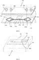
- the device can comprise, around the conveying channel towards an outlet orifice containing the decomplexed sample, movable magnet supports allowing sample capture brought into contact with magnetic particles such as magnetic silica.
- two movable magnet supports 2000 are arranged.
- the magnets thus arranged on either side of the channel routing to the outlet orifice 360a make it possible to continuously capture microorganisms by displacement of magnetic silica particles 2100 perpendicular to the flow of the decomplexed sample.
- the movement M of the magnet supports is carried out for example perpendicular to the channel and alternately between the two supports in order to favor the mixing of the sample and the particles.
- the device can comprise, around the conveying channel towards an outlet orifice containing the decomplexed sample, Di ElectroPhorese electrodes ( DEP) deposited on the surface of the device at the outlet.
- DEP Di ElectroPhorese electrodes
- two Di ElectroPhorese (DEP) 3000 electrodes are arranged in order to allow the carrying out of a specific capture step.
- These electrodes can be either functionalized with capture antigens in the case of capture on a panel of sought-after species, or nonfunctionalized then using only the well-known properties of capture by the charge of the DEP technique.
- the identification of the species (s) of interest captured can in both cases be confirmed or carried out for example by Raman 3100 identification.
- the figure 8 represents a sixth device 500 allowing the implementation of the method according to the invention and comprising two fluid parts, a separator 522 and a cover plate 521, these two parts being substantially planar. These two parts are hermetically assembled. Fluidic channels are produced in the separator 522.
- the device 500 comprises two inlet ports 530a, 530b, produced in the cover plate 521, in fluid communication with at least one separation channel 550 by means of routing channels respectively 540a, 540c, for port 530a and 540b for port 530b.
- the separation channel 550 is also in fluid communication with two outlet orifices 560a, 560b, by means of conveying channels, respectively 570a and 570c for the orifice 560a, 570b for the orifice 560b.
- the inlet and outlet openings form reservoirs so as to be able to carry out operations for depositing a sample to be decomplexed by pipetting and buffer solution as well as operations for connection to a pressurized or vacuum controlled system and regulated on flow measurement and allowing reproducible control of the introduction and flow of biological samples and buffer into the separation channel.
- the device 500 is arranged so that an ultrasonic transducer, not shown, can be integrated into or attached to a wall of said separation channel 550.
- the ultrasonic transducer thus integrated or attached is capable of transmitting mechanical oscillations in waves multiple acoustics that can act on the content of the separation channel and generate a standing acoustic wave.
- An alternating current generator (not shown) can be electrically connected to the transducer in order to generate a control signal from the transducer whose frequency, waveform and amplitude are known.
- the separator 522 is produced in a 1 mm thick glass plate coated with a layer of chromium and a layer of photosensitive resin. After development of the photosensitive layer, the glass is etched with hydrofluoric acid (HF).
- the routing channels 540a and 540c, 570a, 570c have a depth P of 125 ⁇ m, a smaller width Lmin, at the bottom of the channels, of 300 ⁇ m, and an upper width Lmax of 550 ⁇ m in the plane of the separator in contact. with the cover plate.
- the routing channels 540b, 570b as well as the separation channel 550 have a depth P of 125 ⁇ m, a lower width Lmin, at the bottom of the channels, of 375 ⁇ m, and an upper width Lmax of 625 ⁇ m in the plane of the separator. contact with the cover plate.
- the cover plate is drilled to make the inlet and outlet orifices and then thermally bonded with the separator in order to produce a sealed assembly.
- the inlet port routing channels (540a, 540b, 540c) have an angle of respectively 45 °, 0 ° and minus 45 ° relative to the separation channel 550 in the plane of the separator, so as to slow down the flow rate of the fluids coming from the conveying channels having an angle of 45 ° or -45 °, 540a, 540c, with respect to the separation channel.
- the rectilinear separation channel 550 has a length of 80 mm, allowing the cells, particles or molecules to become acoustically concentrated in the routing channel 570b during the operation of the system.
- the axis of the routing channel 570b is identical to the axis of the separation channel 550.
- the separator 522 of the device 500 comprises two recesses, 590a, 590b, produced along the separation channel 550, and each capable of receiving an ultrasonic transducer (not shown).
- This embodiment makes it possible to obtain a standing wave in the separator 522 if the latter made of a material that is not very reflective to acoustic waves, the material being flexible and fine such as plastics, polymers, silicones.
- a silicone preferably used is Polydimethylsiloxane (PDMS).
- each ultrasonic transducer comprises a 1 ⁇ 4 wave adapter blade whose acoustic impedance is calculated to minimize the energy losses, and therefore the heating, between the ultrasonic transducer and the walls of the device.
- the cover plate (not shown) is made of PDMS or of molded plastic material such as Polycarbonate (PC), poly (methyl methacrylate) (PMMA), polypropylene (PP), PolyStyrene (PS), Acrylonitrile butadiene styrene ( ABS), Cyclic Olefin Copolymer (COC), Cyclic Olefin Polymer (COP), Polyoxymethylene (POM).
- PC Polycarbonate
- PMMA poly (methyl methacrylate)
- PP polypropylene
- PS PolyStyrene
- ABS Acrylonitrile butadiene styrene
- COC Cyclic Olefin Copolymer
- COP Cyclic Olefin Polymer
- POM Polyoxymethylene
- This device 500 is capable of implementing methods for the preparation of biological samples by acoustophoresis such as the method according to the invention.
- all or part of the biological sample to be treated is introduced into the inlet port 530a of the device 500.
- a buffer solution is introduced into the inlet port 530b, the buffer and the sample being introduced at respective flows capable of generating a laminar flow in the separation channel.
- An ultrasonic transducer, such as a piezoelectric transducer, attached to the separation channel is then activated by a control signal, so as to perform a step of separation of said biological sample by acoustophoresis.
- This separation makes it possible to promote the concentration of non-specific particles, such as food debris, present in the sample, in the outlet orifice 560b of said acoustophoresis device.
- the decomplexed sample being obtained in the outlet port 560a.
- the figure 9 has a support 600 for devices with a device 500 arranged and maintained on the support.
- This support makes it possible, for example, to process the same biological sample simultaneously on several devices or several different samples simultaneously by connecting one or more reservoirs containing the sample (s) such as a syringe to the different inlet orifices.
- devices arranged on the support may comprise an articulated cover, not shown, making it possible to directly connect the inlet and outlet openings of the device to pressurizing and / or vacuum means, when the cover is closed.
- This support comprises one or more receiving bases (not shown) of devices according to the invention, making it possible to place and maintain said devices. The devices can be maintained mechanically or by suctioning the devices on the receiving base (s).
- Ultrasonic transducers 690 can be placed in these bases so as to be able to create a standing wave in each of the devices arranged on the support.
- the transducer being attached to the device when the latter is disposed in said base.
- a single ultrasonic transducer covering several devices can be arranged so as to be able to create a standing wave in each of the devices arranged on the support.
- a receiving space 610 makes it possible in particular to attach a heating system (not shown) to at least one of the outlet orifices of the device disposed on the support. Said heating system making it possible to incubate the biological sample treated and contained in at least one of the outlet orifices 560a, 560b.
- the reception space 610 can comprise a means for measuring the optical density of the sample contained in at least one of the exit orifices 560a, so as to avoid additional manipulations for carrying out this operation.
- the support can be placed directly on an agitator or include an agitation means so as to carry out a step of agitation of the biological sample contained in one of the outlet orifices, before, during or following a incubation stage.
- This support 600 also makes it possible to arrange and maintain various devices 200, 300, 400, 500, 800, according to the invention, the receiving space 610 being able to be easily adapted by a person skilled in the art.
- the figure 10 presents a support 700 for devices allowing the implementation of the method according to the invention shown with four devices 500 arranged and maintained on the support.
- This support makes it possible, for example, to process the same biological sample simultaneously on several devices by connecting a reservoir containing the biological sample such as a syringe to the various inlet orifices 530a of the devices arranged on the support.
- the support makes it possible to arrange the devices so as to present each of the inlet and outlet orifices aligned on the same axis and according to a defined spacing. This spacing can advantageously be equivalent or multiple to that of the pitch of a microplate known to those skilled in the art.
- This support comprises several receiving bases (not shown) of devices according to the invention, making it possible to place and maintain said devices.
- Ultrasonic transducers (not shown), or a transducer common to several devices, can be arranged in these bases so as to be able to create a standing wave in each of the devices arranged on the support. The transducer being attached to the device when the latter is disposed in said base.
- the support 700 can comprise several reception spaces (not shown) making it possible in particular to attach to at least one of the outlet orifices of each of the devices arranged on the support, a heating system (not shown) making it possible to incubate the biological sample treated and contained in at least one of the outlet orifices 560a, 560b.
- each of the reception spaces can comprise a means for measuring the optical density of the sample contained in at least one of the outlet orifices 560a, so as to avoid additional manipulations for carrying out this operation.
- the support 700 can be placed directly on an agitator or include an agitation means so as to carry out a step of agitation of the biological sample contained in one of the outlet orifices, before, during or after an incubation stage.
- This support 700 also makes it possible to have several of the different devices 200, 300, 400, 500, 800 in parallel, according to the invention, the number of reception bases being able to be easily adapted by a person skilled in the art.
- the different devices arranged on the support 700 can be of the same type or of different types.
- the Figures 11, 12a and 12b represent a multiplex device 800 allowing the implementation of the method according to the invention and comprising three fluid parts, a separator 822, a cover plate 821 and a base 823, these three parts being substantially flat. These three parts are hermetically assembled. Fluid channels are produced in the separator 822.
- the device 800 comprises two inlet ports 830a, 830b, in fluid communication with eight separation channels 850, by means of a network of introduction channels 841, 842, and channels routing.
- the separation channels 850 communicate with the orifice 830a via the network of introduction channels 841 as well as by the routing channels 840a, 840c.
- the separation channels 850 communicate with the orifice 830b via the network of introduction channels 842 as well as through the routing channel 840b.
- the separation channels 850 are also in fluid communication with two outlet orifices 860a, 860b, through a network of suction channels 843, 844 and routing channels.
- the separation channels 850 communicate with the orifice 860a via the network of suction channels 843 as well as by the routing channels, 870a, 870c.
- the separation channels 850 communicate with the orifice 860b via the network of suction channels 844 as well as via the routing channel 870b.
- Eight separation channels 850 are shown, each of channels 850 and associated routing channels forming a fluidic pattern repeated eight times.
- the device 800 is arranged so that an ultrasonic transducer, not shown, can be integrated into or attached to a wall of said separation channels 850.
- the ultrasonic transducer thus integrated or attached is capable of transmitting mechanical oscillations in multiple acoustic waves can act on the content of each separation channel and generate a standing acoustic wave there.
- An alternating current generator (not shown) can be electrically connected to the transducer in order to generate a control signal from the transducer whose frequency, waveform and amplitude are known.
- through openings 880 or engravings of a depth greater than or equal to that of the separation channels are made in the separator. These openings or etchings are distributed on each side of the separation channels 850.
- the networks of introduction channels 841, 842 make it possible to divide the flow, for example of biological sample or of buffer introduced into the inlet orifices 830a and 830b.
- This parallelization of the separation channels makes it possible to process a sample volume by acoustophoresis at higher flow rates than on a conventional device without degrading the extraction performance by increasing the sample flow rate (in ⁇ L / min).
- the suction networks 843, 844 make it possible to collect the treated samples or buffer in a single outlet orifice. These networks also make it possible to ensure a pressure balance downstream of the separation stage by acoustophoresis.
- This device 800 is capable of implementing methods for the preparation of biological samples by acoustophoresis such as the method according to the invention. For this, all or part of the biological sample to be treated is introduced into the inlet port 830a of the device 800. A buffer solution is introduced into the inlet port 830b, the buffer and the sample being introduced. at respective flow rates capable of generating a laminar flow in the separation channels. An ultrasonic transducer, such as a piezoelectric transducer, attached to the separation channels is then activated by a control signal, so as to perform a step of separation of said biological sample by acoustophoresis.
- a control signal so as to perform a step of separation of said biological sample by acoustophoresis.
- this separation makes it possible to promote the concentration of non-specific particles, such as food debris, present in the sample, in the outlet orifice 860b.
- the decomplexed sample being obtained in the outlet port 860a. Since this device has eight separation channels, a biological sample processing throughput eight times higher than a state-of-the-art device can be achieved on the same device. Similarly, a sample volume (in mL) eight times larger can be processed in the same time without modification of flow rate ( ⁇ L / min) thus keeping the extraction performance intact.
- this fifth multiplex device comprises two entry ports in fluid communication with at least two separation channels, via a network of introduction channels and routing channels. Said separation channels also communicate with two outlet orifices through a network of suction and routing channels. This embodiment associated with each of the separation channels makes it possible to adapt the sample processing rate according to the desired application, by multiplying the number of parallelized separation channels and associated routing channels.
- connection device 900 making it possible to connect orifices of a microfluidic device to an introduction or suction means.
- This device is shown connected to a device 10 of the state of the art.
- the connection device 900 comprises an input connector 910, and an output connector 920.
- the input connector 910 comprises three routing channels 930a, 930b, 930c capable of cooperating with the input orifices of the device 10, respectively 30a, 30b, 30c.
- the input connector 910 thus makes it possible to come to connect means for introducing a biological sample or a buffer solution without directly handling the microfluidic device 10.
- a tube for introducing a syringe 931b is connected to the routing channel 930b in order to be able to introduce a solution into the orifice 30b.
- a similar arrangement is made opposite the inlet ports 30a and 30c in order to be able to introduce the biological sample into the inlet ports 30a and 30c.
- the outlet connector 920 comprises three routing channels 960a, 960b, 960c able to cooperate with the outlet orifices of the device 10, respectively 60a, 60b, 60c.
- the output connector 920 thus makes it possible to come to connect suction means or means for collecting biological sample or buffer solution without directly handling the microfluidic device 10 and without requiring a suction or pumping means connected at the outlet of the microfluidic device.
- a collection tube 961b visible on the figure 13b such as an "Eppendorf" tube, is placed opposite the routing channel 960b in order to be able to collect the solution coming from the outlet orifice 60b.
- a similar arrangement is made opposite the outlet orifices 60a and 60c in order to collect the decomplexed sample directly in collection tubes.
- the device 10 is arranged between the connectors 910 and 920 and a support, not shown.
- the connectors 910 and 920 are held on said support by any means, in particular by screwing, by force mounting or by return springs, so as to ensure a hermetic connection with the inlet and outlet orifices of the device.
- the connectors include O-rings 990 in order to guarantee this tightness when the connector is held.
- the geometry of this connection device 900, connectors 910 and 920 and the number of connector routing channels can easily be adapted to be used with one or more devices 200, 300, 400, 500, 800, depending on the invention.
- the figure 14 represents an air regulation system 1000 and associated connection devices 1100 allowing the implementation of the method according to the invention by slaving of the introduction and the aspiration of the introduced liquids.
- the system is here represented with a device 10 of the state of the art represented here according to section AA of the figure 1 .
- the regulation system 1000 comprises a pressure or vacuum generator 1010.
- the generator 1010 comprises two pressure outlets 1020a and 1020b capable of delivering the air pressure necessary for the introduction of the biological sample or of the buffer solution d 'a method according to the invention at a regulated flow rate in a microfluidic device.
- the generator 1010 also includes two vacuum inlets 1040a and 1040b capable of generating a differential air pressure sufficient to aspirate the biological sample and the buffer solution of a method according to the invention at a regulated flow rate in a microfluidic device.
- the vacuum inputs 1040a and 1040b are connected to the device via two air flow sensors 1050a and 1050b in order to measure and control the regulation of the pressure of the air introduced or the suction vacuum of the sample and buffer solution of a method according to the invention. This regulation thus makes it possible to obtain a constant flow of separation and decomplexification of the biological sample while limiting the risks of pressure drop.
- connection device 1100 is connected to the inlet and outlet ports of the device via the connection device 1100.
- This device comprises an inlet connector per inlet port as well as an outlet connector per port Release. Only the input connectors 1120b and 1140b are shown for the sake of clarity of the figure.
- the connection device 1100 also comprises a cover 1110 disposed and maintained on the device 10.
- the cover 1110 comprises a reservoir facing each of the inlet and outlet orifices of the device 10. Only the reservoir 1130b, cooperating with the orifice 30b and the reservoir 1160b cooperating with the orifice 60b are shown for the sake of clarity of the figure.
- the cover 10 can be made of plastic, for example by injection and makes it possible to cover a device in order to present opposite each inlet and outlet orifice of the device held in the tanks. These reservoirs can in particular be used for depositing and collecting samples and buffer solutions.
- the cover is held on a support, not shown, so as to make a hermetic connection with the orifices of the device 10.
- the cover can be held on the support by any means, in particular by screwing, by force mounting or by pressure d 'a return spring.
- An input connector 1120b is able to be disposed and maintained on the cover 1110 so as to cooperate with the reservoir 1130b of said cover.
- An outlet connector 1140b is also able to be disposed and maintained on the cover 1110 so as to cooperate with the reservoir 1160b of said cover.
- the connectors advantageously have O-rings and are held on the cover by screws or springs.
- the connectors can also be held on the cover by any means, in particular by screwing, by force fitting or by the pressure of a return spring.
- the geometry of this connection device 1100 and in particular of the connectors can easily be adapted to be used with a device 200, 300, 400, 500, 800, allowing the implementation of the method according to the invention.
- the examples below will allow a better understanding of the present invention. However, these examples are given only by way of illustration and should in no case be regarded as limiting the scope of the invention in any way.
- a microfluidic device is produced in accordance with the device shown in the figure 1 .
- the three inlet ports 30a, 30b, 30c, and the three outlet ports 60a, 60b, 60c are connected to introduction means, such as syringes (Becton Dickinson Plastipak TM, Spain) via an assembly comprising a pipette tip (Eppendorf, United Kingdom) connected to a Tygon tube (0.03 in ID, 0.09 in OD, Cole-Parmer, United Kingdom).
- a pipette tip is hermetically glued to each of the orifices, a tygon tube is then inserted then glued into the pipette tip and finally assembled with the tip of the syringe.
- three introduction syringes 130a, 130b, 130c make it possible to introduce a fluid into each of the inlet orifices 30a, 30b, 30c, while three suction means such as syringes 140a, 140b, 140c, make it possible to aspirate the fluid in each of the outlet orifices 60a, 60b, 60c.
- a connection device 900 can be used to connect each syringe to the device.
- the three suction syringes 140a, 140b, 140c ensure a balance of pressure and flow in the three delivery channels to the outlet orifices, downstream of the separation channel.
- the device is less subject to possible blockages which may be due to particles of large size hindering the circulation of the fluid in one of the channels.
- Syringe pumps Hard Apparatus, United Kingdom
- a 10mm x 30mm piezoelectric transducer made of ceramic (Pz26, Ferroperm Piezoceramics, USA) with a resonance frequency range of 1 MHz and 2 MHz is fixed to the device 10 by an ultrasound gel (Anagel TM United Kingdom). This transducer is used to generate ultrasound used to induce a standing wave between the walls of the separation channel.
- a movement of the particles induced by the phenomenon of acoustophoresis can thus be obtained by the application of an alternating current (AC) to the transducer.
- This control signal is introduced into the circuit by a function generator (Agilent, model 33210A, 10 MHz on the function / arbitrary waveform generator, United Kingdom) in sinusoidal operating mode.
- An amplifier (Amplifier research, model 1W1000B, 1-1000 MHz, AR) is used to amplify the signal from the function generator and obtain the amplitude necessary to entrain the particles.
- An oscilloscope (Tektronix, model 1042 SCT, USA) is connected in parallel with the sensor to measure the operating voltage.
- a step of enrichment of the sample is carried out by incubation for 4 h at 37 ° C. then an aliquot of 10 ml of enriched broth is collected, taken from the side of the filtered part of the TEMPO® bag (the TEMPO bag ® with a side filter allowing pre-filtration of the sample). No subsequent filtration step is carried out on this batch.
- a second batch of samples, prepared as above, is obtained by mixing 10 g of ground beef and 90 ml of BPW is produced in the same way as the first batch of sample.
- an isolated colony of Salmonella typhimurium isolated from a culture on Trypticase Soy Agar culture medium (TSA; bioMérieux, ref. 43011, France) is suspended in 9 ml of Trypticase Soy broth (TSB; bioMérieux, ref. 42100, France) and then incubated at 37 ° C for 18 h.
- TSA Trypticase Soy Agar culture medium
- a TSA culture medium is seeded with 100 ⁇ l of d-5 and incubated at 37 ° C. overnight. This step is carried out in duplicate. The actual number of microorganisms present in the initial sample was calculated based on the dilution and the number of colonies counted on the medium. From these dilutions containing pathogens, a first series of 10 ml of chicken broth enriched by incubation (prepared as described above) was seeded with 0.1 ml of 10 6 CFU.mL -1 Salmonella typhimurium for obtain a final concentration of 10 4 CFU.ml -1 .
- a second series of 10 ml of chicken broth mixed with BPW and prepared without the incubation step is added with 0.1 ml of 10 5 CFU.mL -1 of Salmonella typhimurium to obtain a final concentration of 10 3 CFU. mL -1 .
- 10 ml of beef broth at 10 3 CFU ml -1 are prepared, without the incubation step, as well as samples at 10 4 CFU ml -1 , with the incubation step.
- 0.5 mL of chicken sample is introduced by two syringes into the inlet orifices 30a and 30c of a device as described above at a flow rate of 10 ⁇ L.min -1 by the routing channels 40a, 40c.
- a BPW broth is introduced by a syringe into the inlet port 30b at a flow rate of 30 ⁇ L.min -1 .
- 0.5 ml of beef sample is introduced by two syringes into the inlet orifices 30a and 30c of a device as described above at a flow rate of 10 ⁇ L. min -1 by the routing channels 40a, 40c.
- a BPW broth is introduced by a syringe into the inlet port 30b at a flow rate of 30 ⁇ L.min -1 .
- the total number of viable colonies obtained by seeding and counting on TSA media (bioMérieux, France), also shows the non-invasive aspect of the preparation method as described in the invention.
- part of the decomplexified samples from the lateral outlets
- concentrated samples from the central outlet
- were spread on a chromogenic medium chromlD®- Salmonella bioMérieux, ref 43621, France
- samples with a pathogen concentration of 10 2 -10 3 CFU.mL -1 are made in the sample of enriched food matrix. These samples were prepared by mixing 10 g of skinless chicken or beef samples with 90 ml of BPW medium, and homogenized by a homogenizing mill (Masticator, IUL, Germany) and treated without an incubation step. 0.1 ml of approximately 10 5 CFU.mL -1 of Salmonella typhimurium was then seeded in 10 ml of BPW-enriched sample in order to obtain the final concentration of 10 3 CFU.ml -1 .
- a decomplexification rate of 20% to 50% by the method according to the invention has also been observed ( figure 20 ).
- a very high level of Salmonella typhimurium could be recovered in the outlet ports 60a and 60c, by a factor of 5 to 10 compared to the outlet port 60b ( figure 21 ).
Landscapes
- Chemical & Material Sciences (AREA)
- Health & Medical Sciences (AREA)
- Life Sciences & Earth Sciences (AREA)
- Biochemistry (AREA)
- General Health & Medical Sciences (AREA)
- Immunology (AREA)
- Physics & Mathematics (AREA)
- General Physics & Mathematics (AREA)
- Analytical Chemistry (AREA)
- Pathology (AREA)
- Engineering & Computer Science (AREA)
- Food Science & Technology (AREA)
- Dispersion Chemistry (AREA)
- Bioinformatics & Cheminformatics (AREA)
- Organic Chemistry (AREA)
- Genetics & Genomics (AREA)
- Wood Science & Technology (AREA)
- Zoology (AREA)
- Medicinal Chemistry (AREA)
- Biomedical Technology (AREA)
- General Engineering & Computer Science (AREA)
- Microbiology (AREA)
- Biotechnology (AREA)
- Apparatus Associated With Microorganisms And Enzymes (AREA)
- Measuring Or Testing Involving Enzymes Or Micro-Organisms (AREA)
Claims (13)
- Verfahren zur Behandlung einer Lebensmittelprobe, die eine oder mehrere interessierende bakterielle Spezies enthalten kann, welches einen Schritt der Dekomplexifikation umfasst, wobei der Schritt der Dekomplexifikation die folgenden Schritte umfasst:- die Einführung dieser gesamten Probe oder eines Teils davon in eine erste Einlassöffnung einer Akustophoresevorrichtung,- die Einführung einer Pufferlösung in eine zweite Einlassöffnung der Akustophoresevorrichtung,- wobei die Einlassöffnungen mit wenigstens zwei Auslassöffnungen über einen Separationskanal in Fluidverbindung stehen,- wobei der Puffer und die Probe mit jeweiligen Durchsätzen eingeführt werden, die geeignet sind, eine laminare Strömung in dem Separationskanal zu erzeugen,- die Durchführung eines Schrittes der Separation der Probe durch Akustophorese, um so die Konzentration der nichtspezifischen Partikel, wie etwa der Nahrungsreste, die in der Probe vorhanden sind, in wenigstens einer der Auslassöffnungen der Akustophoresevorrichtung zu fördern, wobei die Frequenz der Akustophorese zwischen 300 kHz und 10 MHz liegt,dadurch gekennzeichnet, dass der Separationskanal aufweist:- eine Länge zwischen 35 mm und 80 mm,- eine D-Form in einer zur Achse des Kanals senkrechten Ebene, wobei das Profil eine untere Breite Lmin am Boden des Kanals zwischen 300 µm und 357 µm, eine obere Breite Lmax zwischen 550 µm und 625 µm und eine Tiefe P zwischen 100 µm und 150 µm aufweist.
- Verfahren zur Behandlung nach Anspruch 1, welches einen Schritt der Bestimmung der in der biologischen Probe vorhandenen Gesamtkeimzahl im Anschluss an den Schritt der Separation umfasst.
- Verfahren zur Behandlung nach Anspruch 1, welches die Durchführung eines Schrittes der Anreicherung der biologischen Probe, vorzugsweise durch Inkubation in Gegenwart eines Kulturmediums, vor der Einführung der biologischen Probe in die Akustophoresevorrichtung umfasst.
- Verfahren zur Behandlung nach Anspruch 1 oder 3, welches einen Schritt des spezifischen oder nichtspezifischen Einfangens des oder der interessierenden Spezies auf einem Einfang-Träger, vorzugsweise auf einem magnetischen Einfang-Träger, umfasst, gefolgt von einem Schritt der Konzentration durch immunologische Separation oder durch Affinität.
- Verfahren zur Behandlung nach einem der Ansprüche 3 oder 4, welches die Durchführung eines Schrittes der Lyse im Anschluss an den Schritt der Separation oder an den Schritt des Einfangens umfasst.
- Verfahren zur Behandlung nach Anspruch 5, welches einen Schritt der Amplifikation und der Analyse der lysierten Probe umfasst, vorzugsweise durch quantitative PCR.
- Verfahren zur Behandlung nach einem der Ansprüche 3 oder 4, welches einen Schritt der Analyse der einen oder mehreren eingefangenen interessierenden Spezies umfasst, vorzugsweise einen Schritt der Identifizierung durch Ausstreichen auf einem Kulturmedium, alternativ dazu durch einen oder mehrere spezifische Immunassays der einen oder mehreren eingefangenen interessierenden Spezies.
- Verfahren zur Behandlung nach Anspruch 3, welches einen Schritt der Markierung der einen oder mehreren interessierenden Spezies mit einem spezifischen Fluoreszenzmarker im Anschluss an den Schritt der Separation durch Akustophorese umfasst.
- Verfahren zur Behandlung nach Anspruch 8, welches einen Schritt der Analyse mittels Strömungszytometrie zum Erkennen des Vorhandenseins des Fluoreszenzmarkers umfasst.
- Verfahren zur Behandlung nach einem der vorhergehenden Ansprüche, wobei die biologische Probe vor der Einführung der biologischen Probe in die Akustophoresevorrichtung zuvor durch ein Filter oder eine Membran gefiltert wird.
- Verfahren zur Behandlung nach einem der Ansprüche 1 bis 9, wobei die biologische Probe vor der Einführung der biologischen Probe in die Akustophoresevorrichtung homogenisiert wird, wobei die Einführung ohne vorausgehenden Schritt der Filtration erfolgt.
- Verfahren zur Behandlung nach einem der vorhergehenden Ansprüche, welches die Durchführung eines zweiten Schrittes der Separation der Lebensmittelprobe durch Akustophorese durch erneute Einführung der Probe in den Separationskanal der Vorrichtung oder durch die Einführung der Probe in einen zweiten Kanal zur Separation durch Akustophorese umfasst.
- Verfahren zur Behandlung nach dem vorhergehenden Anspruch, wobei der zweite Schritt der Separation durch Akustophorese mit einem anderen Puffer als der erste Schritt durchgeführt wird.
Applications Claiming Priority (2)
| Application Number | Priority Date | Filing Date | Title |
|---|---|---|---|
| FR1460258A FR3027673B1 (fr) | 2014-10-24 | 2014-10-24 | Methode de traitement d'echantillons biologiques, notamment d'echantillons alimentaires |
| PCT/FR2015/052848 WO2016062974A1 (fr) | 2014-10-24 | 2015-10-23 | Méthode de traitement d'échantillons biologiques, notamment d'échantillons alimentaires |
Publications (2)
| Publication Number | Publication Date |
|---|---|
| EP3209792A1 EP3209792A1 (de) | 2017-08-30 |
| EP3209792B1 true EP3209792B1 (de) | 2020-05-20 |
Family
ID=52737181
Family Applications (1)
| Application Number | Title | Priority Date | Filing Date |
|---|---|---|---|
| EP15791711.3A Active EP3209792B1 (de) | 2014-10-24 | 2015-10-23 | Verfahren zur behandlung von biologischen proben, insbesondere von lebensmittelproben |
Country Status (4)
| Country | Link |
|---|---|
| US (1) | US10365191B2 (de) |
| EP (1) | EP3209792B1 (de) |
| FR (1) | FR3027673B1 (de) |
| WO (1) | WO2016062974A1 (de) |
Families Citing this family (7)
| Publication number | Priority date | Publication date | Assignee | Title |
|---|---|---|---|---|
| CN105987870A (zh) * | 2015-02-10 | 2016-10-05 | 博奥生物集团有限公司 | 一种流式细胞分选系统及其聚焦检测方法及其流体芯片 |
| US11708572B2 (en) | 2015-04-29 | 2023-07-25 | Flodesign Sonics, Inc. | Acoustic cell separation techniques and processes |
| US11214789B2 (en) | 2016-05-03 | 2022-01-04 | Flodesign Sonics, Inc. | Concentration and washing of particles with acoustics |
| US12472335B2 (en) * | 2016-09-09 | 2025-11-18 | Ymir Genomics Llc | Reduction of bioparticle levels of an organism |
| CN112639440B (zh) * | 2018-09-10 | 2025-01-17 | 索尼公司 | 微粒分选流道单元和微粒分选装置 |
| US20210053053A1 (en) * | 2019-08-20 | 2021-02-25 | 10X Genomics, Inc. | Devices employing surface acoustic waves and methods of use thereof |
| WO2024102596A1 (en) * | 2022-11-08 | 2024-05-16 | Siemens Healthcare Diagnostics Inc. | Device and methods for isolating microorganisms from biological samples for diagnostic analysis |
Family Cites Families (2)
| Publication number | Priority date | Publication date | Assignee | Title |
|---|---|---|---|---|
| FR2985520B1 (fr) * | 2012-01-10 | 2016-02-26 | Biomerieux Sa | Procede pour capturer et concentrer un microorganisme dans un echantillon biologique |
| US20150253226A1 (en) * | 2012-09-21 | 2015-09-10 | Acousort Ab | Method for separating cells-bead complexes |
-
2014
- 2014-10-24 FR FR1460258A patent/FR3027673B1/fr active Active
-
2015
- 2015-10-23 WO PCT/FR2015/052848 patent/WO2016062974A1/fr not_active Ceased
- 2015-10-23 US US15/521,567 patent/US10365191B2/en active Active
- 2015-10-23 EP EP15791711.3A patent/EP3209792B1/de active Active
Non-Patent Citations (1)
| Title |
|---|
| L. C. JELLEMA ET AL: "Charge-based particle separation in microfluidic devices using combined hydrodynamic and electrokinetic effects", LAB ON A CHIP, vol. 9, no. 13, 26 March 2009 (2009-03-26), pages 1914, XP055061744, ISSN: 1473-0197, DOI: 10.1039/b819054b * |
Also Published As
| Publication number | Publication date |
|---|---|
| WO2016062974A1 (fr) | 2016-04-28 |
| US10365191B2 (en) | 2019-07-30 |
| FR3027673B1 (fr) | 2018-06-15 |
| US20170315033A1 (en) | 2017-11-02 |
| EP3209792A1 (de) | 2017-08-30 |
| FR3027673A1 (fr) | 2016-04-29 |
Similar Documents
| Publication | Publication Date | Title |
|---|---|---|
| EP3209793B1 (de) | Verfahren und vorrichtung zur behandlung von biologischen proben | |
| EP3209792B1 (de) | Verfahren zur behandlung von biologischen proben, insbesondere von lebensmittelproben | |
| Hassanpour Tamrin et al. | Label-free isolation of exosomes using microfluidic technologies | |
| EP3210022B1 (de) | Verfahren zum nachweis von organismen in einer verdünnten probe | |
| Yang et al. | Acoustophoretic sorting of viable mammalian cells in a microfluidic device | |
| Gencturk et al. | Advances in microfluidic devices made from thermoplastics used in cell biology and analyses | |
| Chiriacò et al. | Lab-on-chip for exosomes and microvesicles detection and characterization | |
| Patabadige et al. | Micro total analysis systems: fundamental advances and applications | |
| McClain et al. | Flow cytometry of Escherichia coli on microfluidic devices | |
| Choe et al. | Progress of microfluidic continuous separation techniques for micro-/nanoscale bioparticles | |
| EP1569510B1 (de) | Mikrofluidische vorrichtung zur zelltrennung und verwendungen davon | |
| Jakobsson et al. | Thousand-fold volumetric concentration of live cells with a recirculating acoustofluidic device | |
| Mogi et al. | Damage-less handling of exosomes using an ion-depletion zone in a microchannel | |
| Li et al. | Agarose-based microfluidic device for point-of-care concentration and detection of pathogen | |
| JP2012504243A (ja) | 粒子の捕獲 | |
| WO2016075410A1 (fr) | Procédé et dispositif de tri sélectif, spécifique et simultané de cellules rares cibles dans un échantillon biologique | |
| AU2016205090A1 (en) | Methods and devices for breaking cell aggregation and separating or enriching cells | |
| Kuan et al. | Recent advancements in microfluidics that integrate electrical sensors for whole blood analysis | |
| EP2892652B1 (de) | Mikrofluidisches system mit einem magnetpartikelbett | |
| Ang et al. | Bacterial concentration and detection using an ultrasonic nanosieve within a microfluidic device | |
| EP2872867B1 (de) | Automatisiertes system zur lyse von mikroorganismen in einer probe sowie zur extraktion und reinigung der nukleinsäuren aus den besagten mikroorganismen zur analyse | |
| EP3265809B1 (de) | Verfahren und vorrichtung zur echtzeiterfassung einer sekretierten verbindung und des sekretionsziels sowie verwendungen davon | |
| Ang et al. | Rapid concentration and detection of bacteria in milk using a microfluidic surface acoustic wave activated nanosieve | |
| Xu et al. | Recent advances in microfluidics-based monitoring of waterborne pathogens: From isolation to detection | |
| CN112076806A (zh) | 一种针对低浓度液体样本的离心富集微流控芯片 |
Legal Events
| Date | Code | Title | Description |
|---|---|---|---|
| STAA | Information on the status of an ep patent application or granted ep patent |
Free format text: STATUS: THE INTERNATIONAL PUBLICATION HAS BEEN MADE |
|
| PUAI | Public reference made under article 153(3) epc to a published international application that has entered the european phase |
Free format text: ORIGINAL CODE: 0009012 |
|
| STAA | Information on the status of an ep patent application or granted ep patent |
Free format text: STATUS: REQUEST FOR EXAMINATION WAS MADE |
|
| 17P | Request for examination filed |
Effective date: 20170405 |
|
| AK | Designated contracting states |
Kind code of ref document: A1 Designated state(s): AL AT BE BG CH CY CZ DE DK EE ES FI FR GB GR HR HU IE IS IT LI LT LU LV MC MK MT NL NO PL PT RO RS SE SI SK SM TR |
|
| AX | Request for extension of the european patent |
Extension state: BA ME |
|
| DAV | Request for validation of the european patent (deleted) | ||
| DAX | Request for extension of the european patent (deleted) | ||
| RIN1 | Information on inventor provided before grant (corrected) |
Inventor name: PAMME, NICOLE Inventor name: RAYMOND, JEAN-CLAUDE Inventor name: PATEL, PRADIP Inventor name: BROYER, PATRICK |
|
| GRAP | Despatch of communication of intention to grant a patent |
Free format text: ORIGINAL CODE: EPIDOSNIGR1 |
|
| STAA | Information on the status of an ep patent application or granted ep patent |
Free format text: STATUS: GRANT OF PATENT IS INTENDED |
|
| INTG | Intention to grant announced |
Effective date: 20200107 |
|
| GRAJ | Information related to disapproval of communication of intention to grant by the applicant or resumption of examination proceedings by the epo deleted |
Free format text: ORIGINAL CODE: EPIDOSDIGR1 |
|
| STAA | Information on the status of an ep patent application or granted ep patent |
Free format text: STATUS: REQUEST FOR EXAMINATION WAS MADE |
|
| GRAP | Despatch of communication of intention to grant a patent |
Free format text: ORIGINAL CODE: EPIDOSNIGR1 |
|
| STAA | Information on the status of an ep patent application or granted ep patent |
Free format text: STATUS: GRANT OF PATENT IS INTENDED |
|
| INTC | Intention to grant announced (deleted) | ||
| GRAS | Grant fee paid |
Free format text: ORIGINAL CODE: EPIDOSNIGR3 |
|
| INTG | Intention to grant announced |
Effective date: 20200316 |
|
| GRAA | (expected) grant |
Free format text: ORIGINAL CODE: 0009210 |
|
| STAA | Information on the status of an ep patent application or granted ep patent |
Free format text: STATUS: THE PATENT HAS BEEN GRANTED |
|
| AK | Designated contracting states |
Kind code of ref document: B1 Designated state(s): AL AT BE BG CH CY CZ DE DK EE ES FI FR GB GR HR HU IE IS IT LI LT LU LV MC MK MT NL NO PL PT RO RS SE SI SK SM TR |
|
| REG | Reference to a national code |
Ref country code: GB Ref legal event code: FG4D Free format text: NOT ENGLISH |
|
| REG | Reference to a national code |
Ref country code: CH Ref legal event code: EP |
|
| REG | Reference to a national code |
Ref country code: DE Ref legal event code: R096 Ref document number: 602015053091 Country of ref document: DE |
|
| REG | Reference to a national code |
Ref country code: AT Ref legal event code: REF Ref document number: 1272637 Country of ref document: AT Kind code of ref document: T Effective date: 20200615 |
|
| REG | Reference to a national code |
Ref country code: LT Ref legal event code: MG4D |
|
| REG | Reference to a national code |
Ref country code: NL Ref legal event code: MP Effective date: 20200520 |
|
| PG25 | Lapsed in a contracting state [announced via postgrant information from national office to epo] |
Ref country code: SE Free format text: LAPSE BECAUSE OF FAILURE TO SUBMIT A TRANSLATION OF THE DESCRIPTION OR TO PAY THE FEE WITHIN THE PRESCRIBED TIME-LIMIT Effective date: 20200520 Ref country code: NO Free format text: LAPSE BECAUSE OF FAILURE TO SUBMIT A TRANSLATION OF THE DESCRIPTION OR TO PAY THE FEE WITHIN THE PRESCRIBED TIME-LIMIT Effective date: 20200820 Ref country code: FI Free format text: LAPSE BECAUSE OF FAILURE TO SUBMIT A TRANSLATION OF THE DESCRIPTION OR TO PAY THE FEE WITHIN THE PRESCRIBED TIME-LIMIT Effective date: 20200520 Ref country code: IS Free format text: LAPSE BECAUSE OF FAILURE TO SUBMIT A TRANSLATION OF THE DESCRIPTION OR TO PAY THE FEE WITHIN THE PRESCRIBED TIME-LIMIT Effective date: 20200920 Ref country code: PT Free format text: LAPSE BECAUSE OF FAILURE TO SUBMIT A TRANSLATION OF THE DESCRIPTION OR TO PAY THE FEE WITHIN THE PRESCRIBED TIME-LIMIT Effective date: 20200921 Ref country code: GR Free format text: LAPSE BECAUSE OF FAILURE TO SUBMIT A TRANSLATION OF THE DESCRIPTION OR TO PAY THE FEE WITHIN THE PRESCRIBED TIME-LIMIT Effective date: 20200821 Ref country code: LT Free format text: LAPSE BECAUSE OF FAILURE TO SUBMIT A TRANSLATION OF THE DESCRIPTION OR TO PAY THE FEE WITHIN THE PRESCRIBED TIME-LIMIT Effective date: 20200520 |
|
| PG25 | Lapsed in a contracting state [announced via postgrant information from national office to epo] |
Ref country code: LV Free format text: LAPSE BECAUSE OF FAILURE TO SUBMIT A TRANSLATION OF THE DESCRIPTION OR TO PAY THE FEE WITHIN THE PRESCRIBED TIME-LIMIT Effective date: 20200520 Ref country code: HR Free format text: LAPSE BECAUSE OF FAILURE TO SUBMIT A TRANSLATION OF THE DESCRIPTION OR TO PAY THE FEE WITHIN THE PRESCRIBED TIME-LIMIT Effective date: 20200520 Ref country code: RS Free format text: LAPSE BECAUSE OF FAILURE TO SUBMIT A TRANSLATION OF THE DESCRIPTION OR TO PAY THE FEE WITHIN THE PRESCRIBED TIME-LIMIT Effective date: 20200520 Ref country code: BG Free format text: LAPSE BECAUSE OF FAILURE TO SUBMIT A TRANSLATION OF THE DESCRIPTION OR TO PAY THE FEE WITHIN THE PRESCRIBED TIME-LIMIT Effective date: 20200820 |
|
| REG | Reference to a national code |
Ref country code: AT Ref legal event code: MK05 Ref document number: 1272637 Country of ref document: AT Kind code of ref document: T Effective date: 20200520 |
|
| PG25 | Lapsed in a contracting state [announced via postgrant information from national office to epo] |
Ref country code: NL Free format text: LAPSE BECAUSE OF FAILURE TO SUBMIT A TRANSLATION OF THE DESCRIPTION OR TO PAY THE FEE WITHIN THE PRESCRIBED TIME-LIMIT Effective date: 20200520 Ref country code: AL Free format text: LAPSE BECAUSE OF FAILURE TO SUBMIT A TRANSLATION OF THE DESCRIPTION OR TO PAY THE FEE WITHIN THE PRESCRIBED TIME-LIMIT Effective date: 20200520 |
|
| PG25 | Lapsed in a contracting state [announced via postgrant information from national office to epo] |
Ref country code: RO Free format text: LAPSE BECAUSE OF FAILURE TO SUBMIT A TRANSLATION OF THE DESCRIPTION OR TO PAY THE FEE WITHIN THE PRESCRIBED TIME-LIMIT Effective date: 20200520 Ref country code: IT Free format text: LAPSE BECAUSE OF FAILURE TO SUBMIT A TRANSLATION OF THE DESCRIPTION OR TO PAY THE FEE WITHIN THE PRESCRIBED TIME-LIMIT Effective date: 20200520 Ref country code: CZ Free format text: LAPSE BECAUSE OF FAILURE TO SUBMIT A TRANSLATION OF THE DESCRIPTION OR TO PAY THE FEE WITHIN THE PRESCRIBED TIME-LIMIT Effective date: 20200520 Ref country code: SM Free format text: LAPSE BECAUSE OF FAILURE TO SUBMIT A TRANSLATION OF THE DESCRIPTION OR TO PAY THE FEE WITHIN THE PRESCRIBED TIME-LIMIT Effective date: 20200520 Ref country code: DK Free format text: LAPSE BECAUSE OF FAILURE TO SUBMIT A TRANSLATION OF THE DESCRIPTION OR TO PAY THE FEE WITHIN THE PRESCRIBED TIME-LIMIT Effective date: 20200520 Ref country code: AT Free format text: LAPSE BECAUSE OF FAILURE TO SUBMIT A TRANSLATION OF THE DESCRIPTION OR TO PAY THE FEE WITHIN THE PRESCRIBED TIME-LIMIT Effective date: 20200520 Ref country code: EE Free format text: LAPSE BECAUSE OF FAILURE TO SUBMIT A TRANSLATION OF THE DESCRIPTION OR TO PAY THE FEE WITHIN THE PRESCRIBED TIME-LIMIT Effective date: 20200520 Ref country code: ES Free format text: LAPSE BECAUSE OF FAILURE TO SUBMIT A TRANSLATION OF THE DESCRIPTION OR TO PAY THE FEE WITHIN THE PRESCRIBED TIME-LIMIT Effective date: 20200520 |
|
| REG | Reference to a national code |
Ref country code: DE Ref legal event code: R097 Ref document number: 602015053091 Country of ref document: DE |
|
| PG25 | Lapsed in a contracting state [announced via postgrant information from national office to epo] |
Ref country code: SK Free format text: LAPSE BECAUSE OF FAILURE TO SUBMIT A TRANSLATION OF THE DESCRIPTION OR TO PAY THE FEE WITHIN THE PRESCRIBED TIME-LIMIT Effective date: 20200520 Ref country code: PL Free format text: LAPSE BECAUSE OF FAILURE TO SUBMIT A TRANSLATION OF THE DESCRIPTION OR TO PAY THE FEE WITHIN THE PRESCRIBED TIME-LIMIT Effective date: 20200520 |
|
| PLBE | No opposition filed within time limit |
Free format text: ORIGINAL CODE: 0009261 |
|
| STAA | Information on the status of an ep patent application or granted ep patent |
Free format text: STATUS: NO OPPOSITION FILED WITHIN TIME LIMIT |
|
| 26N | No opposition filed |
Effective date: 20210223 |
|
| PG25 | Lapsed in a contracting state [announced via postgrant information from national office to epo] |
Ref country code: SI Free format text: LAPSE BECAUSE OF FAILURE TO SUBMIT A TRANSLATION OF THE DESCRIPTION OR TO PAY THE FEE WITHIN THE PRESCRIBED TIME-LIMIT Effective date: 20200520 |
|
| REG | Reference to a national code |
Ref country code: CH Ref legal event code: PL |
|
| PG25 | Lapsed in a contracting state [announced via postgrant information from national office to epo] |
Ref country code: LU Free format text: LAPSE BECAUSE OF NON-PAYMENT OF DUE FEES Effective date: 20201023 Ref country code: MC Free format text: LAPSE BECAUSE OF FAILURE TO SUBMIT A TRANSLATION OF THE DESCRIPTION OR TO PAY THE FEE WITHIN THE PRESCRIBED TIME-LIMIT Effective date: 20200520 |
|
| REG | Reference to a national code |
Ref country code: BE Ref legal event code: MM Effective date: 20201031 |
|
| PG25 | Lapsed in a contracting state [announced via postgrant information from national office to epo] |
Ref country code: LI Free format text: LAPSE BECAUSE OF NON-PAYMENT OF DUE FEES Effective date: 20201031 Ref country code: BE Free format text: LAPSE BECAUSE OF NON-PAYMENT OF DUE FEES Effective date: 20201031 Ref country code: CH Free format text: LAPSE BECAUSE OF NON-PAYMENT OF DUE FEES Effective date: 20201031 |
|
| PG25 | Lapsed in a contracting state [announced via postgrant information from national office to epo] |
Ref country code: IE Free format text: LAPSE BECAUSE OF NON-PAYMENT OF DUE FEES Effective date: 20201023 |
|
| PG25 | Lapsed in a contracting state [announced via postgrant information from national office to epo] |
Ref country code: TR Free format text: LAPSE BECAUSE OF FAILURE TO SUBMIT A TRANSLATION OF THE DESCRIPTION OR TO PAY THE FEE WITHIN THE PRESCRIBED TIME-LIMIT Effective date: 20200520 Ref country code: MT Free format text: LAPSE BECAUSE OF FAILURE TO SUBMIT A TRANSLATION OF THE DESCRIPTION OR TO PAY THE FEE WITHIN THE PRESCRIBED TIME-LIMIT Effective date: 20200520 Ref country code: CY Free format text: LAPSE BECAUSE OF FAILURE TO SUBMIT A TRANSLATION OF THE DESCRIPTION OR TO PAY THE FEE WITHIN THE PRESCRIBED TIME-LIMIT Effective date: 20200520 |
|
| PG25 | Lapsed in a contracting state [announced via postgrant information from national office to epo] |
Ref country code: MK Free format text: LAPSE BECAUSE OF FAILURE TO SUBMIT A TRANSLATION OF THE DESCRIPTION OR TO PAY THE FEE WITHIN THE PRESCRIBED TIME-LIMIT Effective date: 20200520 |
|
| PGFP | Annual fee paid to national office [announced via postgrant information from national office to epo] |
Ref country code: DE Payment date: 20251029 Year of fee payment: 11 |
|
| PGFP | Annual fee paid to national office [announced via postgrant information from national office to epo] |
Ref country code: GB Payment date: 20251027 Year of fee payment: 11 |
|
| PGFP | Annual fee paid to national office [announced via postgrant information from national office to epo] |
Ref country code: FR Payment date: 20251027 Year of fee payment: 11 |