EP3209793B1 - Verfahren und vorrichtung zur behandlung von biologischen proben - Google Patents
Verfahren und vorrichtung zur behandlung von biologischen proben Download PDFInfo
- Publication number
- EP3209793B1 EP3209793B1 EP15791712.1A EP15791712A EP3209793B1 EP 3209793 B1 EP3209793 B1 EP 3209793B1 EP 15791712 A EP15791712 A EP 15791712A EP 3209793 B1 EP3209793 B1 EP 3209793B1
- Authority
- EP
- European Patent Office
- Prior art keywords
- sample
- separation
- decomplexified
- buffer
- acoustophoresis
- Prior art date
- Legal status (The legal status is an assumption and is not a legal conclusion. Google has not performed a legal analysis and makes no representation as to the accuracy of the status listed.)
- Active
Links
Images









Classifications
-
- G—PHYSICS
- G01—MEASURING; TESTING
- G01N—INVESTIGATING OR ANALYSING MATERIALS BY DETERMINING THEIR CHEMICAL OR PHYSICAL PROPERTIES
- G01N1/00—Sampling; Preparing specimens for investigation
- G01N1/28—Preparing specimens for investigation including physical details of (bio-)chemical methods covered elsewhere, e.g. G01N33/50, C12Q
- G01N1/40—Concentrating samples
- G01N1/4077—Concentrating samples by other techniques involving separation of suspended solids
-
- C—CHEMISTRY; METALLURGY
- C12—BIOCHEMISTRY; BEER; SPIRITS; WINE; VINEGAR; MICROBIOLOGY; ENZYMOLOGY; MUTATION OR GENETIC ENGINEERING
- C12Q—MEASURING OR TESTING PROCESSES INVOLVING ENZYMES, NUCLEIC ACIDS OR MICROORGANISMS; COMPOSITIONS OR TEST PAPERS THEREFOR; PROCESSES OF PREPARING SUCH COMPOSITIONS; CONDITION-RESPONSIVE CONTROL IN MICROBIOLOGICAL OR ENZYMOLOGICAL PROCESSES
- C12Q1/00—Measuring or testing processes involving enzymes, nucleic acids or microorganisms; Compositions therefor; Processes of preparing such compositions
- C12Q1/02—Measuring or testing processes involving enzymes, nucleic acids or microorganisms; Compositions therefor; Processes of preparing such compositions involving viable microorganisms
- C12Q1/24—Methods of sampling, or inoculating or spreading a sample; Methods of physically isolating an intact microorganisms
-
- B—PERFORMING OPERATIONS; TRANSPORTING
- B01—PHYSICAL OR CHEMICAL PROCESSES OR APPARATUS IN GENERAL
- B01L—CHEMICAL OR PHYSICAL LABORATORY APPARATUS FOR GENERAL USE
- B01L3/00—Containers or dishes for laboratory use, e.g. laboratory glassware; Droppers
- B01L3/50—Containers for the purpose of retaining a material to be analysed, e.g. test tubes
- B01L3/502—Containers for the purpose of retaining a material to be analysed, e.g. test tubes with fluid transport, e.g. in multi-compartment structures
- B01L3/5027—Containers for the purpose of retaining a material to be analysed, e.g. test tubes with fluid transport, e.g. in multi-compartment structures by integrated microfluidic structures, i.e. dimensions of channels and chambers are such that surface tension forces are important, e.g. lab-on-a-chip
- B01L3/502753—Containers for the purpose of retaining a material to be analysed, e.g. test tubes with fluid transport, e.g. in multi-compartment structures by integrated microfluidic structures, i.e. dimensions of channels and chambers are such that surface tension forces are important, e.g. lab-on-a-chip characterised by bulk separation arrangements on lab-on-a-chip devices, e.g. for filtration or centrifugation
-
- B—PERFORMING OPERATIONS; TRANSPORTING
- B01—PHYSICAL OR CHEMICAL PROCESSES OR APPARATUS IN GENERAL
- B01L—CHEMICAL OR PHYSICAL LABORATORY APPARATUS FOR GENERAL USE
- B01L3/00—Containers or dishes for laboratory use, e.g. laboratory glassware; Droppers
- B01L3/50—Containers for the purpose of retaining a material to be analysed, e.g. test tubes
- B01L3/502—Containers for the purpose of retaining a material to be analysed, e.g. test tubes with fluid transport, e.g. in multi-compartment structures
- B01L3/5027—Containers for the purpose of retaining a material to be analysed, e.g. test tubes with fluid transport, e.g. in multi-compartment structures by integrated microfluidic structures, i.e. dimensions of channels and chambers are such that surface tension forces are important, e.g. lab-on-a-chip
- B01L3/502769—Containers for the purpose of retaining a material to be analysed, e.g. test tubes with fluid transport, e.g. in multi-compartment structures by integrated microfluidic structures, i.e. dimensions of channels and chambers are such that surface tension forces are important, e.g. lab-on-a-chip characterised by multiphase flow arrangements
- B01L3/502776—Containers for the purpose of retaining a material to be analysed, e.g. test tubes with fluid transport, e.g. in multi-compartment structures by integrated microfluidic structures, i.e. dimensions of channels and chambers are such that surface tension forces are important, e.g. lab-on-a-chip characterised by multiphase flow arrangements specially adapted for focusing or laminating flows
-
- C—CHEMISTRY; METALLURGY
- C12—BIOCHEMISTRY; BEER; SPIRITS; WINE; VINEGAR; MICROBIOLOGY; ENZYMOLOGY; MUTATION OR GENETIC ENGINEERING
- C12N—MICROORGANISMS OR ENZYMES; COMPOSITIONS THEREOF; PROPAGATING, PRESERVING, OR MAINTAINING MICROORGANISMS; MUTATION OR GENETIC ENGINEERING; CULTURE MEDIA
- C12N1/00—Microorganisms; Compositions thereof; Processes of propagating, maintaining or preserving microorganisms or compositions thereof; Processes of preparing or isolating a composition containing a microorganism; Culture media therefor
- C12N1/02—Separating microorganisms from their culture media
-
- C—CHEMISTRY; METALLURGY
- C12—BIOCHEMISTRY; BEER; SPIRITS; WINE; VINEGAR; MICROBIOLOGY; ENZYMOLOGY; MUTATION OR GENETIC ENGINEERING
- C12N—MICROORGANISMS OR ENZYMES; COMPOSITIONS THEREOF; PROPAGATING, PRESERVING, OR MAINTAINING MICROORGANISMS; MUTATION OR GENETIC ENGINEERING; CULTURE MEDIA
- C12N13/00—Treatment of microorganisms or enzymes with electrical or wave energy, e.g. magnetism, sonic waves
-
- G—PHYSICS
- G01—MEASURING; TESTING
- G01N—INVESTIGATING OR ANALYSING MATERIALS BY DETERMINING THEIR CHEMICAL OR PHYSICAL PROPERTIES
- G01N1/00—Sampling; Preparing specimens for investigation
- G01N1/28—Preparing specimens for investigation including physical details of (bio-)chemical methods covered elsewhere, e.g. G01N33/50, C12Q
- G01N1/40—Concentrating samples
-
- G—PHYSICS
- G01—MEASURING; TESTING
- G01N—INVESTIGATING OR ANALYSING MATERIALS BY DETERMINING THEIR CHEMICAL OR PHYSICAL PROPERTIES
- G01N15/00—Investigating characteristics of particles; Investigating permeability, pore-volume or surface-area of porous materials
- G01N15/02—Investigating particle size or size distribution
- G01N15/0255—Investigating particle size or size distribution with mechanical, e.g. inertial, classification, and investigation of sorted collections
-
- G—PHYSICS
- G01—MEASURING; TESTING
- G01N—INVESTIGATING OR ANALYSING MATERIALS BY DETERMINING THEIR CHEMICAL OR PHYSICAL PROPERTIES
- G01N27/00—Investigating or analysing materials by the use of electric, electrochemical, or magnetic means
- G01N27/26—Investigating or analysing materials by the use of electric, electrochemical, or magnetic means by investigating electrochemical variables; by using electrolysis or electrophoresis
- G01N27/416—Systems
- G01N27/447—Systems using electrophoresis
-
- G—PHYSICS
- G01—MEASURING; TESTING
- G01N—INVESTIGATING OR ANALYSING MATERIALS BY DETERMINING THEIR CHEMICAL OR PHYSICAL PROPERTIES
- G01N27/00—Investigating or analysing materials by the use of electric, electrochemical, or magnetic means
- G01N27/26—Investigating or analysing materials by the use of electric, electrochemical, or magnetic means by investigating electrochemical variables; by using electrolysis or electrophoresis
- G01N27/416—Systems
- G01N27/447—Systems using electrophoresis
- G01N27/44704—Details; Accessories
-
- B—PERFORMING OPERATIONS; TRANSPORTING
- B01—PHYSICAL OR CHEMICAL PROCESSES OR APPARATUS IN GENERAL
- B01L—CHEMICAL OR PHYSICAL LABORATORY APPARATUS FOR GENERAL USE
- B01L2200/00—Solutions for specific problems relating to chemical or physical laboratory apparatus
- B01L2200/06—Fluid handling related problems
- B01L2200/0647—Handling flowable solids, e.g. microscopic beads, cells, particles
- B01L2200/0652—Sorting or classification of particles or molecules
-
- B—PERFORMING OPERATIONS; TRANSPORTING
- B01—PHYSICAL OR CHEMICAL PROCESSES OR APPARATUS IN GENERAL
- B01L—CHEMICAL OR PHYSICAL LABORATORY APPARATUS FOR GENERAL USE
- B01L2300/00—Additional constructional details
- B01L2300/08—Geometry, shape and general structure
- B01L2300/0809—Geometry, shape and general structure rectangular shaped
- B01L2300/0816—Cards, e.g. flat sample carriers usually with flow in two horizontal directions
-
- B—PERFORMING OPERATIONS; TRANSPORTING
- B01—PHYSICAL OR CHEMICAL PROCESSES OR APPARATUS IN GENERAL
- B01L—CHEMICAL OR PHYSICAL LABORATORY APPARATUS FOR GENERAL USE
- B01L2300/00—Additional constructional details
- B01L2300/08—Geometry, shape and general structure
- B01L2300/0809—Geometry, shape and general structure rectangular shaped
- B01L2300/0829—Multi-well plates; Microtitration plates
-
- B—PERFORMING OPERATIONS; TRANSPORTING
- B01—PHYSICAL OR CHEMICAL PROCESSES OR APPARATUS IN GENERAL
- B01L—CHEMICAL OR PHYSICAL LABORATORY APPARATUS FOR GENERAL USE
- B01L2300/00—Additional constructional details
- B01L2300/08—Geometry, shape and general structure
- B01L2300/0861—Configuration of multiple channels and/or chambers in a single devices
- B01L2300/0864—Configuration of multiple channels and/or chambers in a single devices comprising only one inlet and multiple receiving wells, e.g. for separation, splitting
-
- B—PERFORMING OPERATIONS; TRANSPORTING
- B01—PHYSICAL OR CHEMICAL PROCESSES OR APPARATUS IN GENERAL
- B01L—CHEMICAL OR PHYSICAL LABORATORY APPARATUS FOR GENERAL USE
- B01L2300/00—Additional constructional details
- B01L2300/08—Geometry, shape and general structure
- B01L2300/0861—Configuration of multiple channels and/or chambers in a single devices
- B01L2300/0867—Multiple inlets and one sample wells, e.g. mixing, dilution
-
- B—PERFORMING OPERATIONS; TRANSPORTING
- B01—PHYSICAL OR CHEMICAL PROCESSES OR APPARATUS IN GENERAL
- B01L—CHEMICAL OR PHYSICAL LABORATORY APPARATUS FOR GENERAL USE
- B01L2300/00—Additional constructional details
- B01L2300/08—Geometry, shape and general structure
- B01L2300/0887—Laminated structure
-
- B—PERFORMING OPERATIONS; TRANSPORTING
- B01—PHYSICAL OR CHEMICAL PROCESSES OR APPARATUS IN GENERAL
- B01L—CHEMICAL OR PHYSICAL LABORATORY APPARATUS FOR GENERAL USE
- B01L2400/00—Moving or stopping fluids
- B01L2400/04—Moving fluids with specific forces or mechanical means
- B01L2400/0403—Moving fluids with specific forces or mechanical means specific forces
- B01L2400/0433—Moving fluids with specific forces or mechanical means specific forces vibrational forces
- B01L2400/0436—Moving fluids with specific forces or mechanical means specific forces vibrational forces acoustic forces, e.g. surface acoustic waves [SAW]
-
- B—PERFORMING OPERATIONS; TRANSPORTING
- B01—PHYSICAL OR CHEMICAL PROCESSES OR APPARATUS IN GENERAL
- B01L—CHEMICAL OR PHYSICAL LABORATORY APPARATUS FOR GENERAL USE
- B01L3/00—Containers or dishes for laboratory use, e.g. laboratory glassware; Droppers
- B01L3/50—Containers for the purpose of retaining a material to be analysed, e.g. test tubes
- B01L3/502—Containers for the purpose of retaining a material to be analysed, e.g. test tubes with fluid transport, e.g. in multi-compartment structures
- B01L3/5027—Containers for the purpose of retaining a material to be analysed, e.g. test tubes with fluid transport, e.g. in multi-compartment structures by integrated microfluidic structures, i.e. dimensions of channels and chambers are such that surface tension forces are important, e.g. lab-on-a-chip
- B01L3/502715—Containers for the purpose of retaining a material to be analysed, e.g. test tubes with fluid transport, e.g. in multi-compartment structures by integrated microfluidic structures, i.e. dimensions of channels and chambers are such that surface tension forces are important, e.g. lab-on-a-chip characterised by interfacing components, e.g. fluidic, electrical, optical or mechanical interfaces
-
- G—PHYSICS
- G01—MEASURING; TESTING
- G01N—INVESTIGATING OR ANALYSING MATERIALS BY DETERMINING THEIR CHEMICAL OR PHYSICAL PROPERTIES
- G01N1/00—Sampling; Preparing specimens for investigation
- G01N1/28—Preparing specimens for investigation including physical details of (bio-)chemical methods covered elsewhere, e.g. G01N33/50, C12Q
- G01N1/44—Sample treatment involving radiation, e.g. heat
-
- G—PHYSICS
- G01—MEASURING; TESTING
- G01N—INVESTIGATING OR ANALYSING MATERIALS BY DETERMINING THEIR CHEMICAL OR PHYSICAL PROPERTIES
- G01N15/00—Investigating characteristics of particles; Investigating permeability, pore-volume or surface-area of porous materials
- G01N15/01—Investigating characteristics of particles; Investigating permeability, pore-volume or surface-area of porous materials specially adapted for biological cells, e.g. blood cells
-
- G—PHYSICS
- G01—MEASURING; TESTING
- G01N—INVESTIGATING OR ANALYSING MATERIALS BY DETERMINING THEIR CHEMICAL OR PHYSICAL PROPERTIES
- G01N1/00—Sampling; Preparing specimens for investigation
- G01N1/28—Preparing specimens for investigation including physical details of (bio-)chemical methods covered elsewhere, e.g. G01N33/50, C12Q
- G01N1/40—Concentrating samples
- G01N1/4077—Concentrating samples by other techniques involving separation of suspended solids
- G01N2001/4094—Concentrating samples by other techniques involving separation of suspended solids using ultrasound
Definitions
- the method and the devices according to the invention are of interest for the processing of biological samples, in particular in the field of tests on samples originating from whole blood, blood cultures or bodily fluids.
- Processes for the preparation of complex biological or chemical samples make use of particle, cell or molecule separation operations in order to make possible or facilitate the analysis of particles, cells or molecules of interest, likely to be contained in the sample.
- One objective of these sample preparation methods is therefore to separate and/or concentrate the particles, cells or molecules of interest with respect to non-specific elements to allow for example their capture and/or their detection.
- Processes for the separation of particles, cells or molecules in continuous flow using microfluidic devices can make it possible to process large volumes of sample and this by continuously introducing the sample into the microfluidic device.
- the principle of acoustophoresis in a microfluidic device has for example already been applied for the separation of Escherichia coli bacteria in a sample containing peripheral blood mononuclear cells [1].
- this method can only be used on a highly diluted blood sample, which makes it inapplicable to a continuous flow analysis of blood samples.
- the present invention relates to a method allowing the decomplexification of biological samples, in particular blood samples, samples from blood cultures, or even samples of bodily fluids, thus allowing the analysis of microorganisms contained or likely to be contained in the biological sample.
- the invention relates to a method for processing a biological sample likely to contain one or more biological species (s) of interest, according to claim 1.
- non-specific particles we mean particles which can hinder or limit the capture and/or the detection of biological species(ies) of interest.
- Such particles can be, for example, the formed elements of blood or blood cells such as red blood cells, white blood cells, platelets, eukaryotic cells, aggregates of lipids or erythrocytes, etc.
- At least one of the outlet orifices of the device presents an enriched and decomplexified sample, ie its concentration of non-specific particles is reduced.
- This decomplexification step is therefore analogous to a purification step insofar as it facilitates the detection and subsequent analysis of the biological species(ies) of interest present in the sample. .
- At least one of the outlet orifices of the device different from that comprising the enriched and decomplexified sample, presents a concentrated sample, ie its concentration of non-specific particles is increased.
- the non-specific particles such as the formed elements of the blood presenting a volume and/or greater density and/or less compressibility than the biological species(ies) of interest, these are therefore more subject to acoustic radiation pressure and are found concentrated in one of the orifices Release.
- the species(ies) of interest undergo less the effect of the acoustic wave due to their size, their density and their compressibility. These will therefore be distributed mainly by the circulation of the fluid containing them during their introduction into the device.
- the non-specific particles can in particular be separated in the direction of an outlet orifice whose routing channel has a similar axis and in the extension of that of the separation channel.
- This separation towards a “central” outlet orifice, the channel of which has an axis similar to that of the separation channel, can be achieved by applying an acoustic wave having a pressure node substantially centered on the longitudinal axis of the separation channel.
- the distribution of the species(ies) of interest may, depending on their volume, their density and their compressibility, be equitable between the outlet orifices or concentrated in at least one outlet orifice, different from that where non-specific particles are concentrated.
- the enrichment step by incubation in the presence of a culture medium can use specific or non-specific culture media.
- culture media such as Bact/ALERT ® Standard Aerobic (bioMérieux, ref 256789, France), BacT/ALERT ® Standard Anaerobic (bioMérieux, ref 259790, France), BacT/ALERT ® FA FAN ® Aerobic (bioMérieux, ref 259791, France), BacT /ALERT® FN FAN® Anaerobic (bioMérieux, ref 259793, France), BacT /ALERT® PF Pediatric FAN® (bioMérieux, ref 259794, France), can also be used.
- the incubation step is not necessary.
- the concentration of microorganisms in these samples is approximately between 10 4 CFU per ml and 10 5 CFU per ml with 10 6 eukaryotic cells per milliliter.
- the interest is to eliminate by the method of treatment according to the invention all the human DNA which is present in a ratio of 20000:1 with respect to the microbial DNA.
- the preparation method thus allows the performance of a microbial DNA analysis step following the decomplexification step, in particular a sequencing or amplification step of the PCR (Polymerase Chain Reaction) or qPCR type ( Quantitative Polymerase Chain Reaction).
- the decomplexification step thus makes it possible to separate the natural flora from the eukaryotic cells, to analyze only microbial DNA during the analysis step.
- the decomplexified sample In order to prepare the decomplexified sample for this microbial DNA analysis step, it undergoes a mechanical or enzymatic lysis step followed by a nucleic acid purification step.
- the interest is therefore a saving of time with respect to conventional protocols of differential lysis and digestion of nucleic acids and easier automation making it possible to overcome the need for skilled labor.
- the step of decomplexification by acoustophoresis possibly makes it possible to extract the viruses, whereas a traditional method of selective lysis does not make it possible to recover the enveloped viruses, these being lysed like eukaryotic cells.
- the incubation step in culture medium can be reduced by 2 to 4 at a temperature between 35°C and 37°C, in order to obtain a quantity of biological species(ies) of interest comprised approximately between 10e 2 to 10e 4 CFU/mL, this quantity being sufficient to determine the presence of a biological species in the sample.
- this step allows the biological species(ies) of interest present in the biological sample to reach an exponential growth phase. This stage of growth makes it possible in particular to improve the yield of an antibiotic sensitivity test carried out on the biological species(ies) of interest, the slowing down or inhibition of their growth by the antibiotic being more easily observable.
- UFC stands for Colony Forming Unit, or CFU in English for “Colony Forming Unit”.
- the performance of a step for determining the presence of a biological species in the sample can in particular be performed by systems marketed by the applicant such as BacT/ALERT® VIRTUOTM ( bioMérieux, France).
- BacT/ALERT® VIRTUOTM bioMérieux, France.
- This system makes it possible to detect the presence of biological species(ies) of interest (s) such as microorganisms in blood samples when the latter reaches a concentration of between 10th 7 and 10th 9 CFU/mL.
- a volume of sample is dispensed into a culture bottle containing a liquid culture medium and then placed in an incubator. Different types of bottles are used to promote the growth of particular microorganisms. The bottle is monitored during incubation, which can last up to 72 hours, and a positive growth signal is delivered if the concentration reaches a determined threshold.
- the device used with the method according to the invention comprises at least three inlet orifices and three routing channels from these orifices to the separation channel, and two different buffer solutions are introduced into two different inlet orifices.
- the use of two different buffer solutions facilitates the passage of certain particles or microorganisms from one liquid introduced to another during the step of separation by acoustophoresis, by acting on the differences in density between the buffer solutions introduced.
- the biological sample is introduced into an acoustophoresis device so as to be conveyed by at least two conveyance channels towards the separation channel, the device being arranged to obtain a laminar flow in the separation channel between the sample and buffer solution flows from the transport channels.
- the treatment method according to the invention comprises a second step of decomplexification comprising the performance of a second step of separation of said concentrated sample by acoustophoresis so as to promote a higher rate of recovery of the species(s). ) of interest still present (s) in the sample concentrated in at least one of the outlets of said acoustophoresis device.
- the recovery rate of the biological species is defined as the ratio between the number of biological species in the outlet orifice considered over the total number of biological species in all the outlet orifices of the device.
- This second stage of decomplexification of said biological sample by acoustophoresis is carried out on the part of the sample resulting from the first separation and containing mainly non-specific particles.
- This second separation makes it possible to increase the recovery rate, or collection yield, of the microorganisms present in the biological sample by promoting a second time the concentration of non-specific particles, such as formed elements of the blood, present in the concentrated sample, in one of the orifices of said acoustophoresis device.
- the microorganisms entrained with the non-specific particles during the first separation are likely to be separated by acoustophoresis and thus to be able to be collected following this second separation.
- This second step of decomplexification by acoustophoresis can be carried out by reintroducing the concentrated sample into a single acoustophoresis device comprising at least two successive separation channels.
- the treatment method according to the invention comprises a second step of decomplexification comprising carrying out a second step of separation of said sample decomplexified by acoustophoresis so as to promote a higher rate of rejection of non-specific elements, such as as the formed elements of blood, present in the decomplexified sample in at least one of the outlet orifices of said acoustophoresis device.
- a residual quantity of non-specific particles are likely to be entrained in the decomplexified sample with the microorganisms during the first separation and can thus be separated and concentrated following this second decomplexification step.
- the rate of rejection of non-specific elements is defined as the ratio between the number of non-specific elements in the outlet orifice considered over the total number of non-specific elements in all the outlet orifices of the device.
- This second step of decomplexification by acoustophoresis can be carried out by reintroducing the decomplexified sample into a single acoustophoresis device comprising at least two successive separation channels.
- the treatment method according to the invention comprises an additional step of identification of the biological species following the obtaining of an enriched and decomplexified sample.
- This step is preferably carried out by centrifugation and concentration in one step of all or part of the concentrated sample pellet followed by analysis by mass spectrometry.
- a known technique is rapid allowing rapid identification is the analysis by a MALDI-TOF spectrometer of a fraction of the concentrate of microorganisms obtained after centrifugation and concentration. This fraction is for example 1 ⁇ L.
- a device that can be used for carrying out this step is the VITEK® MS marketed by the applicant.
- the advantage of combining this type of identification with a separation step by acoustophoresis is to be able to have a decomplexified sample that can be used for analysis in mass spectrometry.
- the decomplexified sample can therefore be centrifuged and then resuspended in a suitable buffer such as pure water.
- the centrifugation step can alternatively be carried out directly in the presence of deionized water, ethanol and/or formic acid, HCCA matrix and acetonitrile in order to directly extract the proteins from the microorganisms at place on the MALDI-TOF MS analysis plate.
- a second acoustophoresis step with a suitable buffer such as pure water, compatible with the spectrometry analysis step, the microorganisms present in the decomplexified sample are mixed with the buffer by acoustophoresis and then end up in the concentrated sample.
- This concentrated sample can be directly used for mass spectrometry analysis.
- This identification step can also be carried out by spreading on a culture medium.
- Specific or non-specific culture media can be used for this identification step.
- selective media such as chromogenic media can be used.
- the treatment method according to the invention comprises carrying out an antibiogram test of the biological species(ies) of interest following the obtaining of an enriched sample and decomplexed, preferably performed by flow cytometry, by biochemical test or by early imaging of the inhibitory zones obtained on culture medium using an antibiotic disc or Etest ® antibiotic strips (bioMérieux, France).
- This step can be subsequent to an identification step or started in parallel with the identification step.
- the antibiogram test includes a first sample incubation step, this can be started before knowing the result of the identification step.
- Performing a flow cytometry susceptibility test can be done in several ways.
- a first way consists in placing the biological species(ies) of interest in the presence of one or more antibiotic(s) at different concentrations.
- the antibiotic(s) of interest are advantageously determined by the result of the identification step defined previously.
- the samples obtained are successively aspirated into a cytometer in order to obtain an antibiogram profile as a function of the average fluorescence of the microorganisms analyzed for each of the concentrations of antibiotic.
- This test therefore makes it possible to characterize in a reliable and rapid manner a response of the species(ies) of interest to the presence of the antibiotic, such a response being commonly classified according to one of the following three statements: likely , intermediate or resistant.
- susceptible it is meant that growth, or even survival, of the species(ies) of interest in the presence of the antibiotic is impossible from a certain concentration of antibiotic.
- Intermediate means that growth of the species(s) of interest in the presence of the antibiotic is compromised, from a certain concentration.
- resistant it is meant that a growth of the species(ies) of interest in the presence of the antibiotic is possible.
- An antibiotic within the meaning of the present invention can be replaced by an antifungal, an antimycobacterial or a similar compound.
- a flow cytometry antibiogram test can also be performed using a second method.
- a first count, or count of the species(ies) of interest present in part of the decomplexified and enriched sample is carried out by flow cytometry.
- a second part of the decomplexified and enriched sample is placed in the presence of one or more antibiotic(s) at different concentrations for a given time, for example for 1 hour to 35 hours.
- the antibiotic(s) of interest are advantageously determined by the result of the identification step defined previously.
- a second count, or enumeration of the species(ies) of interest present in the second part of the sample in the presence of antibiotic(s) is carried out by flow cytometry. flow.
- an antibiogram profile is carried out. This method makes it possible to dispense with a fluorescent labeling step.
- the realization of an antibiogram test of the biological species (s) of interest can also be carried out by depositing by flooding immediately after the extraction by acoustophoresis the decomplexified sample on agar culture medium (manually or via an automaton) and by incubating these culture media in order to start the growth of the microorganisms.
- agar culture medium manufactured by acoustophoresis the appropriate antibiotic discs or Etest ® antibiotic strips (bioMérieux, France) are selected and placed on the box(es) inoculated with the extract provided. by the acoustophoresis device.
- the agar media(s) are incubated for 1 to 5 hours, monitoring with a suitable imaging system allowing early measurement of the zones of inhibition and thus rendering of the antibiogram profile result by classification into three categories Susceptible (S), Intermediate (I) or Resistant (R).
- S Susceptible
- I Intermediate
- R Resistant
- Carrying out an antibiogram test of the biological species(ies) of interest can also be carried out by biochemical tests.
- Systems marketed by the applicant such as the VITEK ® 2 apparatus thus allow the production of antibiograms in a liquid medium in an automated manner. For this, all or part of the enriched and decomplexified sample is introduced into a VITEK ® card for analysis purposes.
- the processing method according to the invention comprises a step of measuring the optical density of the enriched and decomplexified sample during or following a step of separation by acoustophoresis so as to obtain a sample of a defined optical density, preferably between 0.025 and 0.5 McFarland.
- the optical density measurement can be performed in the outlet port or in a collection tube.
- This step can in particular be carried out by diluting the enriched and decomplexified sample using a buffer solution, until a defined optical density is obtained.
- a sample with an optical density of between 0.025 and 0.5 McFarland can in particular be used for a subsequent incubation step allowing the microorganisms present in the sample to reach an exponential growth phase.
- the treatment method according to the invention comprises a step of incubating the decomplexified and enriched sample, preferably between 30° C. and 37° C., preferably for a period of 1 to 5 hours, more preferably 2 hours, the incubation can be carried out directly in the orifice or the outlet collection tube.
- This step can allow the biological species(ies) of interest present in the biological sample to reach an exponential growth phase. This stage of growth makes it possible in particular to improve the yield of an antibiotic sensitivity test carried out on the biological species(ies) of interest, the slowing down or inhibition of their growth by the antibiotic being more easily observable.
- this incubation step is carried out by shaking the decomplexified sample during the incubation.
- This agitation makes it possible, for example, to promote the oxygenation of the sample, thus increasing the rate of growth of aerobic microorganisms.
- the treatment method according to the invention comprises a step of measuring the optical density of the enriched and decomplexified sample during or following the step of incubation, preferably after 2 hours of incubation, so as to stop or prolong the incubation step or to adjust the dilution of the sample when a defined optical density threshold is measured.
- Said threshold is preferably between 0.025 and 0.63 McFarland, more preferably between 0.025 and 0.5 McFarland, alternatively between 0.5 and 0.63 McFarland.
- the optical density measurement can be performed in the outlet port or in a collection tube. This step can in particular be carried out by diluting the enriched and decomplexified sample using a buffer solution, until a defined optical density is obtained.
- An optical density of between 0.025 and 0.63 McFarland can in particular make it possible to carry out a step for determining sensitivity to an antibiotic by flow cytometry analysis. The sample then being sufficiently concentrated and the species(ies) of interest being in an exponential growth phase.
- the treatment method according to the invention comprises a step of analyzing the sample's susceptibility to one or more antibiotic(s), preferably carried out by flow cytometry or by biochemical test, the antibiotic(s) s) being advantageously determined by the result of the step of identifying the species(ies) of microorganism(s) present in the concentrated sample. Since the choice of antibiotics to be tested is restricted by the result of the identification step, the step of analyzing the susceptibility of the sample to one or more antibiotic(s) can be carried out more quickly and with a minimum number of manipulation.
- all or part of the enriched and decomplexified sample is transferred into the wells of a microplate or into different wells in fluidic connection with at least one of the outlet orifices containing any or part of the sample, preferably from 3 to 7 wells, each of the wells possibly containing a different antibiotic and/or in different concentrations.
- the realization of a step of incubation of the enriched and decomplexified sample as defined above is carried out directly in the wells of the microplate containing all or part of the sample.
- This incubation step can in particular last approximately 1 hour at 35° C., without agitation, so as to leave the species of interest sufficiently in the presence of the antibiotic(s) and thus be able to analyze the continuation, slowing down or cessation of their growth, depending on the different concentrations of antibiotic(s).
- the performance of a step of adjusting the optical density of the enriched and decomplexified sample as defined above is performed directly in the wells of the microplate containing all or part of the sample.
- each of the wells is, after an incubation time equal to or greater than 1 hour in the presence of (s) (I) antibiotic (s), successively aspirated to be analyzed by flow cytometry, the performance of a step of adjustment of the optical density of the enriched and decomplexified sample being carried out before the introduction of (s) (I) antibiotic (s).
- the step of analyzing the sample's susceptibility to one or more antibiotic(s) is carried out by flow cytometry analysis of a shift in the fluorescence signal between microorganisms sensitive, intermediate or resistant to antibiotics tested with the enriched and decomplexified sample.
- a labeling step with a non-specific or specific fluorescent marker for the species(ies) of interest must be carried out. This step can be carried out before the incubation step, during the incubation step or following the incubation step. This labeling step can last approximately 15 minutes, at a temperature of 35° C. so as to leave the species of interest sufficiently present in the presence of the label(s) and thus to make them detectable.
- the performance of a labeling step with a non-specific or specific fluorescent marker for the species(s) of interest can be carried out by: nucleic acid markers such as propidium iodide, SYTO9 or even SYBR ® Green, membrane potential markers such as DiBAC or even fluorescein derivatives coupled to specific enzymes of the microorganisms of interest, which, once cleaved inside the microorganism, become fluorescent.
- nucleic acid markers such as propidium iodide, SYTO9 or even SYBR ® Green
- membrane potential markers such as DiBAC or even fluorescein derivatives coupled to specific enzymes of the microorganisms of interest, which, once cleaved inside the microorganism, become fluorescent.
- This labeling step can be carried out online, directly following the decomplexification step, by bringing the decomplexified sample into contact with a solution containing fluorescent markers. This bringing into contact can be carried out directly in the outlet orifice containing the decomplexified sample.
- the flow cytometry analysis step aims to detect the presence of said fluorescent marker.
- This step is preferably carried out online, directly following the marking step.
- This step can be performed by taking the decomplexified sample from the exit port and introducing it into a flow cytometer or by routing it directly through a microfluidic device.
- the buffer solution introduced into the device for carrying out the separation step by acoustophoresis can be compatible with an analysis step by flow cytometry.
- this buffer solution may comprise fluorescent markers in order to directly mark the species(ies) of interest contained in the biological sample.
- biological sample is meant a sample of whole blood or one of these derivatives such as serum, a sample from a blood culture, or even a sample of sterile or non-sterile, liquid or viscous bodily fluid likely to contain one or more species (s) of interest, such as microorganisms.
- a biological sample can also present a solid or semi-solid matrix, in suspension in a liquid such as a buffer solution.
- fluids Sterile bodily samples include urine, cerebrospinal fluid, synovial samples.
- non-sterile bodily fluids mention may be made of bronchoalveolar lavages.
- sample from a blood culture is meant a blood sample, brought into contact with a culture medium and incubated for a period of time so as to promote the growth of microorganisms likely to be present in the blood sample.
- positive blood culture is meant a blood sample brought into contact with a culture medium and incubated for a period of time at the end of which the presence of a microorganism in the blood sample is confirmed. This presence can generally be confirmed when the concentration of microorganisms in the mixture reaches a threshold, generally between 10th 7 and 10th 9 CFU/mL.
- Systems marketed by the applicant such as BacT/ALERT ® VIRTUO TM are capable of providing positive blood cultures. This system detects the presence of microorganisms in blood samples.
- a volume of sample is dispensed into a culture bottle containing a liquid culture medium and then placed in an incubator.
- Different types of bottles are used to promote the growth of specific microorganisms.
- the bottle is monitored during incubation, which can last up to 72 hours, and a positive growth signal is delivered if the concentration reaches a determined threshold.
- microorganism covers Gram-positive or Gram-negative bacteria, yeasts, molds, amoebae and more generally, unicellular organisms, invisible to the naked eye, which can be manipulated and multiplied. in the laboratory and which may represent pathogenic agents, in particular for humans.
- the microorganism is a bacterium, Gram-negative or positive, a yeast, or a mould.
- Gram-positive bacteria By way of example of Gram-positive bacteria, mention may be made of bacteria of the following genera: Enterococcus, Streptococcus, Lactobacillus, Bifidobacterium, Staphylococcus, Bacillus, Listeria, Clostridium, Mycobacteria, Nocardia, Corynebacteria, Micrococcus and Deinococcus.
- Gram-negative bacteria By way of example of Gram-negative bacteria, mention may be made of bacteria of the following genera: Escherichia, in particular Escherichia Coli O157:H7, Enterobacter, Klebsiella, Salmonella, Proteus, Serratia, Campylobacter
- yeasts By way of example of yeasts, mention may be made of the following genera: Candida, Cryptococcus, Saccharomyces and Trichosporon.
- molds By way of example of molds, mention may be made of the following genera: Aspergillus, Penicillium, Cladosporium.
- Processes for the separation of particles, cells or molecules in continuous flow using microfluidic devices can make it possible to process large volumes of sample and this by continuously introducing the sample into the microfluidic device. Another advantage of these techniques and their potential for integration upstream or downstream of a sample capture or analysis step, thus ensuring a role of referral and/or filter in a processing chain and analysis of a complex biological or chemical sample.
- a number of forces have been used successfully in microfluidic devices, including inertial, electrical, magnetic as well as mechanical contact forces.
- the acoustic forces generated from ultrasonic waves have also been widely used for the separation of particles of micrometric size in suspension, to separate them from their medium and/or other particles.
- This technique called acoustophoresis, allows the non-destructive and label-free separation, solely on the basis of the size, density and compressibility of particles, cells or molecules.
- Acoustophoresis is the application of a standing acoustic wave to one or more channels of a microfluidic device, thereby presenting a still and disposed pressure profile transversely with respect to the targeted channel.
- the pressure profile of the applied standing acoustic waves thus varies between high pressure zones, called nodes, and low pressure zones, called anti-nodes. .
- the amplitude of the acoustic radiation generated by the transducer is proportional to that of the control signal applied, however, the maximum effects of the acoustic force are obtained from the same control signal when the frequency and the amplitude of that -these bring the microfluidic device into resonance.
- this resonant frequency is dependent on the width of the separation channel as well as on the material in which the device is made. Conventional materials that can be used are glass or silicon, these having ideal surfaces for reflecting acoustic waves.
- the radiation pressure due to the acoustic wave mainly influences particles larger than 2 ⁇ m. Since this pressure is directly proportional to the volume of the particles, a minor change in the radius of the particle quickly decreases or increases its impact on it.
- Another force is also created by a standing ultrasonic wave in a channel containing a suspension of microparticles. This force is due to the diffusion and the reflection of the acoustic wave in the fluid and on the particles.
- the acoustic scattering force is relatively weak and mainly affects particles smaller than 2 ⁇ m.
- An acoustophoresis separation device can therefore be created by using an ultrasonic acoustic transducer facing a reflection surface or a second transducer so as to establish a resonant stationary wave in the separation channel.
- a microfluidic device thus comprises at least two inlet orifices, a separation channel and at least two outlet orifices.
- the inlet orifices open towards the separation channel, while the separation channel opens towards the outlet orifices.
- the device is arranged so that an ultrasound transducer can be integrated into or attached to a wall of said separation channel.
- the ultrasonic transducer thus integrated or attached is able to transmit mechanical oscillations in multiple acoustic waves acting on the content of the separation channel.
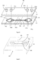
- a prior art microfluidic device 10 comprises two fluidic parts 21 and 22, part 21 also being called a cover plate and part 22 also being called a separator.
- the separator and the cover plate are substantially flat, and assembled together so as to produce fluid channels.
- the separator is microthermally bonded to the cover plate to produce a device 10 capable of being observed by an optical analysis device such as a microscope.
- the device consists of three inlet orifices 30a, 30b, 30c and three outlet orifices 60a, 60b, 60c connected by a rectilinear separation channel 50, 35 mm long, allowing, during operation of the system , cells, particles or molecules to become acoustically concentrated in the channel 70b, the axis of which is identical and in the extension of the axis of the separation channel 50.
- the cells, particles or molecules are acoustically concentrated in the central channel according to their density, size and compressibility.
- the three inlet orifices 30a, 30b, 30c communicate with the separation channel 50 via delivery channels 40a, 40b, 40c respectively.
- the separation channel 50 also communicates with the three exit orifices 60a, 60b, 60c, through routing channels, respectively 70a, 70b, 70c.
- the separator 22 comprises a 1 mm thick glass plate coated with a layer of chromium and a layer of photosensitive resin. After development of the photosensitive layer, the glass is etched with hydrofluoric acid (HF) producing transport channels and separation with a depth of 125 ⁇ m, a lower width, at the bottom of the channels, of 375 ⁇ m, and an upper width of 625 ⁇ m in the plane of the separator in contact with the cover plate.
- HF hydrofluoric acid
- the cover plate 21 is drilled to make the inlet and outlet orifices and then thermally bonded with the separator in order to make a sealed assembly.
- the routing channels of the inlet orifices 40a, 40b, 40c have an angle of respectively 45°, 0° and minus 45° with respect to the separation channel in the plane of the separator, so as to slow down the flow of fluids from the delivery channels having an angle of 45 ° or -45 °, 40a, 40c, relative to the separation channel and thus promote the appearance of a laminar flow in the separation channel.
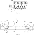
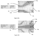
- the typical profile of a routing or separation channel is shown on the figure 2b .
- the channels have a D-shape in the plane perpendicular to the axis of the channel considered, the greatest width being located in the plane in contact with the cover plate when the device is assembled. They thus have a lower width “Lmin”, at the bottom of the channels, a higher width “Lmax” in the plane of the separator in contact with the cover plate when the device is assembled as well as a depth “P”.
- This prior art device is capable of implementing methods for processing biological samples by acoustophoresis.
- all or part of the biological sample to be treated is introduced into the inlet orifices 30a and 30c of the device 10.
- a buffer solution is introduced into the inlet orifice 30b, the buffer and the sample being introduced at respective flow rates capable of generating a laminar flow in the separation channel.
- An ultrasonic transducer, such as a piezoelectric transducer, attached to the separation channel is then activated by a control signal, so as to perform a step of separating said biological sample by acoustophoresis.
- This separation makes it possible to promote the concentration of non-specific particles in the sample, in the outlet orifice 60b of said acoustophoresis device.
- the decomplexified sample being obtained in the outlet orifices 60a and 60c.
- the concentrated sample being obtained in the outlet port 60b.
- microfluidic devices allowing the treatment of biological samples by acoustophoresis. These various devices are also capable of implementing the method according to the invention in an advantageous manner. These devices are particularly interesting to implement with the method according to the invention because they make it possible to achieve higher sample preparation rates than devices of the prior art while ensuring a rate of decomplexification equal to or greater than those observed in the prior art for biological samples such as primary blood samples or sterile bodily fluids incubated in culture medium.
- the inlet orifices and the shape of the routing channels communicating with the inlet orifices can advantageously be optimized in order to accept sedimentation of non-specific particles, aggregates (of lipids or erythrocytes) or debris at the inlets of the device microfluidics without the risk of clogging the channels of the device.
- the part of each conveyance channel facing each inlet orifice capable of receiving the biological sample may have a cavity of greater depth than the general depth of the conveyance channel.
- the cavity facing the inlet orifice is two to three times deeper than the delivery channel connected to said orifice. This cavity makes it possible to create a zone of slowed or zero speed of the sample introduced, favoring the sedimentation of non-specific particles.
- the device thus formed has better tolerance to clogging related to the introduction of non-specific particles of large size and density.
- the separator can be made of silicon, ceramic or glass, the channels being obtained by chemical or physical etching (e.g. sandblasting).
- the separator can also be made of a flexible, thin polymeric material such as polydimethylsiloxane (PDMS), Polypropylene or a Polymer/Silicone bicompound (for example a Polystyrene with a flexible film of silicone or PDMS in order to ensure a coupling without air of the piezoelectric transducers on the wall of the device), the channels then being obtained by molding.
- PDMS polydimethylsiloxane
- Polypropylene Polypropylene
- a Polymer/Silicone bicompound for example a Polystyrene with a flexible film of silicone or PDMS in order to ensure a coupling without air of the piezoelectric transducers on the wall of the device
- each orifice, inlet or outlet can form a reservoir so as to be able to carry out operations for storing a sample as well as depositing and pipetting operations.
- a sample incubation step can also be carried out.
- an orifice can be made of a transparent or translucent material, so as to be able to directly read the optical density of the sample it contains.
- each device can be used alone or in parallel so as to be able to process a volume of biological sample at a higher rate. Indeed, if the rate of introduction of fluids into the same separation channel is increased, the rate of decomplexification of the sample can decrease rapidly, the particles not having time to be separated by the acoustic wave due to too short a residence time in the device.
- the excitation amplitude (of the control signal) of the transducer(s) ) piezoelectric(s) necessary for a good separation of the particles will have to be much greater since the resonant frequency will be reduced and consequently the radiation pressure on the particles to be focused in the center of the separation channel.
- the ultrasonic transducer by exciting the ultrasonic transducer at a higher amplitude, it can cause local heating in the separation channel. This heating is undesirable because it can cause degradation of the device as well as of the viability of the particles, cells, or molecules of interest present in the separation channel.
- this heating can cause a change in the density of the buffer used, which can modify the propagation of the acoustic waves in the channel and disturb the separation step.
- the devices used alone or in parallel make it possible to obtain separation/decomplexification rates equal to or greater than those of the prior art while guaranteeing the viability of the particles, cells, or molecules of interest treated.
- the separation channels of the various devices have a length that can be between 35mm and 80mm.
- the lower widths of the separation channel are for example between 300 ⁇ m and 375 ⁇ m, the upper widths are for example between 550 ⁇ m and 625 ⁇ m.
- the depth of the separation channel can be between 100 ⁇ m and 150 ⁇ m, preferably 125 ⁇ m.
- the various devices are suitable for use with control signals from the ultrasonic transducer(s) attached(s) having a frequency of between 300 kHz and 10 MHz, preferably 1.3 MHz, alternatively 1.44 MHz for the creation of a single pressure node in the center of the channel.
- the amplitude of the control signal is between 0.1V and 100V, preferably 38V.
- a cooling device attached to the ultrasonic transducer(s) to prevent degradation of the device and/or damage to the viability of the particles, cells, or molecules present in the separation channel.
- Peltier blocks or fans can constitute such cooling devices.
- the cooling device is temperature-controlled in order to regulate the temperature close to the ultrasonic transducer.
- the channels for conveying the inlet orifices used for the introduction of the biological sample have an angle of between 30 and 60°, preferably 45° with respect to the separation channel in the plane of the separator. This angle can easily be adapted by those skilled in the art so as to more or less slow down the rate of introduction of the fluid into the separation channel, and thus ensure the appearance of a laminar flow of the fluids in this channel.
- These delivery channels are called side channels because they allow the fluid to be introduced in the direction of the walls of the separation channel.
- the delivery channels to the outlet orifices used to recover or reintroduce the decomplexified sample have an angle of between 30 and 60°, preferably 45° with respect to the separation channel in the plane of the separator. This angle can easily be adapted by those skilled in the art so as to more or less slow down the rate of suction of the fluid from the separation channel, and thus ensure the appearance of a laminar flow of the fluids in this channel.
- These transport channels are also called side channels because they make it possible to suck up the fluid circulating along the walls of the separation channel.
- Routing channels whose axis(es) is (are) identical to the axis of the separation channel are called central channels. These channels transport the concentrated sample.
- the sections of the routing channels of the inlet and outlet orifices can be adapted.
- the sections of the transport channels of the lateral outlet orifices in which we find the decomplexified sample
- the section of the transport channel of the central outlet orifice in which we find a maximum of non-specific particles
- the resonance is not very effective (because there are no longer any side walls at the branch) for a short transient time. This leads to a partial loss of focus of the non-specific particles.
- the adjustment of the ratios of the sections between the channels 70a or 70c and 70b can thus make it possible to minimize the losses of microorganisms or to improve the rate of concentration of non-specific particles or debris in the central conveying channel 70b.
- FIG. 4 A first embodiment of a device is shown in the figures 4 and 5a .
- This device 200 comprises two inlet orifices 230a, 230b, a separation channel 250 and at least two outlet orifices 260a, 260b.
- the device 200 comprises two fluidic parts, a separator 222 and a cover plate 221, which are substantially planar. These two parts are assembled hermetically.
- the inlets open to the separation channel, while the separation channel opens to the outlets through routing channels.
- the separation channel 250 opens towards the orifice 230a via the transport channel 240a, towards the orifice 230b via the transport channel 240b, towards the orifice 260a via the transport channel 270a, towards the port 260b via delivery channel 270b.
- the device is arranged so that at least one ultrasound transducer can be integrated into or attached to a wall of said separation channel.
- the ultrasonic transducer thus integrated or attached is capable of transmitting mechanical oscillations in multiple acoustic waves which can act on the content of the separation channel.
- the device comprises two recesses 290a, 290b, made along the separation channel 250, in the separator 222, and each capable of receiving an ultrasound transducer.
- This embodiment makes it possible to obtain a stationary wave in a separator made of a material that is not very reflective to acoustic waves, the material being flexible and thin, such as plastic materials, polymers, silicones.
- a silicone preferably used is polydimethylsiloxane (PDMS).
- PDMS polydimethylsiloxane
- each ultrasonic transducer comprises an adapter 1 ⁇ 4 wave plate whose acoustic impedance is calculated to minimize the energy losses, and therefore the heating, between the ultrasonic transducer and the walls of the device.
- This resin blade covering the piezoelectric transducer(s) (made by casting and polymerization), is defined to have an intermediate acoustic impedance between the acoustic impedance of the material used for the realization of the device, and the impedance acoustics of the piezoelectric transducer(s).
- the cover plate 221 is made of Polydimethylsiloxane (PDMS) or a molded plastic material such as Polycarbonate (PC), poly(methyl methacrylate) (PMMA), polypropylene (PP), PolyStyrene (PS), Acrylonitrile butadiene styrene ( ABS), Cyclic Olefin Polymer (COC), Cyclic Olefin Polymer (COP), Polyoxymethylene (POM).
- PC Polycarbonate
- PMMA poly(methyl methacrylate)
- PP polypropylene
- PS PolyStyrene
- ABS Acrylonitrile butadiene styrene
- COC Cyclic Olefin Polymer
- COP Cyclic Olefin Polymer
- POM Polyoxymethylene
- This device 200 is capable of implementing methods for preparing biological samples by acoustophoresis.
- all or part of the biological sample to be treated is introduced into the inlet 230a of the device 200.
- a buffer solution is introduced into the inlet 230b, the buffer and the sample being introduced at respective flow rates capable of generating a laminar flow in the separation channel.
- An ultrasonic transducer such as a piezoelectric transducer, attached to the separation channel is then activated by a control signal, so as to perform a step of separating said biological sample by acoustophoresis.
- This separation makes it possible to promote the concentration of non-specific particles, such as formed elements of blood, present in the sample, in the outlet orifice 260b of said acoustophoresis device.
- the decomplexified sample being obtained in the outlet orifice 260a.
- the non-specific particles are thus transferred into the buffer solution introduced into the inlet 230b.
- the concentrated sample being thus obtained in the outlet orifice 260b.
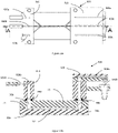
- the inlet 230a here has a frustoconical shape but can also be cylindrical depending on the means of introduction chosen.
- the shape of the routing channel 240a, facing the orifice 230a is modified so as to include a cavity 241a of greater depth than the general depth of the routing channel 240a.
- This cavity thus has a depth P2 with P2 of between two and three times the depth P of the transport channel.
- This cavity makes it possible to create a zone of slowed or zero speed (Z) of the introduced sample, favoring the sedimentation of the non-specific particles contained in the sample.
- the device thus formed has a better tolerance to clogging related to the introduction of non-specific particles of large size and density.
- a second embodiment of a device 300 comprising two fluidic parts, a separator 322 and a cover plate (not shown), these two parts being substantially planar. These two parts are assembled hermetically. Channels are made in the separator 322.
- the device 300 comprises two inlet orifices 330a, 330b, in fluid communication with at least one separation channel 350 by means of delivery channels 340a, 340c respectively for the orifice 330a and 340b for port 330b.
- the separation channel 350 is also in fluid communication with two outlet orifices 360a, 360b, through delivery channels, respectively 370a and 370c for the orifice 360a and 370b for the orifice 360b.
- This configuration makes it possible to simplify the fluidic connection because it has only two inlet orifices and two outlet orifices. Similarly, the collection of the decomplexified sample can be carried out in an outlet port or a single collection tube.
- the routing channels 370a and 370c towards the outlet orifice 360a being directly connected by etching the channels on the device, the balancing of the pressure drops at the level of the branching of the routing channels towards outlets is significantly improved. A minimal difference in pressure drop (linked to a difference in the connection of the output tubes on the device) which can lead to a deviation of the focus and thus a significant degradation of the decomplexification performance.
- the device 300 is arranged so that an ultrasonic transducer, not shown, can be integrated into or attached to a wall of said separation channel 350.
- the ultrasonic transducer thus integrated or attached is capable of transmitting mechanical oscillations in multiple acoustic waves which can act on the content of the separation channel and generate a standing acoustic wave there.
- An alternating current generator associated with a signal amplifier, not shown, can be electrically connected to the transducer in order to generate a transducer control signal whose frequency, waveform and amplitude are known.
- the separator 322 is produced in a 1 mm thick glass plate coated with a layer of chromium and a layer of photosensitive resin. After development of the photosensitive layer, the glass is etched with hydrofluoric acid (HF).
- HF hydrofluoric acid
- the routing channels 340a and 340c, 370a and 370c have a depth P of 125 ⁇ m, a lower width Lmin, at the bottom of the channels, of 300 ⁇ m, and a upper width Lmax of 550 ⁇ m in the plane of the separator in contact with the cover plate.
- the transport channels 340b and 370b as well as the separation channel 350 have a depth P of 125 ⁇ m, a lower width Lmin, at the bottom of the channels, of 375 ⁇ m, and an upper width Lmax of 625 ⁇ m in the plane of the separator in contact with the cover plate.
- the cover plate is drilled to make the inlet and outlet orifices and then thermally bonded with the separator in order to make a tight assembly.
- the routing channels of the inlet orifices 340a, 340b present an angle of respectively 45°, 0° and minus 45° with respect to the separation channel 350 in the plane of the separator, so as to slow the flow of the fluids from the delivery channels having an angle of 45° or -45°, 340a, 340b, with respect to the separation channel.
- the rectilinear separation channel 350 has a length of 80 mm, allowing the cells, particles or molecules to become acoustically concentrated in the transport channel 370b during operation of the system.
- the axis of the transport channel 370b is identical to the axis of the separation channel. Cells, particles or molecules are acoustically concentrated in the central channel 370b, depending on their density, size and compressibility.
- the separator 322 of the device 300 comprises two recesses (not shown) made along the separation channel 350, and each capable of receiving an ultrasound transducer (not shown).
- This embodiment makes it possible to obtain a standing wave in the separator 322 if the latter is made of a material that is not very reflective to acoustic waves, the material being flexible and thin, such as plastic materials, polymers, silicones.
- a silicone preferably used is polydimethylsiloxane (PDMS).
- PDMS polydimethylsiloxane
- each ultrasonic transducer comprises an adapter 1 ⁇ 4 wave plate whose acoustic impedance is calculated to minimize the energy losses, and therefore the heating, between the ultrasonic transducer and the walls of the device.
- the cover plate (not shown) is made of PDMS or a molded plastic material such as Polycarbonate (PC), poly(methyl methacrylate) (PMMA), polypropylene (PP), PolyStyrene (PS), Acrylonitrile butadiene styrene ( ABS), Cyclic Olefin Polymer (COC), Cyclic Olefin Polymer (COP), Polyoxymethylene (POM).
- PC Polycarbonate
- PMMA poly(methyl methacrylate)
- PP polypropylene
- PS PolyStyrene
- ABS Acrylonitrile butadiene styrene
- COC Cyclic Olefin Polymer
- COP Cyclic Olefin Polymer
- POM Polyoxymethylene
- This device 300 is capable of implementing methods for preparing biological samples by acoustophoresis. For this, all or part of the biological sample to be treated is introduced into the inlet 330a of the device 300. A buffer solution is introduced into the inlet 330b, the buffer and the sample being introduced at respective flow rates capable of generating a laminar flow in the separation channel. An ultrasonic transducer, such as a piezoelectric transducer, attached to the separation channel is then activated by a control signal, so as to perform a step of separating said biological sample by acoustophoresis. This separation makes it possible to promote the concentration of non-specific particles, such as formed elements of blood, present in the sample, in the outlet orifice 360b of said acoustophoresis device. The decomplexified sample being obtained in the outlet orifice 360a. The concentrated sample being obtained in the outlet port 360b.
- a device 400 comprising two fluidic parts, a separator 422 and a cover plate (not shown), these two parts being substantially planar. These two parts are assembled hermetically. Fluidic channels are made in the separator 422.
- the device 400 comprises two inlets 430a, 430b, in fluidic communication with at least one separation channel 450 by means of routing channels 440a, 440c respectively, for the orifice 430a and 440b for orifice 430b.
- the separation channel 450 is also in fluid communication with three outlet orifices 460a, 460b, 460c, through delivery channels, respectively 470a and 470c for the orifice 460a, 470b and 470d for the orifice 460c; 470b, 470f and 470e for outlet port 460b.
- the device 400 is arranged so that an ultrasonic transducer, not shown, can be integrated into or attached to a wall of said separation channel 450.
- the ultrasonic transducer thus integrated or attached is capable of transmitting mechanical oscillations in multiple acoustic waves which can act on the content of the separation channel and generate a standing acoustic wave there.
- a function generator associated with a signal amplifier can be electrically connected to the transducer in order to generate a transducer control signal whose frequency, waveform and amplitude are known.
- the transport channel 470b placed in the extension of the separation channel 450, allows the realization of a second stage of separation of the non-specific particles which can remain in the biological sample.
- the separator 422 is made of a 1 mm thick glass plate coated with a layer of chromium and a layer of photosensitive resin. After development of the photosensitive layer, the glass is etched with hydrofluoric acid (HF).
- the routing channels 440a, 440c, 470a, 470c, 470e and 470f have a depth P of 125 ⁇ m, a lower width Lmin, at the bottom of the channels, of 300 ⁇ m, and a width higher Lmax of 550 ⁇ m in the plane of the separator in contact with the cover plate.
- the transport channels 440b, 470b and 470d as well as the separation channel 450 have a depth P of 125 ⁇ m, a lower width Lmin, at the bottom of the channels, of 375 ⁇ m, and an upper width Lmax of 625 ⁇ m in the plane of the separator in contact with the cover plate.
- the cover plate is drilled to make the inlet and outlet orifices and then thermally bonded with the separator in order to make a tight assembly.
- the routing channels of the inlet orifices 440a, 440b, 440c present an angle of respectively 45°, 0° and minus 45° with respect to the separation channel 450 in the plane of the separator, so as to slow the flow fluids from the delivery channels having an angle of 45 ° or - 45 °, 440a, 440c, relative to the separation channel.
- the rectilinear separation channel 450 has a length of 80 mm, allowing, during operation of the system, the cells, particles or molecules to become acoustically concentrated in the transport channel 470b then 470d, the axes of which are identical to the axis of the separation channel.
- the separator 422 of the device 400 comprises two recesses (not shown) made along the separation channel 450, and each capable of receiving an ultrasound transducer (not shown).
- This embodiment makes it possible to obtain a stationary wave in the separator 422 if the latter is made of a material that is not very reflective to acoustic waves, the material being flexible and thin, such as plastic materials, polymers, silicones.
- a silicone preferably used is polydimethylsiloxane (PDMS).
- each ultrasonic transducer comprises an adapter 1 ⁇ 4 wave plate whose acoustic impedance is calculated to minimize the energy losses, and therefore the heating, between the ultrasonic transducer and the walls of the device.
- the cover plate (not shown) is made of PDMS or a molded plastic material such as Polycarbonate (PC), poly(methyl methacrylate) (PMMA), polypropylene (PP), PolyStyrene (PS), Acrylonitrile butadiene styrene ( ABS), Cyclic Olefin Polymer (COC), Cyclic Olefin Polymer (COP), Polyoxymethylene (POM).
- PC Polycarbonate
- PMMA poly(methyl methacrylate)
- PP polypropylene
- PS PolyStyrene
- ABS Acrylonitrile butadiene styrene
- COC Cyclic Olefin Polymer
- COP Cyclic Olefin Polymer
- POM Polyoxymethylene
- This device 400 is capable of implementing methods for preparing biological samples by acoustophoresis. For this, all or part of the biological sample to be treated is introduced into the inlet 430a of the device 400. A buffer solution is introduced into the inlet 430b, the buffer and the sample being introduced at respective flow rates capable of generating a laminar flow in the separation channel. A transducer ultrasound, such as a piezoelectric transducer, attached to the separation channel is then activated by a control signal, so as to perform a step of separating said biological sample by acoustophoresis. This separation makes it possible to promote the concentration of non-specific particles, such as formed elements of blood, present in the sample, in the conveying channel 470b of said acoustophoresis device.
- the decomplexified sample is obtained in the outlet orifice 460a.
- a second step of separation of said biological sample by acoustophoresis is carried out on the part resulting from the first separation, the concentrated sample, in the channel 470b. This separation makes it possible to promote the concentration of non-specific particles, such as formed elements of blood, present in the concentrated sample, in the outlet orifice 460c of said acoustophoresis device.
- the decomplexed sample a second time is obtained in the outlet port 460b.
- the collection and mixing of the decomplexified samples from the outlet orifices 460a and 460b make it possible to increase the collection yield of the microorganisms present in the biological sample.
- the microorganisms entrained with the non-specific particles during the first separation in the channel 470b are likely to be separated by acoustophoresis in this channel 470b and thus to be able to be collected following this second separation in the orifice 460b.
- the relative position and the length of the second separation channel 470b with respect to the main separation channel 450 is chosen according to the applications, the performances and the desired flow rates.
- the invention relates to a device 1300 comprising two fluidic parts, a separator 1322 and a cover plate (not shown), these two parts being substantially planar. These two parts are assembled hermetically. Channels are made in the separator 1322.
- the device 1300 comprises two inlet ports 1330a, 1330b, in fluid communication with a first separation channel 1350 via delivery channels respectively 1340a, 1340c for the port 1330a and 1340b for port 1330b.
- Separation channel 1350 is in fluid communication with outlet port 1360b, through delivery channel 1370b.
- Separation channel 1350 is also in fluid communication with a second separation channel 1350' through two routing channels 1370a and 1370c.
- the second separation channel 1350' is in fluid communication with an exit port 1360b', through a delivery channel 1370b' and in fluid communication with an exit port 1360a, through two delivery channels 1370a' and 1370c'.
- Device 1300 also includes an inlet port 1330b', in fluid communication with second separation channel 1350' via delivery channel 1340b'.
- the device 1300 is arranged so that one or more ultrasonic transducer(s), not shown, can be integrated into or attached to a wall of said separation channels 1350 and 1350'.
- the ultrasonic transducer(s) thus integrated or attached is (are) capable of transmitting mechanical oscillations in multiple acoustic waves which can act on the content of the separation channels and generate a standing acoustic wave.
- An alternating current generator associated with a signal amplifier, not shown, can be electrically connected to the transducer(s) in order to generate a control signal whose frequency, waveform and amplitude are known.
- the decomplexified sample is injected into the second separation channel 1350' via the channels 1370a and 1370c.
- the decomplexified sample is then separated a second time from the non-specific particles which may still be present, these being found in the orifice 1360b'.
- the decomplexed sample a second time is obtained in the outlet port 1360a.
- the separator 1322 is made from a 1 mm thick glass plate coated with a layer of chromium and a layer of photosensitive resin. After development of the photosensitive layer, the glass is etched with hydrofluoric acid (HF).
- the routing channels 1340a and 1340c, 1370a, 1370c, 1370a' and 1370c' have a depth P of 125 ⁇ m, a lower width Lmin, at the bottom of the channels, of 300 ⁇ m, and an upper width Lmax of 550 ⁇ m in the plane of the separator in contact with the cover plate.
- the transport channels 1340b, 1340b', 1370b and 1370b' as well as the separation channels 1350 and 1350' have a depth P of 125 ⁇ m, a lower width Lmin, at the bottom of the channels, of 375 ⁇ m, and a greater width Lmax of 625 ⁇ m in the plane of the separator in contact with the cover plate.
- the cover plate is drilled to make the inlet and outlet orifices then thermally bonded with the separator in order to achieve a tight assembly.
- the routing channels of the inlet orifices 1340a, 1340b present an angle of respectively 45°, 0° and minus 45° with respect to the separation channel 1350 in the plane of the separator, so as to slow the flow of fluids coming from transport channels having an angle of 45° or -45°, 1340a, 1340c, with respect to the separation channel 1350.
- the straight separation channel 1350 has a length of 19.5 mm, allowing the cells, particles or molecules from becoming acoustically concentrated in the routing channel 1370b during system operation.
- the axis of the transport channel 1370b is identical to the axis of the separation channel.
- the routing channels 1370a, 1370b, 1340b' have an angle of respectively 45°, 0° and minus 45° relative to the separation channel 1350' in the plane of the separator, so as to slow down the flow of fluids coming from the transport channels having an angle of 45° or -45°, 1340a, 1340c, with respect to the second separation channel 1350'.
- the second straight separation channel 1350' is 19.5 mm long, allowing cells, particles or molecules to become acoustically concentrated in the transport channel 1370b' during system operation.
- the axis of the transport channel 1370b' is identical to the axis of the separation channel 1350'.
- the cells, particles or molecules are acoustically concentrated in the central channel 1370b', according to their density, their size and their compressibility.
- the separator 1322 of the device 1300 comprises four recesses (not shown) made along the separation channels 1350 and 1350', and each capable of receiving an ultrasound transducer (not shown).
- This embodiment makes it possible to obtain a stationary wave in the separator 1322 if the latter is made of a material that is not very reflective to acoustic waves, the material being flexible and thin, such as plastics, polymers, silicones.
- a silicone preferably used is polydimethylsiloxane (PDMS).
- each ultrasonic transducer comprises an adapter 1 ⁇ 4 wave plate whose acoustic impedance is calculated to minimize the energy losses, and therefore the heating, between the ultrasonic transducer and the walls of the device.
- the cover plate (not shown) is made of PDMS or a molded plastic material such as Polycarbonate (PC), poly(methyl methacrylate) (PMMA), polypropylene (PP), Polystyrene (PS), Acrylonitrile butadiene styrene (ABS), Cyclic Olefin Polymer (COC), Cyclic Olefin Polymer (COP), Polyoxymethylene (POM).
- PC Polycarbonate
- PMMA poly(methyl methacrylate)
- PP polypropylene
- PS Polystyrene
- ABS Acrylonitrile butadiene styrene
- COC Cyclic Olefin Polymer
- COP Cyclic Olefin Polymer
- POM Polyoxymethylene
- This device 1300 is capable of implementing methods for preparing biological samples by acoustophoresis such as the method according to the invention.
- all or part of the biological sample to be treated is introduced into the inlet 1330a of the device 1300.
- a buffer solution is introduced into the inlet orifices 1330b and 1330b', the buffers and the sample being introduced at respective flow rates capable of generating a laminar flow in the separation channels 1350 and 1350'.
- One or more ultrasonic transducer(s), attached to the separation channels is (are) then activated by a control signal, so as to carry out two successive steps of separation of said biological sample by acoustophoresis.
- This separation makes it possible to promote a first time the concentration of the non-specific particles, present in the sample, in the outlet orifice 1360b. Following this first separation, a second separation makes it possible to promote a second time the concentration of non-specific particles, such as food debris still present in the decomplexified sample coming from channels 1370a and 1370c in the outlet orifice 1360b'.
- the decomplexed sample a second time and exhibiting improved purity being obtained in the outlet port 1360a.
- the relative position and length of the second separation channel 1350' vis-à-vis the main separation channel 1350' is chosen according to the applications, the performances and the desired flow rates.
- two buffer solutions of different type or density are introduced into the inlet orifices 1330b and 1330b'.
- the invention also relates to a device 1400 comprising two fluidic parts, a separator 1422 and a cover plate (not shown), these two parts being substantially planar. These two parts are assembled hermetically. Fluidic channels are made in the separator 1422.
- the device 1400 comprises two inlet ports 1430a, 1430b, in fluid communication with a first separation channel 1450 by means of routing channels 1440a, 1440c respectively, for the orifice 1430a and 1440b for port 1430b.
- First separation channel 1450 is also in fluid communication with exit port 1460a, through delivery channels 1470a and 1470c.
- the first separation channel 1450 is finally in fluid communication with a second separation channel 1450', through transport channels 1440a' and 1440c'.
- Device 1400 also includes an inlet port 1430b', in fluid communication with second separation channel 1450 through delivery channel 1440b'.
- the second separation channel 1450' is also in fluid communication with two outlet orifices 1460b, 1460c, by means of delivery channels, respectively 1470d for the orifice 1460c; 1470e and 1470f for outlet port 1460b.
- the device 1400 is arranged so that one or more ultrasonic transducer(s), not shown, can be integrated into or attached to a wall of said separation channels 1450 and 1450'.
- the ultrasonic transducer(s) thus integrated or attached is (are) capable of transmitting mechanical oscillations in multiple acoustic waves which can act on the content of the separation channels and generate a standing acoustic wave.
- An alternating current generator associated with a signal amplifier, not shown, can be electrically connected to the transducer(s) in order to generate a control signal whose frequency, waveform and amplitude are known.
- the separator 1422 is produced in a 1 mm thick glass plate coated with a layer of chromium and a layer of photosensitive resin. After development of the photosensitive layer, the glass is etched with hydrofluoric acid (HF).
- the routing channels 1440a, 1440c, 1470a, 1470c, 1470e and 1470f have a depth P of 125 ⁇ m, a lower width Lmin, at the bottom of the channels, of 300 ⁇ m, and an upper width Lmax of 550 ⁇ m in the plane of the channel. separator in contact with the cover plate.
- the transport channels 1440b, 1470b and 1470d as well as the separation channels 1450 and 1450' have a depth P of 125 ⁇ m, a lower width Lmin, at the bottom of the channels, of 375 ⁇ m, and an upper width Lmax of 625 ⁇ m in the plane of the separator in contact with the cover plate.
- the cover plate is drilled to make the inlet and outlet orifices and then thermally bonded with the separator in order to make a tight assembly.
- the delivery channels 1440a, 1440c have an angle of respectively 45° and minus 45° relative to the separation channel 1450 in the plane of the separator, so as to slow down the flow of fluids coming from these delivery channels.
- the delivery channels 1440a', 1440c' have an angle of respectively 45° and minus 45° with respect to the separation channel 1450' in the plane of the separator.
- the rectilinear separation channels 1450 and 1450' have a length of 22.5 mm, allowing, during operation of the system, the cells, particles or molecules to become acoustically concentrated in the routing channel 1470b then 1470d, whose axes are identical to the axes of the separation channels.
- the separator 1422 of the device 1400 comprises four recesses (not shown) made along the separation channels 1450 and 1450', and each capable of receiving an ultrasound transducer (not shown).
- This embodiment makes it possible to obtain a stationary wave in the separator 1422 if the latter is made of a material that is not very reflective to acoustic waves, the material being flexible and thin, such as plastic materials, polymers, silicones.
- a silicone preferably used is polydimethylsiloxane (PDMS).
- each ultrasonic transducer comprises an adapter 1 ⁇ 4 wave plate whose acoustic impedance is calculated to minimize the energy losses, and therefore the heating, between the ultrasonic transducer and the walls of the device.
- the cover plate (not shown) is made of PDMS or a molded plastic material such as Polycarbonate (PC), poly(methyl methacrylate) (PMMA), polypropylene (PP), Polystyrene (PS), Acrylonitrile butadiene styrene ( ABS), Cyclic Olefin Polymer (COC), Cyclic Olefin Polymer (COP), Polyoxymethylene (POM).
- PC Polycarbonate
- PMMA poly(methyl methacrylate)
- PP polypropylene
- PS Polystyrene
- ABS Acrylonitrile butadiene styrene
- COC Cyclic Olefin Polymer
- COP Cyclic Olefin Polymer
- POM Polyoxymethylene
- This device 1400 is capable of implementing methods for preparing biological samples by acoustophoresis such as the method according to the invention. For this, all or part of the biological sample to be treated is introduced into the inlet 1430a of the device 1400. A buffer solution is introduced into the inlet 1430b, the buffer and the sample being introduced at respective flow rates capable of generating a laminar flow in the separation channel 1450. An ultrasonic transducer, such as a piezoelectric transducer, attached to the separation channel 1450 is then activated by a control signal, so as to carry out a step of separation of said biological sample by acoustophoresis.
- a control signal so as to carry out a step of separation of said biological sample by acoustophoresis.
- This separation makes it possible to promote the concentration of non-specific particles, present in the sample, in the transport channel 1470b of said acoustophoresis device.
- the decomplexified sample is obtained in the outlet port 1460a.
- a second stage of separation of said sample concentrated by acoustophoresis is also carried out on the part resulting from the first separation in channel 1450'.
- a second clean buffer is introduced simultaneously into the inlet orifice 1430b' in order to extract the residual species of interest still present in the concentrated sample.
- the collection and mixing of the decomplexified samples from the outlet orifices 1460a and 1460b make it possible to increase the collection yield of the microorganisms initially present in the biological sample. Indeed, the microorganisms entrained with the non-specific particles during the first separation towards the channel 1450' via the channels 1440a' and 1440c' are likely to be separated by acoustophoresis in this channel 1450' and thus to be able to be collected following this second separation in port 1460b. The extraction yield of the microorganisms is thus improved.
- the relative position and length of the second separation channel 1450' vis-à-vis the main separation channel 1450' is chosen according to the applications, the performances and the desired flow rates.
- two buffer solutions of different type or density are introduced into the inlet orifices 1430b and 1430b'.
- the device may comprise, around the conveying channel towards an outlet orifice containing the decomplexified sample, mobile magnet supports allowing the capture of the sample placed in presence of magnetic particles such as magnetic silica.
- mobile magnet supports As shown on the figure 7a at the output of the device 300, close to the orifice 360a, two mobile magnet supports 2000 are arranged.
- the magnets thus arranged on either side of the conveyance channel towards the outlet orifice 360a make it possible to capture microorganisms in continuous flow by displacement of magnetic silica particles 2100 perpendicular to the flow of the decomplexified sample.
- the movement M of the magnet supports takes place, for example, perpendicular to the channel and alternately between the two supports in order to promote mixing of the sample and the particles.
- the device may comprise, around the channel for conveying to an outlet orifice containing the decomplexified sample, Di ElectroPhoresis (DEP) electrodes deposited on the surface of the device. at the outlet orifice.
- Di ElectroPhoresis (DEP) electrodes deposited on the surface of the device. at the outlet orifice.
- two Di ElectroPhoresis (DEP) electrodes 3000 are arranged in order to allow the performance of a specific capture step.
- These electrodes can be either functionalized with capture antigens in the case of a capture on a panel of species sought, or not functionalized then using only the well-known properties of capture by the charge of the DEP technique.
- the identification of the captured species(s) of interest can be confirmed in both cases or carried out for example by Raman 3100 identification.
- a sixth device 500 comprising two fluidic parts, a separator 522 and a cover plate 521, these two parts being substantially planar. These two parts are assembled hermetically. Fluid channels are made in separator 522.
- Device 500 includes two inlets 530a, 530b, made in cover plate 521, in fluid communication with at least one separator channel 550 through delivery channels respectively 540a, 540c, for the orifice 530a and 540b for the orifice 530b.
- the separation channel 550 is also in fluid communication with two outlet orifices 560a, 560b, through delivery channels, respectively 570a and 570c for the orifice 560a, 570b for the orifice 560b.
- the inlet and outlet orifices form reservoirs so as to be able to carry out operations of depositing a sample to be decomplexified by pipetting and of the buffer solution as well as operations of connection to a pressurization or vacuum system controlled and regulated on the flow measurement and making it possible to control in a reproducible way the introduction and the flow of the biological samples and the buffer in the separation channel.
- the device 500 is arranged so that an ultrasonic transducer, not shown, can be integrated into or attached to a wall of said separation channel 550.
- the ultrasonic transducer thus integrated or attached is capable of transmitting mechanical oscillations in multiple acoustic waves which can act on the content of the separation channel and generate a standing acoustic wave there.
- An alternating current generator not shown, can be electrically connected to the transducer in order to generate a transducer control signal whose frequency, waveform and amplitude are known.
- the separator 522 is made of a 1 mm thick glass plate coated with a layer of chromium and a layer of photosensitive resin. After development of the photosensitive layer, the glass is etched with hydrofluoric acid (HF).
- HF hydrofluoric acid
- the transport channels 540a and 540c, 570a, 570c have a depth P of 125 ⁇ m, a lower width Lmin, at the bottom of the channels, of 300 ⁇ m, and an upper width Lmax of 550 ⁇ m in the plane of the separator in contact with the cover plate.
- the transport channels 540b, 570b as well as the separation channel 550 have a depth P of 125 ⁇ m, a lower width Lmin, at the bottom of the channels, of 375 ⁇ m, and an upper width Lmax of 625 ⁇ m in the plane of the separator in contact with the cover plate.
- the cover plate is drilled to make the inlet and outlet orifices and then thermally bonded with the separator in order to make a tight assembly.
- the inlet port routing channels (540a, 540b, 540c) are angled 45°, 0°, and minus 45°, respectively, with respect to the separation channel 550 in the plane of the separator, so as to slow down the flow of fluids from the delivery channels having an angle of 45° or -45°, 540a, 540c, with respect to the separation channel.
- Straight separation channel 550 is 80 mm long, allowing cells, particles or molecules to become acoustically concentrated in transport channel 570b during system operation.
- the axis of the transport channel 570b is identical to the axis of the separation channel 550.
- the separator 522 of the device 500 comprises two recesses, 590a, 590b, made along the separation channel 550, and each capable of receiving an ultrasound transducer (not shown).
- This embodiment makes it possible to obtain a stationary wave in the separator 522 if the latter is made of a material that is not very reflective to acoustic waves, the material being flexible and thin, such as plastic materials, polymers, silicones.
- a silicone preferably used is polydimethylsiloxane (PDMS).
- PDMS polydimethylsiloxane
- each ultrasonic transducer comprises an adapter 1 ⁇ 4 wave plate whose acoustic impedance is calculated to minimize the energy losses, and therefore the heating, between the ultrasonic transducer and the walls of the device.
- the cover plate (not shown) is made of PDMS or a molded plastic material such as Polycarbonate (PC), poly(methyl methacrylate) (PMMA), polypropylene (PP), PolyStyrene (PS), Acrylonitrile butadiene styrene ( ABS), Cyclic Olefin Polymer (COC), Cyclic Olefin Polymer (COP), Polyoxymethylene (POM).
- PC Polycarbonate
- PMMA poly(methyl methacrylate)
- PP polypropylene
- PS PolyStyrene
- ABS Acrylonitrile butadiene styrene
- COC Cyclic Olefin Polymer
- COP Cyclic Olefin Polymer
- POM Polyoxymethylene
- This device 500 is capable of implementing methods for preparing biological samples by acoustophoresis. For this, all or part of the biological sample to be treated is introduced into the inlet 530a of the device 500. A buffer solution is introduced into the inlet 530b, the buffer and the sample being introduced at respective flow rates able to generate a laminar flow in the separation channel. An ultrasonic transducer, such as a piezoelectric transducer, attached to the separation channel is then activated by a control signal, so as to perform a step of separating said biological sample by acoustophoresis.
- a control signal so as to perform a step of separating said biological sample by acoustophoresis.
- This separation makes it possible to promote the concentration of non-specific particles, such as formed elements of blood, present in the sample, in the outlet orifice 560b of said acoustophoresis device.
- the decomplexified sample being obtained in the outlet orifice 560a.
- the concentrated sample being obtained in the outlet port 560b (trash area).
- the figure 9 presents a support 600 for devices with a device 500 arranged and held on the support.
- This support makes it possible, for example, to process the same biological sample simultaneously on several devices or several different samples simultaneously by connecting one or more reservoir(s) containing the (the) sample(s) such as a syringe to the various inlet orifices of the devices arranged on the support.
- the support may comprise an articulated cover, not shown, making it possible to directly connect the inlet and outlet orifices of the device to pressurizing and/or vacuum means, when the cover is closed.
- This support comprises one or more receiving bases (not shown) for devices, making it possible to place and maintain said devices. The devices can be held in place mechanically or by placing the devices under suction on the receiving base(s).
- Ultrasonic transducers 690 can be arranged in these bases so as to be able to create a standing wave in each of the devices arranged on the support. The transducer being attached to the device when the latter is placed in said base. Alternatively, a single ultrasonic transducer covering several devices can be arranged so as to be able to create a standing wave in each of the devices arranged on the support.
- a reception space 610 makes it possible in particular to attach a heating system (not shown) to at least one of the outlet orifices of the device arranged on the support. Said heating system making it possible to incubate the biological sample treated and contained in at least one of the outlet orifices 560a, 560b.
- the reception space 610 can include a means of measuring the optical density of the sample contained in at least one of the outlet orifices 560a, so as to avoid additional manipulations to carry out this operation.
- the support can be arranged directly on a stirrer or comprise stirring means so as to carry out a step of stirring the biological sample contained in one of the outlet orifices, before, during or following a incubation step.
- This support 600 also makes it possible to arrange and maintain various devices 200, 300, 400, 500, 800, the reception space 610 being able to be easily adapted by those skilled in the art.
- the figure 10 shows a device carrier 700 shown with four devices 500 disposed and held on the carrier.
- This support makes it possible, for example, to process the same biological sample simultaneously on several devices by connecting a reservoir containing the biological sample such as a syringe to the various inlet orifices 530a of the devices placed on the support.
- the support makes it possible to arrange the devices so as to present each of the inlet and outlet orifices aligned on the same axis and according to a defined spacing.
- This spacing can advantageously be equivalent to or multiple to that of the pitch of a microplate known to those skilled in the art.
- the pipetting operations automatic or manual, can be carried out directly in several devices simultaneously, in particular using a pipette or a microplate dispenser.
- This support comprises several receiving pedestals (not shown) for devices, making it possible to place and maintain said devices.
- Ultrasonic transducers (not shown), or a transducer common to several devices, can be arranged in these bases so as to be able to create a standing wave in each of the devices arranged on the support. The transducer being attached to the device when the latter is placed in said base.
- the support 700 can comprise several reception spaces (not shown) making it possible in particular to attach to at least one of the outlet orifices of each of the devices arranged on the support, a heating system (not shown) making it possible to incubate the biological sample treated and contained in at least one of the outlet orifices 560a, 560b.
- each of the reception spaces can include a means for measuring the optical density of the sample contained in at least one of the outlet orifices 560a, so as to avoid additional manipulations to carry out this operation.
- the support 700 can be placed directly on a stirrer or comprise a stirring means so as to achieve a step of stirring the biological sample contained in one of the outlet orifices, before, during or following an incubation step.
- This support 700 also makes it possible to arrange several of the different devices 200, 300, 400, 500, 800 in parallel, the number of receiving bases being able to be easily adapted by those skilled in the art.
- the different devices arranged on the support 700 can be of the same type or of different types.
- a multiplex device 800 comprising three fluidic parts, a separator 822, a cover plate 821 and a base 823, these three parts being substantially planar. These three parts are hermetically assembled. Fluidic channels are made in the separator 822.
- the device 800 comprises two inlet ports 830a, 830b, in fluidic communication with eight separation channels 850, through a network of introduction channels 841, 842, and channels routing.
- the separation channels 850 communicate with the orifice 830a via the network of introduction channels 841 as well as by the routing channels 840a, 840c.
- separation channels 850 communicate with port 830b via inlet channel network 842 as well as delivery channel 840b.
- the separation channels 850 are also in fluid communication with two exit ports 860a, 860b, through a network of suction channels 843, 844 and transport channels.
- separation channels 850 communicate with orifice 860a via network of suction channels 843 as well as delivery channels, 870a, 870c.
- separation channels 850 communicate with orifice 860b via the suction channel network 844 as well as through the transport channel 870b.
- Eight separation channels 850 are shown, each of the channels 850 and associated routing channels forming a fluidic pattern repeated eight times.
- the device 800 is arranged so that an ultrasonic transducer, not shown, can be integrated into or attached to a wall of said separation channels 850.
- the ultrasonic transducer thus integrated or attached is capable of transmitting mechanical oscillations in multiple acoustic waves able to act on the content of each separation channel and generate a standing acoustic wave there.
- An alternating current generator not shown, can be electrically connected to the transducer in order to generate a transducer control signal whose frequency, waveform and amplitude are known.
- through openings 880 or etchings of a depth greater than or equal to that of the separation channels are made in the separator.
- These openings or etchings are distributed on each side of the separation channels 850. These openings 880 can be used between the different separation channels and make it possible to better acoustically separate the resonances of each separation channel.
- the networks of introduction channels 841, 842 make it possible to divide the flow, for example of biological sample or of buffer introduced into the inlet orifices 830a and 830b.
- This parallelization of the separation channels makes it possible to process a sample volume by acoustophoresis at higher flow rates than on a conventional device without degrading the extraction performance by increasing the sample flow rate (in ⁇ L/min).
- the suction networks 843, 844 make it possible to collect the samples or buffer treated in a single outlet orifice.
- These networks also make it possible to ensure a pressure balance downstream of the separation step by acoustophoresis.
- This device 800 is capable of implementing methods for preparing biological samples by acoustophoresis. For this, all or part of the biological sample to be treated is introduced into the inlet 830a of the device 800. A buffer solution is introduced into the inlet 830b, the buffer and the sample being introduced at respective flow rates capable of generating a laminar flow in the separation channels. An ultrasonic transducer, such as a piezoelectric transducer, attached to the separation channels is then activated by a control signal, so as to perform a step of separating said biological sample by acoustophoresis. This separation makes it possible to promote the concentration of non-specific particles, such as formed elements of the blood present in the sample, in the outlet orifice 860b.
- the decomplexified sample being obtained in the exit port 860a.
- the concentrated sample being obtained in the outlet port 860a.
- This device having eight separation channels, a biological sample processing rate eight times greater than a state-of-the-art device can be achieved on the same device. In the same way, a sample volume (in mL) eight times greater can be processed in the same time without changing the flow rate ( ⁇ L/min), thus keeping the extraction performance intact.
- this fifth multiplex device comprises two inlet orifices in fluid communication with at least two separation channels, by means of a network of introduction channels and routing channels. Said separation channels communicate also with two outlets through a network of suction channels and delivery channels.
- This embodiment associated with each of the separation channels makes it possible to adapt the processing rate of the sample according to the desired application, by multiplying the number of parallelized separation channels and associated routing channels.
- connection device 900 making it possible to connect the orifices of a microfluidic device to an introduction or suction means.
- This device is shown connected to a device 10 of the state of the art.
- the connection device 900 comprises an input connector 910, and an output connector 920.
- the input connector 910 comprises three routing channels 930a, 930b, 930c capable of cooperating with the input orifices of the device 10, respectively 30a, 30b, 30c.
- the inlet connector 910 thus makes it possible to connect means for introducing a biological sample or a buffer solution without directly handling the microfluidic device 10.
- a tube for introducing a syringe 931b, visible on the figure 13b is connected to the transport channel 930b in order to be able to introduce a solution into the orifice 30b.
- a similar arrangement is made opposite the inlet orifices 30a and 30c in order to be able to introduce the biological sample into the inlet orifices 30a and 30c.
- the output connector 920 comprises three routing channels 960a, 960b, 960c capable of cooperating with the output orifices of the device 10, respectively 60a, 60b, 60c.
- the output connector 920 thus makes it possible to connect suction means or biological sample or buffer solution collection means without directly handling the microfluidic device 10.
- a collection tube 961b visible on the figure 13b such as an “Eppendorf” tube, is arranged opposite the delivery channel 960b in order to be able to collect the solution coming from the outlet orifice 60b.
- a similar arrangement is made opposite the outlet orifices 60a and 60c in order to collect the decomplexified sample directly into collection tubes.
- Device 10 is placed between connectors 910 and 920 and a support, not shown.
- the connectors 910 and 920 are held on said support by any means, in particular by screwing, by force fitting or by return springs, so as to ensure a hermetic connection. with the inlet and outlet ports of the device.
- the connectors include O-rings 990 in order to guarantee this tightness when the connector is held.
- connection device 900 of the connectors 910 and 920 and the number of routing channels for the connectors can easily be adapted to be used with one or more devices 200, 300, 400, 500, 800.
- an air regulation system 1000 and associated connection devices 1100 allowing the method according to the invention to be carried out by controlling the introduction and the suction of the liquids introduced.
- the system is here represented with a device 10 of the state of the art represented here according to section AA of the figure 1 .
- the regulation system 1000 comprises a pressure or vacuum generator 1010.
- the generator 1010 comprises two pressure outlets 1020a and 1020b capable of delivering the air pressure necessary for the introduction of the biological sample or the buffer solution. a method according to the invention at a regulated rate in a microfluidic device.
- the generator 1010 also comprises two vacuum inlets 1040a and 1040b capable of generating an air pressure differential sufficient to suck up the biological sample and the buffer solution of a method according to the invention at a regulated flow rate in a microfluidic device.
- the vacuum inlets 1040a and 1040b are connected to the device via two air flow sensors 1050a and 1050b in order to measure and control the regulation of the air pressure introduced or the suction vacuum of the sample and the buffer solution of a method according to the invention. This regulation thus makes it possible to obtain a constant rate of separation and decomplexification of the biological sample while limiting the risks of loss of pressure.
- the generator is connected to the input and output ports of the device via the connection device 1100.
- This device comprises an input connector per input port as well as an output connector per port Release. Only input connectors 1120b and 1140b are shown for clarity of the figure.
- the connection device 1100 also comprises a cover 1110 arranged and held on the device 10.
- the cover 1110 comprises a reservoir facing each of the inlet and outlet orifices of the device 10. Only the reservoir 1130b cooperating with the orifice 30b and tank 1160b cooperating with the orifice 60b are shown for clarity of the figure.
- the cover 10 can be made of plastic material, for example by injection molding and makes it possible to cover a device in order to present reservoirs opposite each inlet and outlet of the maintained device. These reservoirs can in particular be used for depositing and collecting samples and buffer solutions.
- the cover is held on a support, not shown, so as to make a hermetic connection with the orifices of the device 10.
- the cover can be held on the support by any means, in particular by screwing, by force fitting or by the pressure of a return spring.
- An inlet connector 1120b is capable of being arranged and held on the cover 1110 so as to cooperate with the reservoir 1130b of said cover.
- An output connector 1140b is also capable of being arranged and held on the cover 1110 so as to cooperate with the reservoir 1160b of said cover.
- the connectors advantageously have O-ring seals and are held on the cover by screws or springs.
- the connectors can be held on the cover by any means, in particular by screwing, by force fitting or by the pressure of a return spring.
- connection device 1100 and in particular of the connectors can easily be adapted to be used with a device 200, 300, 400, 500, 800.
- Example processing of blood samples according to the method
- a microfluidic device is made in accordance with the device shown in the figure 1 .
- the three inlet orifices 30a, 30b, 30c, and the three outlet orifices 60a, 60b, 60c are connected to introduction means, such as syringes (Becton Dickinson Plastipak TM, Spain) via an assembly comprising a pipette tip (Eppendorf, UK) connected to a Tygon tube (0.03 in ID, 0.09 in OD, Cole-Parmer, UK).
- introduction means such as syringes (Becton Dickinson Plastipak TM, Spain) via an assembly comprising a pipette tip (Eppendorf, UK) connected to a Tygon tube (0.03 in ID, 0.09 in OD, Cole-Parmer, UK).
- a pipette tip is hermetically glued to each of the orifices, a tygon tube is then inserted then glued into the pipette tip and finally assembled with the tip of the syringe.
- three introduction syringes 130a, 130b, 130c allow a fluid to be introduced into each of the orifices inlet 30a, 30b, 30c, while three suction means such as syringes 140a, 140b, 140c, allow the fluid to be sucked into each of the outlet orifices 60a, 60b, 60c.
- a connector device 900 can be used to connect each syringe to the device.
- the three suction syringes 140a, 140b, 140c make it possible to ensure a pressure and flow balance in the three delivery channels to the outlet orifices, downstream of the separation channel. In this way, the device is less subject to any clogging which may be due to particles of large size impeding the circulation of the fluid in one of the channels.
- Syringe pumps (Harvard Apparatus, United Kingdom), not shown, are used to control the sample and buffer introduction rates.
- a piezoelectric transducer with a dimension of 10mm ⁇ 30 mm made of ceramic (Pz26, Ferroperm Piezoceramics, USA) with a resonant frequency range of 1 MHz and 2 MHz is fixed to the device 10 by an ultrasound gel (Anagel TM UK).
- This transducer makes it possible to generate ultrasound used to induce a standing wave between the walls of the separation channel.
- a movement of the particles induced by the phenomenon of acoustophoresis can thus be obtained by applying an alternating current (AC) to the transducer.
- This control signal is fed into the circuit by a function generator (Agilent, model 33210A, 10 MHz on function/arbitrary waveform generator, UK) in sinusoidal mode of operation.
- An amplifier (Amplifier research, model 1W1000B, 1-1000 MHz, AR) is used to amplify the signal from the function generator to the amplitude needed to drive the particles.
- An oscilloscope (Tektronix, model 1042 SCT, USA) is connected in parallel with the sensor to measure the operating voltage.
- defibrinated horse blood was used. 9mL of horse blood (Oxoid, ThermoScientific, UK) defibrinated by a Porex filter (porosity of 25 ⁇ m) then mixed with 1ml of trisodium citrate at 3.3 w/v% .
- an isolated colony of Salmonella typhimurium isolated from a culture on Trypticase Soja Agar culture medium (TSA; bioMérieux, France) is diluted in 9 ml of Bouillon Trypticase Soja broth (TSB; bioMérieux, France) then incubated at 37°C for 18 h.
- enriched broth thus obtained is diluted in 9 ml of BPW and its absorbance at 600 nm measured (CECIL 1011 device, 1000 series) to obtain a reading of 0.100 corresponding to approximately 1.0 ⁇ 10 9 CFU mL-1. From this enriched broth, 6 series of dilutions are then carried out and numbered from d-1 to d-6 corresponding to concentrations of 10 8 to 10 3 CFU. mL -1 , (CFU stands for Colony Forming Unit).
- TSA culture medium controlled inoculums; TSA x2
- TSA x2 controlled inoculums
- 0.1 ml of 10 9 CFU.mL -1 of Salmonella typhimurium is then inoculated into the blood mixture, prepared as indicated above, to obtain a final concentration of Salmonella typhimurium of 10 7 CFU.mL -1 .
- the mixture inoculated with blood at 10 7 CFU.mL -1 of Salmonella typhimurium was then diluted with a phosphatase buffer solution (PBS or "Phosphate Buffered Saline” in English) (1: 1 in volume ratio) and used for the following examples.
- PBS phosphatase buffer solution
- This preparation is equivalent to a standard concentration of microorganisms in the case of a positive blood culture.
- the recovery of blood cells after their treatment in a microfluidic device by a method according to the invention was determined using a hemocytometer.
- the suspension collected from each outlet was diluted with PBS solution until the number of cells counted from each square of a counting cell (Thoma or Malasse type) was between 50 and 100.
- the mixture inoculated with blood at 10 7 CFU.mL -1 of Salmonella typhimurium is diluted in PBS in a ratio of 1:1, prepared according to the description above is filtered by a Porex filter then introduced into the inlet orifices 30a and 30c, of a device 10 of the state of the art, as described previously and represented on the figure 1 .
- Inlets 30a and 30c are also referred to as side inlets Device 10 is connected to introducer 130a, 130b, 130c, and aspiration 140a, 140b, 140c syringes, as previously described and according to figure 3 .
- An ultrasonic transducer 90 is attached to the separation channel 50.
- a wave generator 110 transmits to the ultrasonic transducer 90, here a piezoelectric, a control signal.
- a phosphate buffered saline (PBS) is introduced into the inlet port 30b, also called the central inlet.
- PBS phosphate buffered saline
- the blood sample is introduced at a flow rate of 10 ⁇ L.min -1 into the side inlets.
- the saline phosphate buffer (PBS) is introduced at a flow rate of 70 ⁇ L.min -1 into the central inlet.
- a suction flow rate of 30 ⁇ L.min ⁇ 1 is ensured by the suction syringes in the outlet orifices 60a, 60b, 60c.
- the experiment is repeated according to the same protocol, by applying a control signal with a frequency of 1.300 MHz, and an amplitude of 36.6 V peak to peak (Vp-p) to the piezoelectric transducer.
- Vp-p V peak to peak
- the flow is then laminar at the inlet of the separation channel and then a migration of blood cells towards the center of the separation channel is observed.
- all the blood cells of the sample introduced into the inlet ports 30a and 30c move towards the outlet port 60b.
- This flow is carried out for a period of 40 min.
- This flow is visible on the figure 15b , the blood cells being darker in the image are concentrated only in the transport channel 70b towards the exit port 60b. Only a mixture of PBS buffer and plasma remains in the transport channels 70a and 70c, capable of containing the microorganisms present in the sample introduced into the device.
- the sizes of Salmonella typhimurium cells mean that they are both capable of being concentrated by acoustophoresis in the central channel, towards the outlet orifice 60b.
- this experiment makes it possible to obtain a strong decomplexification of the sample, 99.8% of blood cells, and in particular red blood cells being rejected, while guaranteeing a level of viable pathogens sufficiently concentrated to be detectable by conventional techniques.
- This decomplexification also allows easier analysis of the samples collected in the outlet orifices 60a and 60c, in particular by on-line flow cytometry, directly at the outlet of the acoustophoresis device.
- a first solution containing 1 ⁇ m beads (reference 17154, Polysciences) at a concentration of 4.55 ⁇ 10 10 beads/mL is diluted by 1000.
- a second solution containing 10 ⁇ m beads (reference 18140, Polysciences) at a concentration of 4.55 ⁇ 10 7 beads/mL is diluted by 50.
- a mixture of beads is obtained by mixing 1:1 of these diluted solutions in order to obtain final concentrations in the solution of 5 ⁇ 10 7 beads of 1 ⁇ m/mL and 1 ⁇ 10 6 beads of 10 ⁇ m /mL.
- the mixture of 1 and 10 ⁇ m beads is injected into the side inlets 30a and 30c of a state-of-the-art device 10, and water (bioMerieux Suspension Medium) is introduced into the central orifice 30b.
- the device is used in a system as described in point A.
- the samples present in outlets 60a and 60c are mixed and analyzed by a cytometer.
- water Sepension Medium, bioMerieux
- the flow rate of the cytometer is set to 1 ⁇ L/min and the acquisition is made over 60s.
- the samples of beads are diluted by 100 before analysis.
- the trigger is set to the FL1 signal, to detect only the fluorescent elements (and thus be able to discriminate the 1 ⁇ m balls from the background noise).
- the cytometer is thus adjusted according to the parameters of the following table 1. ⁇ b>Table 1 ⁇ /b>: ⁇ b>PMT gain values for bead cytometer analysis ⁇ /b> FSC 100 SSC 180 FL1 225 FL2 350
- the number of elements detected in each of these regions can then be exported to determine the composition of the sample. This method also makes it possible to check and calibrate the parameters of the acoustophoresis system without going through biological samples.
- the figure 18 thus illustrates the possibility of separating beads of 1 and 10 ⁇ m using acoustic forces.
- the piezoelectric transducer When the piezoelectric transducer is not activated, nearly 90% of the 1 and 10 ⁇ m balls are recovered in the side outputs 60a and 60c of the device, while when it is fed by a sinusoidal signal of amplitude 1 V peak to peak (Vpp (corresponding to 34V after amplification) and with a frequency of 1.44 MHz, the acoustic waves transmitted in the channel allow the separation of the 1 and 10 ⁇ m balls: approximately 85% of the 10 ⁇ m balls are recovered in the central outlet 60b while 90% of the 1 ⁇ m balls are collected in the side outlets 60a and 60c.
- Vpp amplitude 1 V peak to peak
- This example makes it possible to validate the ability of the method to decomplexify fluorescent particles of similar sizes to microorganisms and blood cells and to analyze them by flow cytometry.
- BacT/ALERT ® blood culture bottles (bioMérieux, France) having been declared positive by the BacT/ALERT ® instrument (bioMérieux, France) are used. Each of these bottles contains a species of microorganism, namely Citrobacter freundii (this bottle was stored for 14 days at 4°C), Escherichia coli and Enterococcus faecalis.
- the concentration of microorganisms present in these blood cultures is approximately 10 9 CFU/mL.
- the inoculated blood culture is injected at 40 ⁇ L/min into the side inlets 30a and 30c of a state-of-the-art device 10, as described in point A.
- Buffer (Suspension Medium 0.85%, bioMerieux) is injected at 100 ⁇ L/min into the central inlet 30b.
- the device is placed on a system as described in point A.
- the picture 19a (without transducer excitation) and 19b (with excitation) illustrate the effect of acoustic waves on the focusing of red blood cells at the center of the channel when the piezoelectric transducer is activated and at the aforementioned flow rates. This illustrates the possibility of decomplexifying the sample by eliminating a large part of the figured elements of the blood present in the blood culture.
- the figure 20a illustrates that under the effect of acoustic forces (this step is performed at an excitation frequency of 1.51MHz), it is possible to reject nearly 95% of blood cells. However, only 20% (36% on the replica) of the bacteria are recovered in the side outlets 60a and 60c. Indeed, the bacteria, although having a lower volume than the blood cells, also undergo the effects of the acoustic forces as well as the entrainment effect of the red blood cells and are partly concentrated in the center of the channel.
- the cytometer is adjusted according to the parameters of the following table 2.
- Table 2 PMT gain values for cytometer analysis of blood cultures ⁇ /b> FSC 150 SSC 257 FL1 490 FL2 490
- the samples present in the outlets 60a and 60c are mixed and then analyzed by a cytometer.
- water Sepension Medium, bioMerieux
- the flow rate of the cytometer is set to 1 ⁇ L/min and the acquisition is made over 60s.
- the result of this analysis by the cytometer makes it possible to observe regions that can thus be delimited to distinguish the different components of the inoculated blood cultures ( figure 21 ). The number of elements detected in each of these regions can then be exported to determine the composition of the sample. Specific markers of red blood cells and platelets coupled with detectable fluorophores on FL1 and FL2 can therefore be used to obtain a better discrimination between the formed elements of the blood and the microorganisms.
- This example therefore shows that the bacteria are viable after acoustic separation, that the blood culture can be processed without dilution without major coagulation problems in the device or the fluidic connections.
- Vpp V peak to peak
- the frequency is slightly adjusted (+/-50 kHz approximately around a resonance at 1.44 MHz), in order to optimize the focusing of the red blood cells in the separation channel.
- Ampoules of whole blood (10 mL) are obtained from the French blood establishment.
- the blood is introduced into a BTA 40mL bacT/Alert bottle (bioMérieux, reference 259789) then incubated for 24 hours at 35.5°C (homogenization on a "roller” shaker) .
- Two syringe pumps (Pump Elite 11, Harvard Apparatus) are used independently to regulate the inlet flow rates of a device 10 of the state of the art (a syringe pump for the side channels 30a and 30c and a syringe pump for the central line 30b).
- the blood culture is loaded into two 5mL Becton Dickinson plastic syringes placed on the first syringe pump and the extractor buffer into a 25mL Becton Dickinson plastic syringe in the second syringe pump.
- the sample is processed using a buffer introduced into the central channel with 0.85% NaCl saline (bioMérieux) adjusted in density with 1% v/v Percoll® (Sigma).
- This isotonic and biocompatible medium guarantees the viability of the cells focused in the center of the channel during the separation step by acoustophoresis.
- This buffer is injected into the central inlet 30b. If isotonicity is not desired, the treatment buffer can be replaced by suspension medium (bioMérieux).
- the supply can also be carried out by means of a pressure controller (Elvesys), the supply of the channels 30a and 30c is then split, so that it is only controlled by a single pressure standard.
- a pressure controller Elvesys
- Extraction begins when the center outlet visually delivers a dense red solution.
- Enumeration of species in solution Three types of cells are to be counted: micro-organisms, red blood cells and platelets.
- microorganisms are counted by spreading on nutrient agar COS or SDA10 (bioMérieux). The solution undergoes a succession of dilutions in suspension medium, resulting in a concentration of some 10 3 CFU/mL. 50 ⁇ L are then deposited on the agar, spread out and left to incubate overnight. The colonies are then counted manually or automatically.
- Blood cells are counted by flow cytometry (Cyflow, Partec). Their precise identification is ensured by the addition of specific markers “CD41a-PerCP-Vio700 human” for red blood cells (Miltenyi Biotec) and “CD235a - FITC human” for platelets (Miltenyi Biotec). Barring exceptions, 10 ⁇ L of each marker are brought into contact with 80 ⁇ L of sample and left in the dark for 15 min before passing through the cytometer.
- the step of enumerating the microorganisms can also be carried out using a cytometer.
- a computer post-processing (express FCS) then makes it possible to identify and count at the same time the three populations of interest by means of exclusion and inclusion gates on the fluorescence channels.
- nCFU peripheral, is meant the total number of CFU (colony forming unit) counted from the side outputs of the acoustophoresis device.
- central nCFU is meant the total number of CFU (colony forming unit) counted from the central output(s) of the acoustophoresis device.
- Post-acoustophoresis identification is carried out using mass spectrometry (Vitek MS - bioMérieux). Briefly, four types of deposits are made: raw concentrated sample, centrifuged concentrated sample (14,000 rpm/10 min), centrifuged concentrated sample (14,000 rpm/10 min) and resuspended in distilled water, centrifuged resuspension (14,000 rpm/10 min).
- HCCA matrix For the liquid phases, 1 ⁇ L is deposited on a MALDI target, followed by 1 ⁇ L of HCCA matrix (bioMérieux). For the solid phases, the centrifugation residue is removed using a 0.1 - 10 ⁇ L pipette tip and spread on the target, followed by 1 ⁇ L of matrix. In the case of yeasts, 0.5 ⁇ L of 10% formic acid is deposited before the addition of HCCA matrix. Once prepared, the plate is introduced into a Vitek MS device (bioMérieux) which delivers the result of identification or not of each spot.
- VITEK2 automaton An antibiotic susceptibility test is carried out using a VITEK2 automaton. Briefly, 3 mL of 0.45% saline suspension (bioMérieux) calibrated at 0.5 Mac Farland are prepared from the treated microorganisms, and placed in the automaton (VITEK No. 503 cards, bioMérieux).
- E. coli ATCC 25922 The Minimum Inhibitory Concentrations (MIC) are calculated and analyzed according to the CAST (Europe) and CLSI (USA) database. No difference in interpretation is to be reported on E. coli ATCC 25922 between the solution extracted by acoustophoresis, the solution extracted by a standard sample preparation protocol and a control (fresh culture).
- the adjustment of the frequency can be solved by the use of an automatic detection system of the resonance of the channel allowing the regulation of the control signal of the piezoelectric transducer according to the variations in temperature of the device.
- Resumption of post-extraction growth The resumption of growth for the three species studied is equivalent or even faster than a resumption of growth following isolation on a classic dish.
- the microorganisms undergo a lag phase of approximately one hour, before entering the exponential phase up to 4-5 hours of culture, at which time a plateau begins to be reached.
- the microorganisms undergo a much longer lag phase than for bacteria, ranging from 3 to 4 hours, before entering the exponential phase.
- This example shows the ability of the method according to the invention to treat samples likely to contain microorganisms and originating from blood cultures as well as from sterile fluids grown in a culture medium.
- Culture media suitable for receiving sterile bodily fluids may in particular be blood culture bottles. It is also demonstrated that the method according to the invention makes it possible to carry out an identification and antibiogram step on the concentrated sample.
- the treatment method according to the invention allows the extraction of microorganisms without the use of selective lysis buffer and without dilution of the sample prior to its introduction into an acoustophoresis device, for identification and antibiogram and what regardless of the method of identification or antibiogram used.
- the method of treatment according to the invention allows the direct use of a blood culture or a bottle of undiluted positive blood culture, by taking for example 1 mL or more from the positive bottle for extraction by the method of the invention.
- a device as described in the figure 6b makes it possible to increase the yield of collection of microorganisms by carrying out two successive stages of separation by acoustophoresis.
- the invention relates to the use of a device comprising two successive separation channels, as illustrated in the figure 24 and 25 .
- These devices can be made in the same way as the devices previously described.
- one or more transducers can be attached to the devices in order to carry out two separation stages by acoustophoresis in the successive separation channels.
- the figure 24 illustrates a device 2000 comprising two successive separation channels 2050, 2051 and allowing the buffer used to be changed between the two separation steps within these channels.
- the device 2000 comprises an inlet for the sample, an inlet for the so-called extractor buffer, namely the buffer used for the first stage of separation by acoustophoresis. It also includes a first output "central output 1" allowing the recovery of red blood cells extracted in the extraction buffer.
- the first stage of separation within channel 2050 is therefore the site of the extraction of the microorganisms strictly speaking.
- the device also comprises a second inlet allowing the introduction of a second extraction buffer into the second separation channel 2051. This notably allows the realization of a second step allowing the change of extraction buffer used, for example for purified water.
- channel 2051 is longer than channel 2050 in order to improve the yield of the second separation step.
- This second allows the transfer of microorganisms from the buffer of the first separation step to the buffer of the second separation step.
- the central outlet 2 of channel 2051 allows the recovery of microorganisms in purified water.
- the side outlets make it possible to recover the extractor buffer, used in the first separation step, with a lower concentration of microorganisms than following the first separation step.
- the succession of separation steps using two different buffers thus makes it possible to increase the concentration of sample prepared and to place the microorganisms in a buffer that can be used directly for an identification step, for example by mass spectrometry.
- a device as described in the figure 6c allows microorganism recovery output (from channels 1370a and 1370c) to be reprocessed by concentrating microorganisms in separation channel 1350' to recapture and increase capture efficiency in an ad hoc buffer (e.g. l water) allowing identification by MALDI TOF or LC-ESI-MS/MS.
- the ad hoc buffer is therefore introduced from the orifice 1330b'.
- the buffer introduced into the orifice 1330b′ can be a buffer enabling rapid regrowth, ideal for carrying out an antibiogram.
- the figure 25 illustrates a device 3000 according to the invention comprising two successive separation channels 3050, 3051 and allowing the buffer used to be changed between the two separation steps.
- the central outlet of the separation channel 3050 is reintroduced into the side inlets of the channel 3051.
- the device 3000 comprises an inlet for the sample, an inlet for the so-called extractor buffer 1, namely the buffer used for the first separation step by acoustophoresis. It also includes a first output "output 1" allowing the recovery of microorganisms extracted in the extractor buffer 1.
- the first stage of separation within the channel 3050 is therefore the seat of a first stage of extraction strictly speaking, the microorganisms being focused towards the side outlets of the channel 3050.
- the device 3000 also comprises a second inlet allowing the introduction of a second extraction buffer (extraction buffer 2) into the second separation channel 3051.
- extraction buffer 2 extraction buffer 2
- This in particular allows the production a second extraction step improving the overall yield of the extraction of microorganisms.
- channel 3051 is longer than channel 3050 in order to improve the yield of the second separation step.
- the central outlet of channel 3051 is then a trash outlet and the second side outlet (side outlet 2) allows microorganisms to be recovered in extractor buffer 2.
- the devices 2000 and 3000 advantageously have several pairs of successive separation channels as described and operating in parallel, the sample and buffer inputs and outputs being distributed in the pairs of channels by introduction, routing and aspiration as previously described.
- the parallelization of the successive separations thus makes it possible to increase the volume of sample prepared and to place the microorganisms in a buffer that can be used directly for an identification step, for example by mass spectrometry.
Landscapes
- Chemical & Material Sciences (AREA)
- Health & Medical Sciences (AREA)
- Life Sciences & Earth Sciences (AREA)
- General Health & Medical Sciences (AREA)
- Analytical Chemistry (AREA)
- Biochemistry (AREA)
- Engineering & Computer Science (AREA)
- Organic Chemistry (AREA)
- Zoology (AREA)
- Wood Science & Technology (AREA)
- Physics & Mathematics (AREA)
- Pathology (AREA)
- Molecular Biology (AREA)
- Immunology (AREA)
- Genetics & Genomics (AREA)
- Bioinformatics & Cheminformatics (AREA)
- General Physics & Mathematics (AREA)
- Biotechnology (AREA)
- Chemical Kinetics & Catalysis (AREA)
- Dispersion Chemistry (AREA)
- General Engineering & Computer Science (AREA)
- Microbiology (AREA)
- Hematology (AREA)
- Clinical Laboratory Science (AREA)
- Biomedical Technology (AREA)
- Proteomics, Peptides & Aminoacids (AREA)
- Electrochemistry (AREA)
- Biophysics (AREA)
- Medicinal Chemistry (AREA)
- Tropical Medicine & Parasitology (AREA)
- Virology (AREA)
- Measuring Or Testing Involving Enzymes Or Micro-Organisms (AREA)
- Apparatus Associated With Microorganisms And Enzymes (AREA)
Claims (20)
- Verfahren zur Behandlung einer biologischen Probe, die ein oder mehrere biologische Spezies von Interesse enthalten kann, umfassend einen Dekomplexifikationsschritt, wobei der Dekomplexifikationsschritt die folgenden Schritte umfasst- optional das Ausführen eines Schritts des Anreicherns der biologischen Probe, bevorzugt durch Inkubation in Gegenwart eines Nährmediums,- Einführen der gesamten oder eines Teils dieser Probe in eine Einlassöffnung (1330a, 1430a) einer Akustophoresevorrichtung (1300, 1400, 2000, 3000),- Einführen eines Puffers in eine zweite Einlassöffnung (1330b, 1430b) der Akustophoresevorrichtung- wobei die Einlassöffnungen fluidisch mit mindestens zwei Auslassöffnungen (1360a, 1360b, 1360b', 1460a, 1460b, 1460b') durch mindestens einen Separationskanal (1350, 1350', 1450, 1450') verbunden sind,- wobei der Puffer und die Probe mit jeweiligen Volumenströmen eingeführt werden, die geeignet sind, einen laminaren Strom im Separationskanal zu erzeugen,- das Ausführen eines Schritts der Separation der biologischen Probe durch Akustophorese, so dass die Konzentration der in der Probe vorkommenden nicht-spezifischen Partikel in mindestens einer der Auslassöffnungen der Akustophoresevorrichtung begünstigt wird- optional und nach diesem Dekomplexifikationsschritt das Ausführen eines Schritts des Bestimmens des Vorkommens, vorteilhafterweise des Identifizierens, von einer oder mehreren biologischen Spezies in der Probe,- optional und nach diesem Dekomplexifikationsschritt und einem Schritt des Identifizierens von einer oder mehreren biologischen Spezies das Ausführen eines Schritts des Bestimmens des Antibiogrammprofils der einen oder mehreren identifizierten biologischen Spezieswobei das Verfahren einen zweiten Dekomplexifikationsschritt umfasst, der das Ausführen eines zweiten Schritts der Separation der konzentrierten Probe durch Akustophorese mittels des Einführens eines Puffers in eine dritte Einlassöffnung (1330b', 1430b') der Akustophoresevorrichtung umfasst, so dass eine höhere Rückgewinnungsrate der in der konzentrierten Probe noch vorkommenden einen oder mehreren biologischen Spezies in mindestens einer der Öffnungen (1360a, 1360b, 1360b', 1460a, 1460b, 1460b') der Akustophoresevorrichtung begünstigt wird,dadurch gekennzeichnet, dass der erste Separationsschritt mithilfe eines ersten Puffers ausgeführt wird und dass der zweite Separationsschritt mit einem zweiten Puffer ausgeführt wird, dessen Dichte von der des ersten Puffers verschieden ist.
- Behandlungsverfahren nach Anspruch 1, bei dem der zweite Dekomplexifikationsschritt das Ausführen eines zweiten Schritts der Separation der dekomplexifizierten Probe durch Akustophorese umfasst, so dass eine höhere Ausstoßrate der nicht-spezifischen Elemente begünstigt wird wie etwa der Blutbestandteile, die in der dekomplexifizierten Probe in mindestens einer der Auslassöffnungen der Akustophoresevorrichtung vorkommen.
- Behandlungsverfahren nach Anspruch 1 oder 2, dadurch gekennzeichnet, dass der zweite Separationsschritt mit einer einzigen Akustophoresevorrichtung ausgeführt wird, die mindestens zwei aufeinanderfolgende Separationskanäle umfasst.
- Behandlungsverfahren nach einem der Ansprüche 1 bis 3, dadurch gekennzeichnet, dass die verwendeten Puffer von unterschiedlicher Art sind und/oder in Bezug auf die biologische Probe von unterschiedlicher Dichte sind.
- Behandlungsverfahren nach einem der Ansprüche 1 bis 4, umfassend einen zusätzlichen Schritt des Identifizierens der biologischen Spezies nach dem Erhalten einer angereicherten und dekomplexifizierten Probe, bevorzugt mit einem Massenspektrometrieverfahren.
- Behandlungsverfahren nach einem der Ansprüche 1 bis 5, umfassend einen Antibiogrammtest der biologischen Spezies nach dem Erhalten einer angereicherten und dekomplexifizierten Probe, der bevorzugt durch Durchflusszytometrie, durch frühzeitige Bildgebung der auf Nährmedium mithilfe einer Antibiotikascheibe oder eines Antibiotikastreifens erhaltenen Hemmzonen oder durch einen biochemischen Test ausgeführt wird.
- Behandlungsverfahren nach einem der Ansprüche 1 bis 6, umfassend- das Messen der optischen Dichte der angereicherten und dekomplexifizierten Probe während oder nach einem Separationsschritt durch Akustophorese, so dass eine Probe mit einer definierten optischen Dichte erhalten wird, die bevorzugt zwischen 0,025 und 0,5 McFarland beträgt, wobei die Messung in der Auslassöffnung ausgeführt werden kann.
- Behandlungsverfahren nach Anspruch 1 bis 7, umfassend einen weiteren Schritt der Inkubation der dekomplexifizierten und angereicherten Probe, bevorzugt zwischen 30°C und 37°C, bevorzugt während einer Dauer von 1 bis 5 Stunden, noch bevorzugter von 2 Stunden, wobei die Inkubation direkt in der Auslassöffnung oder dem Auslasssammelrohr ausgeführt werden kann.
- Behandlungsverfahren nach Anspruch 8, umfassend einen Schritt des Rührens der dekomplexifizierten und angereicherten Probe während der Inkubation.
- Behandlungsverfahren nach einem der Ansprüche 8 oder 9, umfassend das Messen der optischen Dichte der angereicherten und dekomplexifizierten Probe während oder nach dem Inkubationsschritt, bevorzugt nach 2 Stunden Inkubation, so dass der Inkubationsschritt gestoppt oder verlängert wird oder die Verdünnung der Probe angepasst wird, wenn ein definierter Schwellenwert der optischen Dichte gemessen wird, wobei der Schwellenwert bevorzugt zwischen 0,025 und 0,63 McFarland, noch bevorzugter zwischen 0,025 und 0,5 McFarland, alternativ zwischen 0,5 und 0,63 McFarland beträgt, wobei die Messung in der Auslassöffnung ausgeführt werden kann.
- Behandlungsverfahren nach Anspruch 5, umfassend einen Schritt des Analysierens der Empfindlichkeit der Probe gegenüber einem Antibiotikum oder mehreren Antibiotika, der bevorzugt durch Durchflusszytometrie, durch frühzeitige Bildgebung der auf Nährmedium mithilfe einer Antibiotikascheibe oder eines Antibiotikastreifens erhaltenen Hemmzonen oder durch einen biochemischen Test ausgeführt wird, wobei das Antibiotikum oder die Antibiotika durch das Ergebnis des Schritts des Identifizierens der einen oder mehreren in der konzentrierten Probe vorkommenden Mikroorganismenspezies bestimmt werden.
- Behandlungsverfahren nach einem der Ansprüche 1 bis 11, wobei die gesamte oder ein Teil der angereicherten und dekomplexifizierten Probe in die Näpfe einer Mikrotiterplatte oder in verschiedene Näpfe transferiert wird, die in Fluidverbindung mit mindestens einer der Auslassöffnungen sind, die die gesamte oder einen Teil der Probe enthalten, bevorzugt 3 bis 7 Näpfe, wobei jeder der Näpfe ein anderes Antibiotikum und/oder ein Antibiotikum in unterschiedlichen Konzentrationen enthalten kann.
- Behandlungsverfahren nach Anspruch 12, umfassend das Ausführen eines Schritt der Inkubation der angereicherten und dekomplexifizierten Probe direkt in der Mikrotiterplatte.
- Behandlungsverfahren nach Anspruch 12, umfassend das Ausführen eines Schritt des Anpassens der optischen Dichte der angereicherten und dekomplexifizierten Probe direkt in der Mikrotiterplatte.
- Behandlungsverfahren nach einem der Ansprüche 12 bis 14, wobei jeder der Näpfe nach einer Inkubationszeit größer oder gleich 1 Stunde in Gegenwart des Antibiotikums oder der Antibiotika nacheinander ausgesaugt wird, um mit Durchflusszytometrie analysiert zu werden.
- Behandlungsverfahren nach Anspruch 15, umfassend die Detektion durch die Analyse mit Durchflusszytometrie einer Verlagerung des Fluoreszenzsignals zwischen Mikroorganismen, die sensibel, intermediär oder resistent gegenüber den Antibiotika sind, die mit der angereicherten und dekomplexifizierten Probe getestet werden.
- Behandlungsverfahren nach einem der Ansprüche 1 bis 4, umfassend einen zusätzlichen Schritt der mechanischen oder enzymatischen Lyse der dekomplexifizierten Probe, gefolgt von einem Schritt der Extraktion der Nukleinsäuren und des Analysierens der Nukleinsäuren durch PCR, qPCR oder durch Sequenzierung.
- Behandlungsverfahren nach einem der vorhergehenden Ansprüche, umfassend einen Schritt des Fangens der in der konzentrierten Probe vorkommenden Spezies mithilfe von magnetischen Partikeln, gefolgt von einer Separation durch Magnetophorese.
- Behandlungsverfahren nach Anspruch 1 oder 2, dadurch gekennzeichnet, dass der erste Separationsschritt mithilfe eines ersten Puffers wie etwa eines isotonischen Puffers ausgeführt wird und dass der zweite Separationsschritt mit einem zweiten Puffer ausgeführt wird, der vom ersten Puffer verschieden ist, wie etwa einem nicht salzigen oder für eine schnelle Wiederaufnahme des Wachstums des oder der Mikroorganismen geeigneten Puffer.
- Behandlungsverfahren nach Anspruch 19, dadurch gekennzeichnet, dass der erste Puffer isotonisch ist und Percoll in einem Volumenverhältnis kleiner oder gleich 10 % v/v, bevorzugt kleiner oder gleich 5 % v/v, noch bevorzugter kleiner oder gleich 1 % v/v umfasst.
Applications Claiming Priority (2)
| Application Number | Priority Date | Filing Date | Title |
|---|---|---|---|
| FR1460253A FR3027672B1 (fr) | 2014-10-24 | 2014-10-24 | Methode et dispositifs de traitement d'echantillons biologiques |
| PCT/FR2015/052849 WO2016062975A1 (fr) | 2014-10-24 | 2015-10-23 | Methode et dispositifs de traitement d'echantillons biologiques |
Publications (2)
| Publication Number | Publication Date |
|---|---|
| EP3209793A1 EP3209793A1 (de) | 2017-08-30 |
| EP3209793B1 true EP3209793B1 (de) | 2022-04-06 |
Family
ID=52737180
Family Applications (1)
| Application Number | Title | Priority Date | Filing Date |
|---|---|---|---|
| EP15791712.1A Active EP3209793B1 (de) | 2014-10-24 | 2015-10-23 | Verfahren und vorrichtung zur behandlung von biologischen proben |
Country Status (4)
| Country | Link |
|---|---|
| US (1) | US10585023B2 (de) |
| EP (1) | EP3209793B1 (de) |
| FR (1) | FR3027672B1 (de) |
| WO (1) | WO2016062975A1 (de) |
Families Citing this family (19)
| Publication number | Priority date | Publication date | Assignee | Title |
|---|---|---|---|---|
| EP2906928A4 (de) | 2012-10-15 | 2016-11-09 | Nanocellect Biomedical Inc | Systeme, vorrichtungen und verfahren zum sortieren von partikeln |
| US20170189909A1 (en) * | 2015-12-30 | 2017-07-06 | The Regents Of The University Of California | Enhanced cell/bead encapsulation methods and apparatuses |
| ES2908736T3 (es) * | 2016-07-28 | 2022-05-03 | Charles Stark Draper Laboratory Inc | Separación acústica para bioprocesamiento |
| US11291756B2 (en) | 2016-07-28 | 2022-04-05 | The Charles Stark Draper Laboratory, Inc. | Acoustic separation for bioprocessing |
| KR101891401B1 (ko) * | 2016-08-12 | 2018-08-23 | 고려대학교 산학협력단 | 미세유체 소자 및 이의 제조방법 |
| EP3595817A4 (de) * | 2017-03-13 | 2021-06-23 | New Mexico Technical Research Foundation | Trennung von nanopartikeln über akustofluidische strömungsrelokation |
| WO2018201034A1 (en) | 2017-04-28 | 2018-11-01 | The Charles Stark Draper Laboratory, Inc. | Acoustic separation of particles for bioprocessing |
| WO2019183238A1 (en) * | 2018-03-20 | 2019-09-26 | The Charles Stark Draper Laboratory, Inc. | Acoustically-driven buffer switching for microparticles |
| IT201800006089A1 (it) | 2018-06-06 | 2019-12-06 | Dispositivo microfluidico per la concentrazione di particelle | |
| US11618022B2 (en) * | 2019-04-04 | 2023-04-04 | The Charles Stark Draper Laboratory, Inc. | Microfluidic acoustic separation devices |
| EP4063827A4 (de) * | 2019-11-20 | 2023-01-04 | Sony Group Corporation | Mikrochip, probenisolationskit und vorrichtung zur isolation von mikropartikeln |
| CN111534454B (zh) * | 2020-03-31 | 2022-04-29 | 康美华大基因技术有限公司 | 一种基于pdms微孔阵列芯片的细菌分离培养方法 |
| IL297609A (en) | 2020-04-28 | 2022-12-01 | Siemens Healthcare Diagnostics Inc | Apparatus and methods for acoustophoretic dissolution |
| IT202000014815A1 (it) * | 2020-06-19 | 2021-12-19 | Univ Degli Studi Magna Graecia Di Catanzaro | Dispositivo microfuidico per colture e screening cellulari e relativo metodo di produzione |
| US20220347685A1 (en) * | 2021-04-30 | 2022-11-03 | Nikon Corporation | Peristaltic micropump driven microfluidic pcr chip, thin membrane micropump driven microfluidic pcr chip |
| KR20240048769A (ko) * | 2022-10-07 | 2024-04-16 | 주식회사 펨토바이오메드 | 형질전환 카트리지, 형질전환 장치, 이를 포함하는 형질전환 시스템 및 이를 이용하는 형질전환 방법 |
| WO2024102596A1 (en) * | 2022-11-08 | 2024-05-16 | Siemens Healthcare Diagnostics Inc. | Device and methods for isolating microorganisms from biological samples for diagnostic analysis |
| CN116913754B (zh) * | 2023-07-06 | 2025-09-19 | 山东大学 | 实现气体高灵敏质谱分析的大流量膜进样装置及使用方法 |
| US20250341514A1 (en) * | 2024-05-01 | 2025-11-06 | BioLegend, Inc. | Compositions for use with multiple fluorophores and methods of using |
Family Cites Families (4)
| Publication number | Priority date | Publication date | Assignee | Title |
|---|---|---|---|---|
| SE0103013D0 (sv) * | 2001-03-09 | 2001-09-12 | Erysave Ab Ideon | System and method for treatment of whole blood |
| SE522801C2 (sv) * | 2001-03-09 | 2004-03-09 | Erysave Ab | Anordning för att separera suspenderade partiklar från en fluid med ultraljud samt metod för sådan separering |
| EP2479552B1 (de) * | 2007-04-02 | 2015-09-02 | Acoustic Cytometry Systems, Inc. | Verfahren zur verbesserten Analyse von in einem akustischen Feld fokussierten Zellen und Partikeln |
| WO2014046605A1 (en) * | 2012-09-21 | 2014-03-27 | Acousort Ab | A method for separating cells-bead complexes |
-
2014
- 2014-10-24 FR FR1460253A patent/FR3027672B1/fr active Active
-
2015
- 2015-10-23 US US15/521,595 patent/US10585023B2/en active Active
- 2015-10-23 WO PCT/FR2015/052849 patent/WO2016062975A1/fr not_active Ceased
- 2015-10-23 EP EP15791712.1A patent/EP3209793B1/de active Active
Also Published As
| Publication number | Publication date |
|---|---|
| US20170241878A1 (en) | 2017-08-24 |
| FR3027672A1 (fr) | 2016-04-29 |
| FR3027672B1 (fr) | 2018-11-23 |
| WO2016062975A1 (fr) | 2016-04-28 |
| EP3209793A1 (de) | 2017-08-30 |
| US10585023B2 (en) | 2020-03-10 |
Similar Documents
| Publication | Publication Date | Title |
|---|---|---|
| WO2016062975A1 (fr) | Methode et dispositifs de traitement d'echantillons biologiques | |
| EP3209792B1 (de) | Verfahren zur behandlung von biologischen proben, insbesondere von lebensmittelproben | |
| EP3210022B1 (de) | Verfahren zum nachweis von organismen in einer verdünnten probe | |
| Lin et al. | Asymmetric membrane for digital detection of single bacteria in milliliters of complex water samples | |
| Inglis et al. | Highly accurate deterministic lateral displacement device and its application to purification of fungal spores | |
| Bridle et al. | Application of microfluidics in waterborne pathogen monitoring: A review | |
| CN107583676B (zh) | 一种微流控芯片及外泌体捕获和检测的研究方法 | |
| EP2152850B1 (de) | Vorrichtung zur lysis von mikroorganismen aus einer umwelt- oder krankenhausprobe, probe und die entnahme von nukleinsäuren aus den besagten mikroorganismen zur analyse | |
| Gao et al. | Automating quantum dot barcode assays using microfluidics and magnetism for the development of a point-of-care device | |
| Li et al. | Agarose-based microfluidic device for point-of-care concentration and detection of pathogen | |
| CN102802797A (zh) | 细胞、颗粒和其它分析物的多重分析 | |
| EP2872867B1 (de) | Automatisiertes system zur lyse von mikroorganismen in einer probe sowie zur extraktion und reinigung der nukleinsäuren aus den besagten mikroorganismen zur analyse | |
| Kuan et al. | Recent advancements in microfluidics that integrate electrical sensors for whole blood analysis | |
| US20210180116A1 (en) | Assay using multi-layer membrane to detect microbiological target and method of manufacturing multi-layer membrane | |
| FR3050212A1 (fr) | Procede de detection et/ou de caracterisation de cellules tumorales et appareil associe | |
| Ang et al. | Rapid concentration and detection of bacteria in milk using a microfluidic surface acoustic wave activated nanosieve | |
| EP2802875A1 (de) | Verfahren zum direkten nachweis und zur identifizierung von mikroorganismen in einer biologischen probe durch optische mittel | |
| Xu et al. | Recent advances in microfluidics-based monitoring of waterborne pathogens: From isolation to detection | |
| Hussain et al. | Recent advances in microfluidic-based spectroscopic approaches for pathogen detection | |
| Osaid et al. | Rapid Automated Isolation and Concentration of Bacteria from Blood Samples | |
| US20210222224A1 (en) | Devices and methods for determining particle concentration in a sample | |
| WO2022241202A1 (en) | A platform for the fast, label-free, automated evaluation of sterility and bioburden | |
| EP3523624A1 (de) | Verfahren und vorrichtung zur vorbereitung von proben | |
| Choi | Versatile Biological Sample Preparation Platform using Microfluidic Cell Sorting Device | |
| Agustin | Electrospun Nano-fibers as Bioseparators: Charged Based Separation of Escherichia coli From Liquid Samples |
Legal Events
| Date | Code | Title | Description |
|---|---|---|---|
| STAA | Information on the status of an ep patent application or granted ep patent |
Free format text: STATUS: THE INTERNATIONAL PUBLICATION HAS BEEN MADE |
|
| PUAI | Public reference made under article 153(3) epc to a published international application that has entered the european phase |
Free format text: ORIGINAL CODE: 0009012 |
|
| STAA | Information on the status of an ep patent application or granted ep patent |
Free format text: STATUS: REQUEST FOR EXAMINATION WAS MADE |
|
| 17P | Request for examination filed |
Effective date: 20170405 |
|
| AK | Designated contracting states |
Kind code of ref document: A1 Designated state(s): AL AT BE BG CH CY CZ DE DK EE ES FI FR GB GR HR HU IE IS IT LI LT LU LV MC MK MT NL NO PL PT RO RS SE SI SK SM TR |
|
| AX | Request for extension of the european patent |
Extension state: BA ME |
|
| DAV | Request for validation of the european patent (deleted) | ||
| DAX | Request for extension of the european patent (deleted) | ||
| RIN1 | Information on inventor provided before grant (corrected) |
Inventor name: BISCEGLIA, EMILIE Inventor name: PATEL, PRADIP Inventor name: PAMME, NICOLE Inventor name: BROYER, PATRICK |
|
| GRAP | Despatch of communication of intention to grant a patent |
Free format text: ORIGINAL CODE: EPIDOSNIGR1 |
|
| STAA | Information on the status of an ep patent application or granted ep patent |
Free format text: STATUS: GRANT OF PATENT IS INTENDED |
|
| INTG | Intention to grant announced |
Effective date: 20211118 |
|
| GRAS | Grant fee paid |
Free format text: ORIGINAL CODE: EPIDOSNIGR3 |
|
| GRAA | (expected) grant |
Free format text: ORIGINAL CODE: 0009210 |
|
| STAA | Information on the status of an ep patent application or granted ep patent |
Free format text: STATUS: THE PATENT HAS BEEN GRANTED |
|
| AK | Designated contracting states |
Kind code of ref document: B1 Designated state(s): AL AT BE BG CH CY CZ DE DK EE ES FI FR GB GR HR HU IE IS IT LI LT LU LV MC MK MT NL NO PL PT RO RS SE SI SK SM TR |
|
| REG | Reference to a national code |
Ref country code: GB Ref legal event code: FG4D Free format text: NOT ENGLISH |
|
| REG | Reference to a national code |
Ref country code: CH Ref legal event code: EP |
|
| REG | Reference to a national code |
Ref country code: AT Ref legal event code: REF Ref document number: 1481390 Country of ref document: AT Kind code of ref document: T Effective date: 20220415 |
|
| REG | Reference to a national code |
Ref country code: DE Ref legal event code: R096 Ref document number: 602015078067 Country of ref document: DE |
|
| REG | Reference to a national code |
Ref country code: IE Ref legal event code: FG4D Free format text: LANGUAGE OF EP DOCUMENT: FRENCH |
|
| REG | Reference to a national code |
Ref country code: LT Ref legal event code: MG9D |
|
| REG | Reference to a national code |
Ref country code: NL Ref legal event code: MP Effective date: 20220406 |
|
| REG | Reference to a national code |
Ref country code: AT Ref legal event code: MK05 Ref document number: 1481390 Country of ref document: AT Kind code of ref document: T Effective date: 20220406 |
|
| PG25 | Lapsed in a contracting state [announced via postgrant information from national office to epo] |
Ref country code: NL Free format text: LAPSE BECAUSE OF FAILURE TO SUBMIT A TRANSLATION OF THE DESCRIPTION OR TO PAY THE FEE WITHIN THE PRESCRIBED TIME-LIMIT Effective date: 20220406 |
|
| PG25 | Lapsed in a contracting state [announced via postgrant information from national office to epo] |
Ref country code: SE Free format text: LAPSE BECAUSE OF FAILURE TO SUBMIT A TRANSLATION OF THE DESCRIPTION OR TO PAY THE FEE WITHIN THE PRESCRIBED TIME-LIMIT Effective date: 20220406 Ref country code: PT Free format text: LAPSE BECAUSE OF FAILURE TO SUBMIT A TRANSLATION OF THE DESCRIPTION OR TO PAY THE FEE WITHIN THE PRESCRIBED TIME-LIMIT Effective date: 20220808 Ref country code: NO Free format text: LAPSE BECAUSE OF FAILURE TO SUBMIT A TRANSLATION OF THE DESCRIPTION OR TO PAY THE FEE WITHIN THE PRESCRIBED TIME-LIMIT Effective date: 20220706 Ref country code: LT Free format text: LAPSE BECAUSE OF FAILURE TO SUBMIT A TRANSLATION OF THE DESCRIPTION OR TO PAY THE FEE WITHIN THE PRESCRIBED TIME-LIMIT Effective date: 20220406 Ref country code: HR Free format text: LAPSE BECAUSE OF FAILURE TO SUBMIT A TRANSLATION OF THE DESCRIPTION OR TO PAY THE FEE WITHIN THE PRESCRIBED TIME-LIMIT Effective date: 20220406 Ref country code: GR Free format text: LAPSE BECAUSE OF FAILURE TO SUBMIT A TRANSLATION OF THE DESCRIPTION OR TO PAY THE FEE WITHIN THE PRESCRIBED TIME-LIMIT Effective date: 20220707 Ref country code: FI Free format text: LAPSE BECAUSE OF FAILURE TO SUBMIT A TRANSLATION OF THE DESCRIPTION OR TO PAY THE FEE WITHIN THE PRESCRIBED TIME-LIMIT Effective date: 20220406 Ref country code: ES Free format text: LAPSE BECAUSE OF FAILURE TO SUBMIT A TRANSLATION OF THE DESCRIPTION OR TO PAY THE FEE WITHIN THE PRESCRIBED TIME-LIMIT Effective date: 20220406 Ref country code: BG Free format text: LAPSE BECAUSE OF FAILURE TO SUBMIT A TRANSLATION OF THE DESCRIPTION OR TO PAY THE FEE WITHIN THE PRESCRIBED TIME-LIMIT Effective date: 20220706 Ref country code: AT Free format text: LAPSE BECAUSE OF FAILURE TO SUBMIT A TRANSLATION OF THE DESCRIPTION OR TO PAY THE FEE WITHIN THE PRESCRIBED TIME-LIMIT Effective date: 20220406 |
|
| PG25 | Lapsed in a contracting state [announced via postgrant information from national office to epo] |
Ref country code: RS Free format text: LAPSE BECAUSE OF FAILURE TO SUBMIT A TRANSLATION OF THE DESCRIPTION OR TO PAY THE FEE WITHIN THE PRESCRIBED TIME-LIMIT Effective date: 20220406 Ref country code: PL Free format text: LAPSE BECAUSE OF FAILURE TO SUBMIT A TRANSLATION OF THE DESCRIPTION OR TO PAY THE FEE WITHIN THE PRESCRIBED TIME-LIMIT Effective date: 20220406 Ref country code: LV Free format text: LAPSE BECAUSE OF FAILURE TO SUBMIT A TRANSLATION OF THE DESCRIPTION OR TO PAY THE FEE WITHIN THE PRESCRIBED TIME-LIMIT Effective date: 20220406 Ref country code: IS Free format text: LAPSE BECAUSE OF FAILURE TO SUBMIT A TRANSLATION OF THE DESCRIPTION OR TO PAY THE FEE WITHIN THE PRESCRIBED TIME-LIMIT Effective date: 20220806 |
|
| REG | Reference to a national code |
Ref country code: DE Ref legal event code: R097 Ref document number: 602015078067 Country of ref document: DE |
|
| PG25 | Lapsed in a contracting state [announced via postgrant information from national office to epo] |
Ref country code: SM Free format text: LAPSE BECAUSE OF FAILURE TO SUBMIT A TRANSLATION OF THE DESCRIPTION OR TO PAY THE FEE WITHIN THE PRESCRIBED TIME-LIMIT Effective date: 20220406 Ref country code: SK Free format text: LAPSE BECAUSE OF FAILURE TO SUBMIT A TRANSLATION OF THE DESCRIPTION OR TO PAY THE FEE WITHIN THE PRESCRIBED TIME-LIMIT Effective date: 20220406 Ref country code: RO Free format text: LAPSE BECAUSE OF FAILURE TO SUBMIT A TRANSLATION OF THE DESCRIPTION OR TO PAY THE FEE WITHIN THE PRESCRIBED TIME-LIMIT Effective date: 20220406 Ref country code: EE Free format text: LAPSE BECAUSE OF FAILURE TO SUBMIT A TRANSLATION OF THE DESCRIPTION OR TO PAY THE FEE WITHIN THE PRESCRIBED TIME-LIMIT Effective date: 20220406 Ref country code: DK Free format text: LAPSE BECAUSE OF FAILURE TO SUBMIT A TRANSLATION OF THE DESCRIPTION OR TO PAY THE FEE WITHIN THE PRESCRIBED TIME-LIMIT Effective date: 20220406 Ref country code: CZ Free format text: LAPSE BECAUSE OF FAILURE TO SUBMIT A TRANSLATION OF THE DESCRIPTION OR TO PAY THE FEE WITHIN THE PRESCRIBED TIME-LIMIT Effective date: 20220406 |
|
| PLBE | No opposition filed within time limit |
Free format text: ORIGINAL CODE: 0009261 |
|
| STAA | Information on the status of an ep patent application or granted ep patent |
Free format text: STATUS: NO OPPOSITION FILED WITHIN TIME LIMIT |
|
| 26N | No opposition filed |
Effective date: 20230110 |
|
| PG25 | Lapsed in a contracting state [announced via postgrant information from national office to epo] |
Ref country code: AL Free format text: LAPSE BECAUSE OF FAILURE TO SUBMIT A TRANSLATION OF THE DESCRIPTION OR TO PAY THE FEE WITHIN THE PRESCRIBED TIME-LIMIT Effective date: 20220406 |
|
| PG25 | Lapsed in a contracting state [announced via postgrant information from national office to epo] |
Ref country code: SI Free format text: LAPSE BECAUSE OF FAILURE TO SUBMIT A TRANSLATION OF THE DESCRIPTION OR TO PAY THE FEE WITHIN THE PRESCRIBED TIME-LIMIT Effective date: 20220406 Ref country code: MC Free format text: LAPSE BECAUSE OF FAILURE TO SUBMIT A TRANSLATION OF THE DESCRIPTION OR TO PAY THE FEE WITHIN THE PRESCRIBED TIME-LIMIT Effective date: 20220406 |
|
| REG | Reference to a national code |
Ref country code: CH Ref legal event code: PL |
|
| REG | Reference to a national code |
Ref country code: BE Ref legal event code: MM Effective date: 20221031 |
|
| PG25 | Lapsed in a contracting state [announced via postgrant information from national office to epo] |
Ref country code: LU Free format text: LAPSE BECAUSE OF NON-PAYMENT OF DUE FEES Effective date: 20221023 |
|
| PG25 | Lapsed in a contracting state [announced via postgrant information from national office to epo] |
Ref country code: LI Free format text: LAPSE BECAUSE OF NON-PAYMENT OF DUE FEES Effective date: 20221031 Ref country code: CH Free format text: LAPSE BECAUSE OF NON-PAYMENT OF DUE FEES Effective date: 20221031 |
|
| PG25 | Lapsed in a contracting state [announced via postgrant information from national office to epo] |
Ref country code: BE Free format text: LAPSE BECAUSE OF NON-PAYMENT OF DUE FEES Effective date: 20221031 |
|
| PG25 | Lapsed in a contracting state [announced via postgrant information from national office to epo] |
Ref country code: IE Free format text: LAPSE BECAUSE OF NON-PAYMENT OF DUE FEES Effective date: 20221023 |
|
| PG25 | Lapsed in a contracting state [announced via postgrant information from national office to epo] |
Ref country code: IT Free format text: LAPSE BECAUSE OF FAILURE TO SUBMIT A TRANSLATION OF THE DESCRIPTION OR TO PAY THE FEE WITHIN THE PRESCRIBED TIME-LIMIT Effective date: 20220406 |
|
| PG25 | Lapsed in a contracting state [announced via postgrant information from national office to epo] |
Ref country code: HU Free format text: LAPSE BECAUSE OF FAILURE TO SUBMIT A TRANSLATION OF THE DESCRIPTION OR TO PAY THE FEE WITHIN THE PRESCRIBED TIME-LIMIT; INVALID AB INITIO Effective date: 20151023 |
|
| PG25 | Lapsed in a contracting state [announced via postgrant information from national office to epo] |
Ref country code: CY Free format text: LAPSE BECAUSE OF FAILURE TO SUBMIT A TRANSLATION OF THE DESCRIPTION OR TO PAY THE FEE WITHIN THE PRESCRIBED TIME-LIMIT Effective date: 20220406 |
|
| PG25 | Lapsed in a contracting state [announced via postgrant information from national office to epo] |
Ref country code: MK Free format text: LAPSE BECAUSE OF FAILURE TO SUBMIT A TRANSLATION OF THE DESCRIPTION OR TO PAY THE FEE WITHIN THE PRESCRIBED TIME-LIMIT Effective date: 20220406 |
|
| PG25 | Lapsed in a contracting state [announced via postgrant information from national office to epo] |
Ref country code: MT Free format text: LAPSE BECAUSE OF FAILURE TO SUBMIT A TRANSLATION OF THE DESCRIPTION OR TO PAY THE FEE WITHIN THE PRESCRIBED TIME-LIMIT Effective date: 20220406 |
|
| PG25 | Lapsed in a contracting state [announced via postgrant information from national office to epo] |
Ref country code: BG Free format text: LAPSE BECAUSE OF FAILURE TO SUBMIT A TRANSLATION OF THE DESCRIPTION OR TO PAY THE FEE WITHIN THE PRESCRIBED TIME-LIMIT Effective date: 20220406 |
|
| PG25 | Lapsed in a contracting state [announced via postgrant information from national office to epo] |
Ref country code: BG Free format text: LAPSE BECAUSE OF FAILURE TO SUBMIT A TRANSLATION OF THE DESCRIPTION OR TO PAY THE FEE WITHIN THE PRESCRIBED TIME-LIMIT Effective date: 20220406 |
|
| PG25 | Lapsed in a contracting state [announced via postgrant information from national office to epo] |
Ref country code: TR Free format text: LAPSE BECAUSE OF FAILURE TO SUBMIT A TRANSLATION OF THE DESCRIPTION OR TO PAY THE FEE WITHIN THE PRESCRIBED TIME-LIMIT Effective date: 20220406 |
|
| PGFP | Annual fee paid to national office [announced via postgrant information from national office to epo] |
Ref country code: DE Payment date: 20251029 Year of fee payment: 11 |
|
| PGFP | Annual fee paid to national office [announced via postgrant information from national office to epo] |
Ref country code: GB Payment date: 20251027 Year of fee payment: 11 |
|
| PGFP | Annual fee paid to national office [announced via postgrant information from national office to epo] |
Ref country code: FR Payment date: 20251027 Year of fee payment: 11 |