EP3210649A1 - Cartouche à ultrasons et tête de traitement par ultrasons l'utilisant - Google Patents
Cartouche à ultrasons et tête de traitement par ultrasons l'utilisant Download PDFInfo
- Publication number
- EP3210649A1 EP3210649A1 EP14904353.1A EP14904353A EP3210649A1 EP 3210649 A1 EP3210649 A1 EP 3210649A1 EP 14904353 A EP14904353 A EP 14904353A EP 3210649 A1 EP3210649 A1 EP 3210649A1
- Authority
- EP
- European Patent Office
- Prior art keywords
- ultrasonic
- cartridge
- head
- actuator
- transducer
- Prior art date
- Legal status (The legal status is an assumption and is not a legal conclusion. Google has not performed a legal analysis and makes no representation as to the accuracy of the status listed.)
- Granted
Links
Images

Classifications
-
- A—HUMAN NECESSITIES
- A61—MEDICAL OR VETERINARY SCIENCE; HYGIENE
- A61B—DIAGNOSIS; SURGERY; IDENTIFICATION
- A61B8/00—Diagnosis using ultrasonic, sonic or infrasonic waves
- A61B8/08—Clinical applications
-
- A—HUMAN NECESSITIES
- A61—MEDICAL OR VETERINARY SCIENCE; HYGIENE
- A61B—DIAGNOSIS; SURGERY; IDENTIFICATION
- A61B8/00—Diagnosis using ultrasonic, sonic or infrasonic waves
- A61B8/08—Clinical applications
- A61B8/0825—Clinical applications for diagnosis of the breast, e.g. mammography
-
- A—HUMAN NECESSITIES
- A61—MEDICAL OR VETERINARY SCIENCE; HYGIENE
- A61B—DIAGNOSIS; SURGERY; IDENTIFICATION
- A61B8/00—Diagnosis using ultrasonic, sonic or infrasonic waves
- A61B8/42—Details of probe positioning or probe attachment to the patient
-
- A—HUMAN NECESSITIES
- A61—MEDICAL OR VETERINARY SCIENCE; HYGIENE
- A61N—ELECTROTHERAPY; MAGNETOTHERAPY; RADIATION THERAPY; ULTRASOUND THERAPY
- A61N7/00—Ultrasound therapy
-
- A—HUMAN NECESSITIES
- A61—MEDICAL OR VETERINARY SCIENCE; HYGIENE
- A61N—ELECTROTHERAPY; MAGNETOTHERAPY; RADIATION THERAPY; ULTRASOUND THERAPY
- A61N7/00—Ultrasound therapy
- A61N7/02—Localised ultrasound hyperthermia
-
- A—HUMAN NECESSITIES
- A61—MEDICAL OR VETERINARY SCIENCE; HYGIENE
- A61N—ELECTROTHERAPY; MAGNETOTHERAPY; RADIATION THERAPY; ULTRASOUND THERAPY
- A61N7/00—Ultrasound therapy
- A61N2007/0004—Applications of ultrasound therapy
-
- A—HUMAN NECESSITIES
- A61—MEDICAL OR VETERINARY SCIENCE; HYGIENE
- A61N—ELECTROTHERAPY; MAGNETOTHERAPY; RADIATION THERAPY; ULTRASOUND THERAPY
- A61N7/00—Ultrasound therapy
- A61N2007/0004—Applications of ultrasound therapy
- A61N2007/0008—Destruction of fat cells
-
- A—HUMAN NECESSITIES
- A61—MEDICAL OR VETERINARY SCIENCE; HYGIENE
- A61N—ELECTROTHERAPY; MAGNETOTHERAPY; RADIATION THERAPY; ULTRASOUND THERAPY
- A61N7/00—Ultrasound therapy
- A61N2007/0086—Beam steering
- A61N2007/0091—Beam steering with moving parts, e.g. transducers, lenses, reflectors
Definitions
- the present invention relates to a cartridge and a head that are used for obesity treatment using HIFU (High Intensity Focused Ultrasound); and, more particularly, to an ultrasonic cartridge that can improve obesity treatment effects because it can perform uniform scanning even using 2-axis control, and an ultrasonic treatment head using the ultrasonic cartridge.
- HIFU High Intensity Focused Ultrasound
- HIFU High Intensity Focused Ultrasound
- Solta Medical Inc. in U.S. has developed Liposonix, which is based on HIFU, to treat abdominal obesity.
- the method of removing fat uses the phenomenon that when ultrasonic waves are focused on a predetermined position of a fat cell, the temperature of a tissue rapidly increases up to 65 ⁇ 100°C and the tissue is destroyed.
- HIFU equipment unlike other dermatologic equipment, for example, laser and RF high-frequency equipment, induces coagulation necrosis of fat by concentrating HIFU energy on a selected portion in a non-invasive way without any damage to the skin.
- the necrotized fat cell is naturally removed by restoring mechanism for injured parts of our bodies.
- Korean Patent Application No. 10-2007-7027898 As an ultrasonic obesity treatment apparatus, there is an "Apparatus and methods for the destruction of adipose tissue" disclosed in Korean Patent Application No. 10-2007-7027898 .
- the apparatus disclosed in Korean Patent Application Publication No. 10-2007-7027898 is composed of at least a scan head having one ultrasonic transducer, a suspension for supporting the scan head, and a controller for controlling the ultrasonic transducer in order to treat obesity in a non-invasive way by deforming the tissue of subcutaneous fat with ultrasonic energy.
- a "Tissue imaging and treatment system" which has been disclosed in Korean Patent Application No.
- 10-2011-7017983 includes a hand wand that is manually operated and a detachable emitter-receiver module having an ultrasonic transducer.
- the system displays skin images in an imaging mode through a display connected to the hand wand and makes skin elastic and removes wrinkles by radiating ultrasonic waves to the portion of 3 ⁇ 4mm (SMAS layer) under the skin in a treating mode.
- SMAS layer 3 ⁇ 4mm
- those ultrasonic obesity treatment apparatuses include a head or a handpiece that is controlled by a controller to scan subcutaneous fat of a patient by generating HIFU.
- a "Ultrasound therapy head with movement control" disclosed in Korean Patent Application No. 10-2006-7013272 includes an enclosure having a window, an HIFU transducer suspended in the enclosure, and an actuator moving the HIFU transducer in X-axial direction and Y-axial direction so that the HIFU transducer scans subcutaneous fat through the window using HIFU.
- a "Therapy head for use with an ultrasound system” disclosed in Korean Patent Application No.
- 10-2010-7019552 includes an enclosure, a partition separating a lower compartment with an window and an upper compartment, an opening of the partition, a control arm disposed in the opening and being movable, an operation assembly disposed in the upper compartment and controlling the control arm, and an HIFU transducer coupled to the lower end of the control arm.
- a "3 axis control head of therapy system for treatment of fatness using HIFU" disclosed in Korean Patent No. 10-1177691 by the applicant(s) is configured to be controlled by a controller to three-dimensionally scan fat layers of a patient by controlling three axes.
- the present invention has been made in an effort to solve the problem and an object of the present invention is to provide an ultrasonic cartridge that can improve treatment effects through uniform scanning and an ultrasonic treatment head using the ultrasonic cartridge.
- an ultrasonic treatment head includes: a head body configured to be easily held by a user's hand and put on the skin of a patient for treatment; and a cartridge detachably coupled to the head body and performing in-plane scanning on a treatment area by generating ultrasonic waves in accordance with operation of the head body.
- the head body may include: a body housing for supporting and protecting internal components and providing an interface for a user; a first actuator generating reciprocation on a first axis; a second actuator generating reciprocation on a second axis, and a stage pivoted about a fixed axis by the first actuator and the second actuator.
- the head body may further include a controller for controlling the first actuator and the second actuator.
- the first actuator and a second actuator each may include: a motor; a lead screw; a coupler for coupling a rotary shaft of the motor to the lead screw; a support frame for supporting the lead screw; a slider reciprocating with rotation of the lead screw; a position detector for detecting a position of the slider; and a ball joint disposed at a free end of the slider.
- an ultrasonic cartridge includes: a cartridge housing for keeping a transducer and liquid therein; a flat window disposed on the cartridge housing to transmit ultrasonic waves to a treatment area; a body coupler for coupling to the head body; an ultrasonic transducer generating ultrasonic waves in response to an operation signal input through the body coupler; and a fitting assembly moving the ultrasonic transducer on the flat window for in-plane scanning by a pivot motion, which is transmitted through the body coupler, of the stage.
- the fitting assembly may include: a first support having a hole therein and coupled to the body coupler; a compression spring inserted in the hole of the first support; a second support inserted in the hole of the first support to compress the compression spring; and a ball joint coupled to the second support.
- the fitting assembly may further include a transducer housing combined with the ball joint.
- the body coupler may include: a controller PCB connected to a controller through a lead connector; a bellows allowing for movement and preventing leakage of the liquid; a cartridge coupler coupled to a stage; and a coupling magnet.
- a pivot motion of the stage by the first actuator and the second actuator is converted into in-plane motion by the fitting assembly, thereby in-plane scanning is possible. Therefore, uniform energy can be applied to a treatment portion at a desired depth and treatment effects can be improved.
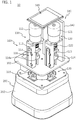
- FIG. 1 is a perspective view showing a head of an ultrasonic treatment apparatus according to the present invention
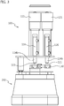
- FIG. 2 is a side view showing a side of the head shown in FIG. 1
- FIG. 3 is a side view showing another side of the head shown in FIG. 1 .
- An ultrasonic treatment head 10 includes a head body 100 having a shape that is easily held by a user's hand and put on the skin of a patient for treatment and a cartridge 200 detachably coupled to the head body 100 and performing in-plane scanning on a treatment area by generating ultrasonic waves in accordance with operation of the head body 100.
- the ultrasonic treatment head 10 When the ultrasonic treatment head 10 according to the present invention is a portable independent part, it can be independently operated by controller in the head body when power is supplied, but when a separate controller is provided, the head may be connected with an external controller through a cable or wirelessly.
- the ultrasonic treatment head 10 is composed of the head body 100 and the cartridge 200 detachably coupled to the head body 100.
- the head body 100 includes a body housing (not shown) for supporting and protecting internal components and providing an interface for a user, a first actuator 110 generating translation (reciprocation) on a first axis, a second actuator 120 generating translation (reciprocation) on a second axis, and a stage 130 pivoted about a fixed axis by the first actuator 110 and the second actuator 120.
- the cartridge 200 which will be described in detail below, includes a cartridge housing 202 for keeping a transducer and liquid therein, a flat window 228 (see FIG. 5 ) disposed on the cartridge housing to transmit ultrasonic waves to a treatment area, a body coupler for coupling to the head body, an ultrasonic transducer 226 generating ultrasonic waves in response to an operation signal input through the body coupler, and a fitting assembly moving the ultrasonic transducer 226 on the flat window 228 for in-plane scanning by a pivot motion, which is transmitted through the body coupler, of the stage.
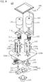
- FIG. 4 is an exploded perspective view of a head body having an operation assembly in the head according to the present invention.
- the first actuator 110 generating translation (reciprocation) on the first axis includes: a BLDC motor (111); a lead screw 113, a coupler 112 for coupling a rotary shaft of the BLDC motor 11 to the lead screw 113; a support frame 117 for supporting the lead screw 113; a slider 114 reciprocating with rotation of the lead screw; a position resistor 116 for detecting the position of the slider 114, and a ball joint 115 disposed at a free end of the slider 114.
- the second actuator 120 generating translation (reciprocation) on the second axis includes: a BLDC motor 121; a lead screw 123; a coupler 122 for coupling to a rotary shaft of the BLDC motor to the lead screw 123; a support frame 127 for supporting the lead screw; a slider 124 reciprocating with rotation of the lead screw; a position resistor 126 for detecting the position of the slider; and a ball joint 125 disposed at a free end of the slider.
- the stage 130 has three holes 131, 132, and 133 for coupling a fixed ball joint 134 fastened to a base plate 102, a first axis ball joint 115, and a second axis ball joint 125 on the top and has a coupling member 135 for coupling to the cartridge 200 on the bottom.
- the stage 130 is firmly coupled to the cartridge by a magnet so that when the stage 130 is operated, the fitting assembly of the cartridge can move a transducer.
- the head body 100 includes a display or a touch screen 141 mounted on the body housing to provide an interface for a user and a control board 142 controlling operation of the first actuator 110 and the second actuator and operating the transducer by executing software programmed in accordance with a predetermined scan algorism.
- the position resistors 116 and 126 of the actuators are connected to the control board 142, and change the rotational directions of the actuators when the sliders 114 and 124 reach an upper limit or a lower limit.
- a sensor for checking whether the cartridge 200 has been normally coupled may be additionally mounted on the head body 100.
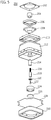
- FIG. 5 is an exploded perspective view of a cartridge that is mounted on the head body according to the present invention.
- the cartridge 200 includes a cartridge PCB 202, a cartridge coupler 204, a bellows support spring 206, a bellows 208, a top cover 210, a cartridge housing 212, a first support 214, a compression spring 216, a second support 218, a disc 220, a ball joint 222, a transducer housing 224, a transducer 226, a flat window 228, and a bottom cover 230.
- the cartridge PCB 202 and the cartridge coupler 204 form a body coupling unit for coupling to the head body 100 and are fastened to a contact connector and a coupling portion of the head body 110 to connect a pivot motion of the stage 130 and electrical signals from the control board 142.
- the bellows 208 is coupled to the cartridge housing 212 through the bellows housing 206 to allow movement of the transducer therein and prevents liquid therein from leaking and the flat window 228 is mounted on the cartridge housing 212 to transmit ultrasonic waves to a treatment area.
- the top cover 210 and the bottom cover 230 are fastened to the cartridge housing 212 and seal the cartridge in cooperation with the bellows 208 and the window 228 to prevent leakage of liquid that is a medium for transmitting ultrasonic waves.
- the fitting assembly is composed of the first support 214 having a hole therein and coupled to the body coupler, the compression spring 226 inserted in the hole of the first support 214, a second support 218 inserted in the hole of the first support 214 to compress the compression spring 216, the ball joint 222 coupled to the second support, and the transducer housing 224 combined with the ball joint 222.
- the fitting assembly moves the ultrasonic transducer 226 for in-plane scanning along the flat window 228 by a pivot motion, which is transmitted through the body coupler, of the stage due to ball joint-coupling of the transducer housing.
- the ultrasonic transducer 226 is fastened to the transducer housing 224 and generates an ultrasonic wave when an operation signal is input through the body coupler.
- the depth of a focus area depends on the treatment purpose in ultrasonic treatment, so a cartridge 200 suitable for the treatment purpose is selected and mounted on the head body 100. Further, it is possible to select an appropriate scan pattern or operation time, depending on the treatment portion or purpose.
- the controller 140 starts the first actuator 110 and the second actuator 120 and operates the transducer 226 in accordance with a preprogrammed scan pattern to generate ultrasonic waves or high intensity focused ultrasound.
- the stage 130 pivots in various directions due to combination of a pivot motion by the first axis ball joint and a pivot motion by the second axis ball joint.
- the controller 140 When it is detected through the position resistor 116 that the slider 114 of the first actuator has reached a lower limit, the controller 140 changes the rotational direction of the first actuator in the opposite direction, and accordingly, the slider 114 is moved upward. When it is detected through the position resistor 116 that the slider 114 of the first actuator has reached an upper limit in the same way, the controller 140 changes again the rotational direction of the first actuator 110 back into the opposite direction for downward movement, so the slider 114 pushes or pulls the stage 130 by reciprocating between the upper limit and the lower limit.
- the pivot motion of the stage 130 is transmitted to the fitting assembly of the cartridge 200 and the fitting assembly moves the transducer 226 at the end on the flat window 228 by the pivot motion.
- the fitting assembly is changed in the entire axial length by the compression spring 216, so it allows for in-plane scanning by converting the pivot motion into in-plane movement. That is, the fitting assembly is contracted and the spring 216 is compressed much at the center of the flat window 228, and as the fitting assembly moves outward, the compression spring 216 is decompressed and the length of the fitting assembly is stretched, so in-plane scanning is performed in the flat window area. Accordingly, the ultrasonic focus depth of the transducer is made uniform even at the center and the edge in a plane.
Landscapes
- Health & Medical Sciences (AREA)
- Life Sciences & Earth Sciences (AREA)
- Public Health (AREA)
- Veterinary Medicine (AREA)
- Radiology & Medical Imaging (AREA)
- Biomedical Technology (AREA)
- Animal Behavior & Ethology (AREA)
- General Health & Medical Sciences (AREA)
- Engineering & Computer Science (AREA)
- Nuclear Medicine, Radiotherapy & Molecular Imaging (AREA)
- Physics & Mathematics (AREA)
- Biophysics (AREA)
- Pathology (AREA)
- Heart & Thoracic Surgery (AREA)
- Medical Informatics (AREA)
- Molecular Biology (AREA)
- Surgery (AREA)
- Surgical Instruments (AREA)
Applications Claiming Priority (2)
| Application Number | Priority Date | Filing Date | Title |
|---|---|---|---|
| KR20140145219 | 2014-10-24 | ||
| PCT/KR2014/010701 WO2016064016A1 (fr) | 2014-10-24 | 2014-11-07 | Cartouche à ultrasons et tête de traitement par ultrasons l'utilisant |
Publications (3)
| Publication Number | Publication Date |
|---|---|
| EP3210649A1 true EP3210649A1 (fr) | 2017-08-30 |
| EP3210649A4 EP3210649A4 (fr) | 2018-07-04 |
| EP3210649B1 EP3210649B1 (fr) | 2019-09-04 |
Family
ID=55761045
Family Applications (1)
| Application Number | Title | Priority Date | Filing Date |
|---|---|---|---|
| EP14904353.1A Active EP3210649B1 (fr) | 2014-10-24 | 2014-11-07 | Cartouche à ultrasons et tête de traitement par ultrasons l'utilisant |
Country Status (6)
| Country | Link |
|---|---|
| US (1) | US20170303888A1 (fr) |
| EP (1) | EP3210649B1 (fr) |
| KR (2) | KR101635636B1 (fr) |
| CN (1) | CN107073290B (fr) |
| AU (1) | AU2014409333B2 (fr) |
| WO (1) | WO2016064016A1 (fr) |
Families Citing this family (13)
| Publication number | Priority date | Publication date | Assignee | Title |
|---|---|---|---|---|
| KR101775694B1 (ko) * | 2016-05-04 | 2017-09-06 | (주)클래시스 | 초음파 트랜스듀서 운동장치 및 이를 이용한 초음파 치료용 헤드 |
| WO2017176009A1 (fr) * | 2016-04-05 | 2017-10-12 | (주)클래시스 | Appareil d'exercice à transducteur ultrasonore et tête thérapeutique ultrasonore l'utilisant |
| KR101782523B1 (ko) * | 2016-05-04 | 2017-10-23 | (주)클래시스 | 초음파 트랜스듀서 운동장치 및 이를 이용한 초음파 치료용 헤드 |
| KR101677903B1 (ko) * | 2016-05-16 | 2016-11-21 | 정성재 | 초음파 카트리지와 이를 이용한 초음파 치료용 헤드 |
| KR101688424B1 (ko) * | 2016-05-30 | 2017-01-02 | 정성재 | 초음파 카트리지와 이를 이용한 초음파 치료용 헤드 |
| KR101824462B1 (ko) * | 2016-12-29 | 2018-02-01 | (주)클래시스 | 초음파 카트리지와 이를 이용한 초음파 치료용 헤드 |
| CN108324324A (zh) * | 2018-03-12 | 2018-07-27 | 西安交通大学 | 一种超声低频经颅容积超分辨率三维造影成像方法及系统 |
| CN109821161A (zh) * | 2019-03-22 | 2019-05-31 | 常州立新医疗美容诊所有限公司 | 一种医疗整形溶脂设备 |
| CN110664437B (zh) * | 2019-10-22 | 2024-09-13 | 深圳瀚维智能医疗科技有限公司 | 自动超声乳房扫描设备 |
| KR102135733B1 (ko) * | 2019-12-16 | 2020-07-20 | (주)클래시스 | 치료용 초음파 발생장치 및 이를 포함하는 초음파 치료용 핸드피스 |
| KR102521030B1 (ko) * | 2020-09-09 | 2023-04-12 | 주식회사 제이시스메디칼 | 초음파 의료용 카트리지 및 이를 포함하는 초음파 의료 장치 |
| CN115154253B (zh) * | 2022-09-08 | 2022-11-08 | 苏州好博医疗器械股份有限公司 | 一种具有自主移动功能的超声波治疗头 |
| WO2025089446A1 (fr) | 2023-10-23 | 2025-05-01 | (주)아이엠지티 | Tête de thérapie par ultrasons |
Family Cites Families (14)
| Publication number | Priority date | Publication date | Assignee | Title |
|---|---|---|---|---|
| US5402789A (en) * | 1992-11-23 | 1995-04-04 | Capistrano Labs, Inc. | Ultrasonic peripheral vascular probe assembly |
| JP2007516810A (ja) * | 2003-12-30 | 2007-06-28 | ライポソニックス, インコーポレイテッド | 動作制御を有する超音波治療ヘッド |
| CN1754586B (zh) * | 2004-09-30 | 2010-09-01 | 重庆海扶(Hifu)技术有限公司 | 超声治疗头及具有该治疗头的超声治疗仪 |
| MX2010008314A (es) * | 2008-02-01 | 2010-10-20 | Medicis Technologies Corp | Cabezal terapeutico para usarse con un sistema de ultrasonido. |
| JP5155693B2 (ja) * | 2008-02-26 | 2013-03-06 | 東芝プラントシステム株式会社 | 超音波検査装置 |
| WO2010040140A2 (fr) | 2008-10-03 | 2010-04-08 | Mirabilis Mdedica, Inc. | Méthode et appareil permettant de traiter des tissus avec des ufhi |
| KR101117275B1 (ko) * | 2009-07-22 | 2012-03-20 | 김완철 | 초음파를 이용한 지방분해 장치 |
| US8425435B2 (en) * | 2009-09-29 | 2013-04-23 | Liposonix, Inc. | Transducer cartridge for an ultrasound therapy head |
| US9573000B2 (en) * | 2010-08-18 | 2017-02-21 | Mirabilis Medica Inc. | HIFU applicator |
| KR101191347B1 (ko) * | 2010-10-20 | 2012-10-15 | (주)클래시스 | 고강도집속초음파장치용 3차원이송식 핸드피스 |
| KR101177691B1 (ko) * | 2012-07-09 | 2012-08-29 | (주)클래시스 | 고강도 집속형 초음파를 이용한 비침습성 피하지방 감소 장치의 3축 제어 헤드 |
| US9289188B2 (en) * | 2012-12-03 | 2016-03-22 | Liposonix, Inc. | Ultrasonic transducer |
| KR101307551B1 (ko) * | 2013-03-26 | 2013-09-12 | (주)클래시스 | 초음파 장치의 핸드피스 |
| CN104107510B (zh) * | 2014-07-31 | 2017-07-14 | 重庆海扶医疗科技股份有限公司 | 高强度聚焦超声治疗系统的运动扫描装置 |
-
2014
- 2014-11-07 US US15/521,327 patent/US20170303888A1/en not_active Abandoned
- 2014-11-07 WO PCT/KR2014/010701 patent/WO2016064016A1/fr not_active Ceased
- 2014-11-07 AU AU2014409333A patent/AU2014409333B2/en active Active
- 2014-11-07 CN CN201480082888.6A patent/CN107073290B/zh active Active
- 2014-11-07 EP EP14904353.1A patent/EP3210649B1/fr active Active
-
2015
- 2015-09-16 KR KR1020150131026A patent/KR101635636B1/ko active Active
-
2016
- 2016-06-20 KR KR1020160076614A patent/KR101824465B1/ko active Active
Also Published As
| Publication number | Publication date |
|---|---|
| KR20160048641A (ko) | 2016-05-04 |
| KR101824465B1 (ko) | 2018-03-14 |
| CN107073290B (zh) | 2019-04-02 |
| AU2014409333B2 (en) | 2017-11-09 |
| EP3210649B1 (fr) | 2019-09-04 |
| EP3210649A4 (fr) | 2018-07-04 |
| CN107073290A (zh) | 2017-08-18 |
| US20170303888A1 (en) | 2017-10-26 |
| KR101635636B1 (ko) | 2016-07-01 |
| KR20160075472A (ko) | 2016-06-29 |
| WO2016064016A1 (fr) | 2016-04-28 |
| AU2014409333A1 (en) | 2017-06-15 |
Similar Documents
| Publication | Publication Date | Title |
|---|---|---|
| EP3210649B1 (fr) | Cartouche à ultrasons et tête de traitement par ultrasons l'utilisant | |
| AU2024213113B2 (en) | Systems and methods for cosmetic ultrasound treatment of skin | |
| KR101177691B1 (ko) | 고강도 집속형 초음파를 이용한 비침습성 피하지방 감소 장치의 3축 제어 헤드 | |
| EP4140541B1 (fr) | Générateur d'ultrasons à profondeur de focalisation ultrasonore réglable pour traitement de l'obésité | |
| CN105050660B (zh) | 超声波装置的手持件 | |
| KR101677903B1 (ko) | 초음파 카트리지와 이를 이용한 초음파 치료용 헤드 | |
| KR101688424B1 (ko) | 초음파 카트리지와 이를 이용한 초음파 치료용 헤드 | |
| KR101824464B1 (ko) | 초음파 카트리지 | |
| US20110144544A1 (en) | Ultrasound transducer assembly and methods of using | |
| KR101824462B1 (ko) | 초음파 카트리지와 이를 이용한 초음파 치료용 헤드 | |
| KR102083971B1 (ko) | 초음파 카트리지와 이를 이용한 초음파 치료용 헤드 | |
| JP2009502267A (ja) | Mriでガイドされる強力集束超音波治療システム | |
| IL267748A (en) | Methods and systems for continuous ultrasonic monitoring without hand contact | |
| KR20160059972A (ko) | 초음파를 이용한 의료장치 및 트랜스듀서의 이동 제어 방법 | |
| KR101782523B1 (ko) | 초음파 트랜스듀서 운동장치 및 이를 이용한 초음파 치료용 헤드 | |
| KR101643885B1 (ko) | 초음파 카트리지 | |
| KR101775694B1 (ko) | 초음파 트랜스듀서 운동장치 및 이를 이용한 초음파 치료용 헤드 | |
| KR101902895B1 (ko) | 초음파 트랜스듀서 작동용 피봇 운동 구조체 | |
| KR101874532B1 (ko) | 초음파 치료용 헤드 | |
| EP2943111B1 (fr) | Sonde ultrasonore laparoscopique pour imagerie élastographique comprenant un mécanisme à oscillation automatisée |
Legal Events
| Date | Code | Title | Description |
|---|---|---|---|
| STAA | Information on the status of an ep patent application or granted ep patent |
Free format text: STATUS: THE INTERNATIONAL PUBLICATION HAS BEEN MADE |
|
| PUAI | Public reference made under article 153(3) epc to a published international application that has entered the european phase |
Free format text: ORIGINAL CODE: 0009012 |
|
| STAA | Information on the status of an ep patent application or granted ep patent |
Free format text: STATUS: REQUEST FOR EXAMINATION WAS MADE |
|
| 17P | Request for examination filed |
Effective date: 20170524 |
|
| AK | Designated contracting states |
Kind code of ref document: A1 Designated state(s): AL AT BE BG CH CY CZ DE DK EE ES FI FR GB GR HR HU IE IS IT LI LT LU LV MC MK MT NL NO PL PT RO RS SE SI SK SM TR |
|
| AX | Request for extension of the european patent |
Extension state: BA ME |
|
| DAX | Request for extension of the european patent (deleted) | ||
| RIC1 | Information provided on ipc code assigned before grant |
Ipc: A61N 7/02 20060101ALI20180523BHEP Ipc: A61N 7/00 20060101AFI20180523BHEP |
|
| A4 | Supplementary search report drawn up and despatched |
Effective date: 20180601 |
|
| GRAP | Despatch of communication of intention to grant a patent |
Free format text: ORIGINAL CODE: EPIDOSNIGR1 |
|
| STAA | Information on the status of an ep patent application or granted ep patent |
Free format text: STATUS: GRANT OF PATENT IS INTENDED |
|
| INTG | Intention to grant announced |
Effective date: 20190405 |
|
| GRAS | Grant fee paid |
Free format text: ORIGINAL CODE: EPIDOSNIGR3 |
|
| GRAA | (expected) grant |
Free format text: ORIGINAL CODE: 0009210 |
|
| STAA | Information on the status of an ep patent application or granted ep patent |
Free format text: STATUS: THE PATENT HAS BEEN GRANTED |
|
| AK | Designated contracting states |
Kind code of ref document: B1 Designated state(s): AL AT BE BG CH CY CZ DE DK EE ES FI FR GB GR HR HU IE IS IT LI LT LU LV MC MK MT NL NO PL PT RO RS SE SI SK SM TR |
|
| REG | Reference to a national code |
Ref country code: GB Ref legal event code: FG4D |
|
| REG | Reference to a national code |
Ref country code: CH Ref legal event code: EP |
|
| REG | Reference to a national code |
Ref country code: AT Ref legal event code: REF Ref document number: 1174524 Country of ref document: AT Kind code of ref document: T Effective date: 20190915 |
|
| REG | Reference to a national code |
Ref country code: DE Ref legal event code: R096 Ref document number: 602014053255 Country of ref document: DE |
|
| REG | Reference to a national code |
Ref country code: IE Ref legal event code: FG4D |
|
| REG | Reference to a national code |
Ref country code: NL Ref legal event code: MP Effective date: 20190904 |
|
| REG | Reference to a national code |
Ref country code: LT Ref legal event code: MG4D |
|
| PG25 | Lapsed in a contracting state [announced via postgrant information from national office to epo] |
Ref country code: NO Free format text: LAPSE BECAUSE OF FAILURE TO SUBMIT A TRANSLATION OF THE DESCRIPTION OR TO PAY THE FEE WITHIN THE PRESCRIBED TIME-LIMIT Effective date: 20191204 Ref country code: HR Free format text: LAPSE BECAUSE OF FAILURE TO SUBMIT A TRANSLATION OF THE DESCRIPTION OR TO PAY THE FEE WITHIN THE PRESCRIBED TIME-LIMIT Effective date: 20190904 Ref country code: SE Free format text: LAPSE BECAUSE OF FAILURE TO SUBMIT A TRANSLATION OF THE DESCRIPTION OR TO PAY THE FEE WITHIN THE PRESCRIBED TIME-LIMIT Effective date: 20190904 Ref country code: FI Free format text: LAPSE BECAUSE OF FAILURE TO SUBMIT A TRANSLATION OF THE DESCRIPTION OR TO PAY THE FEE WITHIN THE PRESCRIBED TIME-LIMIT Effective date: 20190904 Ref country code: LT Free format text: LAPSE BECAUSE OF FAILURE TO SUBMIT A TRANSLATION OF THE DESCRIPTION OR TO PAY THE FEE WITHIN THE PRESCRIBED TIME-LIMIT Effective date: 20190904 Ref country code: BG Free format text: LAPSE BECAUSE OF FAILURE TO SUBMIT A TRANSLATION OF THE DESCRIPTION OR TO PAY THE FEE WITHIN THE PRESCRIBED TIME-LIMIT Effective date: 20191204 |
|
| PG25 | Lapsed in a contracting state [announced via postgrant information from national office to epo] |
Ref country code: AL Free format text: LAPSE BECAUSE OF FAILURE TO SUBMIT A TRANSLATION OF THE DESCRIPTION OR TO PAY THE FEE WITHIN THE PRESCRIBED TIME-LIMIT Effective date: 20190904 Ref country code: ES Free format text: LAPSE BECAUSE OF FAILURE TO SUBMIT A TRANSLATION OF THE DESCRIPTION OR TO PAY THE FEE WITHIN THE PRESCRIBED TIME-LIMIT Effective date: 20190904 Ref country code: GR Free format text: LAPSE BECAUSE OF FAILURE TO SUBMIT A TRANSLATION OF THE DESCRIPTION OR TO PAY THE FEE WITHIN THE PRESCRIBED TIME-LIMIT Effective date: 20191205 Ref country code: LV Free format text: LAPSE BECAUSE OF FAILURE TO SUBMIT A TRANSLATION OF THE DESCRIPTION OR TO PAY THE FEE WITHIN THE PRESCRIBED TIME-LIMIT Effective date: 20190904 Ref country code: RS Free format text: LAPSE BECAUSE OF FAILURE TO SUBMIT A TRANSLATION OF THE DESCRIPTION OR TO PAY THE FEE WITHIN THE PRESCRIBED TIME-LIMIT Effective date: 20190904 |
|
| REG | Reference to a national code |
Ref country code: AT Ref legal event code: MK05 Ref document number: 1174524 Country of ref document: AT Kind code of ref document: T Effective date: 20190904 |
|
| PG25 | Lapsed in a contracting state [announced via postgrant information from national office to epo] |
Ref country code: PT Free format text: LAPSE BECAUSE OF FAILURE TO SUBMIT A TRANSLATION OF THE DESCRIPTION OR TO PAY THE FEE WITHIN THE PRESCRIBED TIME-LIMIT Effective date: 20200106 Ref country code: RO Free format text: LAPSE BECAUSE OF FAILURE TO SUBMIT A TRANSLATION OF THE DESCRIPTION OR TO PAY THE FEE WITHIN THE PRESCRIBED TIME-LIMIT Effective date: 20190904 Ref country code: NL Free format text: LAPSE BECAUSE OF FAILURE TO SUBMIT A TRANSLATION OF THE DESCRIPTION OR TO PAY THE FEE WITHIN THE PRESCRIBED TIME-LIMIT Effective date: 20190904 Ref country code: EE Free format text: LAPSE BECAUSE OF FAILURE TO SUBMIT A TRANSLATION OF THE DESCRIPTION OR TO PAY THE FEE WITHIN THE PRESCRIBED TIME-LIMIT Effective date: 20190904 Ref country code: PL Free format text: LAPSE BECAUSE OF FAILURE TO SUBMIT A TRANSLATION OF THE DESCRIPTION OR TO PAY THE FEE WITHIN THE PRESCRIBED TIME-LIMIT Effective date: 20190904 Ref country code: AT Free format text: LAPSE BECAUSE OF FAILURE TO SUBMIT A TRANSLATION OF THE DESCRIPTION OR TO PAY THE FEE WITHIN THE PRESCRIBED TIME-LIMIT Effective date: 20190904 |
|
| PG25 | Lapsed in a contracting state [announced via postgrant information from national office to epo] |
Ref country code: IS Free format text: LAPSE BECAUSE OF FAILURE TO SUBMIT A TRANSLATION OF THE DESCRIPTION OR TO PAY THE FEE WITHIN THE PRESCRIBED TIME-LIMIT Effective date: 20200224 Ref country code: SM Free format text: LAPSE BECAUSE OF FAILURE TO SUBMIT A TRANSLATION OF THE DESCRIPTION OR TO PAY THE FEE WITHIN THE PRESCRIBED TIME-LIMIT Effective date: 20190904 Ref country code: SK Free format text: LAPSE BECAUSE OF FAILURE TO SUBMIT A TRANSLATION OF THE DESCRIPTION OR TO PAY THE FEE WITHIN THE PRESCRIBED TIME-LIMIT Effective date: 20190904 Ref country code: CZ Free format text: LAPSE BECAUSE OF FAILURE TO SUBMIT A TRANSLATION OF THE DESCRIPTION OR TO PAY THE FEE WITHIN THE PRESCRIBED TIME-LIMIT Effective date: 20190904 |
|
| REG | Reference to a national code |
Ref country code: DE Ref legal event code: R097 Ref document number: 602014053255 Country of ref document: DE |
|
| PLBE | No opposition filed within time limit |
Free format text: ORIGINAL CODE: 0009261 |
|
| STAA | Information on the status of an ep patent application or granted ep patent |
Free format text: STATUS: NO OPPOSITION FILED WITHIN TIME LIMIT |
|
| PG2D | Information on lapse in contracting state deleted |
Ref country code: IS |
|
| PG25 | Lapsed in a contracting state [announced via postgrant information from national office to epo] |
Ref country code: DK Free format text: LAPSE BECAUSE OF FAILURE TO SUBMIT A TRANSLATION OF THE DESCRIPTION OR TO PAY THE FEE WITHIN THE PRESCRIBED TIME-LIMIT Effective date: 20190904 Ref country code: LU Free format text: LAPSE BECAUSE OF NON-PAYMENT OF DUE FEES Effective date: 20191107 Ref country code: MC Free format text: LAPSE BECAUSE OF FAILURE TO SUBMIT A TRANSLATION OF THE DESCRIPTION OR TO PAY THE FEE WITHIN THE PRESCRIBED TIME-LIMIT Effective date: 20190904 Ref country code: IS Free format text: LAPSE BECAUSE OF FAILURE TO SUBMIT A TRANSLATION OF THE DESCRIPTION OR TO PAY THE FEE WITHIN THE PRESCRIBED TIME-LIMIT Effective date: 20200105 |
|
| 26N | No opposition filed |
Effective date: 20200605 |
|
| REG | Reference to a national code |
Ref country code: BE Ref legal event code: MM Effective date: 20191130 |
|
| PG25 | Lapsed in a contracting state [announced via postgrant information from national office to epo] |
Ref country code: SI Free format text: LAPSE BECAUSE OF FAILURE TO SUBMIT A TRANSLATION OF THE DESCRIPTION OR TO PAY THE FEE WITHIN THE PRESCRIBED TIME-LIMIT Effective date: 20190904 |
|
| GBPC | Gb: european patent ceased through non-payment of renewal fee |
Effective date: 20191204 |
|
| PG25 | Lapsed in a contracting state [announced via postgrant information from national office to epo] |
Ref country code: GB Free format text: LAPSE BECAUSE OF NON-PAYMENT OF DUE FEES Effective date: 20191204 Ref country code: FR Free format text: LAPSE BECAUSE OF NON-PAYMENT OF DUE FEES Effective date: 20191130 Ref country code: IE Free format text: LAPSE BECAUSE OF NON-PAYMENT OF DUE FEES Effective date: 20191107 |
|
| PG25 | Lapsed in a contracting state [announced via postgrant information from national office to epo] |
Ref country code: BE Free format text: LAPSE BECAUSE OF NON-PAYMENT OF DUE FEES Effective date: 20191130 |
|
| PG25 | Lapsed in a contracting state [announced via postgrant information from national office to epo] |
Ref country code: CY Free format text: LAPSE BECAUSE OF FAILURE TO SUBMIT A TRANSLATION OF THE DESCRIPTION OR TO PAY THE FEE WITHIN THE PRESCRIBED TIME-LIMIT Effective date: 20190904 |
|
| PG25 | Lapsed in a contracting state [announced via postgrant information from national office to epo] |
Ref country code: HU Free format text: LAPSE BECAUSE OF FAILURE TO SUBMIT A TRANSLATION OF THE DESCRIPTION OR TO PAY THE FEE WITHIN THE PRESCRIBED TIME-LIMIT; INVALID AB INITIO Effective date: 20141107 Ref country code: MT Free format text: LAPSE BECAUSE OF FAILURE TO SUBMIT A TRANSLATION OF THE DESCRIPTION OR TO PAY THE FEE WITHIN THE PRESCRIBED TIME-LIMIT Effective date: 20190904 |
|
| PG25 | Lapsed in a contracting state [announced via postgrant information from national office to epo] |
Ref country code: TR Free format text: LAPSE BECAUSE OF FAILURE TO SUBMIT A TRANSLATION OF THE DESCRIPTION OR TO PAY THE FEE WITHIN THE PRESCRIBED TIME-LIMIT Effective date: 20190904 |
|
| PG25 | Lapsed in a contracting state [announced via postgrant information from national office to epo] |
Ref country code: MK Free format text: LAPSE BECAUSE OF FAILURE TO SUBMIT A TRANSLATION OF THE DESCRIPTION OR TO PAY THE FEE WITHIN THE PRESCRIBED TIME-LIMIT Effective date: 20190904 |
|
| REG | Reference to a national code |
Ref country code: CH Ref legal event code: U11 Free format text: ST27 STATUS EVENT CODE: U-0-0-U10-U11 (AS PROVIDED BY THE NATIONAL OFFICE) Effective date: 20251201 |
|
| PGFP | Annual fee paid to national office [announced via postgrant information from national office to epo] |
Ref country code: DE Payment date: 20251117 Year of fee payment: 12 |
|
| PGFP | Annual fee paid to national office [announced via postgrant information from national office to epo] |
Ref country code: IT Payment date: 20251110 Year of fee payment: 12 |
|
| PGFP | Annual fee paid to national office [announced via postgrant information from national office to epo] |
Ref country code: CH Payment date: 20251201 Year of fee payment: 12 |
|
| REG | Reference to a national code |
Ref country code: DE Ref legal event code: R082 Ref document number: 602014053255 Country of ref document: DE Representative=s name: VUILLERMOZ, BRUNO, FR |