EP3210927B1 - Aufzugsvorrichtung - Google Patents
Aufzugsvorrichtung Download PDFInfo
- Publication number
- EP3210927B1 EP3210927B1 EP14904518.9A EP14904518A EP3210927B1 EP 3210927 B1 EP3210927 B1 EP 3210927B1 EP 14904518 A EP14904518 A EP 14904518A EP 3210927 B1 EP3210927 B1 EP 3210927B1
- Authority
- EP
- European Patent Office
- Prior art keywords
- opening
- closing door
- buffer material
- receiving member
- material receiving
- Prior art date
- Legal status (The legal status is an assumption and is not a legal conclusion. Google has not performed a legal analysis and makes no representation as to the accuracy of the status listed.)
- Active
Links
Images


Classifications
-
- B—PERFORMING OPERATIONS; TRANSPORTING
- B66—HOISTING; LIFTING; HAULING
- B66B—ELEVATORS; ESCALATORS OR MOVING WALKWAYS
- B66B13/00—Doors, gates, or other apparatus controlling access to, or exit from, cages or lift well landings
- B66B13/30—Constructional features of doors or gates
-
- B—PERFORMING OPERATIONS; TRANSPORTING
- B66—HOISTING; LIFTING; HAULING
- B66B—ELEVATORS; ESCALATORS OR MOVING WALKWAYS
- B66B13/00—Doors, gates, or other apparatus controlling access to, or exit from, cages or lift well landings
- B66B13/02—Door or gate operation
- B66B13/06—Door or gate operation of sliding doors
- B66B13/08—Door or gate operation of sliding doors guided for horizontal movement
-
- E—FIXED CONSTRUCTIONS
- E05—LOCKS; KEYS; WINDOW OR DOOR FITTINGS; SAFES
- E05Y—INDEXING SCHEME ASSOCIATED WITH SUBCLASSES E05D AND E05F, RELATING TO CONSTRUCTION ELEMENTS, ELECTRIC CONTROL, POWER SUPPLY, POWER SIGNAL OR TRANSMISSION, USER INTERFACES, MOUNTING OR COUPLING, DETAILS, ACCESSORIES, AUXILIARY OPERATIONS NOT OTHERWISE PROVIDED FOR, APPLICATION THEREOF
- E05Y2900/00—Application of doors, windows, wings or fittings thereof
- E05Y2900/10—Application of doors, windows, wings or fittings thereof for buildings or parts thereof
- E05Y2900/104—Application of doors, windows, wings or fittings thereof for buildings or parts thereof for elevators
Definitions
- the present invention relates: to an elevator apparatus to carry a passenger or a package; and in particular to an elevator apparatus having an opening and closing door for platform installed at an elevator platform.
- An opening and closing door for platform (hereunder described merely as an opening and closing door) through which a passenger comes in and out is installed at a gateway of an elevator apparatus at an elevator platform.
- the opening and closing door is configured by: installing two doors so as to overlap; and closing a gateway by shifting one door until it touches an end surface of the gateway on the closing side and shifting the other door up to a halfway position when the opening and closing door is closed. Then when the opening and closing door is opened, the gateway is fully opened by: shifting the one door and the other door up to the end surface of the gateway on the opening side; and overlapping the one door and the other door to each other in the state.
- Such an opening and closing door is called an opening and closing door of a two-leaved single-swing type.
- opening and closing doors are configured so as to fully close in order to prevent flames and hot air from intruding into a hoistway when a fire breaks out in a building but flames and hot air may sometimes intrude into a hoistway through gaps between a building and opening and closing doors. Then the intruding flames and hot air may sometimes reach hanger rails and hanger rollers installed in order to suspend opening and closing doors and shift the opening and closing doors smoothly.
- the hanger rails extend in the directions in which the opening and closing doors shift and are fixed to the upper part of the hoistway above the platform gateway in the building with bolts or the like. Then the hanger rollers installed in door hangers fixed to the opening and closing doors roll over rails formed at the upper parts of the hanger rails and shift the opening and closing doors smoothly. Then a buffer material comprising a synthetic resin such as an urethane resin or a nylon resin is installed over the rolling surfaces of the hanger rollers and the configuration is arranged so as to: alleviate impact between the hanger rollers and the rail surfaces of the hanger rails; and inhibit shifting sounds and vibrations accompanying the shift of the opening and closing doors.
- a buffer material comprising a synthetic resin such as an urethane resin or a nylon resin
- the buffer material may sometimes melt by flames or hot air, however, because it comprises a synthetic resin and the melting buffer material drops directly into a hoistway. On this occasion, if a passenger cage is located on the lower side, the melting buffer material may drop onto the passenger cage and get fire undesirably. Otherwise, even when a passenger cage does not exist, a fire may break out in a hoistway sometimes. For the reason, a measure of inhibiting a melting buffer material from dropping into a hoistway is desired.
- Japanese Patent Application Laid-Open No. 2002-220181 proposes to install a gutter-shaped member to receive a melting buffer material and drain the melting buffer material toward the platform side under a hanger rail so that the melting buffer material may not drop into a hoistway.
- an opening and closing door having a hanger rail to suspend the opening and closing door, a pocket to fix the hanger rail, a door hanger to be fixed to the upper part of the opening and closing door and suspend the opening and closing door to the hanger rail, a hanger roller to be rotatably installed in the door hanger and roll over the hanger rail, and a buffer material installed over the rolling surface of the hanger roller, in order to prevent the melting buffer material of the hanger roller from dropping onto the side of a hoistway, a gutter-shaped member to receive and drain the melting buffer material toward the center of the opening and closing door is installed under the hanger roller.
- PTL 2 describes an elevator layer door, specially an elevator fireproof heat insulation layer door.
- An opening and closing door proposed in PTL 1 is configured so that a melting buffer material of a hanger roller may be received by a gutter-shaped member, accumulated in the center of the opening and closing door, and drained toward the side of a platform and hence the melting buffer material may sometimes drop over a gateway upper frame constituting a platform gateway in a building. Since the gateway upper frame is located above the platform gateway, the temperature tends to rise by flames and hot air and sometimes rises to a high temperature exceeding the ignition point of a buffer material.
- An object of the present invention is to provide an elevator apparatus having a novel opening and closing door excellent in fire-resistance performance.
- a feature of the present invention is to inhibit a melting buffer material from dropping over a gateway upper frame of a high temperature by: arranging a buffer material receiving member that extends in the directions of shifting a hanger roller and receives the melting buffer material between the upper part of the gateway upper frame and the hanger roller; and receiving the melting buffer material with the buffer material receiving member.
- the present invention makes it possible to: receive a melting buffer material with a buffer material receiving member; and inhibit the melting buffer material from dropping over a gateway upper frame of a high temperature. As a result, the danger of igniting a melting buffer material in a hoistway reduces and an opening and closing door excellent in fire-resistance performance can be provided.
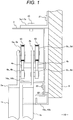
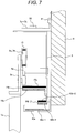
- Fig. 1 is a view of the upper part of a two-leaved single-swing opening and closing door according to a first embodiment of the present invention viewed from a side
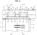
- Fig. 2 is a view of the opening and closing door shown in Fig. 1 viewed from a hoistway side
- Fig. 3 is a sectional view taken on line A-A in Fig. 2
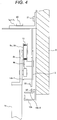
- Fig. 4 is a sectional view taken on line B-B in Fig. 2 .
- a first opening and closing door 1a and a second opening and closing door 1b installed at a platform gateway shift to fully closed positions respectively and close the platform gateway in a closing state; and shift to fully open positions respectively and overlap each other in an opening state.
- the first opening and closing door 1a and the second opening and closing door 1b are: opened toward the right side shown with the arrow O in Fig. 2 ; and closed toward the left side shown with the arrow C in Fig. 2 . Consequently, the second opening and closing door 1b is located on the closer side than the first opening and closing door 1a (on the platform side).
- door hangers 2a and 2b are fixed to the top ends of the first opening and closing door 1a and the second opening and closing door 1b by a method of bolting or welding.
- the door hangers 2a and 2b are suspended over hanger rails 4a and 4b extending in the directions of shifting the opening and closing doors 1a and 1b on the inner side of a hoistway 8.
- the hanger rails 4a and 4b are fixed to a pocket 3 fixedly arranged on the side of the hoistway 8.
- the hanger rails 4a and 4b have different distances from the wall surface of the hoistway 8 respectively in response to the positional relationship between the first opening and closing door 1a and the second opening and closing door 1b; and are located in conformity with hanger rollers that will be described later.
- the pocket 3 is fixed to brackets 7a, 7b, and 7c with bolts 20 and the brackets 7a, 7b, and 7c are fixed to the inner wall surface of the hoistway 8 with bolts 21.
- a door closing side vertical frame 11 and a door opening side vertical frame 12 and gateway upper frames 10a and 10b connecting them, those constituting a platform gateway, are installed at a platform H and the gateway upper frames 10a and 10b are connected at the lower part of the pocket 3 and fixed to the inner wall surface of the hoistway 8 with bolts 22.
- the gateway upper frame 10a extends to the vicinity of the first opening and closing door 1a and likewise the gateway upper frame 10b extends to the vicinity of the second opening and closing door 1b.
- the surfaces of the gateway upper frame 10a and the gateway upper frame 10b on the side of the platform are adjusted so as to have an identical plane (single plane) and look good. Further, the gateway upper frame 10a and the gateway upper frame 10b may also be formed integrally.
- the first opening and closing door 1a is configured so as to: roll over the hanger rail 4a through two hanger rollers 5a and 5b arranged at the door hanger 2a; be inhibited from shifting upward by swing stopping rollers 6a and 6b; and avoid derailing. That is, the hanger rollers 5a and 5b are located between the door hanger 2a and the inner wall surface of the hoistway 8 and right above the hanger rail 4a. Further, the swing stopping rollers 6a and 6b are located between the door hanger 2a and the inner wall surface of the hoistway 8 and right below the hanger rail 4a. The configuration therefore is arranged so as to interpose the hanger rail 4a between the hanger rollers 5a and 5b and the swing stopping rollers 6a and 6b.
- Such a configuration is similarly applied to the second opening and closing door 1b and the second opening and closing door 1b is configured so as to: roll over the hanger rail 4b through two hanger rollers 5c and 5d arranged at the door hanger 2b; be inhibited from shifting upward by swing stopping rollers 6c and 6d; and avoid derailing.
- the hanger rollers 5c and 5d are located between the door hanger 2b and the inner wall surface of the hoistway 8 and right above the hanger rail 4b.
- the swing stopping rollers 6c and 6d are located between the door hanger 2b and the inner wall surface of the hoistway 8 and right below the hanger rail 4b.
- the configuration therefore is arranged so as to interpose the hanger rail 4b between the hanger rollers 5c and 5d and the swing stopping rollers 6c and 6d.
- a buffer material 13 comprising a synthetic resin such as an urethane rubber is installed over the outer peripheries of the hanger rollers 5a, 5b, 5c, and 5d and the configuration is arranged so as to: alleviate impact between the hanger rollers 5a, 5b, 5c, and 5d and the rail surfaces of the hanger rails 4a and 4b; and inhibit shifting sounds and vibrations accompanying the shift of the first opening and closing door 1a and the second opening and closing door 1b.
- a synthetic resin such as an urethane rubber
- the opening and closing doors 1a and 1b of such configurations when the platform H gets fire, the first opening and closing door 1a, the second opening and closing door 1b, the gateway upper frames 10, the door closing side vertical frame 11, and the door opening side vertical frame 12 are exposed to flames and hot air of the fire and moreover heat is transferred by radiation. Then at the upper parts of the first opening and closing door 1a and the second opening and closing door 1b, heated air: flows in as hot air through gaps between the gateway upper frames 10a and 10b and the first opening and closing door 1a and the second opening and closing door 1b; and raises the temperatures of the opening and closing mechanism members of the opening and closing doors 1a and 1b.
- the constituent members and the opening and closing mechanism members of the opening and closing doors 1a and 1b are not ignited and do not burn by hot air because they mostly comprise metal materials such as steel plates but the buffer material 13 applied to the hanger rollers 5a, 5b, 5c, and 5d: comprises a synthetic resin; hence has a relatively low melting point; and has the feature of melting, being ignited, and burning.
- the buffer material 13 melts and drops over the gateway upper frames 10.
- the gateway upper frames 10a and 10b are arranged above a platform gateway, the possibility of being exposed to flames and high temperature air tends to increase and the temperatures of the gateway upper frames 10a and 10b tend to be higher than the temperatures of the other constituent members and opening and closing mechanism members of the opening and closing doors 1a and 1b.
- the gateway upper frames 10 receive heat by fire from the platform H and the temperatures rise to temperatures exceeding the ignition point of the buffer material 13 therefore, there is the danger that the melting and dropping buffer material 13: touches the gateway upper frames 10a and 10b of high temperatures; ignites by itself; starts combustion; and induces fire in a hoistway.
- a buffer material receiving member 14a and a buffer material receiving member 14b-1 extending in the directions of shifting the hanger rollers 5a, 5b, 5c, and 5d between the gateway upper frames 10a and 10b and the hanger rollers 5a, 5b, 5c, and 5d are fixed to the pocket 3 so that the melting buffer material 13 may not drop over the gateway upper frames 10a and 10b heated to high temperatures.
- the buffer material receiving member 14a and the buffer material receiving member 14b-1 are fixed to the pocket 3 in the present embodiment, otherwise they may be fixed directly to the inner wall surface of the hoistway 8.
- the bottom end surface of the pocket 3 is fixed to the inner wall surface of the hoistway 8 above the buffer material receiving member 14a and the buffer material receiving member 14b-1.
- the buffer material receiving members 14a and 14b-1 are fixed to the pocket 3 with bolts 23 and installed so as to extend in the directions of shifting the hanger rollers 5a, 5b, 5c, and 5d between the upper parts of the gateway upper frames 10a and 10b and the hanger rollers 5a, 5b, 5c, and 5d or desirably the swing stopping rollers 6a, 6b, 6c, and 6d. Meanwhile, when the swing stopping rollers 6a, 6b, 6c, and 6d are not installed, the buffer material receiving members 14a and 14b-1 are arranged between the upper parts of the gateway upper frames 10a and 10b and the hanger rails 4a and 4b. In any of the cases, the buffer material receiving members 14a and 14b-1 are arranged between the upper parts of the gateway upper frames 10a and 10b and the hanger rollers 5a, 5b, 5c, and 5d.
- the buffer material receiving member 14a corresponding to the first opening and closing door 1a (first opening and closing door buffer material receiving member): has a top surface of a planar shape; extends from the pocket 3 to the vicinity of the door hanger 2a; and has such a shape that at least projected parts of the hanger rollers 5a and 5b obtained when they are projected vertically over the top surface may fall within the top surface. Further, in the present embodiment, the length of the buffer material receiving member 14a is decided so that the tip of the buffer material receiving member 14a may nearly coincide with or exceed the tip of the gateway upper frame 10a.
- the buffer material receiving member 14a is arranged so as to extend to the parts where the hanger rollers 5a and 5b are located in the state of closing the first opening and closing door 1a.
- the fundamental function of the buffer material receiving member 14a is at least to inhibit the melting buffer material 13 from dropping over the gateway upper frame 10a when the buffer material 13 of the hanger rollers 5a and 5b melts and drops.
- the buffer material receiving member 14b-1 corresponding to the second opening and closing door 1b (second opening and closing door buffer material receiving member): has a top surface of a planar shape; extends from the pocket 3 to the vicinity of the door hanger 2b; and has such a shape that at least projected parts of the hanger rollers 5c and 5d obtained when they are projected vertically over the top surface may fall within the top surface.
- the length of the buffer material receiving member 14b-1 is decided so that the tip of the buffer material receiving member 14b-1 may nearly coincide with or exceed the tip of the gateway upper frame 10b.
- the buffer material receiving member 14b-1 is arranged so as to extend to the parts where the hanger rollers 5c and 5d are located in the state of closing the second opening and closing door 1b.
- the fundamental function of the buffer material receiving member 14b-1 is at least to inhibit the melting buffer material 13 from dropping over the gateway upper frame 10b when the buffer material 13 of the hanger rollers 5c and 5d melts and drops.
- the first opening and closing door 1a and the second opening and closing door 1b are opened in the arrow direction O (the right direction in the figure) and closed in the arrow direction C (the left direction in the figure). Consequently, the danger that an end surface of the second opening and closing door 1b collides with the buffer material receiving member 14a when the second opening and closing door 1b shifts toward the closing side is avoided.
- the buffer material receiving member 14b-2 has a top surface of a planar shape; extends to the vicinity of the position where the door hanger 2b is located; and has such a shape that at least projected parts of the hanger rollers 5c and 5d obtained when they are projected vertically over the top surface may fall within the top surface.
- the length of the buffer material receiving member 14b-2 is decided so that the tip of the buffer material receiving member 14b-2 may nearly coincide with or exceed the tip of the gateway upper frame 10b.
- the buffer material receiving member 14b-2 is arranged so as to extend to the parts where the hanger rollers 5c and 5d are located in the state of closing the second opening and closing door 1b.
- the buffer material receiving member 14b-2 By installing the buffer material receiving member 14b-2 in this way, it is possible to omit the buffer material receiving member 14b-1 and obtain the functions and effects of facilitating operations during attaching and being able to save material costs. Further, it is also possible to improve the stiffness of the pocket 3 by bending the bottom end of the pocket 3 and forming the buffer material receiving member 14b-2.
- the buffer material receiving member 14b-2 therefore has the function of receiving the melting buffer material 13 and the function of improving the stiffness of the pocket 3.
- both the buffer material receiving member 14b-1 and the buffer material receiving member 14b-2 are installed and the configuration is arranged so that the buffer material receiving member 14b-2 may make hot air and heat by radiation hardly illaffect the buffer material receiving member 14b-1 and the hanger rolls 5c and 5d.
- the melting buffer material 13 can be received at least by the buffer material receiving members 14a and 14b-1 installed below the hanger rollers 5a, 5b, 5c, and 5d, the melting buffer material 13 is prevented from dropping over the gateway upper frames 10a and 10b of high temperatures.
- the buffer material receiving member 14b-1 is omitted and the buffer material receiving member 14b-2 is installed instead, the melting buffer material 13 is received by the buffer material receiving member 14b-2.
- the buffer material receiving members 14a and 14b-1 are blocked by the gateway upper frames 10a and 10b and the buffer material receiving member 14b-2 formed by bending the bottom end of the pocket 3, hot air does not act directly and radiant heat is also blocked and hence the temperature rise can be kept low in comparison with the gateway upper frames 10a and 10b.
- the buffer material receiving members 14a and 14b-1 are configured by a material having a low heat-transfer coefficient, for example a porcelain material such as ceramics, it is possible to: reduce the temperature rise of the buffer material receiving members 14a and 14b-1; and further reduce the danger of igniting the buffer material 13 melting over the upper surfaces of the buffer material receiving members 14a and 14b-1. Further, it is also possible to: install a porcelain material around the outer periphery of a metal material; and obtain buffer material receiving members 14a and 14b-1 having a low strength and a low heat-transfer coefficient.
- the melting buffer material 13 is received by the buffer material receiving member 14a and the buffer material receiving member 14b-1 or the buffer material receiving member 14b-2, the melting buffer material 13 is prevented from dropping over the gateway upper frames 10a and 10b of high temperatures. Moreover, if the quantity of the melting buffer material 13 is small, the buffer material 13 stays over the top surfaces of the buffer material receiving member 14a and the buffer material receiving member 14b-1 or the buffer material receiving member 14b-2 and the danger of dropping over the gateway upper frames 10a and 10b of high temperatures is small.
- the buffer material receiving members 14a and 14b-1 extend up to the door closing side vertical frame 11 and the door opening side vertical frame 12
- the danger of, if the quantity of the melting buffer material 13 is large, draining the buffer material 13 having dropped over the top surfaces of the buffer material receiving members 14a and 14b-1 toward the door closing side vertical frame 11 and the door opening side vertical frame 12 and dropping over the gateway upper frames 10a and 10b of high temperatures is small. Since the temperatures of the door closing side vertical frame 11 and the door opening side vertical frame 12 are lower than the temperatures of the gateway upper frames 10a and 10b, the danger of generating fire is small.
- the configuration is arranged so as to: arrange buffer material receiving members extending in the directions of shifting hanger rollers and receiving a melting buffer material between the upper parts of gateway upper frames of a platform gateway and the hanger rollers; and receive the melting buffer material by the buffer material receiving members. It is possible thereby to receive the melting buffer material by the buffer material receiving members and inhibit the melting buffer material from dropping over the gateway upper frames of high temperatures and hence the danger of generating fire in a hoistway is reduced and an opening and closing door excellent in fire-resistance performance is obtained.
- a second embodiment according to the present invention is explained hereunder.
- a reference numeral identical to the first embodiment represents an identical constituent component or a constituent component having a similar function.
- the second embodiment is the case of mounting and fixing a heat insulating material over and to the top surfaces of buffer material receiving members 14a, 14b-1, and 14b-2.
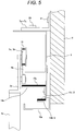
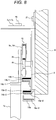
- a heat insulating material 15a is mounted over and fixed to the top surface of a buffer material receiving member 14a. Further, a heat insulating material 15b-2 is also mounted over and fixed to the top surface of a buffer material receiving member 14b-2 formed in a pocket 3.
- a heat insulating material 15b-1 is mounted over and fixed to the top surface of a buffer material receiving member 14b-1. Further, a heat insulating material 15b-2 is also mounted over and fixed to the top surface of a buffer material receiving member 14b-2 formed in a pocket 3.
- a heat insulating material Various kinds of materials can be used as a heat insulating material but an inorganic material is desirably used.
- an inorganic material For example, calcium silicate, ceramics, alumina, or the like can be used by being molded and processed into an appropriate shape. Then such an inorganic material is melted and processed to a fibrous form and subjected to thermocompression bonding and thus a heat insulating material is produced. Otherwise, a heat insulating material can be produced by processing into a porous form.
- a heat insulating material itself can absorb a melting buffer material 13 and the melting buffer material 13 can be fixed to the surfaces of the heat insulating materials 15a, 15b-1, and 15b-2.
- the buffer material receiving members 14a, 14b-1, and 14b-2 comprise a ferrous material (stainless steel for example) and the heat insulating materials 15a, 15b-1, and 15b-2 are assembled and fixed to the top surfaces of them.
- the temperature rise of the heat insulating materials 15a, 15b-1, and 15b-2 therefore can be smaller than the temperature rise of the buffer material receiving members 14a, 14b-1, and 14b-2 comprising a metal.
- the temperature rise is kept low and hence the danger of igniting the buffer material 13 more reduces than the first embodiment.
- the temperature of the heat insulating material 15b-2 of the buffer material receiving member 14b-2 located on the side lower than the buffer material receiving members 14a and 14b-1 is kept low, the heat radiation of them can be kept low and the temperature rise of the buffer material receiving member 14b-1 can be inhibited.
- a heat insulating material is mounted over and fixed to buffer material receiving members 14a, 14b-1, and 14b-2 in the present embodiment, it is possible to: install a heat insulating material at least over the top surfaces of the buffer material receiving members 14a and 14b-1; and if necessary install a heat insulating material over the top surface of the buffer material receiving member 14b-2.
- a heat insulating material 15b-2 has to be installed over the buffer material receiving member 14b-2.
- a heat insulating material is mounted over and fixed to at least the top surfaces of the buffer material receiving members 14a and 14b-1 and if necessary the top surface of the buffer material receiving member 14b-2, it is possible to: keep the surface temperatures of the respective heat insulating materials low; and further reduce the danger of igniting a melting buffer material.
- a third embodiment according to the present invention is explained hereunder.
- a reference numeral identical to the first embodiment and the second embodiment represents an identical constituent component or a constituent component having a similar function.
- the third embodiment is the case of fixing a radiation inhibiting material to the bottom surfaces of buffer material receiving members 14a, 14b-1, and 14b-2 and the bottom inner surfaces of gateway upper frames 10a and 10b.
- a radiation inhibiting material 16a is fixed to the bottom surface of a buffer material receiving member 14a.
- a radiation inhibiting material 16b-2 is also mounted over and fixed to the bottom surface of a buffer material receiving member 14b-2 formed in a pocket 3.
- the radiation inhibiting materials 16a and 16b-2 have the function of reflecting radiant heat.
- a radiation inhibiting material 16c-1 is fixed also to the bottom inner surface of a gateway upper frame 10a and the radiation inhibiting material 16c-1 has the function of inhibiting radiant heat from radiating.
- a radiation inhibiting material 16b-1 is fixed to the bottom surface of a buffer material receiving member 14b-1. Further, a radiation inhibiting material 16b-2 is also mounted over and fixed to the bottom surface of a buffer material receiving member 14b-2 formed in a pocket 3. The radiation inhibiting materials 16b-1 and 16b-2 have the function of reflecting radiant heat. Further, likewise, a radiation inhibiting material 16c-2 is fixed also to the bottom inner surface of a gateway upper frame 10b and the radiation inhibiting material 16c-2 has the function of inhibiting radiant heat from radiating.
- the buffer material receiving members 14a, 14b-1, and 14b-2 and the gateway upper frames 10a and 10b comprise a ferrous material (stainless steel, for example); and the radiation inhibiting materials 16a, 16b-1, 16b-2, 16c-1, and 16c-2 are assembled and fixed to the bottom surfaces of the buffer material receiving members 14a, 14b-1, and 14b-2 and the bottom inner surfaces of the gateway upper frames 10a and 10b.
- the radiation inhibiting materials 16a, 16b-1, 16b-2, 16c-1, and 16c-2 in comparison with the temperature rise in the case of only the buffer material receiving members 14a, 14b-1, and 14b-2 comprising a metal shown in Fig. 1 .
- the temperature rise is inhibited and hence the danger of igniting a buffer material 13 reduces.
- the radiation of radiant heat is inhibited by the radiation inhibiting materials 16c-1 and 16c-2 of the gateway upper frames 10a and 10b and hence the temperature rise of the buffer material receiving members 14a, 14b-1, and 14b-2 can be inhibited.
- the radiation inhibiting materials are fixed to the buffer material receiving members 14a, 14b-1, and 14b-2 and the gateway upper frames 10a and 10b in the present embodiment, it is possible to: install a radiation inhibiting material at least over the bottom surfaces of the buffer material receiving members 14a and 14b-1; and if necessary install a radiation inhibiting material over the bottom surface of the buffer material receiving member 14b-2 and the bottom inner surfaces of the gateway upper frames 10a and 10b.
- a heat radiation inhibiting material 16b-2 has to be installed over the buffer material receiving member 14b-2.
- a buffer material receiving member 14b-1 is installed in each of the opening and closing doors 1a and 1b individually. Also by such a structure, it is possible to receive a melting buffer material 13 by a buffer material receiving member 14b-1 and inhibit the melting buffer material 13 from dropping over gateway upper frames 10a and 10b of high temperatures and hence the danger of generating fire in a hoistway reduces and an opening and closing door excellent in fire-resistance performance is obtained.
- the buffer material receiving member 14b-1 is not required to be separated unlike a buffer material receiving member 14a in the first to third embodiments and may be a buffer material receiving member 14b-1 of a continuous shape.
- an opening and closing door of a two-leaved center-swing type it is advantageous to: omit a buffer material receiving member 14b-1; and form only a buffer material receiving member 14b-2 by bending the lowermost end of a pocket 3 toward the side of opening and closing doors 1a and 1b. It is possible thereby to form the buffer material receiving member 14b-2 integrally and continuously over the two opening and closing doors 1a and 1b.
- the functions and effects of: being able to omit the buffer material receiving member 14b-1; facilitating operations during attaching; and being able to save material costs can be obtained.
- a configuration of: arranging a buffer material receiving member extending in the directions of shifting a hanger roller between the upper part of a gateway upper frame of a platform gateway and the hanger roller; and receiving a melting buffer material by the buffer material receiving member is adopted. It is possible thereby to receive the melting buffer material by the buffer material receiving member and inhibit the melting buffer material from dropping over the gateway upper frame of a high temperature and hence the danger of generating fire in a hoistway reduces and the fire-resistance performance comes to be excellent.
- the present invention is not limited to the embodiments stated above and includes various modified examples.
- the above embodiments are explained in detail in order to make the present invention easy to understand and the present invention is not necessarily limited to the cases having all the configurations explained above.
Landscapes
- Elevator Door Apparatuses (AREA)
- Special Wing (AREA)
Claims (9)
- Aufzugvorrichtung, die Folgendes umfasst:einen vertikalen Rahmen (12) an der Seite zum Öffnen der Tür, einen vertikalen Rahmen (11) an der Seite zum Schließen der Tür und einen oberen Zugangsrahmen (10), der die oberen Teile der beiden vertikalen Rahmen verbindet, wobei diese einen Plattformzugang bei einer Aufzugplattform bilden,eine Tür zum Öffnen und Schließen, um den Plattformzugang zu öffnen und zu schließen, die so konfiguriert ist, dass eine Türaufhängung (2a, 2b), die an einer Aufhängungsschiene (4a, 4b) aufgehängt ist, die an einem Aufzugschacht (8) befestigt ist, an dem oberen Teil der Tür zum Öffnen und Schließen installiert ist, undeine Aufhängungsrolle (5a-d), die über die Aufhängungsschiene (4a, 4b) rollt und ein Stoßdämpfermaterial (13) aufweist, das ein Kunstharz über einer Rollfläche umfasst, die an der Türaufhängung (2a, 2b) installiert ist,dadurch gekennzeichnet, dass:
ein Stoßdämpfermaterial-Aufnahmeelement (14a, 14b-1, 14b-2), das sich in die Verschieberichtungen der Aufhängungsrolle (5a-d) erstreckt, das das Stoßdämpfermaterial (13) in einem Schmelzzustand aufnimmt und verhindert, dass das Stoßdämpfermaterial (13) über den oberen Zugangsrahmen (10) herabtropft, zwischen dem oberen Teil des oberen Zugangsrahmens (10) und der Aufhängungsrolle (5a-d) angeordnet ist. - Aufzugvorrichtung nach Anspruch 1, wobei:die Tür zum Öffnen und Schließen eine erste Tür (1a) zum Öffnen und Schließen und eine zweite Tür (1b) zum Öffnen und Schließen umfasst; undin dem Zustand des Schließens der ersten Tür (1a) zum Öffnen und Schließen und der zweiten Tür (1b) zum Öffnen und Schließen das Stoßdämpfermaterial-Aufnahmeelement (14a, 14b-1, 14b-2) ein Stoßdämpfermaterial- Aufnahmeelement für die erste Tür zum Öffnen und Schließen, das sich in den Bereich erstreckt, in dem die Aufhängungsrolle (5a-d) der ersten Tür (1a) zum Öffnen und Schließen angeordnet ist, und ein Stoßdämpfermaterial-Aufnahmeelement (14a, 14b-1, 14b-2) für die zweite Tür zum Öffnen und Schließen, das sich in den Bereich erstreckt, in dem die Aufhängungsrolle (5a-d) der zweiten Tür (1b) zum Öffnen und Schließen angeordnet ist, umfasst.
- Aufzugvorrichtung nach Anspruch 2, wobei:die Tür zum Öffnen und Schließen eine zweiflügelige Tür zum Öffnen und Schließen des Typs ist, der sich in einer Richtung öffnet, die so konfiguriert ist, dass sich die erste Tür (1a) zum Öffnen und Schließen und die zweite Tür (1b) zum Öffnen und Schließen in derselben Richtung öffnen und sich in einer anderen selben Richtung schließen und dass darüber hinaus die erste Tür (1a) zum Öffnen und Schließen und die zweite Tür (1b) zum Öffnen und Schließen in einem geöffneten Zustand übereinanderliegen; undin dem Zustand des Schließens der ersten Tür (1a) zum Öffnen und Schließen und der zweiten Tür (1b) zum Öffnen und Schließen das Stoßdämpfermaterial-Aufnahmeelement (14a, 14b-1, 14b-2) ein Stoßdämpfermaterial- Aufnahmeelement für die erste Tür zum Öffnen und Schließen, das sich in den Bereich erstreckt, in dem die Aufhängungsrolle (5a-d) der ersten Tür (1a) zum Öffnen und Schließen angeordnet ist, und ein Stoßdämpfermaterial-Aufnahmeelement für die zweite Tür zum Öffnen und Schließen, das von dem Stoßdämpfermaterial-Aufnahmeelement für die erste Tür getrennt ist und sich in den Bereich erstreckt, in dem die Aufhängungsrolle (5a-d) der zweiten Tür (1b) zum Öffnen und Schließen angeordnet ist, umfasst.
- Aufzugvorrichtung nach Anspruch 3, wobei eine Tasche (3), an der die Aufhängungsschiene (4a, 4b) befestigt ist, an der Innenwandfläche des Aufzugschachts (8) befestigt ist und das Stoßdämpfermaterial-Aufnahmeelement für die erste Tür zum Öffnen und Schließen und das Stoßdämpfermaterial-Aufnahmeelement für die zweite Tür zum Öffnen und Schließen an der Tasche (3) befestigt sind.
- Aufzugvorrichtung nach Anspruch 4, wobei das Stoßdämpfermaterial-Aufnahmeelement für die erste Tür zum Öffnen und Schließen und das Stoßdämpfermaterial-Aufnahmeelement für die zweite Tür zum Öffnen und Schließen an einem Teil ausgebildet sind, an dem das untere Ende der Tasche (3) gebogen ist.
- Aufzugvorrichtung nach Anspruch 5, wobei ein wärmeisolierendes Material (15a-c) über den oberen Oberflächen des Stoßdämpfermaterial-Aufnahmeelements der ersten Tür zum Öffnen und Schließen und des Stoßdämpfermaterial-Aufnahmeelements der zweiten Tür zum Öffnen und Schließen installiert ist, wobei ein Material (16a, 16b-1, 16b-2) zum Verhindern von Wärmestrahlung über den unteren Oberflächen des Stoßdämpfermaterial-Aufnahmeelements der ersten Tür zum Öffnen und Schließen und des Stoßdämpfermaterial-Aufnahmeelements der zweiten Tür zum Öffnen und Schließen installiert ist oder wobei ein wärmeisolierendes Material (15a-c) über den oberen Oberflächen installiert ist und ein Material (16a, 16b-1, 16b-2) zum Verhindern von Wärmestrahlung über den unteren Oberflächen des Stoßdämpfermaterial-Aufnahmeelements der ersten Tür zum Öffnen und Schließen und des Stoßdämpfermaterial-Aufnahmeelements der zweiten Tür zum Öffnen und Schließen installiert ist.
- Aufzugvorrichtung nach Anspruch 2, wobei:die Tür zum Öffnen und Schließen eine zweiflügelige Tür zum Öffnen und Schließen des Typs ist, der zur Mitte schwingt, die so konfiguriert ist, dass sich die erste Tür (1a) zum Öffnen und Schließen und die zweite Tür (1b) zum Öffnen und Schließen in entgegengesetzten Richtungen öffnen und schließen; undin dem Zustand des Schließens der ersten Tür (1a) zum Öffnen und Schließen und der zweiten Tür (1b) zum Öffnen und Schließen das Stoßdämpfermaterial-Aufnahmeelement (14a, 14b-1, 14b-2) entweder in dem Bereich, in dem die Aufhängungsrolle (5a-d) der ersten Tür (1a) zum Öffnen und Schließen angeordnet ist und in dem Bereich, in dem die Aufhängungsrolle (5a-d) der zweiten Tür (1b) zum Öffnen und Schließen angeordnet ist, getrennt installiert ist, oder sich über den Bereich, in dem die Aufhängungsrolle (5a-d) der ersten Tür (1a) zum Öffnen und Schließen angeordnet ist und über den Bereich, in dem die Aufhängungsrolle (5a-d) der zweiten Tür (1b) zum Öffnen und Schließen angeordnet ist, einteilig und durchgehend erstreckt.
- Aufzugvorrichtung nach Anspruch 7, wobei eine Tasche (3), an der die Aufhängungsschiene (4a, 4b) befestigt ist, an der Innenwandfläche des Aufzugschachts (8) befestigt ist, und wobei das Stoßdämpfermaterial-Aufnahmeelement (14a, 14b-1, 14b-2) an einem Teil ausgebildet ist, an dem das untere Ende der Tasche (3) gebogen ist.
- Aufzugvorrichtung nach Anspruch 7, wobei ein wärmeisolierendes Material (15a-c) über der oberen Oberfläche des Stoßdämpfermaterial-Aufnahmeelements (14a, 14b-1, 14b-2) installiert ist, ein Material (16a, 16b-1, 16b-2) zum Verhindern von Wärmestrahlung über der unteren Oberfläche des Stoßdämpfermaterial-Aufnahmeelements (14a, 14b-1, 14b-2) installiert ist oder ein wärmeisolierendes Material (15a-c) über der oberen Oberfläche installiert ist und ein Material (16a, 16b-1, 16b-2) zum Verhindern von Wärmestrahlung über der unteren Oberfläche des Stoßdämpfermaterial-Aufnahmeelements (14a, 14b-1, 14b-2) installiert ist.
Applications Claiming Priority (1)
| Application Number | Priority Date | Filing Date | Title |
|---|---|---|---|
| PCT/JP2014/077857 WO2016063333A1 (ja) | 2014-10-20 | 2014-10-20 | エレベータ装置 |
Publications (3)
| Publication Number | Publication Date |
|---|---|
| EP3210927A1 EP3210927A1 (de) | 2017-08-30 |
| EP3210927A4 EP3210927A4 (de) | 2018-07-18 |
| EP3210927B1 true EP3210927B1 (de) | 2020-09-16 |
Family
ID=55760408
Family Applications (1)
| Application Number | Title | Priority Date | Filing Date |
|---|---|---|---|
| EP14904518.9A Active EP3210927B1 (de) | 2014-10-20 | 2014-10-20 | Aufzugsvorrichtung |
Country Status (5)
| Country | Link |
|---|---|
| EP (1) | EP3210927B1 (de) |
| JP (1) | JP6235160B2 (de) |
| KR (1) | KR101920583B1 (de) |
| CN (1) | CN107074503B (de) |
| WO (1) | WO2016063333A1 (de) |
Families Citing this family (3)
| Publication number | Priority date | Publication date | Assignee | Title |
|---|---|---|---|---|
| DE112018007835T5 (de) * | 2018-07-18 | 2021-04-01 | Mitsubishi Electric Corporation | Aufzugsschachttürvorrichtung |
| JP7171851B1 (ja) * | 2021-08-03 | 2022-11-15 | 東芝エレベータ株式会社 | エレベータの乗場装置 |
| USD1115392S1 (en) | 2025-04-16 | 2026-03-03 | David Quessenberry | Wedge pillow |
Family Cites Families (7)
| Publication number | Priority date | Publication date | Assignee | Title |
|---|---|---|---|---|
| JPS63178284U (de) * | 1987-05-07 | 1988-11-18 | ||
| KR100524283B1 (ko) * | 2000-07-17 | 2005-10-28 | 가부시끼가이샤 도시바 | 엘리베이터 승강장의 도어 행거 장치 |
| JP4674974B2 (ja) * | 2001-01-24 | 2011-04-20 | 東芝エレベータ株式会社 | エレベータ乗場の扉装置 |
| CN200971281Y (zh) * | 2006-11-22 | 2007-11-07 | 杭州西子孚信科技有限公司 | 电梯防火隔热层门 |
| KR101203759B1 (ko) * | 2007-12-06 | 2012-11-21 | 미쓰비시덴키 가부시키가이샤 | 엘리베이터 승강장 도어 |
| WO2010042098A1 (en) * | 2008-10-06 | 2010-04-15 | Otis Elevator Company | Thermal barriers of elevator door roller and rail |
| KR101206547B1 (ko) * | 2010-10-07 | 2012-11-29 | 오티스 엘리베이터 컴파니 | 엘리베이터 방화 도어의 발화 방지 구조 |
-
2014
- 2014-10-20 EP EP14904518.9A patent/EP3210927B1/de active Active
- 2014-10-20 JP JP2016554964A patent/JP6235160B2/ja active Active
- 2014-10-20 CN CN201480082748.9A patent/CN107074503B/zh active Active
- 2014-10-20 KR KR1020177010187A patent/KR101920583B1/ko not_active Expired - Fee Related
- 2014-10-20 WO PCT/JP2014/077857 patent/WO2016063333A1/ja not_active Ceased
Non-Patent Citations (1)
| Title |
|---|
| None * |
Also Published As
| Publication number | Publication date |
|---|---|
| CN107074503A (zh) | 2017-08-18 |
| JPWO2016063333A1 (ja) | 2017-06-01 |
| WO2016063333A1 (ja) | 2016-04-28 |
| EP3210927A4 (de) | 2018-07-18 |
| EP3210927A1 (de) | 2017-08-30 |
| JP6235160B2 (ja) | 2017-11-22 |
| KR101920583B1 (ko) | 2018-11-20 |
| CN107074503B (zh) | 2018-11-27 |
| KR20170058974A (ko) | 2017-05-29 |
Similar Documents
| Publication | Publication Date | Title |
|---|---|---|
| EP3210927B1 (de) | Aufzugsvorrichtung | |
| JP2502182B2 (ja) | エレベ―タ―乗場ドア装置 | |
| TW491809B (en) | Elevator door and door hanger device | |
| JP7317658B2 (ja) | 引戸式の防火戸 | |
| JPH04153190A (ja) | エレベーター乗場ドア装置 | |
| US5988321A (en) | Elevator door apparatus | |
| CN100408462C (zh) | 电梯乘梯处的门及门吊挂装置 | |
| JP6214198B2 (ja) | 開閉装置 | |
| KR100686662B1 (ko) | 화염방지장치를 구비한 엘리베이터 승강장 도어 | |
| JP2022054301A (ja) | 引戸装置 | |
| CN105905767A (zh) | 电梯的候梯厅门装置 | |
| JP4674974B2 (ja) | エレベータ乗場の扉装置 | |
| JP5174897B2 (ja) | エレベータの乗場出入口装置 | |
| JP6271133B2 (ja) | 窓シャッター装置 | |
| HK1236911A1 (en) | Elevator apparatus | |
| JP5645310B2 (ja) | エレベータのドア装置 | |
| HK1236911B (zh) | 电梯设备 | |
| JP5368842B2 (ja) | パネルシャッタ | |
| JP2022054300A (ja) | ドア | |
| JP6323983B2 (ja) | 開閉装置 | |
| JP7564751B2 (ja) | 防火性能が向上されたパネル構造 | |
| JPH04153189A (ja) | エレベータ乗場ドア装置 | |
| KR101194006B1 (ko) | 단조 가열로의 린텔 구조 | |
| JP2014202048A (ja) | 開閉装置 |
Legal Events
| Date | Code | Title | Description |
|---|---|---|---|
| STAA | Information on the status of an ep patent application or granted ep patent |
Free format text: STATUS: THE INTERNATIONAL PUBLICATION HAS BEEN MADE |
|
| PUAI | Public reference made under article 153(3) epc to a published international application that has entered the european phase |
Free format text: ORIGINAL CODE: 0009012 |
|
| STAA | Information on the status of an ep patent application or granted ep patent |
Free format text: STATUS: REQUEST FOR EXAMINATION WAS MADE |
|
| 17P | Request for examination filed |
Effective date: 20170522 |
|
| AK | Designated contracting states |
Kind code of ref document: A1 Designated state(s): AL AT BE BG CH CY CZ DE DK EE ES FI FR GB GR HR HU IE IS IT LI LT LU LV MC MK MT NL NO PL PT RO RS SE SI SK SM TR |
|
| AX | Request for extension of the european patent |
Extension state: BA ME |
|
| DAX | Request for extension of the european patent (deleted) | ||
| RIC1 | Information provided on ipc code assigned before grant |
Ipc: B66B 13/30 20060101AFI20180606BHEP |
|
| A4 | Supplementary search report drawn up and despatched |
Effective date: 20180614 |
|
| GRAP | Despatch of communication of intention to grant a patent |
Free format text: ORIGINAL CODE: EPIDOSNIGR1 |
|
| STAA | Information on the status of an ep patent application or granted ep patent |
Free format text: STATUS: GRANT OF PATENT IS INTENDED |
|
| INTG | Intention to grant announced |
Effective date: 20200330 |
|
| GRAS | Grant fee paid |
Free format text: ORIGINAL CODE: EPIDOSNIGR3 |
|
| GRAA | (expected) grant |
Free format text: ORIGINAL CODE: 0009210 |
|
| STAA | Information on the status of an ep patent application or granted ep patent |
Free format text: STATUS: THE PATENT HAS BEEN GRANTED |
|
| AK | Designated contracting states |
Kind code of ref document: B1 Designated state(s): AL AT BE BG CH CY CZ DE DK EE ES FI FR GB GR HR HU IE IS IT LI LT LU LV MC MK MT NL NO PL PT RO RS SE SI SK SM TR |
|
| REG | Reference to a national code |
Ref country code: GB Ref legal event code: FG4D |
|
| REG | Reference to a national code |
Ref country code: CH Ref legal event code: EP |
|
| REG | Reference to a national code |
Ref country code: DE Ref legal event code: R096 Ref document number: 602014070361 Country of ref document: DE |
|
| REG | Reference to a national code |
Ref country code: IE Ref legal event code: FG4D |
|
| REG | Reference to a national code |
Ref country code: AT Ref legal event code: REF Ref document number: 1314017 Country of ref document: AT Kind code of ref document: T Effective date: 20201015 |
|
| PG25 | Lapsed in a contracting state [announced via postgrant information from national office to epo] |
Ref country code: BG Free format text: LAPSE BECAUSE OF FAILURE TO SUBMIT A TRANSLATION OF THE DESCRIPTION OR TO PAY THE FEE WITHIN THE PRESCRIBED TIME-LIMIT Effective date: 20201216 Ref country code: NO Free format text: LAPSE BECAUSE OF FAILURE TO SUBMIT A TRANSLATION OF THE DESCRIPTION OR TO PAY THE FEE WITHIN THE PRESCRIBED TIME-LIMIT Effective date: 20201216 Ref country code: GR Free format text: LAPSE BECAUSE OF FAILURE TO SUBMIT A TRANSLATION OF THE DESCRIPTION OR TO PAY THE FEE WITHIN THE PRESCRIBED TIME-LIMIT Effective date: 20201217 Ref country code: FI Free format text: LAPSE BECAUSE OF FAILURE TO SUBMIT A TRANSLATION OF THE DESCRIPTION OR TO PAY THE FEE WITHIN THE PRESCRIBED TIME-LIMIT Effective date: 20200916 Ref country code: SE Free format text: LAPSE BECAUSE OF FAILURE TO SUBMIT A TRANSLATION OF THE DESCRIPTION OR TO PAY THE FEE WITHIN THE PRESCRIBED TIME-LIMIT Effective date: 20200916 Ref country code: HR Free format text: LAPSE BECAUSE OF FAILURE TO SUBMIT A TRANSLATION OF THE DESCRIPTION OR TO PAY THE FEE WITHIN THE PRESCRIBED TIME-LIMIT Effective date: 20200916 |
|
| REG | Reference to a national code |
Ref country code: AT Ref legal event code: MK05 Ref document number: 1314017 Country of ref document: AT Kind code of ref document: T Effective date: 20200916 |
|
| REG | Reference to a national code |
Ref country code: NL Ref legal event code: MP Effective date: 20200916 |
|
| PG25 | Lapsed in a contracting state [announced via postgrant information from national office to epo] |
Ref country code: LV Free format text: LAPSE BECAUSE OF FAILURE TO SUBMIT A TRANSLATION OF THE DESCRIPTION OR TO PAY THE FEE WITHIN THE PRESCRIBED TIME-LIMIT Effective date: 20200916 Ref country code: RS Free format text: LAPSE BECAUSE OF FAILURE TO SUBMIT A TRANSLATION OF THE DESCRIPTION OR TO PAY THE FEE WITHIN THE PRESCRIBED TIME-LIMIT Effective date: 20200916 |
|
| REG | Reference to a national code |
Ref country code: LT Ref legal event code: MG4D |
|
| PG25 | Lapsed in a contracting state [announced via postgrant information from national office to epo] |
Ref country code: CZ Free format text: LAPSE BECAUSE OF FAILURE TO SUBMIT A TRANSLATION OF THE DESCRIPTION OR TO PAY THE FEE WITHIN THE PRESCRIBED TIME-LIMIT Effective date: 20200916 Ref country code: PT Free format text: LAPSE BECAUSE OF FAILURE TO SUBMIT A TRANSLATION OF THE DESCRIPTION OR TO PAY THE FEE WITHIN THE PRESCRIBED TIME-LIMIT Effective date: 20210118 Ref country code: LT Free format text: LAPSE BECAUSE OF FAILURE TO SUBMIT A TRANSLATION OF THE DESCRIPTION OR TO PAY THE FEE WITHIN THE PRESCRIBED TIME-LIMIT Effective date: 20200916 Ref country code: EE Free format text: LAPSE BECAUSE OF FAILURE TO SUBMIT A TRANSLATION OF THE DESCRIPTION OR TO PAY THE FEE WITHIN THE PRESCRIBED TIME-LIMIT Effective date: 20200916 Ref country code: SM Free format text: LAPSE BECAUSE OF FAILURE TO SUBMIT A TRANSLATION OF THE DESCRIPTION OR TO PAY THE FEE WITHIN THE PRESCRIBED TIME-LIMIT Effective date: 20200916 Ref country code: RO Free format text: LAPSE BECAUSE OF FAILURE TO SUBMIT A TRANSLATION OF THE DESCRIPTION OR TO PAY THE FEE WITHIN THE PRESCRIBED TIME-LIMIT Effective date: 20200916 |
|
| PG25 | Lapsed in a contracting state [announced via postgrant information from national office to epo] |
Ref country code: ES Free format text: LAPSE BECAUSE OF FAILURE TO SUBMIT A TRANSLATION OF THE DESCRIPTION OR TO PAY THE FEE WITHIN THE PRESCRIBED TIME-LIMIT Effective date: 20200916 Ref country code: AT Free format text: LAPSE BECAUSE OF FAILURE TO SUBMIT A TRANSLATION OF THE DESCRIPTION OR TO PAY THE FEE WITHIN THE PRESCRIBED TIME-LIMIT Effective date: 20200916 Ref country code: AL Free format text: LAPSE BECAUSE OF FAILURE TO SUBMIT A TRANSLATION OF THE DESCRIPTION OR TO PAY THE FEE WITHIN THE PRESCRIBED TIME-LIMIT Effective date: 20200916 Ref country code: PL Free format text: LAPSE BECAUSE OF FAILURE TO SUBMIT A TRANSLATION OF THE DESCRIPTION OR TO PAY THE FEE WITHIN THE PRESCRIBED TIME-LIMIT Effective date: 20200916 Ref country code: IS Free format text: LAPSE BECAUSE OF FAILURE TO SUBMIT A TRANSLATION OF THE DESCRIPTION OR TO PAY THE FEE WITHIN THE PRESCRIBED TIME-LIMIT Effective date: 20210116 |
|
| REG | Reference to a national code |
Ref country code: CH Ref legal event code: PL |
|
| REG | Reference to a national code |
Ref country code: DE Ref legal event code: R097 Ref document number: 602014070361 Country of ref document: DE |
|
| PG25 | Lapsed in a contracting state [announced via postgrant information from national office to epo] |
Ref country code: LU Free format text: LAPSE BECAUSE OF NON-PAYMENT OF DUE FEES Effective date: 20201020 Ref country code: MC Free format text: LAPSE BECAUSE OF FAILURE TO SUBMIT A TRANSLATION OF THE DESCRIPTION OR TO PAY THE FEE WITHIN THE PRESCRIBED TIME-LIMIT Effective date: 20200916 Ref country code: SK Free format text: LAPSE BECAUSE OF FAILURE TO SUBMIT A TRANSLATION OF THE DESCRIPTION OR TO PAY THE FEE WITHIN THE PRESCRIBED TIME-LIMIT Effective date: 20200916 |
|
| REG | Reference to a national code |
Ref country code: BE Ref legal event code: MM Effective date: 20201031 |
|
| PLBE | No opposition filed within time limit |
Free format text: ORIGINAL CODE: 0009261 |
|
| STAA | Information on the status of an ep patent application or granted ep patent |
Free format text: STATUS: NO OPPOSITION FILED WITHIN TIME LIMIT |
|
| 26N | No opposition filed |
Effective date: 20210617 |
|
| GBPC | Gb: european patent ceased through non-payment of renewal fee |
Effective date: 20201216 |
|
| PG25 | Lapsed in a contracting state [announced via postgrant information from national office to epo] |
Ref country code: SI Free format text: LAPSE BECAUSE OF FAILURE TO SUBMIT A TRANSLATION OF THE DESCRIPTION OR TO PAY THE FEE WITHIN THE PRESCRIBED TIME-LIMIT Effective date: 20200916 Ref country code: LI Free format text: LAPSE BECAUSE OF NON-PAYMENT OF DUE FEES Effective date: 20201031 Ref country code: BE Free format text: LAPSE BECAUSE OF NON-PAYMENT OF DUE FEES Effective date: 20201031 Ref country code: DK Free format text: LAPSE BECAUSE OF FAILURE TO SUBMIT A TRANSLATION OF THE DESCRIPTION OR TO PAY THE FEE WITHIN THE PRESCRIBED TIME-LIMIT Effective date: 20200916 Ref country code: CH Free format text: LAPSE BECAUSE OF NON-PAYMENT OF DUE FEES Effective date: 20201031 |
|
| PG25 | Lapsed in a contracting state [announced via postgrant information from national office to epo] |
Ref country code: IT Free format text: LAPSE BECAUSE OF FAILURE TO SUBMIT A TRANSLATION OF THE DESCRIPTION OR TO PAY THE FEE WITHIN THE PRESCRIBED TIME-LIMIT Effective date: 20200916 Ref country code: IE Free format text: LAPSE BECAUSE OF NON-PAYMENT OF DUE FEES Effective date: 20201020 |
|
| PG25 | Lapsed in a contracting state [announced via postgrant information from national office to epo] |
Ref country code: GB Free format text: LAPSE BECAUSE OF NON-PAYMENT OF DUE FEES Effective date: 20201216 |
|
| PG25 | Lapsed in a contracting state [announced via postgrant information from national office to epo] |
Ref country code: IS Free format text: LAPSE BECAUSE OF FAILURE TO SUBMIT A TRANSLATION OF THE DESCRIPTION OR TO PAY THE FEE WITHIN THE PRESCRIBED TIME-LIMIT Effective date: 20210116 Ref country code: TR Free format text: LAPSE BECAUSE OF FAILURE TO SUBMIT A TRANSLATION OF THE DESCRIPTION OR TO PAY THE FEE WITHIN THE PRESCRIBED TIME-LIMIT Effective date: 20200916 Ref country code: MT Free format text: LAPSE BECAUSE OF FAILURE TO SUBMIT A TRANSLATION OF THE DESCRIPTION OR TO PAY THE FEE WITHIN THE PRESCRIBED TIME-LIMIT Effective date: 20200916 Ref country code: CY Free format text: LAPSE BECAUSE OF FAILURE TO SUBMIT A TRANSLATION OF THE DESCRIPTION OR TO PAY THE FEE WITHIN THE PRESCRIBED TIME-LIMIT Effective date: 20200916 |
|
| PG25 | Lapsed in a contracting state [announced via postgrant information from national office to epo] |
Ref country code: MK Free format text: LAPSE BECAUSE OF FAILURE TO SUBMIT A TRANSLATION OF THE DESCRIPTION OR TO PAY THE FEE WITHIN THE PRESCRIBED TIME-LIMIT Effective date: 20200916 |
|
| PG25 | Lapsed in a contracting state [announced via postgrant information from national office to epo] |
Ref country code: NL Free format text: LAPSE BECAUSE OF NON-PAYMENT OF DUE FEES Effective date: 20200923 |
|
| PGFP | Annual fee paid to national office [announced via postgrant information from national office to epo] |
Ref country code: FR Payment date: 20250923 Year of fee payment: 12 |
|
| PGFP | Annual fee paid to national office [announced via postgrant information from national office to epo] |
Ref country code: DE Payment date: 20250923 Year of fee payment: 12 |