EP3210929A1 - Lastaufnehmendes bauteil der anschlag-, zurr- und/oder hebetechnik mit einem kunststoff-metall-verbundsystem - Google Patents
Lastaufnehmendes bauteil der anschlag-, zurr- und/oder hebetechnik mit einem kunststoff-metall-verbundsystem Download PDFInfo
- Publication number
- EP3210929A1 EP3210929A1 EP17156523.7A EP17156523A EP3210929A1 EP 3210929 A1 EP3210929 A1 EP 3210929A1 EP 17156523 A EP17156523 A EP 17156523A EP 3210929 A1 EP3210929 A1 EP 3210929A1
- Authority
- EP
- European Patent Office
- Prior art keywords
- load
- component
- fiber
- outer shell
- plastic
- Prior art date
- Legal status (The legal status is an assumption and is not a legal conclusion. Google has not performed a legal analysis and makes no representation as to the accuracy of the status listed.)
- Granted
Links
Images

Classifications
-
- B—PERFORMING OPERATIONS; TRANSPORTING
- B66—HOISTING; LIFTING; HAULING
- B66C—CRANES; LOAD-ENGAGING ELEMENTS OR DEVICES FOR CRANES, CAPSTANS, WINCHES, OR TACKLES
- B66C1/00—Load-engaging elements or devices attached to lifting or lowering gear of cranes or adapted for connection therewith for transmitting lifting forces to articles or groups of articles
- B66C1/10—Load-engaging elements or devices attached to lifting or lowering gear of cranes or adapted for connection therewith for transmitting lifting forces to articles or groups of articles by mechanical means
- B66C1/22—Rigid members, e.g. L-shaped members, with parts engaging the under surface of the loads; Crane hooks
- B66C1/34—Crane hooks
-
- F—MECHANICAL ENGINEERING; LIGHTING; HEATING; WEAPONS; BLASTING
- F16—ENGINEERING ELEMENTS AND UNITS; GENERAL MEASURES FOR PRODUCING AND MAINTAINING EFFECTIVE FUNCTIONING OF MACHINES OR INSTALLATIONS; THERMAL INSULATION IN GENERAL
- F16B—DEVICES FOR FASTENING OR SECURING CONSTRUCTIONAL ELEMENTS OR MACHINE PARTS TOGETHER, e.g. NAILS, BOLTS, CIRCLIPS, CLAMPS, CLIPS OR WEDGES; JOINTS OR JOINTING
- F16B45/00—Hooks; Eyes
-
- F—MECHANICAL ENGINEERING; LIGHTING; HEATING; WEAPONS; BLASTING
- F16—ENGINEERING ELEMENTS AND UNITS; GENERAL MEASURES FOR PRODUCING AND MAINTAINING EFFECTIVE FUNCTIONING OF MACHINES OR INSTALLATIONS; THERMAL INSULATION IN GENERAL
- F16G—BELTS, CABLES, OR ROPES, PREDOMINANTLY USED FOR DRIVING PURPOSES; CHAINS; FITTINGS PREDOMINANTLY USED THEREFOR
- F16G13/00—Chains
- F16G13/12—Hauling- or hoisting-chains so called ornamental chains
-
- F—MECHANICAL ENGINEERING; LIGHTING; HEATING; WEAPONS; BLASTING
- F16—ENGINEERING ELEMENTS AND UNITS; GENERAL MEASURES FOR PRODUCING AND MAINTAINING EFFECTIVE FUNCTIONING OF MACHINES OR INSTALLATIONS; THERMAL INSULATION IN GENERAL
- F16G—BELTS, CABLES, OR ROPES, PREDOMINANTLY USED FOR DRIVING PURPOSES; CHAINS; FITTINGS PREDOMINANTLY USED THEREFOR
- F16G15/00—Chain couplings, Shackles; Chain joints; Chain links; Chain bushes
- F16G15/04—Quickly-detachable chain couplings; Shackles chain links with rapid junction means are classified according to the corresponding kind of chain
- F16G15/06—Shackles designed for attachment by joint pins to chain elements, e.g. D-shackles so called harp links; the D-chain links are classified according to the corresponding kind of chain
-
- F—MECHANICAL ENGINEERING; LIGHTING; HEATING; WEAPONS; BLASTING
- F16—ENGINEERING ELEMENTS AND UNITS; GENERAL MEASURES FOR PRODUCING AND MAINTAINING EFFECTIVE FUNCTIONING OF MACHINES OR INSTALLATIONS; THERMAL INSULATION IN GENERAL
- F16G—BELTS, CABLES, OR ROPES, PREDOMINANTLY USED FOR DRIVING PURPOSES; CHAINS; FITTINGS PREDOMINANTLY USED THEREFOR
- F16G15/00—Chain couplings, Shackles; Chain joints; Chain links; Chain bushes
- F16G15/12—Chain links
Definitions
- the invention relates to a load-absorbing component of the stop, lashing and / or lifting technique, with a plastic-metal composite system, which forms at least one load receiving portion for stopping and / or hanging a load and at least one connection portion for attachment of the component to another object ,
- Such a load-bearing component may be in the form of a shackle, ring, hook or in the form of a chain link, ring member or an eyelet.
- the load-receiving hook has an inner body of a metallic material, which is at least partially sheathed with a plastic material.
- the inner body is a flat, cut out of a board half-timbered body, which is coupled to a truss structure, the plastic body.
- the plastic-metal composite system extending from the load receiving portion to the connecting portion continuously, forming a support structure core of a fiber-plastic composite and at least one located on the load receiving portion and / or terminal portion outer shell made of a metal material.
- the components according to the invention are distinguished by a particularly low weight and a high load-bearing capacity.
- the core passes as a support structure, the forces from the load receiving section to the connection section.
- the outer shell on the load-receiving portion and / or connecting portion made of a metal material prevents too great a surface pressure when introducing a force from the stop means into the component and / or when the force is introduced into the other object.
- the outer shell distributes the force over a larger area, over which it is then directed into the core.
- the core at the areas not covered by the at least one outer shell may form the surface of the component.
- an outer shell made of a plastic material different from the core can also be present on the areas of the component not covered by the metallic outer shell.
- Such an outer shell is preferably also part of the fiber-plastic composite.
- the outer shell may for example consist of a highly elastic, shock-absorbing material and form, for example, a rubber armor.
- the outer shell may alternatively or cumulatively at least partially made of materials with special corrosion resistance when the component is used in corrosive environments.
- At least one fiber-directional element can be arranged in the core of the plastic-metal composite system.
- the fiber-directional element serves to ensure the intended fiber orientation, the position of the preform, or the layer stabilization of preimpregnated fiber layers, so-called prepregs, during the production process, and thus to achieve an optimum fiber orientation for the load case.
- the fiber-directional elements can follow the voltage curve in the core, in particular in their outer contour. In the vicinity of the fiber-directional element, the fibers are in particular aligned tangentially to the surface thereof.
- the fiber-directional element may in particular be conical or wedge-shaped. It is preferably located where the material thickness of the core relative to adjacent areas of the core is increased or where a loop connection of the fiber-plastic composite is provided to a metallic load-receiving element. At these thickened points during production, there is a risk that the intended fiber orientation is undefined, which could lead to a randomness of the fibers and thus to an only incomplete utilization of the fiber strength.
- the fiber-directing element may extend in the core away from a cylindrical opening of the component.
- the base of a wedge-shaped element is arranged on the cylindrical opening and the tip of the wedge-shaped element points away from the cylindrical opening.
- Such a cylindrical breakthrough for example, a through hole of the load receiving portion and / or connection section.
- the fiber-directional element can provide for a defined flow direction and fiber orientation around the cylindrical element and thus ensure a homogeneously curved loop connection.
- the outer shell may at least partially line a cylindrical opening of the component.
- Such an outer shell may, for example, form a flange portion around the cylindrical aperture, which is less sensitive to high surface pressures.
- electronic components can be integrated.
- these electronic components may be overmolded or infiltrated, i. they are firmly embedded in the core during the curing of the fiber-plastic composite.
- the electronic components may be data transmission devices, sensors, for example for the detection of at least one operating parameter such as a load state, the temperature and / or for detecting an operating state, such as the closing of a hook, carabiner or shackle.
- the electronic components may also comprise contactlessly readable memories with which such operating parameters and / or states as well as parameters for component identification and / or their maintenance are preferably stored updateable. Since the electronic components are firmly embedded in the core during curing of the fiber-plastic composite, you will not be accessible from outside the component later. This can prevent manipulation of the electronic components.
- the load receiving portion may be configured bow-shaped, wherein an inner surface of the load receiving portion is formed by the outer shell.
- a bow-shaped load-bearing section is found, for example, in shackles, carabiners, hooks, chain or ring links and eyelets.
- On the inner surface is a connecting member or a slippery stop, lifting or lashing such as a rope or a belt.
- the outer shell on the inner surface is to reduce the wear of the inner surface and distribute the force over a larger area on the core.
- the outer shell extends in the longitudinal direction of the bow-shaped load receiving section by more than a semicircular arc, ie by more than 180 °.
- a particularly stable component results when the fiber-plastic composite has continuous fibers.
- the endless fibers can be looped around a cylindrical opening or several openings of the component.
- the at least one looped breakthrough is in such a configuration within the area enclosed by the continuous fiber area.
- the openings may be part of the load receiving section, for example in ring links, chain links or eyelets and lifting points with eyelets.
- such openings can serve, for example, to receive a support or locking bolt or a clasp or latch.
- the load-bearing member 1 may be a shackle, a hook, a ring member, a chain link, an anchor point, a tensioner for straps, ropes or chains or a carabiner, to name just a few components of the stop, lashing and / or lifting technique.
- the component 1 has a load-receiving portion 2, on which a load by means of a stop means (not shown) posted and / or mounted.
- the component 1 further has a connection section 3, which serves to attach the component to another object.
- the component 1 may have a plurality of load receiving sections 2 and a plurality of connecting sections 3. It may, for example, as hook a further connection portion 3 'for attachment of a hook trap or a closure for the hook mouth.
- the component has a plastic-metal composite system 4.
- this composite system at least one plastic and at least one metal element are combined and processed together to achieve properties that the individual components of the composite system do not have in themselves.
- the plastic-metal composite system 4 has a core 5, which may form part of the outer surface of the component 1.
- the core itself is made of a fiber-plastic composite and forms a support structure 6, which guides a force acting on the load receiving portion 2 force 7 to the connection portion 3. From the connection section 3, it is introduced into the object attached there. The direction of the power flow can also change.
- the core 5 at least partially forms an outer surface 7 of the component 1.
- it may be coated on the outside with a shock-absorbing material which differs from the material of the core.
- This outer shell (not shown) may be part of the fiber-plastic composite.
- the core may be surrounded at least in sections, at least in sections, by an elastic rubber-like sheath so that impacts can not damage the component 1 or the core 5.
- the use of the component 1 in certain corrosive environments may further make it necessary to coat the core 5 with a protective layer of a layer which is corrosion-resistant to this environment. Such a layer may be part of the fiber-plastic composite.
- the plastic-metal composite system 4 furthermore has at least one outer shell 8, which is located at least on the load-receiving section 2 and / or on the connection section 3 and forms the outer surface 7 of the component 1 there.
- the outer shell 8 is made of a metal material.
- the load receiving section 2 and / or the connecting section 3 may have at least one cylindrical opening 9, which is lined at least in sections by the outer shell 8.
- the outer shell 8 serves to receive a force 7 acting on the outside of the component 1 and to pass it on to the core 5 over a larger area. At the same time, the outer shell 8 is intended to provide greater wear resistance against impact and abrasion.
- the outer shell 8 may at least partially form the inner surface 10 of the load receiving portion.
- the outer shell 8 may at least partially extend over the adjoining the inner surface side surfaces 11 of the component 1. In order to better protect the core 5 at this point, it can jump back somewhat with respect to the outer shell 8, for example, by a groove, so that a stop means mounted on the load receiving section 2 can not touch the core.
- the outer shell 8 may extend in the longitudinal direction 12 over a region 13 which occupies more than a semicircular arc, ie over 180 °.
- electronic components 15 can be embedded. These electronic components may include RFID elements, sensors, memory, and the like to record and remotely query operating conditions of the sensor. In addition, identifiers that identify the component and its maintenance status may also be integrated into the electronic components.
- the fiber-plastic composite 16 of the core 5 preferably comprises endless fibers, which in Fig. 2 only schematically illustrated by a single continuous fiber 17. At least a part of the endless fibers 17 wraps around a cylindrical opening 9 of the component 1 in order to increase the carrying capacity.
- the connecting portion 3 takes the shackle the locking bolt (not shown) as a further object.
- the cylindrical openings 9 are each with a separate Outer shell 8 lined inside, which also form a flange 18 at the end faces of the cylindrical openings 9 to avoid damage to the core 5 due to large surface pressure.
- the fiber-directional element 19 can also be embedded in the core 5.
- the fiber-directional element 19 is preferably located in a region 20 in which the material thickness 21 of the core is greatly increased in relation to adjacent regions. In such a thickened region 20, there is a risk in the manufacture of the fiber-plastic composite 16 or of the entire plastic-metal composite system 4 that the direction of flow of the plastic with the fibers is indeterminate. This can lead to a confounding of the fibers, by which the carrying capacity of the fiber-plastic composite can not be optimally utilized.
- the fiber-directional element 19 is arranged in at least one region 20 with increased material thickness 21. Such a region 20 is located, for example, at or adjacent to a hole 9.
- the fiber-directional element 19 may be conical or wedge-shaped, tapering away from the region 20 of greater material thickness 21.
- the base of such a wedge-shaped element 11 is preferably located on a cylindrical opening 9.
- the component 1 may also be configured as an attachment point, such as Fig. 6 shows.
- the outer shell 8 can be located in the region of the connection section 3, with which the attachment point is fastened to an object, for example a load to be lifted.
- the load receiving portion 2 has a cylindrical opening 9 in the form of an eyelet, through which a stop means (not shown) for lifting the load must be threaded.
- the inner surface 10 of the load receiving portion is also provided with an outer shell 8.
- a further outer shell 8 may be located to prevent damage to the core 5 in shock.
- the outer shell 8 is also located where is handled with tools on the component 1, for example on a screw head 23 forming section.
- the component 1 may also be a ring member, are configured in the load receiving portion 2 and connecting portion 3 identical.
Landscapes
- Engineering & Computer Science (AREA)
- General Engineering & Computer Science (AREA)
- Mechanical Engineering (AREA)
- Moulding By Coating Moulds (AREA)
- Load-Engaging Elements For Cranes (AREA)
- Connection Of Plates (AREA)
- Buffer Packaging (AREA)
Abstract
Description
- Die Erfindung betrifft ein lastaufnehmendes Bauteil der Anschlag-, Zurr- und/oder Hebetechnik, mit einem Kunststoff-Metall-Verbundsystem, das wenigstens einen Lastaufnahmeabschnitt zum Anschlagen und/oder Einhängen einer Last und wenigstens einen Anschlussabschnitt zur Anbringung des Bauteils an einem weiteren Gegenstand ausbildet.
- Ein solches lastaufnehmendes Bauteil kann in Form eines Schäkels, Rings, Hakens oder in Form eines Kettengliedes, Ringgliedes oder einer Öse ausgebildet sein.
- Aus dem Stand der Technik ist aus der
DE 20 2014 104 023 U1 ein Lastaufnahmehaken mit einem Kunststoff-Metall-Verbundsystem bekannt. Der Lastaufnahmehaken weist einen Innenkörper aus einem metallischen Werkstoff auf, der mit einem Kunststoffwerkstoff zumindest bereichsweise ummantelt ist. Der Innenkörper ist dabei ein flacher, aus einer Platine ausgeschnittener Fachwerkkörper, der mit einem die Fachwerkstruktur durchgreifenden Kunststoffkörper gekoppelt ist. - Obwohl sich mit einem derartigen Lastaufnahmehaken bereits ein verringertes Eigengewicht gegenüber herkömmlichen Lastaufnahmehaken aus Stahl ergibt, so ist es erstrebenswert, die Bauteilmasse bei unveränderter Tragfähigkeit weiter zu reduzieren.
- Diese Aufgabe wird durch das eingangs genannte Bauteil dadurch gelöst, dass das Kunststoff-Metall-Verbundsystem einen sich vom Lastaufnahmeabschnitt zum Anschlussabschnitt durchgängig erstreckenden, eine Tragestruktur bildenden Kern aus einem Faser-Kunststoff-Verbund und wenigstens eine sich am Lastaufnahmeabschnitt und/oder Anschlussabschnitt befindliche Außenschale aus einem Metallwerkstoff aufweist.
- Die erfindungsgemäßen Bauteile zeichnen durch ein besonders geringes Gewicht und eine auf das Gewicht bezogen hohe Tragfähigkeit aus. Der Kern leitet als Tragstruktur die Kräfte vom Lastaufnahmeabschnitt zum Anschlussabschnitt. Die Außenschale am Lastaufnahmeabschnitt und/oder Anschlussabschnitt aus einem Metallwerkstoff verhindert, dass beim Einleiten einer Kraft vom Anschlagmittel in das Bauteil und/oder beim Einleiten der Kraft in den weiteren Gegenstand eine zu hohe Flächenpressung entsteht. Die Außenschale verteilt die Kraft auf eine größere Fläche, über die sie dann in den Kern geleitet wird.
- Die erfindungsgemäße Lösung kann durch die folgenden jeweils für sich vorteilhaften und beliebig miteinander kombinierbaren Weiterbildungen nochmals verbessert werden.
- So kann, um das Gewicht des Bauteils weiter zu verringern, der Kern an den nicht von der wenigstens einen Außenschale abgedeckten Bereichen die Oberfläche des Bauteils bilden. Alternativ kann auch eine Außenhülle aus einem vom Kern unterschiedlichen Kunststoffmaterial an den von der metallischen Außenschale nicht abgedeckten Bereichen des Bauteils vorhanden sein. Eine solche Außenhülle ist bevorzugt ebenfalls Teil des Faser-Kunststoff-Verbundes. Die Außenhülle kann beispielsweise aus einem hoch elastischen, stoßabsorbierenden Material bestehen und beispielsweise eine Gummiarmierung bilden. Die Außenhülle kann alternativ oder kumulativ zumindest bereichsweise auch aus Materialen mit besonderen Korrosionsbeständigkeiten bestehen, wenn das Bauteil in korrosiven Umgebungen verwendet wird.
- Gemäß einer weiteren vorteilhaften Ausgestaltung kann im Kern des Kunststoff-Metall-Verbundsystems wenigstens ein faserrichtungsweisendes Element angeordnet sein. Das faserrichtungsweisende Element dient dazu, während des Herstellvorgangs die vorgesehene Faserausrichtung, die Position des Preforms, oder die Lagenstabilisierung von vorimprägnierten Fasergelegen, sogenannten Prepregs, sicher zu stellen und somit eine für den Belastungsfall optimale Faserausrichtung zu erreichen. Die faserrichtungsweisenden Elemente können dabei insbesondere in ihrer Außenkontur dem Spannungsverlauf im Kern folgen. In der Umgebung des faserrichtungsweisenden Elements sind die Fasern insbesondere tangential zu dessen Oberfläche ausgerichtet.
- Das faserrichtungsweisende Element kann insbesondere konus- oder keilförmig sein. Es befindet sich bevorzugt dort, wo die Materialstärke des Kerns gegenüber angrenzenden Bereichen des Kerns vergrößert ist oder wo eine Schlaufenanbindung des Faser-Kunststoff-Verbundes an ein metallisches Lastaufnahmeelement vorgesehen ist. An diesen verdickten Stellen besteht bei der Fertigung Gefahr, dass die vorgesehene Faserausrichtung undefiniert ist, was zu einer Wirrlage der Fasern und damit zu einer nur unvollständigen Ausnutzung der Faserfestigkeit führen könnte.
- Insbesondere kann das faserrichtungsweisende Element sich im Kern von einem zylindrischen Durchbruch des Bauteils weg erstrecken. Bei einer solchen Ausgestaltung ist es von Vorteil, wenn die Basis eines keilförmigen Elements am zylindrischen Durchbruch angeordnet ist und die Spitze des keilförmigen Elements vom zylindrischen Durchbruch weg weist. Ein solcher zylindrischer Durchbruch kann beispielsweise eine Durchgangsöffnung des Lastaufnahmeabschnittes und/oder Anschlussabschnittes sein. An dieser Stelle kann das faserrichtungsweisende Element für eine definierte Fließrichtung und Faserausrichtung um das zylindrische Element herum sorgen und somit eine homogen gekrümmte Schlaufenanbindung gewährleisten.
- Gemäß einer weiteren vorteilhaften Ausgestaltung kann die Außenschale einen zylindrischen Durchbruch des Bauteils wenigstens abschnittsweise auskleiden. Dadurch kann die Innenwandung des zylindrischen Durchbruches durch einen darin angeordneten Gegenstand belastet werden, ohne dass der Faser-Kunststoff-Verbund des Kerns beschädigt wird.
- Eine solche Außenschale kann beispielsweise einen Flanschabschnitt um den zylindrischen Durchbruch herum bilden, der unempfindlicher gegen hohe Flächenpressungen ist.
- Im Kern können Elektronikkomponenten integriert sein. Insbesondere können diese Elektronikkomponenten umspritzt oder aninfiltriert sein, d.h. sie werden bei der Aushärtung der Faser-Kunststoff-Verbundes fest in den Kern eingeschlossen. Die Elektronikkomponenten können Datenübertragungseinrichtungen, Sensoren beispielsweise für die Erfassung wenigstens eines Betriebsparameters wie einen Lastzustand, die Temperatur und/oder zur Erfassung eines Betriebszustandes, wie beispielsweise das Schließen eines Hakens, Karabiners oder Schäkels. Die Elektronikkomponenten können auch berührungslos auslesbare Speicher umfassen, mit denen derartige Betriebsparameter und/oder -zustände sowie Parameter zur Bauteilkennung und/oder deren Wartung bevorzugt aktualisierbar abgelegt sind. Da die Elektronikkomponenten beim Aushärten des Faser-Kunststoff-Verbundes fest im Kern eingeschlossen werden, sind Sie später von außerhalb des Bauteiles nicht zugänglich. Dies kann Manipulationen der Elektronikkomponenten verhindern.
- Der Lastaufnahmeabschnitt kann bügelförmig ausgestaltet sein, wobei eine Innenfläche des Lastaufnahmeabschnittes von der Außenschale gebildet wird. Ein bügelförmiger Lastaufnahmeabschnitt findet sich beispielsweise bei Schäkeln, Karabinern, Haken, Ketten- oder Ringgliedern sowie Ösen. An der Innenfläche liegt ein Verbindungsglied oder ein biegeschlaffes Anschlag-, Hebe- oder Zurrmittel wie beispielsweise ein Seil oder ein Gurt auf. Die Außenschale an der Innenfläche soll den Verschleiß der Innenfläche verringern und die Kraft über eine größere Fläche auf den Kern verteilen.
- Damit das Anschlag-, Hebe- oder Zurrmittel sich entlang des Lastaufnahmeabschnitts bewegen kann, um unterschiedlichen Kraftrichtungen zu folgen, ist von Vorteil, wenn sich die Außenschale in Längsrichtung des bügelförmigen Lastaufnahmeabschnittes um mehr als einen Halbkreisbogen, also um mehr als 180° erstreckt.
- Ein besonders tragfähiges Bauteil ergibt sich, wenn der Faser-Kunststoff-Verbund Endlosfasern aufweist. Die Endlosfasern können insbesondere um einen zylindrischer Durchbruch oder mehrere Durchbrüche des Bauteils geschlungen sein. Der wenigstens eine umschlungene Durchbruch befindet sich bei einer solchen Ausgestaltung innerhalb des von der Endlosfaser umschlossenen Bereichs. Die Durchbrüche können Teil des Lastaufnahmeabschnitts, beispielsweise bei Ringgliedern, Kettengliedern oder Ösen sowie Anschlagpunkten mit Ösen sein. Am Anschlussabschnitt können derartige Durchbrüche beispielsweise dazu dienen, einen Trag-oder Schließbolzen oder eine Schließe oder Falle aufzunehmen.
- Im Folgenden ist die Erfindung anhand von Ausführungsbeispielen mit Bezug auf die Zeichnungen exemplarisch erläutert. Nach Maßgabe der obigen Ausführungen können dabei einzelne Elemente des jeweiligen Ausführungsbeispiels weggelassen oder dem jeweiligen Ausführungsbeispiel hinzugefügt werden, je nachdem ob es für eine bestimmte Anwendung dieses Elementes bedarf. In den Figuren werden für Elemente, die einander hinsichtlich Funktion und/oder Aufbau entsprechen, der Einfachheit halber stets dieselben Bezugszeichen verwendet.
- Es zeigen:
- Fig. 1
- eine schematische Seitenansicht eines erfindungsgemäßen Bauteils;
- Fig. 2
- eine schematische Perspektivansicht auf das teilweise freigeschnittene Bauteil der
Fig. 1 ; - Fig. 3
- eine schematische Seitenansicht eines weiteren erfindungsgemäßen Bauteils;
- Fig. 4
- eine schematische Frontansicht des Bauteils der
Fig. 3 ; - Fig. 5
- eine schematische Perspektivansicht des teilweise freigeschnittenen Bauteils der
Fig. 3 und 4 ; - Fig. 6
- eine schematische Seitenansicht eines weiteren erfindungsgemäßen Bauteils;
- Fig. 7
- eine schematische Seitenansicht eines weiteren erfindungsgemäßen Bauteils.
- Zunächst werden Funktion und Aufbau des erfindungsgemäßen Bauteils 1 der Anschlag-, Zurr-und/oder Hebetechnik zur Lastaufnahme beschrieben. Das lastaufnehmende Bauteil 1 kann ein Schäkel, ein Haken, ein Ringglied, ein Kettenglied, ein Anschlagpunkt, eine Spannvorrichtung für Gurte, Seile oder Ketten oder ein Karabiner sein, um nur einige Bauteile der Anschlag-, Zurr-und/oder Hebetechnik zu nennen.
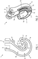
- In den
Fig. 1 und 2 ist das Bauteil lediglich beispielhaft als Haken dargestellt. - Das Bauteil 1 weist einen Lastaufnahmeabschnitt 2, an dem eine Last mittels eines Anschlagmittels (nicht gezeigt) angeschlagen und/oder eingehängt wird.
- Das Bauteil 1 weist ferner einen Anschlussabschnitt 3 auf, der zur Anbringung des Bauteils an einem weiteren Gegenstand dient.
- Das Bauteil 1 kann mehrere Lastaufnahmeabschnitte 2 sowie mehrere Anschlussabschnitte 3 aufweisen. Es kann beispielsweise als Haken einen weiteren Anschlussabschnitt 3' zur Anbringung einer Hakenfalle bzw. eines Verschlusses für das Hakenmaul aufweisen.
- Das Bauteil weist ein Kunststoff-Metall-Verbundsystem 4 auf. In diesem Verbundsystem sind wenigstens ein Kunststoff- und wenigstens ein Metallelement kombiniert und gemeinsam verarbeitet, um Eigenschaften zu erreichen, die die einzelnen Komponenten des Verbundsystems jeweils für sich betrachtet nicht haben.
- Das Kunststoff-Metall-Verbundsystem 4 weist einen Kern 5 auf, der teilweise die Außenfläche des Bauteils 1 bilden kann. Der Kern ist selbst aus einem Faser-Kunststoff-Verbund gefertigt und bildet eine Tragestruktur 6, welche eine auf den Lastaufnahmeabschnitt 2 wirkende Kraft 7 zum Anschlussabschnitt 3 leitet. Vom Anschlussabschnitt 3 wird sie in den dort angebrachten Gegenstand eingeleitet. Die Richtung des Kraftflusses kann sich auch verändern .
- Der Kern 5 bildet wenigstens bereichsweise eine Außenfläche 7 des Bauteils 1. Um den Kern 5 zu schützen, kann er außen mit einem stoßabsorbierenden Material beschichtet sein, das sich vom Material des Kerns unterscheidet. Diese Außenhülle (nicht gezeigt) kann Teil des Faser-Kunststoff-Verbunds sein. So kann beispielsweise der Kern außen mit einer elastischen gummiartigen Hülle wenigstens abschnittsweise umgeben sein, damit Stöße das Bauteil 1 bzw. den Kern 5 nicht beschädigen können. Die Verwendung des Bauteils 1 in bestimmten korrosiven Umgebungen kann es ferner notwendig machen, den Kern 5 mit einer Schutzschicht aus einem gegenüber dieser Umgebung korrosionsbeständigen Schicht zu überziehen. Eine solche Schicht kann Teil des Faser-Kunststoff-Verbunds sein.
- Das Kunststoff-Metall-Verbundsystem 4 weist ferner wenigstens eine Außenschale 8 auf, die sich wenigstens am Lastaufnahmeabschnitt 2 und/oder am Anschlussabschnitt 3 befindet und dort die Außenfläche 7 des Bauteils 1 bildet. Die Außenschale 8 ist aus einem Metallwerkstoff gefertigt.
- Der Lastaufnahmeabschnitt 2 und/oder der Anschlussabschnitt 3 können wenigstens einen zylindrischen Durchbruch 9 aufweisen, der von der Außenschale 8 zumindest abschnittsweise ausgekleidet ist.
- Die Außenschale 8 dient dazu, eine von außen auf das Bauteil 1 wirkende Kraft 7 aufzunehmen und über eine größere Fläche an den Kern 5 weiterzuleiten. Gleichzeitig soll die Außenschale 8 eine größere Verschleißfestigkeit gegen Stoß und Abrieb bewirken.
- Wenn, wie bei einem Haken, der Lastaufnahmeabschnitt 2 in etwa bügelförmig ausgestaltet ist, kann die Außenschale 8 wenigstens bereichsweise die Innenfläche 10 des Lastaufnahmeabschnittes bilden.
- Dabei kann sich die Außenschale 8 wenigstens abschnittsweise über die sich an die Innenfläche anschließenden Seitenflächen 11 des Bauteils 1 erstrecken. Um den Kern 5 an dieser Stelle besser zu schützen, kann dieser bezüglich der Außenschale 8 beispielsweise durch eine Kehlung etwas zurückspringen, so dass ein am Lastaufnahmeabschnitt 2 eingehängtes Anschlagmittel den Kern nicht berühren kann.
- An der Innenfläche 10 des Lastaufnahmeabschnittes 2 kann sich die Außenschale 8 in dessen Längsrichtung 12 über einen Bereich 13 erstrecken, der mehr als einen Halbkreisbogen, also über 180° einnimmt.
- In dem weggebrochen dargestellten Bereich 14 der
Fig. 2 , der den Blick auf das Innere des Kerns 5 freigibt, ist zu erkennen, dass im Kern 5 Elektronikkomponenten 15 eingebettet sein können. Diese Elektronikkomponenten können RFID-Elemente, Sensoren, Speicher und Ähnliches umfassen, um Betriebszustände des Sensors aufzuzeichnen und fernabfragen zu können. Außerdem können Kennungen, die das Bauteil und dessen Wartungszustand identifizieren, ebenfalls in den Elektronikkomponenten integriert sein. - Der Faser-Kunststoff-Verbund 16 des Kerns 5 weist bevorzugt Endlosfasern auf, die in
Fig. 2 lediglich anhand einer einzelnen Endlosfaser 17 schematisch dargestellt sind. Wenigstens ein Teil der Endlosfasern 17 umschlingt einen zylindrischen Durchbruch 9 des Bauteils 1, um die Tragfähigkeit zu erhöhen. - Wie die
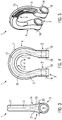
Fig. 3 bis 5 zeigen, kann das Bauteil 1, wie es oben beschrieben ist, auch als Schäkel ausgestaltet sein. Der Anschlussabschnitt 3 nimmt beim Schäkel den Schließbolzen (nicht gezeigt) als weiteren Gegenstand auf. Die zylindrischen Durchbrüche 9 sind mit jeweils einer separaten Außenschale 8 innen ausgekleidet, die zudem an den Stirnseiten der zylindrischen Durchbrüche 9 einen Flanschabschnitt 18 bilden, um Beschädigungen des Kerns 5 aufgrund großer Flächenpressung zu vermeiden. - In dem weggebrochen dargestellten Bereich 14 der
Fig. 3 ist zu erkennen, dass in dem Kern 5 auch wenigstens ein faserrichtungsweisendes Element 19 eingebettet sein kann. Das faserrichtungsweisende Element 19 befindet sich bevorzugt in einem Bereich 20, in dem die Materialstärke 21 des Kerns gegenüber angrenzenden Bereichen stark erhöht ist. In einem solchen verdickten Bereich 20 besteht bei der Fertigung des Faser-Kunststoff-Verbundes 16 bzw. des gesamten Kunststoff-Metall-Verbundsystems 4 die Gefahr, dass die Fließrichtung des Kunststoffes mit den Fasern unbestimmt ist. Dies kann zu einer Wirrlage der Fasern führen, durch die die Tragfähigkeit des Faser-Kunststoff-Verbundes nicht optimal ausgenutzt werden kann. Um bei der Fertigung die Faserrichtung 22 belastungsgerecht auszurichten, ist in wenigstens einem Bereich 20 mit erhöhter Materialstärke 21 das faserrichtungsweisende Element 19 angeordnet. Ein solcher Bereich 20 befindet sich beispielsweise an einem bzw. angrenzend an ein Loch 9. - Das faserrichtungsweisende Element 19 kann konus- oder keilförmig sein, wobei es sich von dem Bereich 20 mit der größeren Materialstärke 21 weg verjüngt. Die Basis eines solchen keilförmigen Elements 11 befindet sich bevorzugt an einem zylindrischen Durchbruch 9.
- Bei der Verwendung von Endlosfasern 17 können diese bei einem bügelförmigen Lastaufnahmeabschnitt 2 oder Anschlussabschnitt 3 schlaufenförmig um die beiden zylindrischen Durchbrüche 9 gelegt werden, wie dies in den
Fig. 3 und 4 angedeutet ist. - Das Bauteil 1 kann auch als Anschlagpunkt ausgestaltet sein, wie
Fig. 6 zeigt. Die Außenschale 8 kann sich im Bereich des Anschlussabschnitt 3 befinden, mit dem der Anschlagpunkt an einem Gegenstand, beispielsweise einer zu hebenden Last befestigt wird. In diesem Fall weist der Lastaufnahmeabschnitt 2 einen zylindrischen Durchbruch 9 in Form einer Öse auf, durch die ein Anschlagmittel (nicht gezeigt) zum Heben der Last gefädelt werden muss. Die Innenfläche 10 des Lastaufnahmeabschnittes ist ebenfalls mit einer Außenschale 8 versehen. - An der Außenfläche 11 des Lastaufnahmeabschnittes 2 kann sich eine weitere Außenschale 8 befinden, um eine Beschädigung des Kerns 5 bei Stößen zu verhindern.
- Die Außenschale 8 befindet sich zudem dort, wo mit Werkzeugen am Bauteil 1 hantiert wird, beispielsweise an einem einen Schraubenkopf 23 bildenden Abschnitt.
- Wie schließlich
Fig. 7 zeigt, kann das Bauteil 1 auch ein Ringglied sein, bei dem Lastaufnahmeabschnitt 2 und Anschlussabschnitt 3 identisch ausgestaltet sind. -
- 1
- lastaufnehmendes Bauteil der Anschlag-, Zurr- und/oder Hebetechnik
- 2
- Lastaufnahmeabschnitt
- 3
- Anschlussabschnitt
- 3'
- weiterer Anschlussabschnitt
- 4
- Kunststoff-Metall-Verbundsystem
- 5
- Kern
- 6
- Tragestruktur
- 7
- Außenfläche
- 8
- Außenschale
- 9
- Zylindrischer Durchbruch
- 10
- Innenfläche
- 11
- Seitenfläche
- 12
- Längsrichtung
- 13
- von Außenschale abgedeckter Bereich des Kerns
- 14
- weggebrochen dargestellter Bereich
- 15
- Elektronikkomponente
- 16
- Faser-Kunststoff-Verbund
- 17
- Endlosfaser
- 18
- Flanschabschnitt
- 19
- faserrichtungsweisendes Element
- 20
- Bereich mit erhöhter Materialstärke
- 21
- Materialstärke
- 22
- Faserrichtung
- 23
- Schraubenkopf
- K
- Kraft
Claims (15)
- Lastaufnehmendes Bauteil (1) der Anschlag-, Zurr- und/oder Hebetechnik zur Lastaufnahme, mit einem Kunststoff-Metall-Verbundsystem (4), das wenigstens einen Lastaufnahmeabschnitt (2) zum Anschlagen und/oder Einhängen einer Last und/oder eines Anschlagmittels und wenigstens einen Anschlussabschnitt (3) zur Anbringung eines Gegenstandes am Bauteil (1) ausbildet, dadurch gekennzeichnet, dass das Kunststoff-Metall-Verbundsystem (4) einen sich vom Lastaufnahmeabschnitt (2) zum Anschlussabschnitt (3) durchgängig erstreckenden, eine Tragestruktur (6) bildenden Kern (5) aus einem Faser-Kunststoff-Verbund (16) und wenigstens eine sich am Lastaufnahmeabschnitt (2) und/oder Anschlussabschnitt (3) befindliche Außenschale (8) aus einem Metallwerkstoff aufweist.
- Lastaufnehmendes Bauteil (1) nach Anspruch 1, dadurch gekennzeichnet, dass der Kern (5) an den nicht von der wenigstens einen Außenschale (8) abgedeckten Bereichen die Außenfläche (11) des Bauteils (1) bildet.
- Lastaufnehmendes Bauteil (1) nach Anspruch 1 oder 2, dadurch gekennzeichnet, dass im Kern (5) des Kunststoff-Metall-Verbundsystems (4) wenigstens ein faserrichtungsweisendes Element (19) eingebettet ist.
- Lastaufnehmendes Bauteil (1) nach Anspruch 3, dadurch gekennzeichnet, dass das faserrichtungsweisende Element (19) konus- oder keilförmig ausgestaltet ist.
- Lastaufnehmendes Bauteil (1) nach Anspruch 3 oder 4, dadurch gekennzeichnet, dass das faserrichtungsweisende Element (19) sich in einem Bereich (20) befindet, in dem die Materialstärke (21) des Faser-Kunststoff-Verbundes (16) gegenüber der Umgebung erhöht ist.
- Lastaufnehmendes Bauteil (1) nach einem der Ansprüche 3 bis 5, dadurch gekennzeichnet, dass das faserrichtungsweisende Element (19) sich an einem Loch (9) des Bauteils (1) befindet.
- Lastaufnehmendes Bauteil nach Anspruch 6, dadurch gekennzeichnet, dass das faserrichtungsweisende Element (19) sich vom Loch weg verjüngt.
- Lastaufnehmendes Bauteil (1) nach einem der Ansprüche 1 bis 7, dadurch gekennzeichnet, dass die Außenschale (8) einen zylindrischen Durchbruch (9) des Bauteils (1) wenigstens abschnittsweise auskleidet.
- Lastaufnehmendes Bauteil (1) nach einem der Ansprüche 1 bis 8, dadurch gekennzeichnet, dass im Kern (5) wenigstens eine Elektronikkomponente (15) eingebettet ist.
- Lastaufnehmendes Bauteil (1) nach einem der Ansprüche 1 bis 9, dadurch gekennzeichnet, dass der Lastaufnahmeabschnitt (2) bügelförmig ausgestaltet ist und eine Innenfläche (10) des Lastaufnahmeabschnittes (2) von der Außenschale (8) gebildet ist.
- Lastaufnehmendes Bauteil (1) nach Anspruch 10, dadurch gekennzeichnet, dass sich die Außenschale (8) wenigstens abschnittsweise über die sich an die Innenfläche (10) anschließenden Seitenflächen (11) des Lastaufnahmeabschnitt (2) erstreckt.
- Lastaufnehmendes Bauteil (1) nach Anspruch 10 oder 11, dadurch gekennzeichnet, dass sich die Außenschale (8) in Längsrichtung (12) des Lastaufnahmeabschnittes (2) um mehr als 180° erstreckt.
- Lastaufnehmendes Bauteil (1) nach einem der Ansprüche 1 bis 12, dadurch gekennzeichnet, dass die wenigstens eine Außenschale (8) an einem zylindrischen Durchbruch (9) eine Flanschfläche (18) bildet.
- Lastaufnehmendes Bauteil (1) nach einem der Ansprüche 1 bis 13, dadurch gekennzeichnet, dass der Faser-Kunststoff-Verbund (16) Endlosfasern (17) aufweist.
- Lastaufnehmendes Bauteil (1) nach Anspruch 14, dadurch gekennzeichnet, dass wenigstens einige der Endlosfasern (17) wenigstens einen zylindrischen Durchbruch (9) des Bauteils (1) umschlingen.
Applications Claiming Priority (1)
| Application Number | Priority Date | Filing Date | Title |
|---|---|---|---|
| DE102016202782.4A DE102016202782A1 (de) | 2016-02-23 | 2016-02-23 | Lastaufnehmendes Bauteil der Anschlag-, Zurr- und/oder Hebetechnik mit einem Kunststoff-Metall-Verbundsystem |
Publications (2)
| Publication Number | Publication Date |
|---|---|
| EP3210929A1 true EP3210929A1 (de) | 2017-08-30 |
| EP3210929B1 EP3210929B1 (de) | 2022-11-23 |
Family
ID=58098482
Family Applications (1)
| Application Number | Title | Priority Date | Filing Date |
|---|---|---|---|
| EP17156523.7A Active EP3210929B1 (de) | 2016-02-23 | 2017-02-16 | Lastaufnehmendes bauteil der anschlag-, zurr- und/oder hebetechnik mit einem kunststoff-metall-verbundsystem |
Country Status (5)
| Country | Link |
|---|---|
| US (1) | US10072698B2 (de) |
| EP (1) | EP3210929B1 (de) |
| CN (1) | CN107098263B (de) |
| DE (1) | DE102016202782A1 (de) |
| ES (1) | ES2937786T3 (de) |
Families Citing this family (8)
| Publication number | Priority date | Publication date | Assignee | Title |
|---|---|---|---|---|
| GB2537938B (en) * | 2015-05-01 | 2019-07-10 | Treemagineers Ltd | Throwing hook |
| NL2018463B1 (en) * | 2017-03-02 | 2018-09-21 | Rotortug Holding B V | Smartlink |
| USD849518S1 (en) * | 2018-03-30 | 2019-05-28 | Joanne Crawford | Chain hook |
| USD849517S1 (en) * | 2018-03-30 | 2019-05-28 | Joanne Crawford | Chain hook |
| NL2021139B1 (en) | 2018-06-18 | 2020-01-06 | High Performance Lifting Equipment B V | Lifting tool |
| US10604058B1 (en) | 2018-11-26 | 2020-03-31 | Bnsf Logistics, Llc | Lashing pawl |
| US10717630B1 (en) * | 2019-02-12 | 2020-07-21 | Chant Engineering Co. Inc. | Light weight load bearing shackle with fiber rope bow |
| US11370641B2 (en) * | 2019-02-12 | 2022-06-28 | Chant Engineering Co. Inc. | Lightweight and flexible load bearing shackle utilizing a plurality of loops of fiber rope as a bow |
Citations (6)
| Publication number | Priority date | Publication date | Assignee | Title |
|---|---|---|---|---|
| DE1258056B (de) * | 1963-10-04 | 1968-01-04 | Intercontinentale Technik Ges | Lasthaken |
| WO2004106772A2 (en) * | 2003-05-28 | 2004-12-09 | Top Glass S.P.A. | Junction system and procedure for joining a filiform element to a connection element |
| EP2039959A1 (de) * | 2007-09-19 | 2009-03-25 | de Vries, Oscar | Kettenglied |
| DE102008013203A1 (de) * | 2008-03-08 | 2009-09-17 | Terex-Demag Gmbh | Ausleger zur endseitigen Aufnahme von Lasten, Ausleger-Baugruppe mit mindestens zwei derartigen Auslegern sowie Verfahren zur Herstellung eines derartigen Auslegers |
| DE202014104023U1 (de) | 2014-08-28 | 2014-09-09 | Thiele Gmbh & Co. Kg | Hybridhaken |
| DE102014200153A1 (de) * | 2014-01-08 | 2015-07-09 | Rud Ketten Rieger & Dietz Gmbh U. Co. Kg | Zugstange aus faserverstärktem Kunststoff mit um wenigstens einen Flanschkörper herum reichenden Fasern |
Family Cites Families (11)
| Publication number | Priority date | Publication date | Assignee | Title |
|---|---|---|---|---|
| US2709616A (en) * | 1952-09-15 | 1955-05-31 | Larson Victor Sjunne | Thimble ring for shackles |
| US3056167A (en) * | 1958-07-16 | 1962-10-02 | Proman Inc | Mold for high strength members |
| US4561272A (en) * | 1984-07-05 | 1985-12-31 | The United States Of America As Represented By The Secretary Of The Navy | Padlock shackle |
| ATE150712T1 (de) | 1993-10-06 | 1997-04-15 | Abb Daimler Benz Transp | Verbundbauteil als zug-druck-stange für schienenfahrzeuge |
| IT1313171B1 (it) * | 1999-08-06 | 2002-06-17 | Kong Spa | Grillo maniglia per aggancio su catena |
| EP2006474A1 (de) * | 2004-09-28 | 2008-12-24 | E-Lock Technologies Limited | Behälterschloss und -versiegelung |
| CN103299185A (zh) | 2011-01-11 | 2013-09-11 | 西门子公司 | 用于确定具有分布于层压材料中的多个纤维的纤维强化部件中的纤维取向的方法 |
| WO2012134699A1 (en) * | 2011-04-01 | 2012-10-04 | Tough Gear Inc. | Paracord bracelet with shackle connector |
| CA2920514C (en) * | 2014-01-13 | 2017-03-21 | Slingmax, Inc. | Roundslings with radio frequency identification pre-failure warning indicators |
| US9861839B2 (en) * | 2014-02-19 | 2018-01-09 | D B Industries, Llc | Connector |
| US9856905B2 (en) * | 2014-05-27 | 2018-01-02 | David Soderberg Servais | Shackle with low-force release system |
-
2016
- 2016-02-23 DE DE102016202782.4A patent/DE102016202782A1/de active Pending
-
2017
- 2017-02-16 EP EP17156523.7A patent/EP3210929B1/de active Active
- 2017-02-16 ES ES17156523T patent/ES2937786T3/es active Active
- 2017-02-21 US US15/438,352 patent/US10072698B2/en active Active
- 2017-02-23 CN CN201710099076.8A patent/CN107098263B/zh active Active
Patent Citations (6)
| Publication number | Priority date | Publication date | Assignee | Title |
|---|---|---|---|---|
| DE1258056B (de) * | 1963-10-04 | 1968-01-04 | Intercontinentale Technik Ges | Lasthaken |
| WO2004106772A2 (en) * | 2003-05-28 | 2004-12-09 | Top Glass S.P.A. | Junction system and procedure for joining a filiform element to a connection element |
| EP2039959A1 (de) * | 2007-09-19 | 2009-03-25 | de Vries, Oscar | Kettenglied |
| DE102008013203A1 (de) * | 2008-03-08 | 2009-09-17 | Terex-Demag Gmbh | Ausleger zur endseitigen Aufnahme von Lasten, Ausleger-Baugruppe mit mindestens zwei derartigen Auslegern sowie Verfahren zur Herstellung eines derartigen Auslegers |
| DE102014200153A1 (de) * | 2014-01-08 | 2015-07-09 | Rud Ketten Rieger & Dietz Gmbh U. Co. Kg | Zugstange aus faserverstärktem Kunststoff mit um wenigstens einen Flanschkörper herum reichenden Fasern |
| DE202014104023U1 (de) | 2014-08-28 | 2014-09-09 | Thiele Gmbh & Co. Kg | Hybridhaken |
Also Published As
| Publication number | Publication date |
|---|---|
| CN107098263A (zh) | 2017-08-29 |
| ES2937786T3 (es) | 2023-03-31 |
| US20170241469A1 (en) | 2017-08-24 |
| DE102016202782A1 (de) | 2017-08-24 |
| CN107098263B (zh) | 2019-06-28 |
| EP3210929B1 (de) | 2022-11-23 |
| US10072698B2 (en) | 2018-09-11 |
Similar Documents
| Publication | Publication Date | Title |
|---|---|---|
| EP3210929B1 (de) | Lastaufnehmendes bauteil der anschlag-, zurr- und/oder hebetechnik mit einem kunststoff-metall-verbundsystem | |
| EP3038944B1 (de) | Vorrichtung zur datenübertragung unter einsatz eines transponders | |
| EP2388227B1 (de) | Kranhaken mit einer Hakengewichtsanordnung | |
| DE102004020039B3 (de) | Tragbolzen | |
| EP2607290B1 (de) | Wippe für Gehänge mit Anzeigeanordnung | |
| DE112016003896T5 (de) | Baumaschine mit Kunststoffseilanordnung | |
| DE102017219739A1 (de) | Heb- und senkbare Lastaufnahmemittel mit einer Kabelführung in teleskopierbaren Gabelzinken | |
| DE10036014A1 (de) | Sicherheitsbauteil aus Stahl für die Hebe-, Zurr-, Förder- und Gewinnungstechnik | |
| WO2016029899A1 (de) | Hybridhaken | |
| DE10100993A1 (de) | Einrichtung zum Verstellen einer Länge eines als Endlosschlinge ausgebildeten Anschlagmittels und Vorrichtung zum Heben von Lasten | |
| EP3140237B1 (de) | Ringelement mit einem geteilten sockel für ein zurr- oder anschlagmittel | |
| EP1791777B1 (de) | Schutzelement für textile zurr- oder anschlagmittel und mit einem solchen schutzelement ausgestattetes zurr- oder anschlagmittel | |
| DE102014208822A1 (de) | Anschlagpunkt mit einer Textilschlinge | |
| EP2580490B1 (de) | Seilendverbindung | |
| DE202007003887U1 (de) | Gewebter Schutzschlauch | |
| DE102012107733A1 (de) | Anschlagpunkt | |
| EP4132874B1 (de) | Transporthaken | |
| EP3070369B1 (de) | Seilgleitring, insbesondere chokerring | |
| WO2007033986A1 (de) | Lastaufnahmehaken mit einem fachwerk | |
| DE102014200153B4 (de) | Zugstange aus faserverstärktem Kunststoff mit um wenigstens einen Flanschkörper herum reichenden Fasern | |
| DE202018107005U1 (de) | Kettengehänge zum Aufhängen einer Last an einem Kranhaken | |
| DE7041555U (de) | Kettenstrang | |
| DE20313636U1 (de) | Schutzschlauch mit integrierter Fangkette | |
| DE202023105734U1 (de) | Vorrichtung zur Anbringung an einer textilen Kette | |
| DE202015008100U1 (de) | Spannsystem zum Aufspannen und Befestigen eines Balancierbandes |
Legal Events
| Date | Code | Title | Description |
|---|---|---|---|
| PUAI | Public reference made under article 153(3) epc to a published international application that has entered the european phase |
Free format text: ORIGINAL CODE: 0009012 |
|
| STAA | Information on the status of an ep patent application or granted ep patent |
Free format text: STATUS: THE APPLICATION HAS BEEN PUBLISHED |
|
| AK | Designated contracting states |
Kind code of ref document: A1 Designated state(s): AL AT BE BG CH CY CZ DE DK EE ES FI FR GB GR HR HU IE IS IT LI LT LU LV MC MK MT NL NO PL PT RO RS SE SI SK SM TR |
|
| AX | Request for extension of the european patent |
Extension state: BA ME |
|
| STAA | Information on the status of an ep patent application or granted ep patent |
Free format text: STATUS: REQUEST FOR EXAMINATION WAS MADE |
|
| 17P | Request for examination filed |
Effective date: 20180228 |
|
| RBV | Designated contracting states (corrected) |
Designated state(s): AL AT BE BG CH CY CZ DE DK EE ES FI FR GB GR HR HU IE IS IT LI LT LU LV MC MK MT NL NO PL PT RO RS SE SI SK SM TR |
|
| STAA | Information on the status of an ep patent application or granted ep patent |
Free format text: STATUS: EXAMINATION IS IN PROGRESS |
|
| 17Q | First examination report despatched |
Effective date: 20200716 |
|
| GRAJ | Information related to disapproval of communication of intention to grant by the applicant or resumption of examination proceedings by the epo deleted |
Free format text: ORIGINAL CODE: EPIDOSDIGR1 |
|
| GRAC | Information related to communication of intention to grant a patent modified |
Free format text: ORIGINAL CODE: EPIDOSCIGR1 |
|
| GRAP | Despatch of communication of intention to grant a patent |
Free format text: ORIGINAL CODE: EPIDOSNIGR1 |
|
| STAA | Information on the status of an ep patent application or granted ep patent |
Free format text: STATUS: GRANT OF PATENT IS INTENDED |
|
| INTG | Intention to grant announced |
Effective date: 20220707 |
|
| INTG | Intention to grant announced |
Effective date: 20220711 |
|
| INTG | Intention to grant announced |
Effective date: 20220707 |
|
| GRAS | Grant fee paid |
Free format text: ORIGINAL CODE: EPIDOSNIGR3 |
|
| GRAA | (expected) grant |
Free format text: ORIGINAL CODE: 0009210 |
|
| STAA | Information on the status of an ep patent application or granted ep patent |
Free format text: STATUS: THE PATENT HAS BEEN GRANTED |
|
| AK | Designated contracting states |
Kind code of ref document: B1 Designated state(s): AL AT BE BG CH CY CZ DE DK EE ES FI FR GB GR HR HU IE IS IT LI LT LU LV MC MK MT NL NO PL PT RO RS SE SI SK SM TR |
|
| REG | Reference to a national code |
Ref country code: GB Ref legal event code: FG4D Free format text: NOT ENGLISH |
|
| REG | Reference to a national code |
Ref country code: CH Ref legal event code: EP |
|
| REG | Reference to a national code |
Ref country code: DE Ref legal event code: R096 Ref document number: 502017014114 Country of ref document: DE |
|
| REG | Reference to a national code |
Ref country code: AT Ref legal event code: REF Ref document number: 1533049 Country of ref document: AT Kind code of ref document: T Effective date: 20221215 |
|
| REG | Reference to a national code |
Ref country code: IE Ref legal event code: FG4D Free format text: LANGUAGE OF EP DOCUMENT: GERMAN |
|
| REG | Reference to a national code |
Ref country code: NL Ref legal event code: FP |
|
| REG | Reference to a national code |
Ref country code: LT Ref legal event code: MG9D |
|
| REG | Reference to a national code |
Ref country code: SE Ref legal event code: TRGR |
|
| REG | Reference to a national code |
Ref country code: ES Ref legal event code: FG2A Ref document number: 2937786 Country of ref document: ES Kind code of ref document: T3 Effective date: 20230331 |
|
| PG25 | Lapsed in a contracting state [announced via postgrant information from national office to epo] |
Ref country code: PT Free format text: LAPSE BECAUSE OF FAILURE TO SUBMIT A TRANSLATION OF THE DESCRIPTION OR TO PAY THE FEE WITHIN THE PRESCRIBED TIME-LIMIT Effective date: 20230323 Ref country code: NO Free format text: LAPSE BECAUSE OF FAILURE TO SUBMIT A TRANSLATION OF THE DESCRIPTION OR TO PAY THE FEE WITHIN THE PRESCRIBED TIME-LIMIT Effective date: 20230223 Ref country code: LT Free format text: LAPSE BECAUSE OF FAILURE TO SUBMIT A TRANSLATION OF THE DESCRIPTION OR TO PAY THE FEE WITHIN THE PRESCRIBED TIME-LIMIT Effective date: 20221123 Ref country code: FI Free format text: LAPSE BECAUSE OF FAILURE TO SUBMIT A TRANSLATION OF THE DESCRIPTION OR TO PAY THE FEE WITHIN THE PRESCRIBED TIME-LIMIT Effective date: 20221123 |
|
| PG25 | Lapsed in a contracting state [announced via postgrant information from national office to epo] |
Ref country code: RS Free format text: LAPSE BECAUSE OF FAILURE TO SUBMIT A TRANSLATION OF THE DESCRIPTION OR TO PAY THE FEE WITHIN THE PRESCRIBED TIME-LIMIT Effective date: 20221123 Ref country code: PL Free format text: LAPSE BECAUSE OF FAILURE TO SUBMIT A TRANSLATION OF THE DESCRIPTION OR TO PAY THE FEE WITHIN THE PRESCRIBED TIME-LIMIT Effective date: 20221123 Ref country code: LV Free format text: LAPSE BECAUSE OF FAILURE TO SUBMIT A TRANSLATION OF THE DESCRIPTION OR TO PAY THE FEE WITHIN THE PRESCRIBED TIME-LIMIT Effective date: 20221123 Ref country code: IS Free format text: LAPSE BECAUSE OF FAILURE TO SUBMIT A TRANSLATION OF THE DESCRIPTION OR TO PAY THE FEE WITHIN THE PRESCRIBED TIME-LIMIT Effective date: 20230323 Ref country code: HR Free format text: LAPSE BECAUSE OF FAILURE TO SUBMIT A TRANSLATION OF THE DESCRIPTION OR TO PAY THE FEE WITHIN THE PRESCRIBED TIME-LIMIT Effective date: 20221123 Ref country code: GR Free format text: LAPSE BECAUSE OF FAILURE TO SUBMIT A TRANSLATION OF THE DESCRIPTION OR TO PAY THE FEE WITHIN THE PRESCRIBED TIME-LIMIT Effective date: 20230224 |
|
| PG25 | Lapsed in a contracting state [announced via postgrant information from national office to epo] |
Ref country code: SM Free format text: LAPSE BECAUSE OF FAILURE TO SUBMIT A TRANSLATION OF THE DESCRIPTION OR TO PAY THE FEE WITHIN THE PRESCRIBED TIME-LIMIT Effective date: 20221123 Ref country code: RO Free format text: LAPSE BECAUSE OF FAILURE TO SUBMIT A TRANSLATION OF THE DESCRIPTION OR TO PAY THE FEE WITHIN THE PRESCRIBED TIME-LIMIT Effective date: 20221123 Ref country code: EE Free format text: LAPSE BECAUSE OF FAILURE TO SUBMIT A TRANSLATION OF THE DESCRIPTION OR TO PAY THE FEE WITHIN THE PRESCRIBED TIME-LIMIT Effective date: 20221123 Ref country code: DK Free format text: LAPSE BECAUSE OF FAILURE TO SUBMIT A TRANSLATION OF THE DESCRIPTION OR TO PAY THE FEE WITHIN THE PRESCRIBED TIME-LIMIT Effective date: 20221123 Ref country code: CZ Free format text: LAPSE BECAUSE OF FAILURE TO SUBMIT A TRANSLATION OF THE DESCRIPTION OR TO PAY THE FEE WITHIN THE PRESCRIBED TIME-LIMIT Effective date: 20221123 |
|
| REG | Reference to a national code |
Ref country code: DE Ref legal event code: R097 Ref document number: 502017014114 Country of ref document: DE |
|
| PG25 | Lapsed in a contracting state [announced via postgrant information from national office to epo] |
Ref country code: SK Free format text: LAPSE BECAUSE OF FAILURE TO SUBMIT A TRANSLATION OF THE DESCRIPTION OR TO PAY THE FEE WITHIN THE PRESCRIBED TIME-LIMIT Effective date: 20221123 Ref country code: AL Free format text: LAPSE BECAUSE OF FAILURE TO SUBMIT A TRANSLATION OF THE DESCRIPTION OR TO PAY THE FEE WITHIN THE PRESCRIBED TIME-LIMIT Effective date: 20221123 |
|
| REG | Reference to a national code |
Ref country code: DE Ref legal event code: R119 Ref document number: 502017014114 Country of ref document: DE |
|
| PG25 | Lapsed in a contracting state [announced via postgrant information from national office to epo] |
Ref country code: MC Free format text: LAPSE BECAUSE OF FAILURE TO SUBMIT A TRANSLATION OF THE DESCRIPTION OR TO PAY THE FEE WITHIN THE PRESCRIBED TIME-LIMIT Effective date: 20221123 |
|
| PLBE | No opposition filed within time limit |
Free format text: ORIGINAL CODE: 0009261 |
|
| REG | Reference to a national code |
Ref country code: CH Ref legal event code: PL |
|
| STAA | Information on the status of an ep patent application or granted ep patent |
Free format text: STATUS: NO OPPOSITION FILED WITHIN TIME LIMIT |
|
| REG | Reference to a national code |
Ref country code: BE Ref legal event code: MM Effective date: 20230228 |
|
| PG25 | Lapsed in a contracting state [announced via postgrant information from national office to epo] |
Ref country code: LI Free format text: LAPSE BECAUSE OF NON-PAYMENT OF DUE FEES Effective date: 20230228 Ref country code: CH Free format text: LAPSE BECAUSE OF NON-PAYMENT OF DUE FEES Effective date: 20230228 |
|
| 26N | No opposition filed |
Effective date: 20230824 |
|
| PG25 | Lapsed in a contracting state [announced via postgrant information from national office to epo] |
Ref country code: SI Free format text: LAPSE BECAUSE OF FAILURE TO SUBMIT A TRANSLATION OF THE DESCRIPTION OR TO PAY THE FEE WITHIN THE PRESCRIBED TIME-LIMIT Effective date: 20221123 |
|
| REG | Reference to a national code |
Ref country code: IE Ref legal event code: MM4A |
|
| PG25 | Lapsed in a contracting state [announced via postgrant information from national office to epo] |
Ref country code: IE Free format text: LAPSE BECAUSE OF NON-PAYMENT OF DUE FEES Effective date: 20230216 Ref country code: DE Free format text: LAPSE BECAUSE OF NON-PAYMENT OF DUE FEES Effective date: 20230901 |
|
| PG25 | Lapsed in a contracting state [announced via postgrant information from national office to epo] |
Ref country code: BE Free format text: LAPSE BECAUSE OF NON-PAYMENT OF DUE FEES Effective date: 20230228 |
|
| PG25 | Lapsed in a contracting state [announced via postgrant information from national office to epo] |
Ref country code: BG Free format text: LAPSE BECAUSE OF FAILURE TO SUBMIT A TRANSLATION OF THE DESCRIPTION OR TO PAY THE FEE WITHIN THE PRESCRIBED TIME-LIMIT Effective date: 20221123 |
|
| PG25 | Lapsed in a contracting state [announced via postgrant information from national office to epo] |
Ref country code: BG Free format text: LAPSE BECAUSE OF FAILURE TO SUBMIT A TRANSLATION OF THE DESCRIPTION OR TO PAY THE FEE WITHIN THE PRESCRIBED TIME-LIMIT Effective date: 20221123 |
|
| PG25 | Lapsed in a contracting state [announced via postgrant information from national office to epo] |
Ref country code: CY Free format text: LAPSE BECAUSE OF FAILURE TO SUBMIT A TRANSLATION OF THE DESCRIPTION OR TO PAY THE FEE WITHIN THE PRESCRIBED TIME-LIMIT; INVALID AB INITIO Effective date: 20170216 |
|
| PG25 | Lapsed in a contracting state [announced via postgrant information from national office to epo] |
Ref country code: HU Free format text: LAPSE BECAUSE OF FAILURE TO SUBMIT A TRANSLATION OF THE DESCRIPTION OR TO PAY THE FEE WITHIN THE PRESCRIBED TIME-LIMIT; INVALID AB INITIO Effective date: 20170216 |
|
| PG25 | Lapsed in a contracting state [announced via postgrant information from national office to epo] |
Ref country code: TR Free format text: LAPSE BECAUSE OF FAILURE TO SUBMIT A TRANSLATION OF THE DESCRIPTION OR TO PAY THE FEE WITHIN THE PRESCRIBED TIME-LIMIT Effective date: 20221123 |
|
| PGFP | Annual fee paid to national office [announced via postgrant information from national office to epo] |
Ref country code: LU Payment date: 20260220 Year of fee payment: 10 Ref country code: NL Payment date: 20260228 Year of fee payment: 10 |
|
| PGFP | Annual fee paid to national office [announced via postgrant information from national office to epo] |
Ref country code: SE Payment date: 20260228 Year of fee payment: 10 |
|
| PGFP | Annual fee paid to national office [announced via postgrant information from national office to epo] |
Ref country code: GB Payment date: 20260226 Year of fee payment: 10 |
|
| PGFP | Annual fee paid to national office [announced via postgrant information from national office to epo] |
Ref country code: ES Payment date: 20260302 Year of fee payment: 10 |
|
| PGFP | Annual fee paid to national office [announced via postgrant information from national office to epo] |
Ref country code: AT Payment date: 20260223 Year of fee payment: 10 |
|
| PGFP | Annual fee paid to national office [announced via postgrant information from national office to epo] |
Ref country code: IT Payment date: 20260227 Year of fee payment: 10 |
|
| PGFP | Annual fee paid to national office [announced via postgrant information from national office to epo] |
Ref country code: FR Payment date: 20260225 Year of fee payment: 10 |