EP4132874B1 - Transporthaken - Google Patents
Transporthaken Download PDFInfo
- Publication number
- EP4132874B1 EP4132874B1 EP21716397.1A EP21716397A EP4132874B1 EP 4132874 B1 EP4132874 B1 EP 4132874B1 EP 21716397 A EP21716397 A EP 21716397A EP 4132874 B1 EP4132874 B1 EP 4132874B1
- Authority
- EP
- European Patent Office
- Prior art keywords
- hook
- transport
- section
- securing
- hole
- Prior art date
- Legal status (The legal status is an assumption and is not a legal conclusion. Google has not performed a legal analysis and makes no representation as to the accuracy of the status listed.)
- Active
Links
Images


Classifications
-
- B—PERFORMING OPERATIONS; TRANSPORTING
- B66—HOISTING; LIFTING; HAULING
- B66C—CRANES; LOAD-ENGAGING ELEMENTS OR DEVICES FOR CRANES, CAPSTANS, WINCHES, OR TACKLES
- B66C1/00—Load-engaging elements or devices attached to lifting or lowering gear of cranes or adapted for connection therewith for transmitting lifting forces to articles or groups of articles
- B66C1/10—Load-engaging elements or devices attached to lifting or lowering gear of cranes or adapted for connection therewith for transmitting lifting forces to articles or groups of articles by mechanical means
- B66C1/12—Slings comprising chains, wires, ropes, or bands; Nets
- B66C1/14—Slings with hooks
-
- B—PERFORMING OPERATIONS; TRANSPORTING
- B66—HOISTING; LIFTING; HAULING
- B66C—CRANES; LOAD-ENGAGING ELEMENTS OR DEVICES FOR CRANES, CAPSTANS, WINCHES, OR TACKLES
- B66C1/00—Load-engaging elements or devices attached to lifting or lowering gear of cranes or adapted for connection therewith for transmitting lifting forces to articles or groups of articles
- B66C1/10—Load-engaging elements or devices attached to lifting or lowering gear of cranes or adapted for connection therewith for transmitting lifting forces to articles or groups of articles by mechanical means
- B66C1/22—Rigid members, e.g. L-shaped members, with parts engaging the under surface of the loads; Crane hooks
- B66C1/34—Crane hooks
- B66C1/36—Crane hooks with means, e.g. spring-biased detents, for preventing inadvertent disengagement of loads
-
- B—PERFORMING OPERATIONS; TRANSPORTING
- B66—HOISTING; LIFTING; HAULING
- B66C—CRANES; LOAD-ENGAGING ELEMENTS OR DEVICES FOR CRANES, CAPSTANS, WINCHES, OR TACKLES
- B66C1/00—Load-engaging elements or devices attached to lifting or lowering gear of cranes or adapted for connection therewith for transmitting lifting forces to articles or groups of articles
- B66C1/10—Load-engaging elements or devices attached to lifting or lowering gear of cranes or adapted for connection therewith for transmitting lifting forces to articles or groups of articles by mechanical means
- B66C1/62—Load-engaging elements or devices attached to lifting or lowering gear of cranes or adapted for connection therewith for transmitting lifting forces to articles or groups of articles by mechanical means comprising article-engaging members of a shape complementary to that of the articles to be handled
- B66C1/66—Load-engaging elements or devices attached to lifting or lowering gear of cranes or adapted for connection therewith for transmitting lifting forces to articles or groups of articles by mechanical means comprising article-engaging members of a shape complementary to that of the articles to be handled for engaging holes, recesses, or abutments on articles specially provided for facilitating handling thereof
Definitions
- the invention relates to a transport hook for lifting and moving a load, such as floor elements that are placed close together and are only accessible from above.
- a flooring support structure comprising a plurality of longitudinally aligned boards that are fastened to one another.
- the flooring support structure has at least two coupling openings in the form of elongated holes that run parallel to one another at a predetermined distance.
- the double hook can engage laterally in the flooring support structure.
- a double hook can engage through the holes into the interior of the flooring support structure, and the double hook can be connected to a lifting device.
- the US 9,741,847 B2 discloses an industrial mat having a support structure and two holes.
- the holes can be used to support the industrial mat.
- Other known tools for lifting plate-shaped elements include, for example, channel hooks or pliers-like tools for gripping the plate-shaped element on the outer sides.
- the US 845,724 discloses a pin-shaped element attached to a base for insertion into a drilled hole in a stone block.
- the stone block can be lifted by frictional engagement in the drilled hole.
- the base protrudes laterally over the pin and rests against the surface of the stone block. This creates a wedging effect.
- a self-clamping lifting device for lifting stone blocks comprises a pin-shaped body to which a leg is connected at a right angle.
- a clamping lever is pivotally attached to the leg.
- a coupling element for attaching a rope is provided at one end of the clamping lever.
- the other end of the clamping lever has an edge that is pressed against the surface of a stone block when the pin-shaped section is inserted into a corresponding hole in the stone block.
- the US R E28 709 E relates to a lifting hook adapted to receive an end loop of a suspension rope, and a safety flap pivotally mounted on the lifting hook and shaped to hold the end loop of the suspension rope on the hook.
- a hook according to the preamble of claim 1 comprising an eyelet, a hook element, and a securing element.
- the eyelet is designed to receive a carrying rope or a carabiner.
- the hook element is designed to engage behind a hole in a load, and the securing element is designed to fix the hook in the hole.
- the JP H01 132686 U shows a hook with a particularly wide opening and a pivoting flap to further increase the gripping circumference of the hook, so that relatively large objects can be gripped with the hook.
- a hook is described that can engage a hole in a metal plate to lift it.
- the hook has a narrow opening, and the hole is characterized by its elliptical shape.
- the FR 2 677 969 A1 has a device for suspending a load to be handled. At least three hooks are provided, each of which engages a hole at one of the ends of the load and engages behind a projection on the hole. The hooks are each connected via a rope to a ring, which is lifted.
- a lifting hook is shown which is equipped with a locking pawl.
- the pawl is connected to a pulling element so that the pawl automatically closes an opening in the lifting hook as soon as, for example, a rope has been inserted into the opening.
- the object of the invention is to provide a transport hook and a lifting system with which a load can be securely gripped, lifted, and safely moved within a space.
- a further object is to provide a suitable method.
- the Figure 1 shows a transport hook 1 with which a load 101, for example a floor element of an event tent, can be lifted.
- a load 101 for example a floor element of an event tent
- the transport hook 1 comprises a lever section 2, a hook leg 3 and a retaining tab 6 which is connected to a securing device 7 with which the transport hook 1 can be secured in engagement with and in a partial penetration through a hole 102 of the load 101.
- the lever section 2 has a free end 2a and a coupling opening 4 acting as a coupling element, near a free end 2a remote from the hook shank 3.
- An angled section 14 adjoins the hook shank 3 and connects the hook shank and the lever section 2. The angled section is bent so that the lever section 2 and the hook shank 3 are arranged at an angle to each other.
- the lever section 2 has an engagement region 15 adjacent to the angle section 14, which has substantially the same cross-sectional shape as the angle section 14 and the hook leg 3 in order to engage, as explained in more detail below, in certain situations into a hole 102 of a load 101.
- the engagement region 15, the angled section 14, and the hook leg 3 have an approximately circular cross-section, which has slightly flattened surfaces 16 on the sides.
- the cross-section is formed substantially edge-free, so that it can rotate freely in a hole 102 about a hole axis 105, which runs centrally through the hole 102 and is perpendicular to a plate-shaped section of the load in which the hole 102 is made.
- substantially edge-free means that at edges only an obtuse angle of, for example, more than 100° and in particular more than 150° is formed. With such edges, the risk of hooking with projections formed on the hole edge is low.
- the flattened surfaces 16 in the Fig. 1 In the embodiment shown, the surfaces are approximately circular in cross-section and each have edges 17 which enclose an obtuse angle such that there is no danger of entanglement.
- the hook leg 3 is formed from an engagement portion 3a and a free end 3b remote from the angle portion, which has a blunt shape, for example in the form of a spherical segment.
- the transport hook 1 is formed in one piece or is molded from a single piece. This means that the transport hook 1 was, for example, cut from a sheet material, manufactured using a casting process, pressed from powder, or forged from a semi-finished product.
- the securing device 7 comprises a fastening plate 7a and a securing part, which in the present embodiment is formed from a hollow cylinder 7b and a securing rod 7c with a free end 7d.
- the securing part further comprises a handle 9 connected to the securing rod 7c.
- the hollow cylinder 7b has an internal thread, and the rear region of the securing rod 7c has an external thread, which engage with each other.
- a lock nut 7e fixes the disc-shaped handle 9 to the securing part, and the relative position of the securing rod 7c to the hollow cylinder 7b can be adjusted. This allows the length of the securing part to be adjusted and adapted to the size of the hole 102 of a load 101 to be lifted with the transport hook 1.
- the hollow cylinder 7b is slidably mounted in a through-bore 10 of the retaining tab 6.
- a compression spring (not shown) is arranged in the through-bore 10, which is supported on the mounting plate 7a and applies a force to the securing part 7b, 7c, 7e, which pushes the securing part away from the retaining tab 6.
- the safety rod 7c is slidably mounted in a through-hole 8 which extends through the angle section 14 and is fixed to the retaining tab 6 at the Side on the hook shank 3, so that the safety rod protrudes in a securing position with its free end 7d on the hook shank 3 ( Fig. 1 ).
- the through holes 8, 10 are aligned with each other, i.e. a central axis A10 of the hole 10 coincides with a central axis A8 of the hole 8.
- the handle 9 also serves as a stop to limit the movement of the securing part 7b, 7c, 7e between the securing position and a release position.
- the locking pin 7c protrudes from the hook shank 3 with its free end 7d, and the handle 9 abuts the lever section 2 at the engagement area 15.
- the release position the locking pin 7c is fully retracted with its free end 7d into the through-hole 8 of the transport hook 1, and the handle 9 abuts the retaining tab 6.
- the locking part can thus telescope out and in with respect to the through-hole 10.
- the securing rod can optionally be secured using a locking mechanism (not shown), so that the securing rod is advantageously protected from damage, for example, in storage or during transport of the transport hook to a site of use.
- This locking mechanism can be actuated, for example, by rotating the securing part around its longitudinal axis using handle 9.
- the locking mechanism can also be designed such that the securing part can be secured in the locking position using handle 9 or in another way, preventing it from accidentally moving back into the release position.
- the mounting plate 7a can have a through-hole through which the locking part protrudes rearward beyond the locking plate 7a in the release position. This through-hole then forms a further linear guide for the locking part.
- the mounting plate 7a is designed without a through-hole.
- the mounting plate can form a stop for the locking part to limit its movement into the release position.
- the angle section 14 connects the engagement area 15 with the hook leg 3 at an angle, the angle being less than 90° in the exemplary embodiment. In other Depending on the design of the transport hook, the angle can be approximately 90° or 90°.
- a connecting line V extends through a coupling point and a vertex SP of the angled section 15.
- the coupling point is the connection point at which, for example, a lifting device engages in order to lift the transport hook 1.
- the coupling point is the center point 4A of the coupling opening 4, in which the transport hook 1 can be connected to the lifting device 200.
- the vertex SP is arranged on the inner surface of the angled section.
- a hook line HL runs along the inside of the hook shank 3. The connecting line V and the hook line HL intersect at an angle ⁇ that is less than 90° and preferably less than 85° and in particular less than 80° or less than 75°.
- the hook leg 3 may partially have a sheath or coating 13, which, for example, has an anti-slip surface and/or consists of an elastic material in order to mitigate or prevent damage to the hole edges.
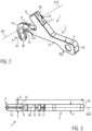
- the Figure 2 shows the transport hook 1 of the Figure 1 in a perspective view without the safety device 7.
- the through hole 10 is visible within a receptacle 6a for the securing device 7, and fastening points 11 in which the fastening plate 7a can be connected to the transport hook 1, for example, screwed or positively received via corresponding connecting elements not shown.
- the Figure 2 the through hole 8 for the safety rod 7c.
- the lever section 2 is designed as a flat body, i.e., it has two flat side walls 12 that run essentially parallel to each other.
- the side walls 12 can also run at an angle to each other, so that a thickness H ( Figure 3 ) and/or a width B of the lever section 2 changes.
- the lever section 2 has a first width B1 directly adjacent to its engagement section 15 and a second width B2 near the free end 2a, which is approximately twice as large as the width B1.
- the transition from the first width B1 to the second width B2 is stepped, but the widening of the lever section 2 over its length can also be continuous.
- the center of the coupling opening 4 can be slightly offset from a central longitudinal axis MLA ( Fig. 4a )) of the remaining lever section 2.
- the offset corresponds approximately to the radius of the coupling opening 4. Since the offset with respect to the central longitudinal axis MLA is directed towards the side on which the hook shank 3 is arranged, the angle ⁇ explained above between the connecting line V and the hook line HL is smaller than without offset, whereby the angling or engagement by the hook shank 3 is more pronounced.
- the Figure 3 shows the transport hook 1 of the Figure 2 in a plan view.
- the transport hook 1 of the exemplary embodiment has a substantially uniform thickness H over its entire length L. This means that a diameter D of the substantially round or circular hook shank 3 corresponds to the thickness of the flat lever section 2.
- the thickness H can also vary, for example, be smaller at the free end 2a than near the free securing end 3c.
- the transport hook 1 is related to a central longitudinal plane MLE (MLE is perpendicular to the plane of the drawing of Fig. 3 ) mirrored. This means that the transport hook 1 can consist of two cast or molded parts that are joined, for example, welded together. This allows the formation of the through holes 8 and 10 in the respective halves, thus eliminating the need for reworking of the transport hook 1.
- MLE central longitudinal plane
- the top view of the Figure 3 shows how the Figure 2 the through hole 8 for the safety rod 7c of the safety device 7, the through hole 10 and the fastening points 11.
- the Figure 4 includes a figure a) showing the transport hook 1 in a side view, a figure b) showing a further embodiment of the transport hook 1 with a free Securing end 3e on the hook shank 3, and a figure c) showing a section through the transport hook 1 of figure a) along the central longitudinal plane MLE and parallel to the side walls 12.
- the transport hook of figure c) comprises an optional magnet 19, in particular a permanent magnet, which additionally secures the transport hook 1 in the hole 102 if the load 101 consists of a magnetic metal or comprises a metal that is attracted by the magnet 19.
- the Figure 4a essentially corresponds to the illustration of the transport hook 1 in the Figure 1 , only without safety device 7. Therefore, please refer to the description of Figure 1 referred to.
- the Figure 4b shows an alternative embodiment of the transport hook 1.
- This transport hook 1 comprises a securing device in the form of a free securing end 3e, which is connected to the engagement section 3c.
- the free securing end 3e protrudes from the engagement section 3c in a direction away from the lever section 2 and extends in the longitudinal direction of the transport hook 1.
- the free securing end 3e and the engagement section 3c thus form a type of double nose, which reliably secures the transport hook 1 in the hole 102 of the load 101 when the transport hook 1 is not or not yet subjected to a tensile force by the transport device.
- the Figure 4c shows a section through the transport hook 1 of the Figure 4a without the securing device 7.
- the paths of the through-holes 8 and 10 within the hook shank 3 and the retaining tab 6 can be seen for the first time.
- the central axis A10 of the through-hole 10 and the central axis A8 of the through-hole 8 are aligned, i.e., the two central axes A8 and A10 coincide. This allows the through-holes 10 and 8 to be created in two work steps from one side, starting with the through-hole 10. It is also possible to drill the through-hole 10 and the through-hole 8 simultaneously with two tools from opposite sides.
- a magnet 14 is further connected to the transport hook 1, for example, glued on or connected by force and/or form fit.
- the magnet 14 forms an additional safeguard if the load 101 to be lifted consists of a magnetic material or comprises magnetic material, for example, metal particles in a reinforced plastic.
- the magnet 14 is preferably a permanent magnet, which Transport hook 1 is secured to the load 101 and which easily detaches from the load 101 when the load 101 is lifted at a preferably predefined weight force.
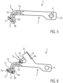
- the Figure 5 shows a transport lever 1 without a retaining tab 6 for connection to a securing device 7.
- the transport hook 1 comprises a securing element 5 in the region of the hook shank 3, which is connected to the engagement section 3c in the pivot joint S.
- the securing element 5 is elastically pretensioned into the illustrated securing position and can be pressed against the tensioning force, for example by hand, against the hook shank 3 in order to be inserted together with the hook shank 3 or the engagement section 3c into the hole 102 of a load 101.
- the securing element 5 Once the securing element 5 has been completely passed through the hole 102, it is automatically moved by the elastic force into the illustrated securing position and thereby secures the transport hook 1 in the hole 102 of the load 101.
- the Figure 6 shows a transport lever 1 with the securing device 7 and the securing element 5, which in this case is elastically pretensioned into a release position in which it rests against the hook shank 3. From this position, it can be moved by the securing device 7 against the elastic force into the illustrated securing position. To do this, the securing rod 7c presses with the free end 7d onto the securing element 5, moving it into the illustrated securing position and securing it in this position.
- the securing rod 7c can be secured in the position shown, for example by means of a locking mechanism (not shown) via the handle 9.
- the handle 9 can be rotated on the securing rod 7c to secure it in the telescopically extended position.
- the elastic restoring force acting on the securing element 5 can then press the securing element 5 back into the release position, whereby the securing rod 7c is simultaneously moved back into the through-hole 8 if the spring force of the securing element 5 is greater than the spring force applied to the securing rod 7c.
- the spring for loading the securing part 7b, 7c, 7e can be omitted entirely. This applies to all of the embodiments explained, since the securing part is then held in a defined position both in the locking position and in the release position without a spring. However, loading with a spring is advantageous, since the securing part always automatically assumes a specific position.
- the spring can also be arranged such that the securing part is pushed into the release position. In this case, however, a locking mechanism should be provided that can fix the securing part in the locking position.
- a transport hook 1 is formed with a movable safety lever 20 on the lever section 2 ( Fig. 9a, 9b ).
- the safety lever 20 is pivotally mounted by means of a pivot joint 21 adjacent to the coupling opening on the side of the lever section 2 from which the hook shank 3 also extends.
- the safety lever 20 can be folded away from the hook shank 3 until the safety lever strikes the hook shank with a stop element 22 and further pivoting movement is blocked ( Fig. 9b ).
- the safety lever 20 rests directly on the lever section 2.
- the transport hook 1 can thus be inserted into a hole 102 of a load 101 with the hook shank 3 and pulled out again, the lever section 2 being arranged approximately parallel to the surface of the load 101 for this purpose.
- the safety lever 20 protrudes from the lever section 2 on the same side as the hook shank 3 ( Fig. 9b ).
- the hook shank engages behind an edge on the hole 102 of a load 101.
- the lever section 2 cannot be brought close to the surface of the load 101, so that the transport hook 1 cannot be removed from the hole 102.
- the safety lever 20 thus forms a movable safety part on the transport hook 1, with which the transport hook can be secured at the hole 102.
- the safety lever can be secured in its end positions with a corresponding fixing device.
- This fixing device can, for example, comprise a spring which is arranged between the lever section 2 and the safety lever 20. is arranged and presses them apart.
- a fixing ring can wrap around the lever section 2 and be moved along the lever section so that it also encloses the safety lever 20 resting against the lever section 2 and holds it in its position resting against the lever section 2 ( Fig. 9a ).
- locking means can be provided which lock the safety lever in its end positions according to Fig. 9a and/or Fig. 9b
- another movable safety part that is not pivotable can also be provided, which can form a projection that can be changed from the lever section 2.
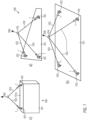
- the Figure 7 shows in the sketch a) by way of example a first lifting system 100, which carries a plate-shaped load 101 or a structure with a plate-shaped section.
- the load 101 comprises three essentially circular holes 102 with a diameter slightly larger than the diameter D of the hook shank 3 ( Figure 3 ) of the transport hooks 1, which pass through the holes 102 of the load 101.
- the transport hooks 1 can be connected via ropes or chains 103 to a lifting device 200, which is shown as a directional arrow in sketch a).
- the ropes 103 can be connected to the lifting device 200, for example, a crane, directly or via a connecting element 104.
- Sketch b) shows a second lifting system 100 that supports a plate-shaped load 101 or a structure with a plate-shaped section.
- the structure 101 comprises four essentially circular holes 102 with a diameter slightly larger than the diameter D of the hook shank 3 ( Figure 3 ) of the transport hooks 1, which pass through the holes 102 of the load 101.
- the transport hooks 1 can be connected via ropes or chains 103 to a lifting device 200, which is shown as a directional arrow in sketch b).
- the ropes 103 can be connected to the lifting device 200, for example, a crane, directly or via a connecting element 104.
- Sketch c) shows a lifting system 100 with a load 101 in the form of a box or a hollow body.
- Two holes 102 are provided in the top side 101 of the load 101, which forms a plate-shaped section, into which transport hooks 1 engage.
- the transport hooks 1 are, as shown in sketches a) and b), Figure 7 connected to a lifting device 200 via ropes 103.
- Sketch a shows the transport hook 1 with the lever section 2 and the hook shank 3, as it is, for example, manually guided to the circular hole 102 of the load 101.
- sketch b shows the hook shank 3 is guided through the circular hole 102 of the load 101 and protrudes downwards from the plate-shaped load 101.
- the lever section 2 of the transport hook 1 lies essentially flat on the upper side 101a of the load 101.
- the transport hook 1 is connected via the coupling opening 4 to a lifting device 200, which is shown in the sketch c) as a directional arrow, for example a crane, and the transport hook 1 is subjected to a tensile force, whereby the transport hook 1 rotates in the hole 102 of the load 101 about a lower edge of the inner circumferential wall 104 and the hook shank 3 is pivoted towards a bottom side 101b of the load 101.
- the position shown in the sketch c) is the final position of the transport hook 1 when the load 101 is lifted with one of the lifting systems 100 of the Figure 7 with several holes 102 and several transport hooks 1.
- the straight line V which connects the point of application of the lifting device 200 on the lever section with the vertex SP of the angle section 14.
- the angle ⁇ between the straight line V and a second straight line on the upper side of the hook shank is less than 90°.
- the single transport hook 1 has been moved by the lifting device 200, which is shown in sketch d) as a directional arrow, into a final position in which the transport hook 1 supports the weight of the load 101.
- the load 101 hangs essentially vertically downwards from the transport hook.
- the plate-shaped section of the load 101 having the hole 102 is thin compared to the hook shank 3.
- a thin load 101 which means that it is thin in the area of the hole 102 compared to the thickness of the hook shank 3, it is sufficient if the hole 102 is only slightly larger than the cross-sectional area or the maximum diameter D of the hook shank 3.
- the maximum hole diameter should preferably not be larger than twice the maximum diameter D of the hook shank 3, in particular not larger than 1.8 times the maximum diameter D of the hook shank 3 or not larger than 1.5 times the maximum diameter D of the hook shank 3 or not larger than 1.3 times the maximum diameter D of the hook shank 3, so that the hook shank and the angle section can be inserted into the hole on the one hand and cannot escape on the other hand when the transport hook is under tension during lifting.
- the thickness of the load in the region of the hole 102 is preferably not greater than 2 times the maximum diameter D of the hook shank 3, in particular not greater than 1.5 times the maximum diameter D of the hook shank 3 or not greater than 1.3 times the maximum diameter D of the hook shank 3.
- the maximum hole diameter should be smaller than one hook shank length HSL (Fig. 3 a)), which is the distance between the free end 3b of the hook shank and the side of the lever section 2 remote from the hook shank 3.
- the maximum diameter of the hole is preferably smaller than 0.8 times the hook shank length HSL, in particular smaller than 0.7 times the hook shank length HSL or smaller than 0.5 times the hook shank length HSL or smaller than 0.3 times the hook shank length HSL. This limits the maximum thickness of the load in the area of the hole.
- the hole 102 is preferably circular. It may also deviate from the circular shape, whereby it is expedient that the smallest hole diameter is different from the largest hole diameter. does not deviate by more than 50%, preferably not more than 25% and in particular not more than 10%.
- the Figures 10a - 10c show the transport hook 1 of the Figure 1 in a modified form.
- the transport hook 1 comprises the lever section 2 with the coupling opening 4 and the hook shank 3, which can pass through a hole 102 of a load 101 (both not shown) in order to lift and transport the load 101 by means of a lifting system 100 (not shown).
- the transport hook 1 comprises a securing device with which it can be secured in the hole 102 or is secured when the transport hook 1 is subjected to a tensile force by the lifting system 100, so that the transport hook 1 cannot be inadvertently moved out of the hole 102 when the securing device is active.
- the transport hook 1 comprises a wing element 18, which can consist of two separate wings 18.1 and 18.2.
- the wing element 18 is connected to the transport hook 1 on an underside 2b of the transport hook 1 facing the hook shank 3, preferably firmly connected by means of adhesion, material or force fit, etc.
- the wings 18.1 and 18.2 are in a plan view of the transport hook 1, as shown in FIG. Figure 10a ) shows, to the side of the transport hook 1.
- the transport hook 1 has a diameter D in the area in which the wing element 18 or the wings 18.1, 18.6 is/are connected to the transport hook 1 (see Figure 2 ).
- the distance AFF between the outer ends 18.1a, 18.2a, i.e., those pointing away from the transport hook 1, can then, for example, correspond approximately to twice the diameter D of the transport hook 1 in this area.
- the distance AFF can also be larger or smaller.
- the distance AFF can also be referred to as the span of the wing element 18.
- the wing element 18 can, in the state connected to the transport hook 1, protrude below the lower surface 2b of the lever section 2 or of the transport hook 1 in the vicinity of the connection area with the wing element 18, as shown, or be arranged in a recess not explicitly shown, so that the wing element 18 does not protrude beyond the underside of the transport hook 1, but is preferably flat with the surrounding surface of the transport hook 1.
- the transport hook 1 further comprises a nose 23, which is formed on an upper side of the transport hook 1.
- the nose 23 is in the illustrated embodiment dormer-shaped from the upper side 2c facing away from the hook leg 3.
- the nose 23 has a flat front side 23a facing the retaining tab 6, which in the illustrated embodiment runs essentially parallel to the outer surface 6b of the retaining tab 6 facing the nose 23.
- the nose 23 is connected to the transport hook 1 in the area in which an opening of the through-bore 8 is located, which forms an opening and guide for the securing rod 7c in the angled section 14.
- the nose 23 extends the through-bore 23, and the front side 23a advantageously forms a flat mounting surface for a drill for creating the through-bore 8 in the angled section 14 of the transport hook 1.
- the nose extends the guide area for the securing rod 7c, and the securing rod 7c is better protected in the extended through-bore 8.
- the upper side of the nose 23 can run parallel to a central longitudinal axis (not shown) of the securing rod 7c.
- the height HN of the nose 23 in the area of the front side 23a, perpendicular to the central axis of the securing rod 7c, can be selected such that the nose 23 completely covers the handle 9 when viewed from the front onto the transport hook 1. This prevents the handle 9 from being accidentally released from the shown securing position when the load is being gripped or transported.
- the last-described nose 23 reliably prevents, for example, a cable of the lifting system 100 or an unevenness of the load 101 from accidentally moving the handle, thus jeopardizing the safety of the transport.
- the nose 23 can have a distance NT from a tangent T, which rests on the surface of a frontmost end of the transport hook 1, which distance depends on the diameter D of the hook shank 3 and/or the angled section 14.
- the distance NT can preferably be approximately twice the diameter D. However, the distance NT can also be smaller or larger than twice the diameter.
- the height HN of the front side 23a can be determined by an extension part 24, which is part of the nose 23 and is formed together with the nose 23 or is formed separately from the nose 23 and subsequently connected to the nose 23.
- the extension part 24 can be made of a material different from the material of the nose 23 made of a different material, such as plastic, and can be replaced if it becomes worn or damaged.
- the nose 23 can also comprise a securing element with which the securing rod 7c can be secured in the securing position and preferably also in the rest position.
- This securing element can be, for example, a slider that engages or snaps into recesses on the securing rod 7c.
- the extension 24 can form the securing element.
- Other known mechanisms for securing the securing rod 7c in fixed positions relative to the through-bore 8 are encompassed by the invention. With such a solution, the retaining tab 6 can be omitted entirely, which leads to material and cost savings.
- Figure 10b shows an embodiment in which the handle 9 forms the end of the safety rod 7c.
- the retaining tab 6 can be plate-shaped, with a thickness in the longitudinal direction of the transport hook 1 which is considerably smaller than in the Figure 10b shown, for example a steel plate with a thickness of 3 mm or 0.5 cm or 1 cm or another dimension.
- the spring element (not shown) which pretensions the securing rod 7c into the securing position or the rest position would lie outside the retaining tab 6 and be supported with one end on an outer side of the retaining tab and with the other end on the handle.
- the spring is preferably a helical spring which encloses the securing rod 7c.
- no fastening plate 7a as provided in the exemplary embodiments explained above, is necessary.
- the spring element can be protected against contamination by an elastic sheath.
Landscapes
- Engineering & Computer Science (AREA)
- Mechanical Engineering (AREA)
- Hooks, Suction Cups, And Attachment By Adhesive Means (AREA)
- Forklifts And Lifting Vehicles (AREA)
- Materials For Medical Uses (AREA)
- Load-Engaging Elements For Cranes (AREA)
Description
- Die Erfindung betrifft einen Transporthaken zum Anheben und Bewegen einer Last, wie z.B. Bodenelemente, die dicht aneinandergelegt werden und nur von oben zugänglich sind.
- Es ist schwierig Behälter, Rahmen, Fertigteile, Teile von Modulbauten oder anderen Gegenständen, wie Maschinen, die beispielsweise derart verbaut sind oder verbaut werden müssen, dass sie nicht von der Seite oder an der Unterseite gegriffen werden können, anzuheben und im Raum zu bewegen. Hier wäre es vorteilhaft, wenn die Behälter etc. einfach aber sicher an einer Oberseite die einer Hebevorrichtung zugewandt mit der Hebevorrichtung verbunden werden könnten.
- Aus der
US 2008/0292397 A1 ist eine Bodenbelag-Trägerstruktur bekannt, mit einer Vielzahl längs ausgerichteter Bretter, die aneinander befestigt sind. Die Bodenbelag-Trägerstruktur weist wenigstens zwei Kopplungsöffnungen in Form von Langlöchern auf, die in einem vorgegebenen Abstand parallel zueinander verlaufen. Alternativ kann der Doppelhaken seitlich in die Bodenbelag-Trägerstruktur eingreifen. Ein Doppelhaken kann durch die Löcher in das Innere der Bodenbelag-Trägerstruktur eingreifen, der Doppelhaken kann mit einer Hebevorrichtung verbunden werden. - Die
US 9,741,847 B2 - Die
US 845,724 offenbart ein stiftförmiges Element, das an einer Basis befestigt ist, um in ein Bohrloch eines Steinblockes gesteckt werden zu können. Durch Reibschluss in dem Bohrloch kann der Steinblock angehoben werden. Die Basis steht über dem Stift seitlich vor und stützt sich an der Oberfläche des Steinblocks ab. Hierdurch entsteht eine Verkeilung. - Aus der
DE 10 2016 222 787 A1 geht ein Transporthaken hervor, der durch ein Loch gesteckt werden kann und im Randbereich dieses Loches mittels einer Sicherungseinrichtung hintergreift. - In der
US 1,373,438 ist eine selbstklemmende Hubeinrichtung offenbart, um Steinblöcke anzuheben. Diese weist einen stiftförmigen Körper auf, an dem im rechten Winkel ein Schenkel angebunden ist. An dem Schenkel ist schwenkbar ein Klemmhebel befestigt. An einem Ende des Klemmhebels ist ein Kopplungselement zum Befestigen eines Seiles vorgesehen. Das andere Ende des Klemmhebels weist eine Kante auf, die gegen die Oberfläche eines Steinblocks gedrückt wird, wenn der stiftförmige Abschnitt in eine entsprechende Bohrung in den Steinblock eingesetzt wird. - Die
US R E28 709 E betrifft einen Hebehaken, der eine Endschlaufe eines Tragseils aufnehmen kann, und eine Sicherheitsklappe, die schwenkbar am Hebehaken angebracht ist und so geformt ist, dass sie die Endschlaufe des Tragseils am Haken hält. - Aus der
JP S57 141979 U - Die
JP H01 132686 U - In der
JP S57 57188 A - Die
FR 2 677 969 A1 - In der
GB 2 417 521 A - Die Sperrklinke ist mit einem Zugelement verbunden, sodass die Sperrklinke eine Öffnung des Hebehakens von selbst wieder verschließt, sobald beispielsweise ein Seil in die Öffnung eingebracht wurde.
- Es ist Aufgabe der Erfindung einen Transporthaken und ein Hubsystem zur Verfügung zu stellen, mit welchen eine Last sicher gegriffen, angehoben und gefahrlos im Raum bewegt werden kann. Eine weitere Aufgabe ist das Bereitstellen eines geeigneten Verfahrens.
- Diese Aufgaben werden durch den Gegenstand des unabhängigen Anspruchs 1 gelöst.
- Vorteilhafte Ausgestaltungen sind in den Unteransprüchen angegeben.
- Im Folgenden wird die Erfindung anhand von Figuren näher erläutert. Die Figuren zeigen Ausführungsbeispiele eines Transporthakens, ohne dass dadurch der Umfang auf diese Ausführungsbeispiele eingeschränkt werden soll.
- Die Figuren zeigen im Einzelnen:
- Figur 1:
- Transporthaken mit Sicherungsvorrichtung in einer Ansicht von der Seite;
- Figur 2:
- Transporthaken der
Figur 1 ohne Sicherungsvorrichtung in einer perspektivischen Ansicht; - Figur 3:
- Draufsicht auf Transporthaken der
Figur 2 ; - Figur 4a-4c:
- Transporthaken der
Figur 2 von der Seite und in einer Schnittansicht entlang einer Mittellängsachse; - Figur 5:
- Transporthaken mit in die Sicherungsposition vorgespanntem Sicherungselement;
- Figur 6:
- Transporthaken mit Sicherungselement, das mittels der Sicherungsvorrichtung in die Sicherungsposition gedrückt und dort gehalten wird;
- Figur 7a-7c:
- Skizze von Hubsystem mit zwei bzw. drei Transporthaken;
- Figur 8a-8d:
- skizzenhafte Darstellung der Verfahrensschritte zum Greifen und Anheben einer Last mit einem Transporthaken;
- Figur 9a, 9b:
- Transporthaken mit einem weiteren Sicherungselement in der Löseposition und Sicherungsposition; und
- Figur 10a-10c:
- Transporthaken mit Sicherungsvorrichtung mit Flügeln und Nase.
- Die
Figur 1 zeigt einen Transporthaken 1 mit dem eine Last 101, beispielsweise ein Bodenelement eines Eventzeltes, angehoben werden kann. - Der Transporthaken 1 umfasst einen Hebelabschnitt 2, einen Hakenschenkel 3 und eine Haltelasche 6, die mit einer Sicherungsvorrichtung 7 verbunden ist, mit der der Transporthaken 1 im Eingriff mit und in einem teilweisen Durchgriff durch ein Loch 102 der Last 101 gesichert werden kann.
- Der Hebelabschnitt 2 hat ein freies Ende 2a und eine als Kopplungselement fungierende Kopplungsöffnung 4, nahe einem vom Hakenschenkel 3 entfernten freien Ende 2a. An den Hakenschenkel 3 schließt sich ein Winkelabschnitt 14 an, der den Hakenschenkel und den Hebelabschnitt2 verbindet. Der Winkelabschnitt ist gebogen, so dass der Hebelabschnitt 2 und der Hakenschenkel 3 in einem Winkel zueinander angeordnet sind.
- Der Hebelabschnitt 2 weist angrenzend zum Winkelabschnitt 14 einen Eingriffsbereich 15 auf, der im Wesentlichen die gleiche Querschnittsform wie der Winkelabschnitt 14 und der Hakenschenkel 3 aufweist um, wie es unten näher erläutert wird, in bestimmten Situationen in ein Loch 102 einer Last 101 einzugreifen.
- Im vorliegenden Ausführungsbeispiel weisen der Eingriffsbereich 15, der Winkelabschnitt 14 und der Hakenschenkel 3 einen in etwa kreisförmigen Querschnitt auf, der seitlich etwas abgeflachte Flächen 16 besitzt. Vorzugsweise ist der Querschnitt im Wesentlichen kantenfrei geformt, so dass er sich in einem Loch 102 frei um eine Lochachse 105 drehen kann, welche mittig durch das Loch 102 verläuft und senkrecht auf einem plattenförmigen Abschnitt der Last steht, in dem das Loch 102 eingebracht ist. Im wesentlichen kantenfrei bedeutet, dass an Kanten nur ein stumpfer Winkel von bspw. mehr als 100° und insbesondere mehr als 150° ausgebildet ist. Bei solchen Kanten ist die Gefahr einer Verhakung mit am Lochrand ausgebildeten Vorsprüngen gering. So bilden die abgeflachten Flächen 16 in dem in
Fig. 1 gezeigten Ausführungsbeispiel mit den sich im Querschnitt etwa kreisförmigen Oberflächen jeweils Kanten 17 aus, die einen derart stumpfen Winkel einschließen, dass keine Verhakungsgefahr besteht. - Der Hakenschenkel 3 ist aus einem Eingriffsabschnitt 3a und einem vom Winkelabschnitt entfernten freien Ende 3b ausgebildet, das eine stumpfe Form besitzt, bspw. in Form eines Kugelsegmentes.
- Im Ausführungsbeispiel ist der Transporthaken 1 einstückig gebildet oder aus einem Stück urgeformt. Das heißt, dass der Transporthaken 1 beispielsweise aus einem Plattenmaterial ausgeschnitten, in einem Gussverfahren hergestellt, aus Pulver gepresst oder aus einem Halbzeug geschmiedet wurde.
- Die Sicherungsvorrichtung 7 umfasst eine Befestigungsplatte 7a und ein Sicherungsteil, das im vorliegenden Ausführungsbeispiel aus einem Hohlzylinder 7b und einer Sicherungsstange 7c mit einem freien Ende 7d ausgebildet ist. Das Sicherungsteil umfasst ferner einen Griff 9, der mit der Sicherungsstange 7c verbunden ist. Der Hohlzylinder 7b besitzt ein Innengewinde und der rückwärtige Bereich der Sicherungsstange 7c ein Außengewinde, welche miteinander in Eingriff stehen. Mit einer Kontermutter 7e ist einerseits der scheibenförmige Griff 9 am Sicherungsteil fixiert und kann andererseits die relative Position der Sicherungsstange 7c zum Hohlzylinder 7b eingestellt werden. Hierdurch kann die Länge des Sicherungsteils eingestellt und an die Größe des Lochs 102 einer Last 101 angepasst werden, die mit dem Transporthaken 1 angehoben werden soll.
- Der Hohlzylinder 7b ist verschieblich in einer Durchgangsbohrung 10 der Haltelasche 6 gelagert. In der Durchgangsbohrung 10 ist eine Druckfeder (nicht dargestellt) angeordnet, welche sich an der Befestigungsplatte 7a abstützt und das Sicherungsteil 7b, 7c, 7e mit einer Kraft beaufschlagt, welche das Sicherungsteil weg von Haltelasche 6 drückt.
- Die Sicherungsstange 7c ist in einer Durchgangsbohrung 8 verschieblich gelagert, welche sich durch den Winkelabschnitt 14 erstreckt und an der von der Haltelasche 6 entfernten Seite am Hakenschenkel 3 mündet, so dass die Sicherungsstange in einer Sicherungsposition mit ihrem freien Ende 7d am Hakenschenkel 3 vorsteht (
Fig. 1 ). - Die Durchgangsbohrungen 8, 10 fluchten zueinander, d.h., dass eine Mittelachse A10 der Bohrung 10 mit einer Mittelachse A8 der Bohrung 8 zusammenfällt.
- Im vorliegenden Ausführungsbeispiel dient der Griff 9 auch als Anschlag zur Begrenzung der Bewegung des Sicherungsteils 7b, 7c, 7e zwischen der Sicherungsposition und einer Löseposition.
- In der Sicherungsposition steht der Sicherungsstift 7c am Hakenschenkel 3 mit seinem freien Ende 7d vor und der Griff 9 schlägt am Hebelabschnitt 2 am Eingriffsbereich 15 an. In der Löseposition ist der Sicherungsstift 7c mit seinem freien Ende 7d vollständig in die Durchgangsbohrung 8 des Transporthakens 1 eingezogen und der Griff 9 schlägt an der Haltelasche 6 an. Das Sicherungsteil kann somit bzgl. der Durchgangsbohrung 10 aus- und einteleskopieren.
- In dieser Löseposition kann die Sicherungsstange optional mittels eines Rastmechanismus (nicht dargestellt) festgelegt werden, so dass die Sicherungsstange zum Beispiel im Lager oder beim Transport des Transporthakens zu einem Einsatzort vorteilhaft vor Beschädigung geschützt ist. Dieser Rastmechanismus kann bspw. durch Drehen des Sicherungsteils um seine Längsachse mittels des Griffs 9 betätigt werden. Der Rastmechanismus kann auch so ausgebildet sein, dass mit dem Griff 9 oder auf andere Weise das Sicherungsteil auch in der Sicherungsposition gesichert werden kann, so dass es sich nicht ungewollt zurück in die Löseposition bewegen kann.
- Die Befestigungsplatte 7a kann eine Durchgangsbohrung aufweisen, durch die das Sicherungsteil in der Löseposition über die Sicherungsplatte 7a nach hinten vorsteht. Diese Durchgangsbohrung bildet dann eine weitere Linearführung für das Sicherungsteil. Im vorliegenden Ausführungsbeispiel ist die Befestigungsplatte 7a ohne Durchgangsbohrung ausgebildet. Die Befestigungsplatte kann alternativ zum Griff 9 einen Anschlag für das Sicherungsteil bilden, um dessen Bewegung in die Löseposition zu begrenzen.
- Der Winkelabschnitt 14 verbindet den Eingriffsbereich 15 mit dem Hakenschenkel 3 in einem Winkel, wobei der Winkel im Ausführungsbeispiel kleiner als 90° ist. In anderen Ausführungen des Transporthakens kann der Winkel ca. 90° oder 90° sein. Eine Verbindungslinie V, die sich durch einen Kopplungspunkt und einem Scheitelpunkt SP des Winkelabschnitts 15 erstreckt. Der Kopplungspunkt ist der Verbindungspunkt, an dem bspw. eine Hebevorrichtung angreift, um den Transporthaken 1 anzuheben. Im vorliegenden Ausführungsbeispiel ist der Kopplungspunkt der Mittelpunkt 4A der Kopplungsöffnung 4, in dem der Transporthaken 1 mit der Hebevorrichtung 200 verbindbar ist. Der Scheitelpunkt SP ist an der inneren Oberfläche des Winkelabschnitts angeordnet. Eine Hakenlinie HL läuft entlang der Innenseite des Hakenschenkels 3. Die Verbindungsline V und die Hakenlinie HL schneiden sich in einem Winkel α der kleiner als 90° und bevorzugt kleiner als 85° und insbesondere kleiner als 80° bzw. kleiner als 75° ist.
- Je kleiner der Winkel α ist, desto stärker hintergreift der Hakenschenkel 3 einen plattenförmigen Abschnitt einer Last, in dem in einem Loch der Transporthaken 1 eingehängt ist und desto weniger ist es notwendig, den Hebelabschnitt 2 senkrecht zum plattenförmigen Abschnitt der Last anzuordnen.
- Der Hakenschenkel 3 kann teilweise eine Ummantelung oder Beschichtung 13 aufweisen, die beispielsweise eine rutschhemmende Oberfläche hat und/oder aus einem elastischen Material besteht, um eine Beschädigung der Lochkanten abzumildern oder zu verhindern.
- Die
Figur 2 zeigt den Transporthaken 1 derFigur 1 in einer perspektivischen Ansicht ohne die Sicherungsvorrichtung 7. In derFigur 2 ist die Durchgangsbohrung 10 innerhalb einer Aufnahme 6a für die Sicherungsvorrichtung 7 zu sehen, und Befestigungspunkte 11 in denen die Befestigungsplatte 7a mit dem Transporthaken 1 verbunden, zum Beispiel verschraubt oder über entsprechende nicht gezeigte Verbindungselemente formschlüssig aufgenommen werden kann. Außerdem zeigt dieFigur 2 die Durchgangsbohrung 8 für die Sicherungsstange 7c. - Im Ausführungsbeispiel ist der Hebelabschnitt 2 als Flachkörper ausgebildet, das heißt, er weist zwei flache Seitenwände 12 auf, die im Wesentlichen parallel zueinander verlaufen. Die Seitenwände 12 können auch in einem Winkel zueinander verlaufen, so dass sich über die Länge L oder einen Teil der Länge des Hebelabschnitts eine Dicke H (
Figur 3 ) und/oder eine Breite B des Hebelabschnitts 2 ändert. - Der Hebelabschnitt 2 weist direkt neben seinem Eingriffsabschnitt 15 eine erste Breite B1 auf und nahe dem freien Ende 2a eine zweite Breite B2, die in etwa doppelt so groß ist, wie die Breite B1. Im Ausführungsbeispiel ist der Übergang von der ersten Breite B1 zur zweiten Breite B2 stufenförmig, die Verbreiterung des Hebelabschnitts 2 über seine Länge kann aber auch kontinuierlich erfolgen.
- Die Verbreiterung ist derart ausgebildet, dass sie zur gleichen Seite wie der Hakenschenkel 3 weist. Hierdurch kann der Mittelpunkt der Kopplungsöffnung 4 ein Stück von einer Mittellängsachse MLA (
Fig. 4a )) des übrigen Hebelabschnittes 2 versetzt sein. Im vorliegenden Ausführungsbeispiel entspricht der Versatz etwa dem Radius der Kopplungsöffnung 4. Da der Versatz bzgl. der Mittellängsachse MLA zu der Seite gerichtet ist, an der der Hakenschenkel 3 angeordnet ist, ist der oben erläuterte Winkel α zwischen der Verbindungsline V und der Hakenlinie HL kleiner als ohne Versatz, wodurch Abwinklung bzw. Hintergreifung durch den Hakenschenkel 3 stärker ausgeprägt ist. - Die
Figur 3 zeigt den Transporthaken 1 derFigur 2 in einer Draufsicht. Der Transporthaken 1 des Ausführungsbeispiels weist über seine gesamte Länge L eine im Wesentlichen einheitliche Dicke H auf. Das heißt, ein Durchmesser D des im Wesentlichen runden oder kreisrunden Hakenschenkels 3 entspricht der Dicke des flachen Hebelabschnitts 2. Die Dicke H kann auch variieren, zum Beispiel am freien Ende 2a kleiner sein als nahe dem freien Sicherungsende 3c. - Der Transporthaken 1 ist bezogen auf eine Mittellängsebene MLE (MLE steht senkrecht auf die Zeichenebene von
Fig. 3 ) gespiegelt ausgebildet. Das heißt, der Transporthaken 1 kann aus zwei Guss- oder Formteilen bestehen, die miteinander gefügt, beispielsweise miteinander verschweißt werden. Dies erlaubt die Ausbildung der Durchgangsbohrungen 8 und 10 in den jeweiligen Hälften und erspart dadurch eine Nachbearbeitung des Transporthakens 1. - Die Draufsicht der
Figur 3 zeigt wie dieFigur 2 die Durchgangsbohrung 8 für die Sicherungsstange 7c der Sicherungsvorrichtung 7, die Durchgangsbohrung 10 und die Befestigungspunkte 11. - Die
Figur 4 umfasst eine Abbildung a), die den Transporthaken 1 in einer Seitenansicht zeigt, eine Abbildung b) die eine weitere Ausführung des Transporthakens1 mit einem freien Sicherungsende 3e am Hakenschenkel 3 zeigt, und eine Abbildung c) die einen Schnitt durch den Transporthaken 1 der Abbildung a) entlang der Mittellängsebene MLE und parallel zu den Seitenwänden 12 zeigt. Der Transporthaken der Abbildung c) umfasst einen optionalen Magneten 19, insbesondere einen Dauermagneten, der den Transporthaken 1 zusätzlich in dem Loch 102 sichert, wenn die Last 101 aus einem magnetischem Metall besteht oder ein Metall umfasst, das von dem Magnet 19 angezogen wird. - Die
Abbildung 4a entspricht im Wesentlichen der Abbildung des Transporthakens 1 in derFigur 1 , nur ohne Sicherungsvorrichtung 7. Es wird daher auf die Beschreibung zurFigur 1 verwiesen. - Die
Abbildung 4b zeigt eine alternative Ausführung des Transporthakens 1. Dieser Transporthaken 1 umfasst eine Sicherung in Form eines freien Sicherungsendes 3e, das mit dem Eingriffsabschnitt 3c verbunden ist. Das freie Sicherungsende 3e ragt von dem Eingriffsabschnitt 3c ab, in eine Richtung, die von dem Hebelabschnitt 2 weg weist und sich in Längsrichtung des Transporthakens 1 erstreckt. Das freie Sicherungsende 3e und der Eingriffsabschnitt 3c bilden dadurch eine Art Doppelnase, die den Transporthaken 1 zuverlässig in dem Loch 102 der Last 101 sichert, wenn der Transporthaken 1 nicht oder noch nicht durch die Transportvorrichtung mit einer Zugkraft beaufschlagt wird. - Die
Abbildung 4c zeigt einen Schnitt durch den Transporthaken 1 derAbbildung 4a ohne die Sicherungsvorrichtung 7. In dieser Abbildung sind erstmals die Verläufe der Durchgangsbohrungen 8 und 10 innerhalb des Hakenschenkels 3 bzw. der Haltelasche 6 zu sehen. Dabei wird offensichtlich, dass die Mittelachse A10 der Durchgangsbohrung 10 und die Mittelachse A8 der Durchgangsbohrung 8 auf einer Linie liegen, das heißt, die beiden Mittelachsen A8 und A10 fallen zusammen. Dies erlaubt, dass die Durchgangsbohrungen 10 und 8 in zwei Arbeitsschritten von einer Seite, beginnend mit der Durchgangsbohrung 10, erzeugt werden können. Möglich ist auch eine gleichzeitige Bohrung der Durchgangsbohrung 10 und der Durchgangsbohrung 8 mit zwei Werkzeugen von entgegengesetzten Seiten. - In der ist ferner ein Magnet 14 mit dem Transporthaken 1 verbunden, zum Beispiel aufgelebt oder durch Kraft- und/oder Formschluss verbunden. Der Magnet 14 bildet eine zusätzliche Sicherung, wenn die zu hebende Last 101 aus einem magnetischen Material besteht oder magnetisches Material, beispielsweise Metallpartikel in einen verstärkten Kunststoff, umfasst. Bei dem Magneten 14 handelt es sich bevorzugt um einen Dauermagneten, der den Transporthaken 1 auf der Last 101 sichert, und der sich bei einem Anheben der Last 101 bei einer bevorzugt vorgebbaren Gewichtskraft problemlos von der Last 101 löst.
- Die
Figur 5 zeigt einen Transporthebel 1 ohne Haltelasche 6 zum Verbinden mit einer Sicherungsvorrichtung 7. Zum Sichern des Transporthakens 1 in einem Loch 102 einer Last 101 umfasst der Transporthaken 1 im Bereich des Hakenschenkels 3 ein Sicherungselement 5, das in dem Schwenkgelenk S mit dem Eingriffsabschnitt 3c verbunden ist. Das Sicherungselement 5 ist elastisch in die gezeigte Sicherungsposition vorgespannt und kann gegen die Spannkraft beispielsweise von Hand an den Hakenschenkel 3 angedrückt werden, um zusammen mit dem Hakenschenkel 3 beziehungsweise dem Eingriffsabschnitt 3c in das Loch 102 einer Last 101 eingeführt zu werden. Ist das Sicherungselement 5 vollständig durch das Loch 102 hindurchgeführt, wird es automatisch durch die elastische Kraft in die gezeigte Sicherungsposition bewegt und sichert dadurch den Transporthaken 1 in dem Loch 102 der Last 101. - Die
Figur 6 zeigt einen Transporthebel 1 mit der Sicherungsvorrichtung 7 und dem Sicherungselement 5, das in diesem Fall elastisch in eine Löseposition vorgespannt ist, in der es an dem Hakenschenkel 3 anliegt. Aus dieser Position kann es durch die Sicherungsvorrichtung 7 gegen die elastische Kraft in die gezeigte Sicherungsposition bewegt werden. Dazu drückt die Sicherungsstange 7c mit dem freien Ende 7d auf das Sicherungselement 5, bewegt es in die gezeigte Sicherungsposition und legt es in dieser Position fest. - Zum Festlegen des Sicherungselements 5 in der Sicherungsposition kann die Sicherungsstange 7c in der gezeigten Position zum Beispiel mittels eines Rastmechanismus (nicht gezeigt) über den Griff 9 gesichert werden, zum Beispiel kann der Griff 9 auf der Sicherungsstange 7c verdreht werden, um sie in der austeleskopierten Position zu sichern. Zum Herausnehmen des Transporthakens 1 aus dem Loch 102 der Last 101 muss dann nur die Sicherung der Sicherungsstange 7c durch den Griff 9 gelöst werden. Die auf das Sicherungselement 5 wirkende elastische Rückstellkraft kann dann das Sicherungselement 5 zurück in die Löseposition drücken, wodurch gleichzeitig die Sicherungsstange 7c zurück in die Durchgangsbohrung 8 bewegt wird, wenn die Federkraft des Sicherungselementes 5 größer als die Federkraft ist, mit der die Sicherungsstange 7c beaufschlagt wird.
- Wenn ein Rastmechanismus zum Festlegen des Sicherungsteils in der Sicherungsposition und in der Löseposition vorgesehen ist, dann kann die Feder zum Beaufschlagen des Sicherungsteils 7b, 7c, 7e, vollständig weggelassen werden. Dies gilt für alle erläuterten Ausführungsformen, da dann das Sicherungsteil in der Sicherungsposition als auch in der Löseposition ohne Feder definiert gehalten wird. Eine Beaufschlagung mit einer Feder ist jedoch vorteilhaft, da das Sicherungsteil immer selbsttätig eine bestimmte Position einnimmt. Die Feder auch so angeordnet sein, dass das Sicherungsteil in die Löseposition gedrückt wird. Dann sollte jedoch ein Rastmechanismus vorgesehen sein, der das Sicherungsteil in der Sicherungsposition festlegen kann.
- Ein Transporthaken 1 gemäß einer weiteren Ausführungsform ist mit einem beweglichen Sicherungshebel 20 am Hebelabschnitt 2 ausgebildet (
Fig. 9a, 9b ). Der Sicherungshebel 20 ist schwenkbar mittels einem Schwenkgelenk 21 benachbart zur Kopplungsöffnung auf der Seite des Hebelabschnitts 2 schwenkbar befestigt, von der sich auch der Hakenschenkel 3 weg erstreckt. Der Sicherungshebel 20 kann ein Stück vom Hakenschenkel 3 weggeklappt werden, bis der Sicherungshebel mit einem Anschlagselement 22 am Hakenschenkel anschlägt und eine weitere Schwenkbewegung gesperrt ist (Fig. 9b ). - In der Löseposition (
Fig. 9a ) liegt der Sicherungshebel 20 unmittelbar am Hebelabschnitt 2 an. Der Transporthaken 1 kann so in ein Loch 102 einer Last 101 mit dem Hakenschenkel 3 eingeführt und wieder herausgezogen werden, wobei der Hebelabschnitt 2 hierzu etwa parallel zur Oberfläche der Last 101 angeordnet ist. - In der Sicherungsposition steht der Sicherungshebel 20 vom Hebelabschnitt 2 auf der gleichen Seite wie der Hakenschenkel 3 ab (
Fig. 9b ). Hierdurch hintergreift der Hakenschenkel einen Rand am Loch 102 einer Last 101. Der Hebelabschnitt 2 kann nicht an die Oberfläche der Last 101 herangeführt werden, so dass der Transporthaken 1 nicht aus dem Loch 102 entfernt werden kann. - Der Sicherungshebel 20 bildet somit ein bewegliches Sicherungsteil am Transporthaken 1, mit dem der Transporthaken am Loch 102 gesichert werden kann.
- Der Sicherungshebel kann in seinen Endpositionen mit einer entsprechenden Fixiereinrichtung gesichert werden. Diese Fixiereinrichtung (nicht dargestellt) kann bspw. eine Feder umfassen, welche zwischen dem Hebelabschnitt 2 und dem Sicherungshebel 20 angeordnet ist und diese auseinander drückt. Ein Fixierring kann den Hebelabschnitt 2 umschlingen und entlang dem Hebelabschnitt verschoben werden, so dass er den an den Hebelabschnitt 2 anliegenden Sicherungshebel 20 auch umschließt und ihn in seiner am Hebelabschnitt 2 anliegenden Position (
Fig. 9a ) sichert. Durch Verschieben des Sicherungsringes in Richtung zum Hakenschenkel 3 kann der Sicherungshebel 20 freigegeben werden. Es können auch an Stelle der Feder oder zusätzlich zur Feder Rastmittel vorgesehen sein, welche den Sicherungshebel in seinen Endpositionen gemäßFig. 9a und/oderFig. 9b fixieren. An Stelle eines schwenkbaren Sicherungshebel kann auch ein anderes bewegliches Sicherungsteil, das nicht schwenkbar ist, vorgesehen sein, das einen vom Hebelabschnitt 2 veränderlichen Vorsprung ausbilden kann. - Die
Figur 7 zeigt in der Skizze a) beispielhaft ein erstes Hubsystem 100, das eine plattenförmige Last 101 oder einen Baukörper mit einem plattenförmigen Abschnitt trägt. Die Last 101 umfasst drei im Wesentlichen kreisrunde Löcher 102 mit einem Durchmesser, der wenig größer ist als der Durchmesser D des Hakenschenkels 3 (Figur 3 ) der Transporthaken 1, die die Löcher 102 der Last 101 durchgreifen. Die Transporthaken 1 können über Seile oder Ketten 103 mit einer Hebevorrichtung 200, die in der Skizze a) als Richtungspfeil dargestellt ist, verbunden werden. Die Seile 103 können direkt oder über ein Verbindungselement 104 mit der Hebevorrichtung 200, beispielsweise einem Kran, verbunden sein. - Die Skizze b) zeigt ein zweites Hubsystem 100 , das eine plattenförmige Last 101 oder einen Baukörper mit einem plattenförmigen Abschnitt trägt. Der Baukörper 101 umfasst vier im Wesentlichen kreisrunde Löcher 102 mit einem Durchmesser, der wenig größer ist als der Durchmesser D des Hakenschenkels 3 (
Figur 3 ) der Transporthaken 1, die die Löcher 102 der Last 101 durchgreifen. Die Transporthaken 1 können über Seile oder Ketten 103 mit einer Hebevorrichtung 200, die in der Skizze b) als Richtungspfeil dargestellt ist, verbunden werden. Die Seile 103 können direkt oder über ein Verbindungselement 104 mit der Hebevorrichtung 200, beispielsweise einem Kran, verbunden sein. - Die Skizze c) zeigt ein Hubsystem 100 mit einer Last 101 in Form einer Kiste oder eines Hohlkörpers. In der Oberseite 101 der Last 101, welche einen plattenförmigen Abschnitt bildet, sind zwei Löcher 102 eingebracht, in die Transporthaken 1 eingreifen. Die Transporthaken 1 sind, wie in den Skizzen a) und b) der
Figur 7 über Seile 103 mit einer Hebevorrichtung 200 verbunden. - In der
Figur 8 sind in vier Handskizzen Verfahrensschritte dargestellt, die notwendig sind, um mit einem oder mehreren Transporthaken 1 eine Last 101 mit einem im Wesentlichen kreisrunden Loch 102 in einem plattenförmigen Abschnitt zu greifen und anzuheben. - Die Skizze a) zeigt den Transporthaken 1 mit dem Hebelabschnitt 2 und dem Hakenschenkel 3, wie er beispielsweise von Hand an das kreisrunde Loch 102 der Last 101 herangeführt wird. In der Skizze b) ist der Hakenschenkel 3 durch das kreisrunde Loch 102 der Last 101 hindurchgeführt und ragt nach unten aus der plattenförmigen Last 101 heraus. Der Hebelabschnitt 2 des Transporthakens 1 liegt im Wesentlichen plan auf der Oberseite 101a der Last 101 auf.
- In der Skizze c) ist der Transporthaken 1 über die Kopplungsöffnung 4 mit einer Hebevorrichtung 200, die in der Skizze c) als Richtungspfeil dargestellt ist, beispielsweise einem Kran, verbunden und der Transporthaken 1 wird mit einer Zugkraft beaufschlagt, wodurch die der Transporthaken 1 in dem Loch 102 der Last 101 um eine Unterkante der Innenumfangswand 104 dreht und der Hakenschenkel 3 in Richtung einer Unterseite 101b der Last 101 verschwenkt wird. Die in der Skizze c) gezeigte Position nimmt der Transporthaken 1 als Endposition ein, wenn die Last 101 mit einem der Hubsysteme 100 der
Figur 7 mit mehreren Löchern 102 und mehren Transporthaken 1 angehoben ist. Eingezeichnet in die Skizze c) ist ebenfalls die Gerade V, die den Angriffspunkt der Hebevorrichtung 200 an dem Hebelabschnitt mit dem Scheitelpunkt SP des Winkelabschnittes 14 verbindet. Der Winkel α zwischen der Geraden V und einer zweiten Geraden auf der Oberseite des Hakenschenkels ist kleiner als 90°. - In der Skizze d) ist der einzige Transporthaken 1 durch die Hebevorrichtung 200, die in der Skizze d) als Richtungspfeil dargestellt ist, in eine Endposition bewegt worden, in der der Transporthaken 1 das Gewicht der Last 101 trägt. Die Last 101 hängt im Wesentlichen senkrecht am Transporthaken nach unten.
- Bei dem in den
Figuren 8a) bis 8d ) gezeigten Ausführungsbeispiel ist der das Loch 102 aufweisende plattenförmige Abschnitt der Last 101 im Vergleich zum Hakenschenkel 3 dünn. Bei einer dünnen Last 101, wobei hiermit gemeint ist, dass sie im Bereich des Loches 102 im Vergleich zur Dicke des Hakenschenkels 3 dünn ist, genügt es, wenn das Loch 102 nur geringfügig größer als die Querschnittsfläche bzw. der maximale Durchmesser D des Hakenschenkels 3 ist. - Mit dem Transporthaken 1 können jedoch auch dickere Lasten gehoben werden. Je dicker die Last 101 im Bereich des Loches 102 ist, desto größer muss das Loch 102 sein, damit der Hakenschenkel 3 und der Winkelabschnitt 14 in das Loch 102 eingeführt werden können. Dies hängt auch davon ab, wie stark der Hakenschenkel 3 gegenüber dem Hebelabschnitt 2 gebogen ist.
- In Versuchen hat sich gezeigt, dass der maximale Lochdurchmesser vorzugsweise nicht größer als der zweifache maximale Durchmesser D des Hakenschenkels 3, insbesondere nicht größer als der 1,8-fache maximale Durchmesser D des Hakenschenkels 3 bzw. nicht größer als der 1,5-fache maximale Durchmesser D des Hakenschenkels 3 oder nicht größer als der 1,3-fache maximale Durchmesser D des Hakenschenkels 3 sein soll, damit der Hakenschenkel und der Winkelabschnitt einerseits in das Loch eingeführt werden können und andererseits nicht entweichen können, wenn der Transporthaken beim Anheben unter Spannung steht.
- Die Dicke der Last im Bereich des Loches 102 ist vorzugsweise nicht größer als das 2-fache des maximalen Durchmessers D des Hakenschenkels 3, insbesondere nicht größer als das 1,5-fache des maximalen Durchmessers D des Hakenschenkels 3 bzw. nicht größer als das 1,3-fache des maximalen Durchmessers D des Hakenschenkels 3.
- Damit ein versehentliches Entweichen nicht erfolgt, sollte der maximale Lochdurchmesser kleiner als eine Hakenschenkellänge HSL sein (Fig. 3 a)), welche der Abstand zwischen dem freien Ende 3b des Hakenschenkels und der vom Hakenschenkel 3 entfernten Seite des Hebelabschnitts 2 ist. Der maximale Durchmesser des Loches ist vorzugsweise kleiner als das 0,8-fache der Hakenschenkellänge HSL, insbesondere kleiner als das 0,7-fache der Hakenschenkellänge HSL bzw. kleiner als das 0,5-fache der Hakenschenkellänge HSL oder kleiner als das 0,3-fache der Hakenschenkellänge HSL. Hierdurch ist die maximale Dicke der Last im Bereich des Loches begrenzt.
- Das Loch 102 ist vorzugsweise kreisförmig. Es kann auch von der Kreisform abweichen, wobei es zweckmäßig ist, dass der kleinste Lochdurchmesser vom größten Lochdurchmesser nicht um mehr als 50%, vorzugsweise nicht mehr als 25% und insbesondere nicht mehr als 10% abweicht.
- Die
Figuren 10a - 10c zeigen den Transporthaken 1 derFigur 1 in einer modifizierten Form. Der Transporthaken 1 umfasst den Hebelabschnitt 2 mit der Kopplungsöffnung 4 und den Hakenschenkel 3 der ein Loch 102 einer Last 101 (beides nicht gezeigt) durchgreifen kann, um die Last 101 mittels eines Hubsystems 100 (nicht gezeigt) anzuheben und zu transportieren. Der Transporthaken 1 umfasst eine Sicherungseinrichtung, mit er in dem Loch 102 gesichert werden kann oder gesichert ist, wenn der Transporthaken 1 vom Hubsystem 100 mit einer Zugkraft beaufschlagt wird, so dass der Transporthaken 1 bei aktiver Sicherungseinrichtung nicht ungewollt aus dem Loch 102 herausbewegt werden kann. - Um zu verhindern, dass der Transporthaken 1 zu tief in das Loch 102 eingesteckt werden kann, umfasst der Transporthaken 1 ein Flügelelement 18, das aus zwei separaten Flügeln 18.1 und 18.2 bestehen kann. Das Flügelelement 18 ist an einer dem Hakenschenkel 3 zugewandten Unterseite 2b des Transporthakens 1 mit dem Transporthaken 1 verbunden, bevorzugt fest verbunden mittels Adhäsion, Stoff- oder Kraftschluss, etc. Die Flügel 18.1. 18.2 stehen in einer Draufsicht auf den Transporthaken 1, wie ihn die
Figur 10a ) zeigt, seitlich vom Transporthaken 1 vor. Der Transporthaken 1 hat in dem Bereich, in dem das Flügelelement 18 bzw.- die Flügel 18.1, 18.6 mit dem Transporthaken 1 verbunden ist/sind, einen Durchmesser D (sieheFigur 2 ). Der Abstand AFF zwischen den äußeren, das heißt, vom Transporthaken 1 wegweisenden Enden 18.1a, 18.2a kann dann beispielsweise in etwa zweimal dem Durchmesser D des Transporthakens 1 in diesem Bereich entsprechen. Der Abstand AFF kann aber auch größer oder kleiner sein. Der Abstand AFF kann auch als Spannweite des Flügelelements 18 bezeichnet werden. - Das Flügelelement 18 kann im mit dem Transporthaken 1 verbundenen Zustand wie gezeigt unter die untere Oberfläche 2b des Hebelabschnitts 2 oder des Transporthakens 1 in der Umgebung des Verbindungsbereichs mit dem Flügelelement 18 vorstehen, oder in einer nicht explizit dargestellten Ausnehmung angeordnet sein, so dass das Flügelelement 18 nicht über die Unterseite des Transporthakens 1 vorsteht, sondern bevorzugt plan mit der umgebenden Oberfläche des Transporthakens 1 ist.
- Der Transporthaken 1 umfasst ferner eine Nase 23, die an einer Oberseite des Transporthakens 1 ausgebildet ist. Die Nase 23 steht im gezeigten Ausführungsbeispiel gaubenförmig von dem Hakenschenkel 3 abgewandten Oberseite 2c ab. Die Nase 23 weist eine plane der Haltelasche 6 zugewandte Frontseite 23a auf, die im gezeigten Ausführungsbeispiel im Wesentlichen parallel zu der der Nase 23 zugewandten Außenfläche 6b der Haltelasche 6 verläuft.
- Die Nase 23 ist in dem Bereich mit dem Transporthaken 1 verbunden, in dem sich eine Öffnung der Durchgangsbohrung 8, die eine Öffnung und Führung für die Sicherungsstange 7c in dem Winkelabschnitt 14 bildet, befindet. Die Nase 23 verlängert die Durchgangsbohrung 23 und die Frontseite 23a bildet vorteilhaft eine plane Aufsatzfläche für einen Bohrer zur Erzeugung der Durchgangsbohrung 8 in dem Winkelabschnitt 14 des Transporthakens 1. Gleichzeitig wird durch die Nase der Führungsbereich für die Sicherungsstange 7c verlängert und die Sicherungsstange 7c in der verlängerten Durchgangsbohrung 8 besser geschützt.
- Die Oberseite der Nase 23 kann parallel zu einer nicht gezeigten Mittellängsachse der Sicherungsstange 7c verlaufen. Die Höhe HN der Nase 23 im Bereich der Frontseite 23a senkrecht zu der Mittelachse der Sicherungsstange7c kann so gewählt werden, dass die Nase 23 in einer Ansicht von vorne auf den Transporthaken 1 den Griff 9 völlig überdeckt. Dadurch kann der Griff 9 nicht ungewollt aus der gezeigten Sicherungsposition gelöst werden, wenn die Last gegriffen oder transportiert wird. So verhindert die letztbeschriebene Nase 23 zuverlässig, dass zum Beispiel ein Seil des Hubsystems 100 oder eine Unebenheit der Last 101 den Griff ungewollt bewegt und damit die Sicherheit des Transports nicht mehr gewährleistet ist.
- Die Nase 23 kann an ihrem dem Winkelabschnitt 14 zugewandten Ende einen Abstand NT zu einer Tangente T, die an der Oberfläche eines vordersten Endes des Transporthakens 1 anliegt, aufweisen, der abhängig vom Durchmesser D des Hakenschenkels 3 und/oder des Winkelabschnitts 14 ist. Der Abstand NT kann bevorzugt ungefähr doppelt so groß sein wie der Durchmesser D. Der Abstand NT kann aber auch kleiner oder größer als der doppelte Durchmesser sein.
- Wie in der
Figur 10b gezeigt, kann die Höhe HN der Frontseite 23a durch ein Verlängerungsteil 24 bestimmt werden, das Teil der Nase 23 ist und zusammen mit der Nase 23 urgeformt oder separat zur Nase 23 gebildet und nachträglich mit der Nase 23 verbunden wird. In letzterem Fall kann das Verlängerungsteil 24 aus einem vom Material der Nase 23 unterschiedlichen Material gebildet sein, beispielsweise einem Kunststoff, und kann bei Abnutzung oder Beschädigung ausgetauscht werden. - Die Nase 23 kann auch ein Sicherungselement umfassen, mit der die Sicherungsstange 7c in der Sicherungsposition und bevorzugt auch der Ruheposition gesichert werden kann. Dieses Sicherungselement kann beispielsweise ein Schieber sein, der in Ausnehmungen an der Sicherungsstange 7c eingreift oder einrastet. In einer Lösung kann die Verlängerung 24 das Sicherungselement bilden. Andere bekannte Mechaniken zum Sichern der Sicherungsstange 7c in festen Positionen relativ zu der Durchgangsbohrung 8 sind von der Erfindung mitumfasst. Bei solch einer Lösung kann auf die Haltelasche 6 ganz verzichtet werden, was zu einer Materialersparnis und Kostenersparnis führt. Die
Figur 10b zeigt ein Ausführungsbeispiel, in der der Griff 9 das Ende der Sicherungsstange 7c bildet. - Auch wenn dies in der
Figur 10b nicht explizit gezeigt ist, kann die Haltelasche 6 plattenförmig gebildet sein, mit einer Dicke in Längsrichtung des Transporthakens 1, die wesentlich geringer ist, als in derFigur 10b gezeigt, beispielsweise eine Stahlplatte mit einer Dicke von 3 mm oder 0,5 cm bzw. 1 cm oder einem anderen Maß. In diesem Fall würde das nicht gezeigte Federelement, das die Sicherungsstange 7c in die Sicherungsposition oder die Ruheposition vorspannt, außerhalb der Haltelasche 6 liegen und sich mit einem Ende an einer Außenseite der Haltelasche und mit dem anderen Ende an dem Griff abstützen. Die Feder ist vorzugsweise eine Schraubenfeder, welche die Sicherungsstange 7c umschließt. Bei dieser Ausführungsform ist keine Befestigungsplatte 7a, wie sie bei den oben erläuterten Ausführungsbeispielen vorgesehen ist, notwendig. Das Federelement kann durch eine elastische Hülle gegen Verschmutzung geschützt sein. -
- 1
- Transporthaken
- 2
- Hebelabschnitt
- 2a
- freies Ende
- 2b
- Unterseite
- 2c
- Oberseite
- 3
- Hakenschenkel
- 3a
- Eingriffsabschnitt
- 3b
- freies Ende
- 3c
- freies Sicherungsende
- 4
- Kopplungsöffnung
- 4A
- Mittelpunkt
- 5
- Sicherungselement
- 6
- Haltelasche
- 6a
- Aufnahme
- 6b
- Außenfläche
- 7
- Verbindungsvorrichtung
- 7a
- Befestigungsplatte
- 7b
- Hohlzylinder
- 7c
- Sicherungsstange
- 7d
- freies Ende
- 7e
- Kontermutter
- 8
- Durchgangsbohrung
- 9
- Griff
- 10
- Durchgangsbohrung
- 11
- Befestigungspunkt
- 12
- Seitenwand
- 13
- Beschichtung
- 14
- Winkelabschnitt
- 15
- Eingriffsbereich
- 16
- abgeflachte Fläche
- 17
- Kante
- 18
- Flügelelement
- 18.1a
- Flügelspitze
- 18.2
- Flügel
- 18.2a
- Flügelspitze
- 19
- Magnet
- 20
- Sicherungshebel
- 21
- Schwenkgelenk
- 22
- Anschlagselement
- 23
- Nase
- 23a
- Frontseite
- 23b
- Oberseite
- 24
- Verlängerung
- 100
- Hubsystem
- 101
- Last, Baukörper
- 101a
- Oberseite
- 101b
- Unterseite
- 102
- Loch
- 103
- Seil, Kette
- 104
- Innenumfangswand
- 105
- Lochachse
- 200
- Hebevorrichtung
- α
- Winkel
- A
- Auflagepunkt
- AFF
- Abstand
- B1
- erste Breite
- B2
- zweite Breite
- D
- Durchmesser
- H
- Dicke
- HL
- Hakenlinie
- HN
- Höhe
- NT
- Abstand
- L
- Länge
- S
- Schwenkgelenk
- SP
- Scheitelpunkt
- T
- Tangente
- V
- Verbindungslinie
- MLE
- Mittellängsebene
- A8
- Mittelachse
- A10
- Mittelachse
- α
- Winkel
Claims (15)
- Transporthaken (1) zum Anheben und Bewegen einer Last (101),wobei der Transporthaken (1) einen Hebelabschnitt (2) mit einem Kopplungselement (4), mit dem der Transporthaken (1) mit einer Hebevorrichtung verbindbar ist, undeinen Hakenschenkel (3), der ein Loch (102) der Last (101) durchgreifen kann, umfasst,wobei der Hakenschenkel (3) mit einem Winkelabschnitt (14) mit dem Hebelabschnitt (2) verbunden ist,wobei eine Sicherungsvorrichtung vorgesehen ist, welche ein Sicherungsteil (7b, 7c, 7e) aufweist, das derart beweglich am Transporthaken (1) angeordnet ist, dass es einen Vorsprung ausbilden kann, so dass ein durch das Loch (102) hindurchgeführter Hakenschenkel (3) nicht mehr aus dem Loch (102) entweichen kann,dadurch gekennzeichnet dassder Vorsprung am Hakenschenkel ausbildbar ist,dassdas Sicherungsteil (7b, 7c, 7e) eine Sicherungsstange (7c) aufweist, welche in Längsrichtung verschieblich, am Transporthaken (1) gelagert ist, unddass der Winkelabschnitt (14) eine Durchgangsbohrung (8) aufweist, die eine Führung für das Sicherungsteil (7b, 7c, 7e) bildet.
- Transporthaken (1) nach Anspruch 1, wobei der Hakenschenkel (3) mit dem Winkelabschnitt (14) mit dem Hebelabschnitt (2) derart verbunden ist, dass sich ein Winkel (α) zwischen einer Linie (L), die sich vom Kopplungselement (4) zu einem an der inneren Oberfläche des Winkelabschnitts (14) angeordneten Scheitelpunkt (SP) erstreckt, und einer Linie (HL), die entlang dem Hakenschenkel (3) verläuft, ausbildet, der kleiner als 90° ist,
wobei der Hakenschenkel (3) und der Winkelabschnitt (14) einen durchgehenden Strang mit etwa gleichmäßiger Dicke bilden, so dass zum Anheben und Bewegen der Last (101) der Hakenschenkel (3) und der Winkelabschnitt (14) in das Loch (102) der Last (101) eingreifen und der Hakenschenkel (3) oder der Winkelabschnitt (14) einen Rand des Loches (102) hintergreifen kann. - Transporthaken (1) nach Anspruch 1 oder 2, wobei zumindest der Hakenschenkel (3) ein Rundkörper mit im Wesentlichen rundem Querschnitt ist.
- Transporthaken (1) nach einem der Ansprüche 1 bis 3, wobei das Kopplungselement als Kopplungsöffnung (4) am Hebelabschnitt (2) ausgebildet ist und/oder das Kopplungselement (4) am vom Hakenschenkel (3) abgewandten freien Ende (2a) des Hebelabschnitts (2) angeordnet ist.
- Transporthaken (1) nach einem der Ansprüche 1 bis 4, wobei der Transporthaken (1) einstückig geformt ist, beispielsweise gegossen, aus einem Pulver gepresst, aus einem Vollmaterial herausgearbeitet oder aus einem Halbzeug geschmiedet ist, und/oder
wobei der Hebelabschnitt (2) plattenförmig ist, mit einer Länge (L), die um ein Vielfaches größer ist als eine Breite (B) oder Dicke (H) des Hebelabschnitts (2). - Transporthaken (1) nach einem der Ansprüche 1 bis 5, wobei der Hakenschenkel (3) mit einem Winkelabschnitt (14) mit dem Hebelabschnitt (2) verbunden ist, welcher angrenzend zum Winkelabschnitt (14) mit einem Eingriffsbereich (15) ausgebildet ist, wobei der Eingriffsbereich (15), der Winkelabschnitt (14) und der Hakenschenkel (3) jeweils als ein Rundkörper mit im Wesentlichen runden Querschnitt ausgebildet sind.
- Transporthaken (1) nach Anspruch 6, wobei der Durchmesser (D) des Eingriffsbereichs (15), des Winkelabschnitts (14) und des Hakenschenkels (3) im Wesentlichen gleich sind und insbesondere der Dicke (H) des plattenförmigen Hebelabschnitts (2) entsprechen.
- Transporthaken (1) nach einem der Ansprüche 1 bis 7, wobei eine Breite (B) des Hebelabschnitts (2) an einem vom Hakenschenkel (3) abgewandten freien Ende (2a) größer ist, als eine Breite (B) des Hebelabschnitts (2) benachbart zum Hakenschenkel (3) ist,
und/oder
wobei der Hebelabschnitt (2) um ein Vielfaches länger ist als der Eingriffsabschnitt (3c) des Hakenschenkels (3). - Transporthaken (1) nach einem der Ansprüche 1 bis 8, wobei das Sicherungsteil (7b, 7c, 7e) mittels einer Feder beaufschlagt ist, so dass es entgegen der Federwirkung derart bewegt werden kann, dass es keinen Vorsprung am Hakenschenkel (3) bildet und dieser aus dem Loch (102) gezogen werden kann.
- Transporthaken (1) nach einem der Ansprüche 1 bis 9, wobei der Hebelabschnitt (2) eine Haltelasche (6) umfasst, welche zum Halten der Sicherungsvorrichtung (7) ausgebildet ist.
- Transporthaken (1) nach einem der Ansprüche 1 bis 10, wobei das Sicherungsteil (7b, 7c, 7e) einen Griff (9) zum Betätigen des Sicherungsteils (7b, 7c, 7e) aufweist, wobei der Griff (9) auch als Anschlag zum Festlegen einer ober beider Endpositionen des beweglichen Sicherungsteils (7b, 7c, 7e) ausgebildet sein kann.
- Transporthaken (1) nach einem der Ansprüche 1 bis 11, wobei ein Rastmechanismus vorgesehen ist, um das bewegliche Sicherungsteil (7b, 7c, 7e) in einer seiner Endpositionen lösbar zu fixieren.
- Transporthaken (1) nach einem der Ansprüche 1 bis 12, wobei der Transporthaken (1) ein Sicherungselement (5) umfasst, das den Transporthaken (1) in dem Loch (102) der Last (101) sichert.
- Transporthaken (1) nach Anspruch 13, wobei das Sicherungselement (5) in einem Drehgelenk (S) mit dem Hakenschenkel (3) verbunden und bevorzugt elastisch in eine Sicherungsposition, in der es vom Hakenschenkel (3) absteht, oder in eine Position, in der sie an dem Hakenschenkel (3) anliegt, vorgespannt ist.
- Transporthaken (1) nach Anspruch 13 oder 14, wobei das Sicherungselement (5) beim Durchführen des Eingriffsabschnitts (3c) durch das Loch (102) der Last (101) an eine Oberfläche des Hakenschenkels (3) anlegbar ist und nach dem Durchführen durch das Loch (102) elastisch in die Sicherungsposition schwenkt.
Applications Claiming Priority (3)
| Application Number | Priority Date | Filing Date | Title |
|---|---|---|---|
| ATA50294/2020A AT523664B1 (de) | 2020-04-06 | 2020-04-06 | Transporthaken |
| DE102020123514 | 2020-09-09 | ||
| PCT/EP2021/058668 WO2021204688A1 (de) | 2020-04-06 | 2021-04-01 | Transporthaken |
Publications (3)
| Publication Number | Publication Date |
|---|---|
| EP4132874A1 EP4132874A1 (de) | 2023-02-15 |
| EP4132874B1 true EP4132874B1 (de) | 2025-05-07 |
| EP4132874C0 EP4132874C0 (de) | 2025-05-07 |
Family
ID=75377808
Family Applications (1)
| Application Number | Title | Priority Date | Filing Date |
|---|---|---|---|
| EP21716397.1A Active EP4132874B1 (de) | 2020-04-06 | 2021-04-01 | Transporthaken |
Country Status (7)
| Country | Link |
|---|---|
| US (1) | US20230174348A1 (de) |
| EP (1) | EP4132874B1 (de) |
| JP (1) | JP2023520738A (de) |
| CN (1) | CN115485225A (de) |
| AU (1) | AU2021252089A1 (de) |
| CA (1) | CA3178866A1 (de) |
| WO (1) | WO2021204688A1 (de) |
Family Cites Families (24)
| Publication number | Priority date | Publication date | Assignee | Title |
|---|---|---|---|---|
| US845724A (en) | 1906-05-17 | 1907-02-26 | Frank E Whidden | Lewis. |
| US1373438A (en) | 1920-06-22 | 1921-04-05 | Mcdowell John | Self-locking lifting device |
| US3450428A (en) * | 1967-07-31 | 1969-06-17 | Delbert W Zimmermann | Device for handling workpieces |
| US3652116A (en) * | 1970-05-25 | 1972-03-28 | Dana L Pruitt | Lift chain connector |
| USRE28709E (en) * | 1971-07-30 | 1976-02-10 | American Hoist & Derrick Company | Safety hook |
| US3915487A (en) * | 1974-09-05 | 1975-10-28 | Teledyne Inc | Stabilized coupling link for chain and hook assembly |
| US4148514A (en) * | 1975-06-30 | 1979-04-10 | The United States Of America As Represented By The Secretary Of The Navy | Tension release latch |
| DE2704732C3 (de) * | 1977-02-04 | 1980-01-10 | Windmoeller & Hoelscher, 4540 Lengerich | Tragbügel für gefüllte Säcke |
| US4171842A (en) * | 1978-01-27 | 1979-10-23 | Tolle Manufacturing Co., Inc. | J-hook |
| US4326744A (en) * | 1979-03-07 | 1982-04-27 | Kennecott Corporation | Work hook device |
| US4248469A (en) * | 1979-07-10 | 1981-02-03 | Knox Norman C | Lifting harness |
| JPS5932396B2 (ja) * | 1980-09-20 | 1984-08-08 | 日本鉄板リ−ス株式会社 | 敷鉄板のハンドリング方法 |
| JPS6019099Y2 (ja) * | 1981-02-28 | 1985-06-08 | 清水建設株式会社 | 吊り金具 |
| US4613180A (en) * | 1984-12-17 | 1986-09-23 | Pope Ralph D | Quick-release device |
| US4669618A (en) * | 1985-11-18 | 1987-06-02 | Outboard Marine Corporation | Lifting assembly |
| JPH01132686U (de) * | 1988-03-01 | 1989-09-08 | ||
| FR2677969B1 (fr) * | 1991-06-21 | 1997-04-18 | Aerospatiale | Dispositif d'accrochage d'une charge a manutentionner sur une elingue de levage. |
| US5997063A (en) * | 1998-03-04 | 1999-12-07 | Columbus Mckinnon | J-hook with shank portion having oval-shaped transverse cross-section |
| NO327971B1 (no) * | 2004-08-27 | 2009-11-02 | Jack Ivan Braten | Anordning ved loftekrok |
| US7473063B1 (en) * | 2006-01-20 | 2009-01-06 | Adams Bill J | Trailer strap bracket system |
| US20080292397A1 (en) | 2007-05-10 | 2008-11-27 | Farney Greg | Ground covering support structure |
| US20100207410A1 (en) * | 2009-02-19 | 2010-08-19 | Life-Pack Technologies, Inc. | Opposed Spring-Loaded Anchor Hook Supporting Device |
| US9741847B2 (en) | 2015-11-30 | 2017-08-22 | Globalfoundries Inc. | Methods of forming a contact structure for a vertical channel semiconductor device and the resulting device |
| DE102016222787A1 (de) | 2016-11-18 | 2018-05-24 | Robert Bosch Gmbh | Transporthaken mit Sicherung |
-
2021
- 2021-04-01 US US17/917,275 patent/US20230174348A1/en active Pending
- 2021-04-01 JP JP2023503515A patent/JP2023520738A/ja active Pending
- 2021-04-01 EP EP21716397.1A patent/EP4132874B1/de active Active
- 2021-04-01 WO PCT/EP2021/058668 patent/WO2021204688A1/de not_active Ceased
- 2021-04-01 AU AU2021252089A patent/AU2021252089A1/en not_active Abandoned
- 2021-04-01 CN CN202180031359.3A patent/CN115485225A/zh active Pending
- 2021-04-01 CA CA3178866A patent/CA3178866A1/en active Pending
Also Published As
| Publication number | Publication date |
|---|---|
| CA3178866A1 (en) | 2021-10-14 |
| WO2021204688A1 (de) | 2021-10-14 |
| JP2023520738A (ja) | 2023-05-18 |
| CN115485225A (zh) | 2022-12-16 |
| EP4132874A1 (de) | 2023-02-15 |
| AU2021252089A1 (en) | 2022-11-10 |
| EP4132874C0 (de) | 2025-05-07 |
| AU2021252089A2 (en) | 2022-12-22 |
| US20230174348A1 (en) | 2023-06-08 |
Similar Documents
| Publication | Publication Date | Title |
|---|---|---|
| DE102018103897A1 (de) | Gerüst mit einer Aushebesicherungsvorrichtung und Verfahren zur Sicherung eines Gerüstbodens gegen Ausheben | |
| DE202010003033U1 (de) | Hebezeug zur Positionierung eines Rotorblatts einer Windenergieanlage | |
| EP2607290B1 (de) | Wippe für Gehänge mit Anzeigeanordnung | |
| DE2119951B2 (de) | Scharnierhebeklaue | |
| DE60311129T2 (de) | Verriegelungsmittel für einen spannverschluss | |
| DE10100993A1 (de) | Einrichtung zum Verstellen einer Länge eines als Endlosschlinge ausgebildeten Anschlagmittels und Vorrichtung zum Heben von Lasten | |
| EP1939132A2 (de) | Fernbetätigbarer Lastbügel oder -haken | |
| DE102016205836A1 (de) | Haken zum Versetzen von Schalungselementen | |
| DE29623539U1 (de) | Hebeverbindungsvorrichtung | |
| EP4132874B1 (de) | Transporthaken | |
| EP3299332B1 (de) | Anschlag- oder zurrlasche, befestigungssockel für eine anschlag- oder zurrlasche sowie anschlag- oder zurrpunkt mit einer anschlag- oder zurrlasche und befestigungssockel | |
| DE102012108486A1 (de) | Lastaufnahmevorrichtung, insbesondere Unterflasche für ein Hebezeug | |
| AT523664B1 (de) | Transporthaken | |
| DE1481800B1 (de) | Hebeklaue | |
| DE202019103087U1 (de) | Transportvorrichtung mit translatorisch beweglichem Verstellelement | |
| EP3246202B1 (de) | Zurranker | |
| DE60027948T2 (de) | Vorrichtung zur Sicherung von Lasten | |
| DE2044502C3 (de) | Verbindungshaken | |
| WO2012062865A1 (de) | Anschlagmittel und ein solches anschlagmittel umfassende vorrichtung zum heben von schweren lasten | |
| DE2617866C3 (de) | Aiischlagvorrichtung für Betonfertigteile | |
| DE19502225C2 (de) | Anhängevorrichtung zum Anhängen wenigstens einer Schaltafel an ein Hebezeug | |
| EP2408706A1 (de) | Anschlagelement und kombination aus einem anschlagelement und einem befestigungsmittel | |
| DE3712227A1 (de) | Seilsicherung fuer ein bergsteiger-kletterseil | |
| DE1456464B2 (de) | Selbsttätige Verriegelungseinrichtung für Tragschlingen, insbesondere Sacktragschiingen | |
| DE102016116773B4 (de) | Nocken und Einrichtung zum Anschlagen eines Spann- oder Anschlagmittels an einem Untergrund sowie Boden oder Wand für ein Nutzfahrzeug mit einer Einrichtung zum Anschlagen eines Spann- oder Anschlagmittels |
Legal Events
| Date | Code | Title | Description |
|---|---|---|---|
| STAA | Information on the status of an ep patent application or granted ep patent |
Free format text: STATUS: UNKNOWN |
|
| STAA | Information on the status of an ep patent application or granted ep patent |
Free format text: STATUS: THE INTERNATIONAL PUBLICATION HAS BEEN MADE |
|
| PUAI | Public reference made under article 153(3) epc to a published international application that has entered the european phase |
Free format text: ORIGINAL CODE: 0009012 |
|
| STAA | Information on the status of an ep patent application or granted ep patent |
Free format text: STATUS: REQUEST FOR EXAMINATION WAS MADE |
|
| 17P | Request for examination filed |
Effective date: 20221107 |
|
| AK | Designated contracting states |
Kind code of ref document: A1 Designated state(s): AL AT BE BG CH CY CZ DE DK EE ES FI FR GB GR HR HU IE IS IT LI LT LU LV MC MK MT NL NO PL PT RO RS SE SI SK SM TR |
|
| DAV | Request for validation of the european patent (deleted) | ||
| DAX | Request for extension of the european patent (deleted) | ||
| REG | Reference to a national code |
Ref country code: DE Free format text: PREVIOUS MAIN CLASS: B66C0001360000 Ipc: B66C0001140000 Ref country code: DE Ref legal event code: R079 Ref document number: 502021007409 Country of ref document: DE Free format text: PREVIOUS MAIN CLASS: B66C0001360000 Ipc: B66C0001140000 |
|
| GRAP | Despatch of communication of intention to grant a patent |
Free format text: ORIGINAL CODE: EPIDOSNIGR1 |
|
| STAA | Information on the status of an ep patent application or granted ep patent |
Free format text: STATUS: GRANT OF PATENT IS INTENDED |
|
| RIC1 | Information provided on ipc code assigned before grant |
Ipc: B66C 1/66 20060101ALI20241122BHEP Ipc: B66C 1/36 20060101ALI20241122BHEP Ipc: B66C 1/14 20060101AFI20241122BHEP |
|
| INTG | Intention to grant announced |
Effective date: 20241211 |
|
| GRAS | Grant fee paid |
Free format text: ORIGINAL CODE: EPIDOSNIGR3 |
|
| GRAA | (expected) grant |
Free format text: ORIGINAL CODE: 0009210 |
|
| STAA | Information on the status of an ep patent application or granted ep patent |
Free format text: STATUS: THE PATENT HAS BEEN GRANTED |
|
| AK | Designated contracting states |
Kind code of ref document: B1 Designated state(s): AL AT BE BG CH CY CZ DE DK EE ES FI FR GB GR HR HU IE IS IT LI LT LU LV MC MK MT NL NO PL PT RO RS SE SI SK SM TR |
|
| REG | Reference to a national code |
Ref country code: GB Ref legal event code: FG4D Free format text: NOT ENGLISH |
|
| REG | Reference to a national code |
Ref country code: CH Ref legal event code: EP |
|
| REG | Reference to a national code |
Ref country code: DE Ref legal event code: R096 Ref document number: 502021007409 Country of ref document: DE |
|
| REG | Reference to a national code |
Ref country code: IE Ref legal event code: FG4D Free format text: LANGUAGE OF EP DOCUMENT: GERMAN |
|
| U01 | Request for unitary effect filed |
Effective date: 20250603 |
|
| U07 | Unitary effect registered |
Designated state(s): AT BE BG DE DK EE FI FR IT LT LU LV MT NL PT RO SE SI Effective date: 20250610 |
|
| PG25 | Lapsed in a contracting state [announced via postgrant information from national office to epo] |
Ref country code: ES Free format text: LAPSE BECAUSE OF FAILURE TO SUBMIT A TRANSLATION OF THE DESCRIPTION OR TO PAY THE FEE WITHIN THE PRESCRIBED TIME-LIMIT Effective date: 20250507 |
|
| PG25 | Lapsed in a contracting state [announced via postgrant information from national office to epo] |
Ref country code: GR Free format text: LAPSE BECAUSE OF FAILURE TO SUBMIT A TRANSLATION OF THE DESCRIPTION OR TO PAY THE FEE WITHIN THE PRESCRIBED TIME-LIMIT Effective date: 20250808 Ref country code: NO Free format text: LAPSE BECAUSE OF FAILURE TO SUBMIT A TRANSLATION OF THE DESCRIPTION OR TO PAY THE FEE WITHIN THE PRESCRIBED TIME-LIMIT Effective date: 20250807 |
|
| PG25 | Lapsed in a contracting state [announced via postgrant information from national office to epo] |
Ref country code: PL Free format text: LAPSE BECAUSE OF FAILURE TO SUBMIT A TRANSLATION OF THE DESCRIPTION OR TO PAY THE FEE WITHIN THE PRESCRIBED TIME-LIMIT Effective date: 20250507 |
|
| PG25 | Lapsed in a contracting state [announced via postgrant information from national office to epo] |
Ref country code: HR Free format text: LAPSE BECAUSE OF FAILURE TO SUBMIT A TRANSLATION OF THE DESCRIPTION OR TO PAY THE FEE WITHIN THE PRESCRIBED TIME-LIMIT Effective date: 20250507 |
|
| PG25 | Lapsed in a contracting state [announced via postgrant information from national office to epo] |
Ref country code: RS Free format text: LAPSE BECAUSE OF FAILURE TO SUBMIT A TRANSLATION OF THE DESCRIPTION OR TO PAY THE FEE WITHIN THE PRESCRIBED TIME-LIMIT Effective date: 20250807 |
|
| PG25 | Lapsed in a contracting state [announced via postgrant information from national office to epo] |
Ref country code: IS Free format text: LAPSE BECAUSE OF FAILURE TO SUBMIT A TRANSLATION OF THE DESCRIPTION OR TO PAY THE FEE WITHIN THE PRESCRIBED TIME-LIMIT Effective date: 20250907 |
|
| PG25 | Lapsed in a contracting state [announced via postgrant information from national office to epo] |
Ref country code: SM Free format text: LAPSE BECAUSE OF FAILURE TO SUBMIT A TRANSLATION OF THE DESCRIPTION OR TO PAY THE FEE WITHIN THE PRESCRIBED TIME-LIMIT Effective date: 20250507 |
|
| PG25 | Lapsed in a contracting state [announced via postgrant information from national office to epo] |
Ref country code: CZ Free format text: LAPSE BECAUSE OF FAILURE TO SUBMIT A TRANSLATION OF THE DESCRIPTION OR TO PAY THE FEE WITHIN THE PRESCRIBED TIME-LIMIT Effective date: 20250507 |
|
| PG25 | Lapsed in a contracting state [announced via postgrant information from national office to epo] |
Ref country code: SK Free format text: LAPSE BECAUSE OF FAILURE TO SUBMIT A TRANSLATION OF THE DESCRIPTION OR TO PAY THE FEE WITHIN THE PRESCRIBED TIME-LIMIT Effective date: 20250507 |
|
| PLBE | No opposition filed within time limit |
Free format text: ORIGINAL CODE: 0009261 |
|
| STAA | Information on the status of an ep patent application or granted ep patent |
Free format text: STATUS: NO OPPOSITION FILED WITHIN TIME LIMIT |
|
| REG | Reference to a national code |
Ref country code: CH Ref legal event code: L10 Free format text: ST27 STATUS EVENT CODE: U-0-0-L10-L00 (AS PROVIDED BY THE NATIONAL OFFICE) Effective date: 20260318 |
|
| 26N | No opposition filed |
Effective date: 20260210 |
|
| U20 | Renewal fee for the european patent with unitary effect paid |
Year of fee payment: 6 Effective date: 20260320 |