EP3211054B1 - Matériau de stockage de chaleur composite - Google Patents
Matériau de stockage de chaleur composite Download PDFInfo
- Publication number
- EP3211054B1 EP3211054B1 EP15852856.2A EP15852856A EP3211054B1 EP 3211054 B1 EP3211054 B1 EP 3211054B1 EP 15852856 A EP15852856 A EP 15852856A EP 3211054 B1 EP3211054 B1 EP 3211054B1
- Authority
- EP
- European Patent Office
- Prior art keywords
- heat storage
- storage material
- composite heat
- composite
- inorganic
- Prior art date
- Legal status (The legal status is an assumption and is not a legal conclusion. Google has not performed a legal analysis and makes no representation as to the accuracy of the status listed.)
- Active
Links
Images

Classifications
-
- C—CHEMISTRY; METALLURGY
- C09—DYES; PAINTS; POLISHES; NATURAL RESINS; ADHESIVES; COMPOSITIONS NOT OTHERWISE PROVIDED FOR; APPLICATIONS OF MATERIALS NOT OTHERWISE PROVIDED FOR
- C09K—MATERIALS FOR MISCELLANEOUS APPLICATIONS, NOT PROVIDED FOR ELSEWHERE
- C09K5/00—Heat-transfer, heat-exchange or heat-storage materials, e.g. refrigerants; Materials for the production of heat or cold by chemical reactions other than by combustion
- C09K5/08—Materials not undergoing a change of physical state when used
- C09K5/14—Solid materials, e.g. powdery or granular
-
- B—PERFORMING OPERATIONS; TRANSPORTING
- B01—PHYSICAL OR CHEMICAL PROCESSES OR APPARATUS IN GENERAL
- B01D—SEPARATION
- B01D53/00—Separation of gases or vapours; Recovering vapours of volatile solvents from gases; Chemical or biological purification of waste gases, e.g. engine exhaust gases, smoke, fumes, flue gases, aerosols
- B01D53/34—Chemical or biological purification of waste gases
- B01D53/92—Chemical or biological purification of waste gases of engine exhaust gases
-
- C—CHEMISTRY; METALLURGY
- C09—DYES; PAINTS; POLISHES; NATURAL RESINS; ADHESIVES; COMPOSITIONS NOT OTHERWISE PROVIDED FOR; APPLICATIONS OF MATERIALS NOT OTHERWISE PROVIDED FOR
- C09K—MATERIALS FOR MISCELLANEOUS APPLICATIONS, NOT PROVIDED FOR ELSEWHERE
- C09K5/00—Heat-transfer, heat-exchange or heat-storage materials, e.g. refrigerants; Materials for the production of heat or cold by chemical reactions other than by combustion
- C09K5/02—Materials undergoing a change of physical state when used
-
- F—MECHANICAL ENGINEERING; LIGHTING; HEATING; WEAPONS; BLASTING
- F01—MACHINES OR ENGINES IN GENERAL; ENGINE PLANTS IN GENERAL; STEAM ENGINES
- F01N—GAS-FLOW SILENCERS OR EXHAUST APPARATUS FOR MACHINES OR ENGINES IN GENERAL; GAS-FLOW SILENCERS OR EXHAUST APPARATUS FOR INTERNAL-COMBUSTION ENGINES
- F01N3/00—Exhaust or silencing apparatus having means for purifying, rendering innocuous, or otherwise treating exhaust
- F01N3/02—Exhaust or silencing apparatus having means for purifying, rendering innocuous, or otherwise treating exhaust for cooling, or for removing solid constituents of, exhaust
- F01N3/021—Exhaust or silencing apparatus having means for purifying, rendering innocuous, or otherwise treating exhaust for cooling, or for removing solid constituents of, exhaust by means of filters
- F01N3/022—Exhaust or silencing apparatus having means for purifying, rendering innocuous, or otherwise treating exhaust for cooling, or for removing solid constituents of, exhaust by means of filters characterised by specially adapted filtering structure, e.g. honeycomb, mesh or fibrous
- F01N3/0222—Exhaust or silencing apparatus having means for purifying, rendering innocuous, or otherwise treating exhaust for cooling, or for removing solid constituents of, exhaust by means of filters characterised by specially adapted filtering structure, e.g. honeycomb, mesh or fibrous the structure being monolithic, e.g. honeycombs
-
- F—MECHANICAL ENGINEERING; LIGHTING; HEATING; WEAPONS; BLASTING
- F01—MACHINES OR ENGINES IN GENERAL; ENGINE PLANTS IN GENERAL; STEAM ENGINES
- F01N—GAS-FLOW SILENCERS OR EXHAUST APPARATUS FOR MACHINES OR ENGINES IN GENERAL; GAS-FLOW SILENCERS OR EXHAUST APPARATUS FOR INTERNAL-COMBUSTION ENGINES
- F01N3/00—Exhaust or silencing apparatus having means for purifying, rendering innocuous, or otherwise treating exhaust
- F01N3/08—Exhaust or silencing apparatus having means for purifying, rendering innocuous, or otherwise treating exhaust for rendering innocuous
- F01N3/10—Exhaust or silencing apparatus having means for purifying, rendering innocuous, or otherwise treating exhaust for rendering innocuous by thermal or catalytic conversion of noxious components of exhaust
- F01N3/24—Exhaust or silencing apparatus having means for purifying, rendering innocuous, or otherwise treating exhaust for rendering innocuous by thermal or catalytic conversion of noxious components of exhaust characterised by constructional aspects of converting apparatus
- F01N3/28—Construction of catalytic reactors
- F01N3/2839—Arrangements for mounting catalyst support in housing, e.g. with means for compensating thermal expansion or vibration
- F01N3/2842—Arrangements for mounting catalyst support in housing, e.g. with means for compensating thermal expansion or vibration specially adapted for monolithic supports, e.g. of honeycomb type
Definitions
- the present disclosure relates to a composite heat storage material including a primary member, and a dispersion member dispersed in the primary member.
- a heat storage material is used as one of means for heating or cooling in various usages.
- Such heat storage material is disclosed in JP 2010-163510 A , for example.
- JP 2010-163510 A a heat storage material that is made of strongly correlated electron material storing and dissipating heat via solid-solid phase transition.
- the heat storage material is capable of storing and dissipating heat by using a phase transition enthalpy generated via transformation of a crystal structure occurring during solid-solid phase transition.
- the material when used for obtaining the heat storage structure that stores and dissipates heat at a desired temperature, the material may be limited to a strongly correlated electron material having a phase transition temperature corresponding to the desired temperature. Accordingly, characteristics of the strongly correlated electron material may be limited, and a desired strength may not be obtained.
- JP 2010 163510 A using inter alia different vanadium oxides as substances undergoing phase transitions.
- WO 2014/068628 A1 discloses a heat storage system comprising a glass containing V 2 O 5 . Heat storage compositions are further described in EP 3 020 779 A1 , which document is prior art according to Art. 54(3) EPC..
- a composite heat storage material for a honeycomb structure comprising:
- the heat storage material that stores and dissipates heat via solid-solid phase transition and the inorganic material different from the heat storage material are mixed.
- the inorganic material is used as a primary member, the heat storage material is used as a dispersion member, and the heat storage material is mixed and dispersed in the inorganic material.
- the composite heat storage material can easily have a desired strength. Therefore, enough strength to form various structures can be given to the composite heat storage material.
- the heat storage material may be made of a material that changes phases between a metal phase and an insulator.
- a metal-insulator transition material has a phase transition enthalpy larger than that of general solid-solid phase transition materials. Therefore, a heat storage amount of the heat storage material can be increased.
- the inorganic material may be the strongly correlated electron material that stores and dissipates heat via solid-solid phase transition.
- a heat storage amount of the composite heat storage material can be increased by using the inorganic material as the heat storage material.
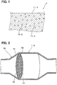
- a composite heat storage material 1 is made by mixing a heat storage material 2 and an inorganic material 3 different from the heat storage material 2.
- the heat storage material 2 is made of a strongly correlated electron material that stores and dissipates heat via solid-solid phase transition.
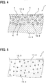
- the composite heat storage material 1 of the present embodiment is used as a material of a honeycomb structure 5 that purifies an exhaust gas generated in an engine of a vehicle.
- the honeycomb structure 5 is disposed in an exhaust gas pipe 55 in which the exhaust gas flows.
- the honeycomb structure 5 has an approximately circular column shape, and includes multiple cell walls 51 and multiple cell holes 52 penetrating the honeycomb structure 5 in an axial direction.
- the cell hole 52 is defined by the cell wall 51.
- the composite heat storage material 1 includes a primary member 11 that is the inorganic material 3 made of ceramic, and a dispersion member 12 that is the heat storage material 2.
- the heat storage material 2 is mixed and dispersed in the inorganic material 3.
- a ceramic such as Al 2 O 3 (aluminum oxide), AIN (aluminum nitride), or Si 3 N 4 (silicon nitride) is used as the inorganic material of the primary member 11.
- the heat storage material 2 that is the dispersion member 12 is mixed and dispersed in a whole of the inorganic material 3 approximately uniformly.
- the heat storage material 2 is made of VO 2 (vanadium dioxide) that is a strongly correlated electron material storing and dissipating heat via solid-solid phase transition, and the heat storage material 2 has a particulate shape that has an approximately sphere shape with approximately 10 mm diameter.
- VO 2 is an oxide of a transition metal including V (vanadium) that is a transition metal, and a phase transition temperature of VO 2 is approximately 68 °C.
- VO 2 is a metal-insulator transition material.
- VO 2 is in metal phase at or above the phase transition temperature and stores heat, and VO 2 is in insulation phase at or below the phase transition temperature and dissipates heat.
- the strongly correlated electron material that stores and dissipates heat via solid-solid phase transition stores and dissipates heat by using a phase transition enthalpy generated by transformation of a crystal structure via solid-solid phase transition.
- spin and orbital ordering also occurs, and heat storage and heat dissipation occur by using an enthalpy change caused by the spin and orbital ordering.
- a vanadium oxide such as VO 2 or V 2 O 3 , or NaNiO 2 , PrBaCo 2 O 55 , DyBaCo 2 O 5.5 , LiMn 2 O 4 , HoBaFe 2 O 5 , DyBaFe 2 O 5 , GdBaFe 2 O 5 , EuBaFe 2 O 5 , SmBaFe 2 O 5 , TbBaFe 2 O 5 or LiRh 2 O 4 can be used as the strongly correlated electron material that stores and dissipates heat via solid-solid phase transition.
- the vanadium oxide may be doped with W, Nb, Ta or Mo.
- the composite heat storage material 1 is made by mixing and dispersing the heat storage material 2 in the inorganic material 3, the inorganic material 3 works as a reinforcement material of the heat storage material 2, and accordingly a strength of the composite heat storage material 1 can be improved. Therefore, the composite heat storage material 1 that is capable of storing and dissipating heat at a desired temperature and has a desired strength can be obtained.
- the desired temperature for storing and dissipating heat and a desired heat storage amount can be obtained by adjusting a material and a ratio of the heat storage material 2.
- the desired strength can be obtained by adjusting a material and a ratio of the inorganic material 3.
- the inorganic material 3 is used as the primary member 11, and the heat storage material 2 is used as the dispersion member 12.
- the heat storage material 2 is mixed and dispersed in the inorganic material 3.
- the inorganic material 3 that is the primary member 11 can be selected without sacrificing a desired heat storage property of the composite heat storage material 1, the desired strength of the composite heat storage material 1 can be easily obtained. Accordingly, the composite heat storage material 1 can have a strength enough to form a variety of structures.
- the heat storage material 2 is made of the metal-insulator transition material that changes phases between a metal phase and an insulator phase.
- the metal-insulator transition material has a phase transition enthalpy larger than that of a typical solid-solid phase transition material. Accordingly, a heat storage amount of the heat storage material 2 can be increased.
- the composite heat storage material 1 having desired heat storage property and desired strength can be provided according to the present embodiment.
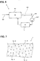
- a composite heat storage material 1 of the first embodiment configurations of a composite heat storage material 1 of the first embodiment are partially changed, as shown in FIG. 4 .
- a heat storage material 2 is mixed and dispersed in a ceramic that is an inorganic material 3.
- the heat storage member 2 is disposed near a surface of a honeycomb structure 5.
- an air space 4 is provided in the inorganic material 3 and a part of the heat storage material 2.
- the heat storage material 2 since the heat storage material 2 is dispersed so as to be located near the surface of the honeycomb structure 5, the heat storage material 2 is capable of storing and dissipating heat quickly. Accordingly, the heat can be effectively stored in the heat storage material 2, and an amount of heat dissipated from the heat storage material 2 per time can be increased.
- the air space 4 may be provided in at least one of the inorganic material 3 and the heat storage material 2.
- the air space 4 may be provided in the inorganic material 3, and the air space 4 may not be provided in the heat storage material 2.
- the air space 4 may be provided in the heat storage material 2, and the air space 4 may not be provided in the inorganic material 3.
- same effects as the first embodiment can be obtained.
- the composite heat storage material 1 is used as a material of the honeycomb structure 5 used in a vehicle.
- the composite heat storage material 1 can be used for various purposes. For example, specifically, when the inorganic material 3 is used as diatomaceous earth used for a wall or the like of a building, and when the heat storage material 2 is mixed and dispersed in the inorganic material 3, the composite heat storage material 1 for building can be obtained. In this case, an amount of energy for air conditioning of the building can be reduced.
- asphalt used for road is used as the inorganic material 3
- the composite heat storage material 1 for road can be obtained. In this case, since the heat storage material 2 dissipates heat during a low temperature, a road surface freezing can be prevented.
- the inorganic material 3 includes various inorganic substances such as metal, ceramic, and carbon material.
- the carbon material may be carbon nanotube, fullerene, graphene, graphite or the like.
- a composite heat storage material 1 (HS) of the first embodiment is changed.
- the composite heat storage material 1 is used in a heat storage system 6 which stores heat by using exhaust heat of an internal combustion engine (EG) 61 that is one of a driving source for travelling of a hybrid vehicle.
- EG internal combustion engine
- the heat storage system 6 is configured to transfer heat of the internal combustion engine 61 to the composite heat storage material 1 through a cooling water, and the heat storage system 6 is configured to store the heat in the composite heat storage material 1.
- the internal combustion engine 61 converts a thermal energy generated by combusting a fuel 62 to a driving energy. A part of the thermal energy is discharged to an exhaust gas pipe as an exhaust heat along with an exhaust gas 63 of the internal combustion engine.
- the internal combustion engine 61 and the composite heat storage material 1 are connected to each other by a cooling water passage 64 that forms a closed circuit between the internal combustion engine 61 and the composite heat storage material 1.
- a pump 641 circulating a cooling water in the cooling water passage 64 is provided in the cooling water passage 64.
- the cooling water in the cooling water passage 64 flows from a cooling water outlet of the internal combustion engine to a cooling water inlet of the internal combustion engine via a heat storage portion.
- the cooling water passage 64 is arranged so as to perform a heat exchange between the cooling water and the exhaust gas 63 flowing in the exhaust gas pipe.
- the cooling water passage 64 is arranged so as to perform a heat exchange between the cooling water and the composite heat storage material 1.
- the cooling water is heated to high temperature due to the heat exchange between the internal combustion engine 61 or the exhaust gas 63 and the cooling water.
- the heat can be stored in the composite heat storage material 1 by the heat exchange between the composite heat storage material 1 and the cooling water heated to the high temperature.
- the heat stored in the composite heat storage material 1 can be used for heating an conditioning air, for example.
- the composite heat storage material 1 of the present embodiment includes the primary member 11 made of heat storage material 2 that is the strongly correlated electron material heating and dissipating heat via solid-solid phase transition, and the dispersion member 12 made of inorganic material 3.
- the heat storage material 2 is made of VO 2 .
- the inorganic material 3 used as the dispersion member 12 is made of metal having a high thermal conductivity such as Al or Cu. Since the metal having a high thermal conductivity is dispersed in the composite heat storage material 1, a thermal conductivity of the composite heat storage material 1 can be improved, and accordingly a heat storage property and a heat dissipation property of the composite heat storage material 1 can be improved.
- the heat storage material 2 is used as the primary member 11, and since the inorganic material 3 is used as the dispersion member 12, characteristics of the inorganic material 3 can be added to the heat storage material 2. For example, when the inorganic material 3 having a high thermal conductivity is mixed and dispersed in the heat storage material 2, the composite heat storage material 1 superior in heat storage property can be obtained. When the inorganic material 3 superior in strength is mixed and dispersed in the heat storage material 2, the composite heat storage material 1 superior in strength can be obtained.
- a heat storage material 2 that is a primary member 11 is made of VO 2 .
- An inorganic material 3 that is a dispersion member 12 is made of a strongly correlated electron material storing and dissipating heat via solid-solid phase transition.
- the dispersion member 12 is made of V 2 O 3 (vanadium trioxide).
- the V 2 O 3 is a transition metal oxide including V that is a transition metal.
- a phase transition temperature of V 2 O 3 is -119 °C.
- V 2 O 3 is a metal-insulator transition material that is in solid phase at or above the transition temperature and stores heat.
- V 2 O 3 is a metal-insulator transition material that is in insulator phase at or below the phase transition temperature and dissipates heat.
- both the inorganic material 3 and the heat storage material 2 are made of strongly correlated electron material, an amount of heat storage in the composite heat storage material 1 can be increased.
- the inorganic material 3 and the heat storage material 2 are made of strongly correlated electron materials having phase transition temperature different from each other. Accordingly, a temperature range where the inorganic material 3 stores and dissipates heat is different from a temperature range where the heat storage material 2 stores and dissipates heat. Therefore, the composite heat storage material 1 is capable of storing and dissipating heat in a broad temperature range. The same effects as the first embodiment can be obtained by the present embodiment.
Landscapes
- Chemical & Material Sciences (AREA)
- Engineering & Computer Science (AREA)
- Chemical Kinetics & Catalysis (AREA)
- Combustion & Propulsion (AREA)
- Materials Engineering (AREA)
- Organic Chemistry (AREA)
- Thermal Sciences (AREA)
- Physics & Mathematics (AREA)
- General Engineering & Computer Science (AREA)
- Mechanical Engineering (AREA)
- Health & Medical Sciences (AREA)
- Toxicology (AREA)
- Biomedical Technology (AREA)
- Environmental & Geological Engineering (AREA)
- Analytical Chemistry (AREA)
- General Chemical & Material Sciences (AREA)
- Oil, Petroleum & Natural Gas (AREA)
- Laminated Bodies (AREA)
- Compositions Of Macromolecular Compounds (AREA)
- Cooling Or The Like Of Electrical Apparatus (AREA)
Claims (4)
- Matériau de stockage de chaleur composite (1) pour une structure en nid d'abeille (5), le matériau de stockage de chaleur composite comprenant :un matériau de stockage de chaleur (2) fait d'un matériau à électrons fortement corrélés qui stocke et dissipe la chaleur via une transition de phases solide-solide ; etun matériau inorganique (3) fait d'un métal qui est différent du métal du matériau de stockage de chaleur (2),dans lequelle matériau inorganique (3) est utilisé en tant qu'élément primaire (11),le matériau de stockage de chaleur (2) est utilisé en tant qu'élément de dispersion (12), etle matériau de stockage de chaleur (2) est mélangé et dispersé dans le matériau inorganique (3),dans lequel le matériau de stockage de chaleur (2) est dispersé de façon à être situé près d'une surface de la structure en nid d'abeille. (5)
- Matériau de stockage de chaleur composite (1) selon la revendication 1, dans lequel le matériau de stockage de chaleur (2) est fait en un matériau qui présente une transition métal-isolant.
- Matériau de stockage de chaleur composite (1) selon l'une quelconque des revendications 1 et 2, dans lequel un espace d'air (4) est disposé dans le matériau inorganique (3).
- Matériau de stockage de chaleur composite (1) selon l'une quelconque des revendications 1 à 3, dans lequel un espace d'air (4) est disposé dans le matériau de stockage de chaleur (2).
Applications Claiming Priority (2)
| Application Number | Priority Date | Filing Date | Title |
|---|---|---|---|
| JP2014214973A JP2016079351A (ja) | 2014-10-22 | 2014-10-22 | 複合蓄熱材 |
| PCT/JP2015/005113 WO2016063478A1 (fr) | 2014-10-22 | 2015-10-08 | Matériau de stockage de chaleur composite |
Publications (3)
| Publication Number | Publication Date |
|---|---|
| EP3211054A1 EP3211054A1 (fr) | 2017-08-30 |
| EP3211054A4 EP3211054A4 (fr) | 2017-10-25 |
| EP3211054B1 true EP3211054B1 (fr) | 2021-08-04 |
Family
ID=55760539
Family Applications (1)
| Application Number | Title | Priority Date | Filing Date |
|---|---|---|---|
| EP15852856.2A Active EP3211054B1 (fr) | 2014-10-22 | 2015-10-08 | Matériau de stockage de chaleur composite |
Country Status (5)
| Country | Link |
|---|---|
| US (1) | US10155895B2 (fr) |
| EP (1) | EP3211054B1 (fr) |
| JP (1) | JP2016079351A (fr) |
| CN (1) | CN107075351A (fr) |
| WO (1) | WO2016063478A1 (fr) |
Families Citing this family (5)
| Publication number | Priority date | Publication date | Assignee | Title |
|---|---|---|---|---|
| WO2017179454A1 (fr) * | 2016-04-12 | 2017-10-19 | 株式会社村田製作所 | Composition contenant des particules de céramique |
| JPWO2018174210A1 (ja) * | 2017-03-24 | 2020-01-23 | 国立大学法人 東京大学 | 蓄放熱性酸化チタンを含有する樹脂組成物とそれより得られるヒートストレージ材 |
| JP2019192882A (ja) * | 2018-04-27 | 2019-10-31 | 株式会社東芝 | 半導体モジュール |
| CA3137502A1 (fr) * | 2019-04-26 | 2020-10-29 | Energy Systems Management Limited | Accumulateur calorique |
| CN115605558B (zh) | 2020-05-14 | 2026-03-13 | 国立研究开发法人产业技术综合研究所 | 调节了热传导率的固体蓄热材料和复合体 |
Family Cites Families (32)
| Publication number | Priority date | Publication date | Assignee | Title |
|---|---|---|---|---|
| US4873038A (en) * | 1987-07-06 | 1989-10-10 | Lanxide Technology Comapny, Lp | Method for producing ceramic/metal heat storage media, and to the product thereof |
| US5178875A (en) * | 1991-01-14 | 1993-01-12 | The Board Of Regents, The University Of Texas System | Liposomal-polyene preliposomal powder and method for its preparation |
| JPH05320629A (ja) * | 1992-05-15 | 1993-12-03 | Matsushita Electric Works Ltd | 潜熱蓄熱体 |
| US5413649A (en) * | 1993-07-29 | 1995-05-09 | Massachusetts Institute Of Technology | Method for enhancing superplasticity in composites |
| US5641424A (en) * | 1995-07-10 | 1997-06-24 | Xerox Corporation | Magnetic refrigerant compositions and processes for making and using |
| US6200631B1 (en) * | 1997-10-27 | 2001-03-13 | Praxair Technology, Inc. | Method for producing corrosion resistant refractories |
| DE10018938A1 (de) * | 2000-04-17 | 2001-10-18 | Merck Patent Gmbh | Speichermedien für Latentwärmespeicher |
| JP4846210B2 (ja) * | 2003-10-09 | 2011-12-28 | エスケー化研株式会社 | 蓄熱体 |
| JP2005268578A (ja) * | 2004-03-19 | 2005-09-29 | Toudai Tlo Ltd | サーミスタ素子 |
| JP4790305B2 (ja) * | 2004-05-12 | 2011-10-12 | エスケー化研株式会社 | マイクロカプセル及びその製造方法 |
| JP2009024086A (ja) * | 2007-07-19 | 2009-02-05 | Harima Chem Inc | 担持型固形蓄熱材の製造方法 |
| JP5688725B2 (ja) * | 2009-01-14 | 2015-03-25 | 独立行政法人理化学研究所 | 蓄熱材 |
| KR20110052225A (ko) * | 2009-11-12 | 2011-05-18 | 삼성전자주식회사 | 나노복합체형 열전재료 및 이를 포함하는 열전소자와 열전모듈 |
| JP2011127832A (ja) * | 2009-12-17 | 2011-06-30 | Teijin Ltd | 熱交換性能を向上させた蓄熱装置 |
| JP5619435B2 (ja) * | 2010-02-26 | 2014-11-05 | 三菱重工業株式会社 | 蓄熱部材及びその製造方法 |
| JP5464168B2 (ja) | 2010-06-04 | 2014-04-09 | 株式会社デンソー | 電源装置 |
| US20120042687A1 (en) | 2010-08-23 | 2012-02-23 | Showa Denko K.K. | Evaporator with cool storage function |
| JP2012102264A (ja) * | 2010-11-11 | 2012-05-31 | Kitagawa Ind Co Ltd | 熱対策部材 |
| WO2012176708A1 (fr) * | 2011-06-21 | 2012-12-27 | シャープ株式会社 | Élément de stockage de chaleur et contenant de stockage de chaleur |
| JP2013013844A (ja) * | 2011-07-01 | 2013-01-24 | Miki Riken Kogyo Kk | 機能性微粒子及びその製造方法 |
| CN103014819A (zh) * | 2011-09-27 | 2013-04-03 | 肖云捷 | 一种用于机械配件的耐磨复合层材料及制造方法和设备 |
| JP2013129828A (ja) | 2011-11-22 | 2013-07-04 | Jsr Corp | 蓄熱材及び蓄熱用装置 |
| US8840803B2 (en) * | 2012-02-02 | 2014-09-23 | Baker Hughes Incorporated | Thermally conductive nanocomposition and method of making the same |
| JP2013200073A (ja) | 2012-03-26 | 2013-10-03 | Keihin Thermal Technology Corp | 蓄冷機能付きエバポレータ |
| JP5923619B2 (ja) | 2012-10-29 | 2016-05-24 | 株式会社日立製作所 | 蓄熱システム、発電システム |
| JP2014091759A (ja) * | 2012-11-01 | 2014-05-19 | Riso Kagaku Corp | 潜熱蓄熱材料及びその製造方法 |
| JP5935726B2 (ja) * | 2013-03-07 | 2016-06-15 | マツダ株式会社 | 脱臭処理装置 |
| JP5991234B2 (ja) * | 2013-03-07 | 2016-09-14 | マツダ株式会社 | 脱臭処理装置 |
| JP2014196884A (ja) * | 2013-03-29 | 2014-10-16 | ダイハツ工業株式会社 | 潜熱蓄熱装置 |
| CN103289655B (zh) * | 2013-07-03 | 2016-03-02 | 西北大学 | 膨胀石墨复合蓄热材料及其制备方法和应用 |
| CN105264039B (zh) * | 2013-12-11 | 2019-05-07 | 富士高分子工业株式会社 | 蓄热性组合物 |
| US10030186B2 (en) * | 2016-08-29 | 2018-07-24 | Quantum Technology Group Limited | Heat transfer medium |
-
2014
- 2014-10-22 JP JP2014214973A patent/JP2016079351A/ja active Pending
-
2015
- 2015-10-08 EP EP15852856.2A patent/EP3211054B1/fr active Active
- 2015-10-08 US US15/510,805 patent/US10155895B2/en active Active
- 2015-10-08 CN CN201580056946.2A patent/CN107075351A/zh active Pending
- 2015-10-08 WO PCT/JP2015/005113 patent/WO2016063478A1/fr not_active Ceased
Non-Patent Citations (1)
| Title |
|---|
| None * |
Also Published As
| Publication number | Publication date |
|---|---|
| CN107075351A (zh) | 2017-08-18 |
| EP3211054A4 (fr) | 2017-10-25 |
| JP2016079351A (ja) | 2016-05-16 |
| US20170298262A1 (en) | 2017-10-19 |
| EP3211054A1 (fr) | 2017-08-30 |
| WO2016063478A1 (fr) | 2016-04-28 |
| US10155895B2 (en) | 2018-12-18 |
Similar Documents
| Publication | Publication Date | Title |
|---|---|---|
| EP3211054B1 (fr) | Matériau de stockage de chaleur composite | |
| Wang et al. | Functional carbon springs enabled dynamic tunable microwave absorption and thermal insulation | |
| Tan et al. | Synergistic texturing and Bi/Sb‐Te antisite doping secure high thermoelectric performance in Bi0. 5Sb1. 5Te3‐based thin films | |
| Chen et al. | Multiple schottky contacts motivated via defects to tune the response ability of electromagnetic waves | |
| Wu et al. | Lattice strain enhances thermoelectric properties in Sb2Te3/Te heterostructure | |
| Menni et al. | Advances of nanofluids in heat exchangers—a review | |
| Huang et al. | Manipulating orientation of silicon carbide nanowire in polymer composites to achieve high thermal conductivity | |
| Hwang et al. | Epoxy-based thermally conductive adhesives with effective alumina and boron nitride for superconducting magnet | |
| Luo et al. | Modulation of dielectric behavior in ceramic‐based materials for integrated electromagnetic waves absorption and thermal conduction | |
| Tarigonda et al. | Experimental investigation on the heat pipe using Al2O3 and CuO hybrid nanofluid | |
| Kundalwal et al. | Effective thermal conductivities of a novel fuzzy carbon fiber heat exchanger containing wavy carbon nanotubes | |
| Silveira et al. | Temperature‐dependent Raman spectroscopy study in MoO3 nanoribbons | |
| Shukla et al. | Thermal performance of heat pipe with suspended nano-particles | |
| Wang et al. | Physical vapor transport growth of antiferromagnetic CrCl3 flakes down to monolayer thickness | |
| Dai et al. | An Ultra‐Broadband Electromagnetic Wave Absorbing ZrB2‐Based Ceramic Composite Inspired by Barbule of Peacock | |
| Glas et al. | Calculation of the temperature profile in nanowhiskers growing on a hot substrate | |
| Chen et al. | High-temperature driven inter-valley carrier transfer and significant fluorescence enhancement in multilayer WS 2 | |
| Feng et al. | Enhanced Thermal Conductivity of Single‐Walled Carbon Nanotube with Axial Tensile Strain Enabled by Boron Nitride Nanotube Anchoring | |
| Xu et al. | Magnetic and Magnetocaloric Properties in Sr2 RE TaO6 (RE= Dy, Ho, and Er) Compounds | |
| US11333453B2 (en) | Vehicle heat exchanger and vehicle front structure having the same | |
| WO2016063479A1 (fr) | Matériau de stockage de chaleur stratifié | |
| Sun et al. | Large negative electrocaloric response induced by nanoscale phase transition in (Bi, Na) TiO3-based thin films | |
| Salehin et al. | Utilization of nanofluid in various clean energy and energy efficiency applications | |
| Aravindkumar et al. | Computational and numerical analysis of radiator with different tube structures and nano fluid as coolant | |
| Zianni | The annealed-nanograin phase: A route to simultaneous increase of the conductivity and the Seebeck coefficient and high thermoelectric performance |
Legal Events
| Date | Code | Title | Description |
|---|---|---|---|
| STAA | Information on the status of an ep patent application or granted ep patent |
Free format text: STATUS: THE INTERNATIONAL PUBLICATION HAS BEEN MADE |
|
| PUAI | Public reference made under article 153(3) epc to a published international application that has entered the european phase |
Free format text: ORIGINAL CODE: 0009012 |
|
| STAA | Information on the status of an ep patent application or granted ep patent |
Free format text: STATUS: REQUEST FOR EXAMINATION WAS MADE |
|
| 17P | Request for examination filed |
Effective date: 20170315 |
|
| AK | Designated contracting states |
Kind code of ref document: A1 Designated state(s): AL AT BE BG CH CY CZ DE DK EE ES FI FR GB GR HR HU IE IS IT LI LT LU LV MC MK MT NL NO PL PT RO RS SE SI SK SM TR |
|
| AX | Request for extension of the european patent |
Extension state: BA ME |
|
| A4 | Supplementary search report drawn up and despatched |
Effective date: 20170922 |
|
| RIC1 | Information provided on ipc code assigned before grant |
Ipc: C09K 5/02 20060101AFI20170918BHEP |
|
| DAV | Request for validation of the european patent (deleted) | ||
| DAX | Request for extension of the european patent (deleted) | ||
| STAA | Information on the status of an ep patent application or granted ep patent |
Free format text: STATUS: EXAMINATION IS IN PROGRESS |
|
| 17Q | First examination report despatched |
Effective date: 20180822 |
|
| REG | Reference to a national code |
Ref country code: DE Ref legal event code: R079 Ref document number: 602015072037 Country of ref document: DE Free format text: PREVIOUS MAIN CLASS: C09K0005020000 Ipc: C09K0005140000 |
|
| RIC1 | Information provided on ipc code assigned before grant |
Ipc: C09K 5/14 20060101AFI20210114BHEP |
|
| GRAP | Despatch of communication of intention to grant a patent |
Free format text: ORIGINAL CODE: EPIDOSNIGR1 |
|
| STAA | Information on the status of an ep patent application or granted ep patent |
Free format text: STATUS: GRANT OF PATENT IS INTENDED |
|
| INTG | Intention to grant announced |
Effective date: 20210222 |
|
| GRAS | Grant fee paid |
Free format text: ORIGINAL CODE: EPIDOSNIGR3 |
|
| GRAA | (expected) grant |
Free format text: ORIGINAL CODE: 0009210 |
|
| STAA | Information on the status of an ep patent application or granted ep patent |
Free format text: STATUS: THE PATENT HAS BEEN GRANTED |
|
| AK | Designated contracting states |
Kind code of ref document: B1 Designated state(s): AL AT BE BG CH CY CZ DE DK EE ES FI FR GB GR HR HU IE IS IT LI LT LU LV MC MK MT NL NO PL PT RO RS SE SI SK SM TR |
|
| RAP3 | Party data changed (applicant data changed or rights of an application transferred) |
Owner name: DENSO CORPORATION |
|
| REG | Reference to a national code |
Ref country code: GB Ref legal event code: FG4D |
|
| RIN1 | Information on inventor provided before grant (corrected) |
Inventor name: KASAMATSU, SHINYA Inventor name: OKUNO, EIICHI Inventor name: KONO, YASUSHI Inventor name: FUSE, TAKUYA |
|
| REG | Reference to a national code |
Ref country code: AT Ref legal event code: REF Ref document number: 1416999 Country of ref document: AT Kind code of ref document: T Effective date: 20210815 |
|
| REG | Reference to a national code |
Ref country code: CH Ref legal event code: EP |
|
| REG | Reference to a national code |
Ref country code: DE Ref legal event code: R096 Ref document number: 602015072037 Country of ref document: DE |
|
| REG | Reference to a national code |
Ref country code: IE Ref legal event code: FG4D |
|
| REG | Reference to a national code |
Ref country code: LT Ref legal event code: MG9D |
|
| REG | Reference to a national code |
Ref country code: NL Ref legal event code: MP Effective date: 20210804 |
|
| REG | Reference to a national code |
Ref country code: AT Ref legal event code: MK05 Ref document number: 1416999 Country of ref document: AT Kind code of ref document: T Effective date: 20210804 |
|
| PG25 | Lapsed in a contracting state [announced via postgrant information from national office to epo] |
Ref country code: LT Free format text: LAPSE BECAUSE OF FAILURE TO SUBMIT A TRANSLATION OF THE DESCRIPTION OR TO PAY THE FEE WITHIN THE PRESCRIBED TIME-LIMIT Effective date: 20210804 Ref country code: BG Free format text: LAPSE BECAUSE OF FAILURE TO SUBMIT A TRANSLATION OF THE DESCRIPTION OR TO PAY THE FEE WITHIN THE PRESCRIBED TIME-LIMIT Effective date: 20211104 Ref country code: AT Free format text: LAPSE BECAUSE OF FAILURE TO SUBMIT A TRANSLATION OF THE DESCRIPTION OR TO PAY THE FEE WITHIN THE PRESCRIBED TIME-LIMIT Effective date: 20210804 Ref country code: PT Free format text: LAPSE BECAUSE OF FAILURE TO SUBMIT A TRANSLATION OF THE DESCRIPTION OR TO PAY THE FEE WITHIN THE PRESCRIBED TIME-LIMIT Effective date: 20211206 Ref country code: NO Free format text: LAPSE BECAUSE OF FAILURE TO SUBMIT A TRANSLATION OF THE DESCRIPTION OR TO PAY THE FEE WITHIN THE PRESCRIBED TIME-LIMIT Effective date: 20211104 Ref country code: FI Free format text: LAPSE BECAUSE OF FAILURE TO SUBMIT A TRANSLATION OF THE DESCRIPTION OR TO PAY THE FEE WITHIN THE PRESCRIBED TIME-LIMIT Effective date: 20210804 Ref country code: ES Free format text: LAPSE BECAUSE OF FAILURE TO SUBMIT A TRANSLATION OF THE DESCRIPTION OR TO PAY THE FEE WITHIN THE PRESCRIBED TIME-LIMIT Effective date: 20210804 Ref country code: HR Free format text: LAPSE BECAUSE OF FAILURE TO SUBMIT A TRANSLATION OF THE DESCRIPTION OR TO PAY THE FEE WITHIN THE PRESCRIBED TIME-LIMIT Effective date: 20210804 Ref country code: RS Free format text: LAPSE BECAUSE OF FAILURE TO SUBMIT A TRANSLATION OF THE DESCRIPTION OR TO PAY THE FEE WITHIN THE PRESCRIBED TIME-LIMIT Effective date: 20210804 Ref country code: SE Free format text: LAPSE BECAUSE OF FAILURE TO SUBMIT A TRANSLATION OF THE DESCRIPTION OR TO PAY THE FEE WITHIN THE PRESCRIBED TIME-LIMIT Effective date: 20210804 |
|
| PG25 | Lapsed in a contracting state [announced via postgrant information from national office to epo] |
Ref country code: PL Free format text: LAPSE BECAUSE OF FAILURE TO SUBMIT A TRANSLATION OF THE DESCRIPTION OR TO PAY THE FEE WITHIN THE PRESCRIBED TIME-LIMIT Effective date: 20210804 Ref country code: LV Free format text: LAPSE BECAUSE OF FAILURE TO SUBMIT A TRANSLATION OF THE DESCRIPTION OR TO PAY THE FEE WITHIN THE PRESCRIBED TIME-LIMIT Effective date: 20210804 Ref country code: GR Free format text: LAPSE BECAUSE OF FAILURE TO SUBMIT A TRANSLATION OF THE DESCRIPTION OR TO PAY THE FEE WITHIN THE PRESCRIBED TIME-LIMIT Effective date: 20211105 |
|
| PG25 | Lapsed in a contracting state [announced via postgrant information from national office to epo] |
Ref country code: NL Free format text: LAPSE BECAUSE OF FAILURE TO SUBMIT A TRANSLATION OF THE DESCRIPTION OR TO PAY THE FEE WITHIN THE PRESCRIBED TIME-LIMIT Effective date: 20210804 |
|
| PG25 | Lapsed in a contracting state [announced via postgrant information from national office to epo] |
Ref country code: DK Free format text: LAPSE BECAUSE OF FAILURE TO SUBMIT A TRANSLATION OF THE DESCRIPTION OR TO PAY THE FEE WITHIN THE PRESCRIBED TIME-LIMIT Effective date: 20210804 |
|
| REG | Reference to a national code |
Ref country code: DE Ref legal event code: R097 Ref document number: 602015072037 Country of ref document: DE |
|
| REG | Reference to a national code |
Ref country code: CH Ref legal event code: PL |
|
| PG25 | Lapsed in a contracting state [announced via postgrant information from national office to epo] |
Ref country code: SM Free format text: LAPSE BECAUSE OF FAILURE TO SUBMIT A TRANSLATION OF THE DESCRIPTION OR TO PAY THE FEE WITHIN THE PRESCRIBED TIME-LIMIT Effective date: 20210804 Ref country code: SK Free format text: LAPSE BECAUSE OF FAILURE TO SUBMIT A TRANSLATION OF THE DESCRIPTION OR TO PAY THE FEE WITHIN THE PRESCRIBED TIME-LIMIT Effective date: 20210804 Ref country code: RO Free format text: LAPSE BECAUSE OF FAILURE TO SUBMIT A TRANSLATION OF THE DESCRIPTION OR TO PAY THE FEE WITHIN THE PRESCRIBED TIME-LIMIT Effective date: 20210804 Ref country code: EE Free format text: LAPSE BECAUSE OF FAILURE TO SUBMIT A TRANSLATION OF THE DESCRIPTION OR TO PAY THE FEE WITHIN THE PRESCRIBED TIME-LIMIT Effective date: 20210804 Ref country code: CZ Free format text: LAPSE BECAUSE OF FAILURE TO SUBMIT A TRANSLATION OF THE DESCRIPTION OR TO PAY THE FEE WITHIN THE PRESCRIBED TIME-LIMIT Effective date: 20210804 Ref country code: AL Free format text: LAPSE BECAUSE OF FAILURE TO SUBMIT A TRANSLATION OF THE DESCRIPTION OR TO PAY THE FEE WITHIN THE PRESCRIBED TIME-LIMIT Effective date: 20210804 |
|
| PLBE | No opposition filed within time limit |
Free format text: ORIGINAL CODE: 0009261 |
|
| STAA | Information on the status of an ep patent application or granted ep patent |
Free format text: STATUS: NO OPPOSITION FILED WITHIN TIME LIMIT |
|
| REG | Reference to a national code |
Ref country code: BE Ref legal event code: MM Effective date: 20211031 |
|
| PG25 | Lapsed in a contracting state [announced via postgrant information from national office to epo] |
Ref country code: MC Free format text: LAPSE BECAUSE OF FAILURE TO SUBMIT A TRANSLATION OF THE DESCRIPTION OR TO PAY THE FEE WITHIN THE PRESCRIBED TIME-LIMIT Effective date: 20210804 |
|
| 26N | No opposition filed |
Effective date: 20220506 |
|
| PG25 | Lapsed in a contracting state [announced via postgrant information from national office to epo] |
Ref country code: LU Free format text: LAPSE BECAUSE OF NON-PAYMENT OF DUE FEES Effective date: 20211008 Ref country code: IT Free format text: LAPSE BECAUSE OF FAILURE TO SUBMIT A TRANSLATION OF THE DESCRIPTION OR TO PAY THE FEE WITHIN THE PRESCRIBED TIME-LIMIT Effective date: 20210804 Ref country code: BE Free format text: LAPSE BECAUSE OF NON-PAYMENT OF DUE FEES Effective date: 20211031 |
|
| PG25 | Lapsed in a contracting state [announced via postgrant information from national office to epo] |
Ref country code: SI Free format text: LAPSE BECAUSE OF FAILURE TO SUBMIT A TRANSLATION OF THE DESCRIPTION OR TO PAY THE FEE WITHIN THE PRESCRIBED TIME-LIMIT Effective date: 20210804 Ref country code: LI Free format text: LAPSE BECAUSE OF NON-PAYMENT OF DUE FEES Effective date: 20211031 Ref country code: CH Free format text: LAPSE BECAUSE OF NON-PAYMENT OF DUE FEES Effective date: 20211031 |
|
| PG25 | Lapsed in a contracting state [announced via postgrant information from national office to epo] |
Ref country code: IE Free format text: LAPSE BECAUSE OF NON-PAYMENT OF DUE FEES Effective date: 20211008 |
|
| PG25 | Lapsed in a contracting state [announced via postgrant information from national office to epo] |
Ref country code: HU Free format text: LAPSE BECAUSE OF FAILURE TO SUBMIT A TRANSLATION OF THE DESCRIPTION OR TO PAY THE FEE WITHIN THE PRESCRIBED TIME-LIMIT; INVALID AB INITIO Effective date: 20151008 |
|
| PG25 | Lapsed in a contracting state [announced via postgrant information from national office to epo] |
Ref country code: CY Free format text: LAPSE BECAUSE OF FAILURE TO SUBMIT A TRANSLATION OF THE DESCRIPTION OR TO PAY THE FEE WITHIN THE PRESCRIBED TIME-LIMIT Effective date: 20210804 |
|
| PG25 | Lapsed in a contracting state [announced via postgrant information from national office to epo] |
Ref country code: MK Free format text: LAPSE BECAUSE OF FAILURE TO SUBMIT A TRANSLATION OF THE DESCRIPTION OR TO PAY THE FEE WITHIN THE PRESCRIBED TIME-LIMIT Effective date: 20210804 |
|
| PG25 | Lapsed in a contracting state [announced via postgrant information from national office to epo] |
Ref country code: MT Free format text: LAPSE BECAUSE OF FAILURE TO SUBMIT A TRANSLATION OF THE DESCRIPTION OR TO PAY THE FEE WITHIN THE PRESCRIBED TIME-LIMIT Effective date: 20210804 |
|
| PG25 | Lapsed in a contracting state [announced via postgrant information from national office to epo] |
Ref country code: TR Free format text: LAPSE BECAUSE OF FAILURE TO SUBMIT A TRANSLATION OF THE DESCRIPTION OR TO PAY THE FEE WITHIN THE PRESCRIBED TIME-LIMIT Effective date: 20210804 |
|
| PGFP | Annual fee paid to national office [announced via postgrant information from national office to epo] |
Ref country code: DE Payment date: 20251021 Year of fee payment: 11 |
|
| PGFP | Annual fee paid to national office [announced via postgrant information from national office to epo] |
Ref country code: GB Payment date: 20251024 Year of fee payment: 11 |
|
| PGFP | Annual fee paid to national office [announced via postgrant information from national office to epo] |
Ref country code: FR Payment date: 20251030 Year of fee payment: 11 |