WO2012176708A1 - Élément de stockage de chaleur et contenant de stockage de chaleur - Google Patents
Élément de stockage de chaleur et contenant de stockage de chaleur Download PDFInfo
- Publication number
- WO2012176708A1 WO2012176708A1 PCT/JP2012/065369 JP2012065369W WO2012176708A1 WO 2012176708 A1 WO2012176708 A1 WO 2012176708A1 JP 2012065369 W JP2012065369 W JP 2012065369W WO 2012176708 A1 WO2012176708 A1 WO 2012176708A1
- Authority
- WO
- WIPO (PCT)
- Prior art keywords
- heat storage
- latent heat
- phase change
- volume
- storage member
- Prior art date
- Legal status (The legal status is an assumption and is not a legal conclusion. Google has not performed a legal analysis and makes no representation as to the accuracy of the status listed.)
- Ceased
Links
Images




Classifications
-
- C—CHEMISTRY; METALLURGY
- C09—DYES; PAINTS; POLISHES; NATURAL RESINS; ADHESIVES; COMPOSITIONS NOT OTHERWISE PROVIDED FOR; APPLICATIONS OF MATERIALS NOT OTHERWISE PROVIDED FOR
- C09K—MATERIALS FOR MISCELLANEOUS APPLICATIONS, NOT PROVIDED FOR ELSEWHERE
- C09K5/00—Heat-transfer, heat-exchange or heat-storage materials, e.g. refrigerants; Materials for the production of heat or cold by chemical reactions other than by combustion
- C09K5/02—Materials undergoing a change of physical state when used
- C09K5/06—Materials undergoing a change of physical state when used the change of state being from liquid to solid or vice versa
- C09K5/063—Materials absorbing or liberating heat during crystallisation; Heat storage materials
-
- F—MECHANICAL ENGINEERING; LIGHTING; HEATING; WEAPONS; BLASTING
- F28—HEAT EXCHANGE IN GENERAL
- F28D—HEAT-EXCHANGE APPARATUS, NOT PROVIDED FOR IN ANOTHER SUBCLASS, IN WHICH THE HEAT-EXCHANGE MEDIA DO NOT COME INTO DIRECT CONTACT
- F28D20/00—Heat storage plants or apparatus in general; Regenerative heat-exchange apparatus not covered by groups F28D17/00 or F28D19/00
- F28D20/02—Heat storage plants or apparatus in general; Regenerative heat-exchange apparatus not covered by groups F28D17/00 or F28D19/00 using latent heat
-
- F—MECHANICAL ENGINEERING; LIGHTING; HEATING; WEAPONS; BLASTING
- F28—HEAT EXCHANGE IN GENERAL
- F28F—DETAILS OF HEAT-EXCHANGE AND HEAT-TRANSFER APPARATUS, OF GENERAL APPLICATION
- F28F2265/00—Safety or protection arrangements; Arrangements for preventing malfunction
- F28F2265/26—Safety or protection arrangements; Arrangements for preventing malfunction for allowing differential expansion between elements
-
- Y—GENERAL TAGGING OF NEW TECHNOLOGICAL DEVELOPMENTS; GENERAL TAGGING OF CROSS-SECTIONAL TECHNOLOGIES SPANNING OVER SEVERAL SECTIONS OF THE IPC; TECHNICAL SUBJECTS COVERED BY FORMER USPC CROSS-REFERENCE ART COLLECTIONS [XRACs] AND DIGESTS
- Y02—TECHNOLOGIES OR APPLICATIONS FOR MITIGATION OR ADAPTATION AGAINST CLIMATE CHANGE
- Y02E—REDUCTION OF GREENHOUSE GAS [GHG] EMISSIONS, RELATED TO ENERGY GENERATION, TRANSMISSION OR DISTRIBUTION
- Y02E60/00—Enabling technologies; Technologies with a potential or indirect contribution to GHG emissions mitigation
- Y02E60/14—Thermal energy storage
Definitions
- the present invention relates to a heat storage member and a heat storage container using a phase change material.
- Patent Document 1 discloses a heat storage unit including a sealed container in which a latent heat storage material and a filling gas are sealed.
- the hermetic container includes a heat storage material storage unit and a gas storage unit.
- the side wall of the gas storage part is formed in a telescopic bellows shape.
- the volume of the sealed container changes with the expansion and contraction of the side wall. Thereby, the airtight container can absorb the volume change accompanying the phase change of a latent heat storage material.
- An object of the present invention is to provide a heat storage member and a heat storage container having a high heat storage effect while suppressing deformation and mechanical breakage of the container due to volume change of the phase change material.
- the object is to provide a first phase change material whose volume shrinks due to a phase change when the temperature drops, a second phase change material whose volume expands due to a phase change when the temperature drops, the first phase change material, and This is achieved by a heat storage member comprising a container body that contains both of the second phase change materials.
- the phase change is a phase change from a liquid phase to a solid phase.
- the difference between the volume shrinkage before and after the phase change of the first phase change material and the volume expansion before and after the phase change of the second phase change material is the first phase. It is within ⁇ 5% of the sum of the volume of the change material before the phase change and the volume of the second phase change material before the phase change.
- the difference between the phase change temperature of the first phase change material and the phase change temperature of the second phase change material is within 7 ° C.
- the first phase change material includes paraffin.
- the second phase change material contains water or an aqueous salt solution.
- At least one of the first phase change material and the second phase change material contains a gelling agent.
- the heat storage member of the present invention is characterized by further comprising a partition plate provided at a boundary between the first phase change material and the second phase change material in the container.
- the present invention it is possible to realize a heat storage member and a heat storage container having a high heat storage effect while suppressing deformation and mechanical breakage of the container due to a volume change of the phase change material.
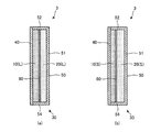
- FIGS. 1A and 1B show a schematic cross-sectional configuration of a heat storage member 1 according to the present embodiment.
- FIG. 1A and FIGS. 6A to 9A described later show a state in which the two kinds of latent heat storage materials 10 and 20 are both in the liquid phase (L)
- FIG. (B) of FIGS. 6 to 9 to be described later shows a state in which the two kinds of latent heat storage materials 10 and 20 are both solid phases (S).
- S solid phases
- the heat storage member 1 of the present embodiment includes both a first latent heat storage material 10, a second latent heat storage material 20, and latent heat storage materials 10 and 20. And a container body 30 for housing the container.
- the heat storage member 1 of this example has a plate shape (for example, a rectangular flat plate shape) as a whole.
- the latent heat storage materials 10 and 20 are stacked in the thickness direction of the heat storage member 1.
- the heat storage member 1 of this example is provided, for example, on the inner wall surface in the refrigerator.
- the heat storage member 1 is usually used in a predetermined operating temperature range and operating pressure range.
- the heat storage member 1 stores the cold by being cooled in the refrigerator, and when the operation of the refrigerator is stopped during a power failure or the like, the heat storage member 1 releases the cold and keeps the refrigerator in the refrigerator for a predetermined time.
- the operating temperature range of the heat storage member 1 includes the temperature range from the set temperature (internal temperature) of the refrigerator during operation to the ambient temperature (for example, room temperature) of the refrigerator installation location.
- the operating pressure of the heat storage member 1 is, for example, atmospheric pressure.
- Each of the latent heat storage materials 10 and 20 in the heat storage member 1 has a phase change temperature at which the phase change between the solid phase and the liquid phase (first type phase transition) occurs reversibly within the operating temperature range of the heat storage member 1. is doing.
- the latent heat storage materials 10 and 20 are in a liquid phase (L) as shown in FIG. 1A at a temperature higher than the phase change temperature (for example, room temperature), and lower than the phase change temperature (for example, during operation).
- the solid phase (S) is obtained as shown in FIG.
- the phase change temperature of the latent heat storage materials 10, 20 can be measured using a differential scanning calorimeter (DSC), a thermocouple, or the like.
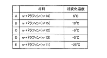
- FIG. 2 illustrates a material used as the latent heat storage material 10 that shrinks in volume when the phase changes from a liquid phase to a solid phase in the present embodiment.
- the latent heat storage material 10 of the present embodiment contains paraffin.
- Paraffin is a generic name for saturated chain hydrocarbons represented by the general formula C n H 2n + 2 .
- n-paraffin can be used not only alone but also as a mixture of two or more.
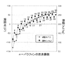
- FIG. 3 is a graph showing an example of the relationship between the number of carbon chains of n-paraffin, the freezing point (melting point), and the latent heat of fusion.
- the horizontal axis of the graph represents the number of carbon chains of n-paraffin (5 to 30), and the vertical axis represents the freezing point (° C.) or the latent heat of fusion (kJ / kg).
- the freezing point of n-paraffin increases as the number of carbon chains increases.
- the latent heat of fusion of n-paraffin is smaller when the number of carbon chains is odd than when it is even, but increases as the number of carbon chains increases as a whole.
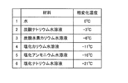
- FIG. 4 illustrates a material used as the latent heat storage material 20 that undergoes volume expansion when the phase changes from a liquid phase to a solid phase in the present embodiment.
- material 1 is water and the phase change temperature is about 0 ° C.
- Material 2 is an aqueous sodium carbonate solution with a phase change temperature of about -3 ° C.
- Material 3 is an aqueous potassium bicarbonate solution, and the phase change temperature is about ⁇ 6 ° C.
- Material 4 is an aqueous potassium chloride solution with a phase change temperature of about -11 ° C.
- Material 5 is an aqueous ammonium chloride solution with a phase change temperature of about ⁇ 16 ° C.
- Material 6 is an aqueous sodium chloride solution with a phase change temperature of about -21 ° C.
- the phase change temperature shown in FIG. 4 is a value in a saturated solution.
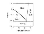
- Materials 2-6 can control the phase change temperature by adjusting the concentration of the solute. This will be described by taking the sodium chloride aqueous solution of material 6 as an example.
- FIG. 5 is a part of a phase diagram of an aqueous sodium chloride solution. The horizontal axis represents salt (sodium chloride) concentration (wt% NaCl), and the vertical axis represents temperature (° C.). As shown by the thick solid line in the figure, the phase change temperature of the aqueous sodium chloride solution is 0 ° C. when the salt concentration is 0 wt%, and is about ⁇ 21.3 ° C.
- the phase change temperature of the aqueous sodium chloride solution can be controlled between 0 ° C. and about ⁇ 21.3 ° C. by adjusting the salt concentration between 0 wt% and about 23.3 wt%.
- the latent heat storage materials 10 and 20 in this example contain a gelling agent.
- a gel refers to a gel that has a three-dimensional network structure formed by cross-linking molecules, and has absorbed and swelled a solvent therein. A gel is chemically stable without melting unless it breaks the structure.
- a gelling agent produces the effect of gelatinization only by making the latent heat storage materials 10 and 20 contain several weight%.
- the gel-like latent heat storage materials 10 and 20 are easy to handle because they can maintain a solid state as a whole before and after the phase change.
- Preferred latent heat storage materials 10 and 20 include a material A and a material 1 having a phase difference temperature difference of 6 ° C., a material D and a material 1 having a temperature difference of 5 ° C., and a temperature difference of 1 ° C. There are a material D and a material 3, a material C and a material 4 having the same temperature difference of 2 ° C., a material E and a material 6 having the same temperature difference of 4 ° C. As the latent heat storage materials 10 and 20, it is more preferable to use materials having the same phase change temperature.
- the material A (n-tetradecane) is used as the latent heat storage material 10
- the material 1 water is used as the latent heat storage material 20.
- Both the melting point of n-tetradecane (about 6 ° C.) and the melting point of water (about 0 ° C.) are included in the operating temperature range of the heat storage member 1.
- the volume change rate before and after the phase change is about 0.8 (volume contraction rate is about 20%). Further, when water undergoes a phase change from a liquid phase to a solid phase, the volume change rate before and after the phase change is about 1.1 (volume expansion rate is about 10%). Therefore, if the volume ratio of the latent heat storage material 10 (L) and the latent heat storage material 20 (L) in the liquid phase state is adjusted to about 1: 2, the volume shrinkage before and after the phase change of the latent heat storage material 10 The volume expansion amount before and after the phase change of the latent heat storage material 20 can be made equal.
- the sum of the volumes of S) can be made equal.
- the difference between the volumetric shrinkage before and after the phase change of the latent heat storage material 10 and the volume expansion amount before and after the phase change of the latent heat storage material 20 is the volume before the phase change (liquid phase state) of the latent heat storage material 10 and the latent heat storage. It is preferably within ⁇ 5% of the sum of the volume of the material 20 before the phase change (liquid phase state).
- the volume of the latent heat storage material 10 before the phase change is A
- the volume shrinkage before and after the phase change of the latent heat storage material 10 is x (x> 0)
- the volume of the latent heat storage material 20 before the phase change is B
- the volume expansion coefficient before and after the phase change of the latent heat storage material 20 is y (y> 0).
- the volume shrinkage before and after the phase change of the latent heat storage material 10 is A ⁇ x
- the volume expansion amount before and after the phase change of the latent heat storage material 20 is B ⁇ y.
- the difference (A ⁇ x ⁇ B ⁇ y) between the volume shrinkage A ⁇ x of the latent heat storage material 10 and the volume expansion amount B ⁇ y of the latent heat storage material 20 is (A + B) ⁇ ( ⁇ 0.05) ⁇ A ⁇ x ⁇ B ⁇ y ⁇ (A + B) ⁇ 0.05 It is preferable to satisfy the relationship. Thereby, the volume of the latent heat storage materials 10 (L) and 20 (L) when both are in the liquid phase state and the latent heat storage materials 10 (S) and 20 (S) when both are in the solid phase state. The difference from the volume can be reduced.
- volume change rate volume shrinkage
- volume shrinkage volume shrinkage
- volume expansion volume expansion
- a latent heat storage material stores, as heat energy, latent heat exchanged with the outside during a phase change of a substance.
- the heat of fusion at the melting point of the latent heat storage material is used.
- heat is continuously taken away from the outside at a constant phase change temperature, so that it is possible to suppress the temperature from rising above the melting point in a relatively long time.
- the container body 30 that houses the latent heat storage materials 10 and 20 is a hollow box having a rectangular parallelepiped outer shape.
- a rectangular flat plate-shaped first member 40 and a second member 50 formed in a shallow container shape as a separate body from the first member 40 are formed so that a space is formed inside. It has the structure combined with.
- the first member 40 and the second member 50 are made of, for example, a resin material such as polycarbonate.
- the second member 50 has the same shape (rectangular flat plate shape) as the first member 40, and four side surfaces provided on each side of the bottom surface portion 51 and perpendicular to the bottom surface portion 51 (FIG. a) and (b) show only two side portions 52 and 54.
- side portions 52 and 54 four side portions including the side portions 52 and 54 may be referred to as “side portions 52 and 54, etc.”). is doing.
- the bottom surface portion 51 and the side surface portions 52 and 54 form a predetermined accommodation space surrounded by five directions.
- the first member 40 and the second member 50 are joined to each other by, for example, an adhesive so that the first member 40 and the bottom surface portion 51 are arranged to face each other and the accommodation space of the second member 50 is hermetically sealed. . Thereby, an airtight space in which the latent heat storage materials 10 and 20 are accommodated is formed inside the first member 40 and the second member 50.
- the first member 40 and the second member 50 have a predetermined rigidity.
- the latent heat storage materials 10 (L) and 20 (L) in a liquid phase at room temperature are filled in an airtight space inside the container body 30 with almost no gap.
- the latent heat storage material 20 (L) is filled in layers so as to contact the entire inner surface of the bottom surface portion 51, and the latent heat storage material 10 (L) is formed on the inner surface of the first member 40. It is filled in layers so as to contact the whole.
- the heat storage member 1 When the heat storage member 1 is cooled in the refrigerator and the temperature is lowered, it first reaches the freezing point (about 6 ° C.) of the latent heat storage material 10 (n-tetradecane). When the freezing point of the latent heat storage material 10 is reached, the latent heat storage material 10 changes phase from a liquid phase to a solid phase and contracts at a volume contraction rate of about 20%. At this time, the volume of the latent heat storage material 10 changes, but the volume of the latent heat storage material 20 does not change. That is, the volume change of the latent heat storage materials 10 and 20 as a whole is smaller than that of a heat storage member using only the latent heat storage material 10. Therefore, deformation and mechanical breakage of the container body 30 can be suppressed.
- the latent heat storage material 10 n-tetradecane
- the temperature of the heat storage member 1 further decreases after the latent heat storage material 10 is solidified, it reaches the freezing point (about 0 ° C.) of the latent heat storage material 20 (water).
- the freezing point of the latent heat storage material 20 is reached, as shown in FIG. 1B, the latent heat storage material 20 undergoes a phase change from the liquid phase to the solid phase and expands at a volume expansion rate of about 10%. Due to the volume expansion of the latent heat storage material 20, the entire volume of the latent heat storage material 10 (S), 20 (S) changes in a direction approaching the entire volume of the latent heat storage material 10 (L), 20 (L) at room temperature. Therefore, deformation and mechanical breakage of the container body 30 can be suppressed.
- the melting point (about 0 ° C.) of the latent heat storage material 20 is reached. Changes from a solid phase to a liquid phase. At this time, the inside of the refrigerator is kept for a predetermined time by the latent heat of the latent heat storage material 20. When the temperature of the heat storage member 1 further rises, the melting point (about 6 ° C.) of the latent heat storage material 10 is reached, and the latent heat storage material 10 changes from a solid phase to a liquid phase. At this time, the inside of the refrigerator is kept cool for a predetermined time by the latent heat of the latent heat storage material 10. When the latent heat storage material 10 changes to the liquid phase, the heat storage member 1 returns to the state shown in FIG.
- a rectangular flat plate-like first member 40 and a shallow container-like second member 50 are formed by injection molding using polycarbonate.
- a gel-like latent heat storage material 10 is formed by containing n-tetradecane with several wt% gelling agent, and the gel-like latent heat storage material 20 is prepared by adding several wt% gelling agent to water.
- the gelling agent those suitable for gelation of n-tetradecane and water are used.
- the latent heat storage material 20 and the latent heat storage material 10 are filled without any gaps in this order in the accommodation space surrounded by the bottom surface 51 and the side surfaces 52 and 54 of the second member 50. And the outer frames of the frame-shaped end surfaces such as the side surface portions 52 and 54 of the second member 50 and the inner surface of the first member 40 so that the accommodation space filled with the latent heat storage materials 10 and 20 is hermetically sealed.
- the parts are joined using an adhesive.
- the heat storage member 1 of the present embodiment includes the first latent heat storage material 10 whose volume shrinks due to the phase change from the liquid phase to the solid phase when the temperature is lowered, and the liquid phase when the temperature is lowered. It has the 2nd latent heat storage material 20 whose volume expands by the phase change to a solid phase, and container 30 which stores both the 1st latent heat storage material 10 and the 2nd latent heat storage material 20 To do.
- the latent heat storage materials 10 and 20 as a whole between the time when the latent heat storage materials 10 and 20 are in the liquid phase state and the time when both of the latent heat storage materials 10 and 20 are in the solid phase state. Therefore, deformation and mechanical breakage of the container body 30 can be suppressed. Moreover, since the latent heat storage materials 10 and 20 can be filled in the container body 30 with almost no gap, the volume occupied by the latent heat storage materials 10 and 20 with respect to the volume of the container body 30 can be increased. Therefore, the heat storage effect per unit volume of the heat storage member 1 can be enhanced. That is, according to the present embodiment, it is possible to realize the heat storage member 1 having a high heat storage effect while suppressing deformation and mechanical damage of the container body 30 due to the volume change of the latent heat storage material.
- the heat storage member 1 of the present embodiment has a difference between the volume shrinkage before and after the phase change of the first latent heat storage material 10 and the volume expansion amount before and after the phase change of the second latent heat storage material 20.
- the volume of the latent heat storage material 10 before the phase change (liquid phase state) and the total volume of the second latent heat storage material 20 before the phase change (liquid phase state) is within ⁇ 5%. To do.
- the heat storage member 1 of the present embodiment is characterized in that the difference between the phase change temperature of the first latent heat storage material 10 and the phase change temperature of the second latent heat storage material 20 is within 7 ° C.
- the latent heat storage materials 10 and 20 are both in a liquid phase state, or both are in a solid phase state (the volume of the latent heat storage materials 10 and 20 as a whole is kept substantially constant. Since the temperature range can be widened, deformation and mechanical breakage of the container body 30 can be further suppressed.
- the heat storage member 1 of the present embodiment is characterized in that the first latent heat storage material 10 includes paraffin and the second latent heat storage material 20 includes water or an aqueous salt solution. According to this configuration, since the latent heat storage material 10 can be oily and the latent heat storage material 20 can be aqueous, even if one or both of the latent heat storage materials 10 and 20 are not gelled, The state where the latent heat storage material 10 and the latent heat storage material 20 are separated can be maintained.
- the heat storage member 1 of the present embodiment is characterized in that at least one of the first latent heat storage material 10 and the second latent heat storage material 20 contains a gelling agent. According to this configuration, since the shape of at least one of the latent heat storage materials 10 and 20 can be maintained without depending on the relationship between the arrangement posture of the heat storage member 1 and the vertical direction, the latent heat storage material 10 and the latent heat storage material 20 are maintained. Can be maintained in a separated state.
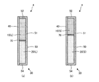
- FIG. 6A and 6B show a schematic cross-sectional configuration of the heat storage member 2 according to the present embodiment.
- symbol is attached
- the thermal storage member 2 of this Embodiment differs from the thermal storage member 1 of 1st Embodiment in each filling shape of the latent heat storage materials 10 and 20.
- the latent heat storage materials 10 and 20 are stacked in the thickness direction of the heat storage member 1, whereas the latent heat storage materials 10 and 20 of the present embodiment are the height of the heat storage member 2. It is laminated in the direction or the width direction.
- the latent heat storage material 10 is filled in the upper portion in the arrangement posture when the heat storage member 2 is used, and the latent heat storage material 20 is filled in the lower portion. That is, in this example, the latent heat storage materials 10 and 20 are laminated in the height direction of the heat storage member 2.
- the latent heat storage materials 10 (L) and 20 (L) in a liquid phase at room temperature are filled in the airtight space inside the container body 30 with almost no gap.
- the heat storage member 2 is cooled in the refrigerator and the temperature decreases, first, it reaches the freezing point (about 6 ° C.) of the latent heat storage material 10 (n-tetradecane).
- the freezing point of the latent heat storage material 10 is reached, the latent heat storage material 10 filled in the upper portion of the container body 30 changes from a liquid phase to a solid phase and contracts at a volume contraction rate of about 20%.
- the volume of the latent heat storage material 10 changes, but the volume of the latent heat storage material 20 does not change. That is, the volume change of the latent heat storage materials 10 and 20 as a whole is smaller than that of a heat storage member using only the latent heat storage material 10. Therefore, deformation and mechanical breakage of the container body 30 can be suppressed.
- the temperature of the heat storage member 2 further decreases after the latent heat storage material 10 is solidified, it reaches the freezing point (about 0 ° C.) of the latent heat storage material 20 (water).
- the freezing point of the latent heat storage material 20 is reached, as shown in FIG. 6B, the latent heat storage material 20 filled in the lower portion of the container body 30 undergoes a phase change from the liquid phase to the solid phase and has a volume of about 10%. It expands at an expansion rate. Due to the volume expansion of the latent heat storage material 20, the entire volume of the latent heat storage material 10 (S), 20 (S) changes in a direction approaching the entire volume of the latent heat storage material 10 (L), 20 (L) at room temperature. Therefore, deformation and mechanical breakage of the container body 30 can be suppressed.
- n-paraffin filled in the upper part of the container body 30 generally has a specific gravity smaller than 1, and therefore has a lower density than water, sodium chloride aqueous solution, or the like filled in the lower part of the container body 30. Furthermore, since n-paraffin is oily and water and aqueous sodium chloride solution are aqueous, they do not mix with each other. Therefore, according to the present embodiment, even if one or both of the latent heat storage materials 10 and 20 are not gelled, the latent heat storage material 10 and the latent heat storage material 20 are maintained in a separated state. can do.
- FIGS. 7A and 7B show a schematic cross-sectional configuration of the heat storage member 3 according to the present embodiment.
- symbol is attached
- the heat storage member 3 of this Embodiment is compared with the heat storage member 1 of 1st Embodiment, and the latent heat storage material 10 and the latent heat storage material 20 are the same.
- a partition plate 60 made of polycarbonate, for example is provided at the boundary.
- the partition plate 60 has a rectangular flat plate shape similar to the first member 40 and the bottom surface portion 51, for example, and is enclosed in the container body 30 together with the latent heat storage materials 10 and 20.
- the partition plate 60 can separate the filling space of the latent heat storage material 10 and the filling space of the latent heat storage material 20 in the container body 30 in a liquid-tight manner, for example.
- the partition plate 60 is movable in the thickness direction of the heat storage member 3 (in the stacking direction of the latent heat storage materials 10 and 20) along with the volume change due to the phase change of each of the latent heat storage materials 10 and 20.
- one or both of the latent heat storage materials 10 and 20 may be configured not to be gelled.
- a non-gel latent heat storage material has fluidity in a liquid phase.
- the state in which the latent heat storage material 10 and the latent heat storage material 20 are separated into layers by the partition plate 60 is maintained even when one or both of the latent heat storage materials 10 and 20 have fluidity. .
- the heat storage member 3 of the present embodiment further includes the partition plate 60 provided at the boundary between the first latent heat storage material 10 and the second latent heat storage material 20 in the container body 30. It is characterized by. According to this configuration, the state in which the latent heat storage material 10 and the latent heat storage material 20 are separated in the container body 30 can be maintained by the partition plate 60.
- the partition plate 60 is movable in accordance with the volume change of the latent heat storage materials 10 and 20. Thereby, the state in which the latent heat storage material 10 and the latent heat storage material 20 are separated can be maintained both before and after the phase change of the latent heat storage materials 10 and 20.
- the partition plate 60 liquid-tightly separates the filling space of the latent heat storage material 10 and the filling space of the latent heat storage material 20 in the container body 30. Thereby, even if at least one of the latent heat storage materials 10 and 20 is not a gel, the state where the latent heat storage material 10 and the latent heat storage material 20 are separated can be maintained.
- FIG. 8A and 8B show a schematic cross-sectional configuration of the heat storage member 4 according to the present embodiment.
- symbol is attached
- the heat storage member 4 of the present embodiment has a latent heat storage material 10 and a latent heat storage material 20 that are compared with the heat storage member 2 of the second embodiment. It is characterized in that a partition plate 70 made of, for example, polycarbonate is provided at the boundary.
- the partition plate 70 has, for example, a rectangular flat plate shape similar to the side surface portion 52 or 54 of the second member 50, and is enclosed in the container body 30 together with the latent heat storage materials 10 and 20.
- the partition plate 70 can separate the filling space of the latent heat storage material 10 and the filling space of the latent heat storage material 20 in the container body 30 in a liquid-tight manner, for example. Further, the partition plate 70 is movable in the height direction of the heat storage member 4 (in the stacking direction of the latent heat storage materials 10 and 20) in accordance with the volume change due to the phase change of each of the latent heat storage materials 10 and 20.
- one or both of the latent heat storage materials 10 and 20 may be configured not to be gelled. In the present embodiment, the state where the latent heat storage material 10 and the latent heat storage material 20 are separated by the partition plate 70 is maintained even when one or both of the latent heat storage materials 10 and 20 have fluidity.
- FIG. 9A and 9B show a schematic cross-sectional configuration of the heat storage member 5 according to the present embodiment.
- symbol is attached
- the heat storage member 5 of this Embodiment is the 1st latent heat with which the recessed part 11 was formed in the 1st member 40 side surface as a latent heat storage material with which the container body 30 was filled. It has a heat storage material 10 (L) and a second latent heat storage material 20 (L) accommodated in the recess 11.
- a plurality of concave portions 11 are formed on the surface of the latent heat storage material 10 (L) on the first member 40 side, and are arranged in a matrix when viewed from the normal direction of the surface.
- the latent heat storage material 20 (L) having substantially the same volume as the recess 11 is embedded with almost no gap.
- the latent heat storage materials 10 (L) and 20 (L) are filled in the container body 30 with almost no gap.
- the inner wall surface of the container body 30 is formed of a material having relatively high adhesion to the latent heat storage material 10.
- the heat storage member 5 is used, for example, in the arrangement posture shown in FIG. In this case, the concave 11 formation surface of the latent heat storage material 10 (L) is a horizontal upper surface. Therefore, the latent heat storage material 20 (L) is stably held in the recess 11 even if it has fluidity instead of gel.
- the heat storage member 5 When the heat storage member 5 is cooled in the refrigerator and the temperature is lowered, it first reaches the freezing point (about 6 ° C.) of the latent heat storage material 10 (n-tetradecane). When the freezing point of the latent heat storage material 10 is reached, the latent heat storage material 10 filled in the upper portion of the container body 30 changes from a liquid phase to a solid phase and contracts at a volume contraction rate of about 20%. Since the latent heat storage material 10 is highly adherent to the inner wall surface of the container body 30, the volume of the recess 11 that is not attached to the inner wall surface of the container body 30 easily expands due to the volume shrinkage, and the volume of the recess 11 is the latent heat storage material. It tends to be larger than the volume of 20 (L).
- the liquid level of the latent heat storage material 20 (L) is lower than the surface of the latent heat storage material 10 where the recess 11 is formed.
- the volume of the latent heat storage material 10 changes, but the volume of the latent heat storage material 20 does not change. That is, the volume change of the latent heat storage materials 10 and 20 as a whole is smaller than that of a heat storage member using only the latent heat storage material 10. Therefore, deformation and mechanical breakage of the container body 30 can be suppressed.
- the temperature of the heat storage member 5 further decreases after the latent heat storage material 10 is solidified, it reaches the freezing point (about 0 ° C.) of the latent heat storage material 20 (water).
- the freezing point of the latent heat storage material 20 is reached, as shown in FIG. 9B, the latent heat storage material 20 changes from a liquid phase to a solid phase and expands at a volume expansion rate of about 10%.
- the volume of the latent heat storage material 20 (S) changes in the direction approaching the volume of the recessed part 11.
- the entire volume of the latent heat storage material 10 (S), 20 (S) changes in a direction approaching the entire volume of the latent heat storage material 10 (L), 20 (L) at room temperature. Therefore, deformation and mechanical breakage of the container body 30 can be suppressed.
- the inside of the refrigerator is kept cool for a predetermined time by the latent heat of the latent heat storage material 10.
- the heat storage member 5 returns to the state shown in FIG. According to the present embodiment, the heat storage effect can be enhanced while suppressing deformation and mechanical damage of the heat storage member, as in the first embodiment.
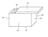
- FIG. 10 shows a schematic configuration of the heat storage container 6 according to the present embodiment.
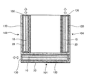
- FIG. 11 shows a schematic cross-sectional configuration of the heat storage container 6 according to the present embodiment cut along a vertical plane.
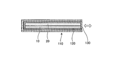
- FIG. 12 shows a schematic cross-sectional configuration of the door member 110 of the heat storage container 6 according to the present embodiment.
- symbol is attached
- the heat storage container 6 is used as a cooler box for keeping the stored items cool. As shown in FIG. 10, the heat storage container 6 of the present embodiment is attached to a rectangular parallelepiped box 100 whose upper surface is opened and rotatably attached to one side of the opening end of the box 100 via a hinge mechanism.
- the door member 110 is capable of opening and closing the opening of the box body 100.
- a cassette-type heat storage member 130 is detachably attached to the bottom surface portion 101 and the four side surface portions 102 to 105 of the box 100 (only the side surface portions 102 and 104 are shown in FIG. 11). Insertion holes 120 to be inserted are respectively formed. 12, the door member 110 is similarly formed with an insertion hole 120 into which the cassette-type heat storage member 130 is detachably inserted.
- the thick arrows in FIGS. 11 and 12 indicate the attachment / detachment direction of the heat storage member 130.
- the heat storage member 130 has substantially the same configuration as the heat storage member 1 of the first embodiment.
- the heat storage member 130 is attached so that the latent heat storage material 10 is on the inner side (container side) of the latent heat storage materials 10 and 20.
- the heat storage member 130 is attached to all six surfaces surrounding the storage space in which the stored items are stored, but the heat storage member 130 is not necessarily attached to all six surfaces. Since the cold air flows downward, it is preferable to attach the heat storage member 130 to at least the door member 110 serving as the ceiling surface of the accommodation space.
- the cassette-type heat storage member 130 is cooled in advance by a refrigerator or the like and attached to the heat storage container 6 at the time of use. According to the present embodiment, as in the first embodiment, the heat storage effect can be enhanced while suppressing deformation and mechanical damage of the cassette-type heat storage member 130.
- FIG. 13 shows a modification of the heat storage container of the present embodiment.
- the door member 110 may be a sliding door that slides parallel to the open end of the box body 100.
- the heat storage member 130 is detachably attached to the heat storage container 6. However, if the heat storage container 6 itself can be cooled by a refrigerator or the like, the heat storage member 130 is always attached to the heat storage container 6. It may be attached. Further, the heat storage container 6 may include a cooling mechanism that cools the inside of the accommodation space, and a power source that drives the cooling mechanism.
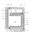
- FIG. 14 shows a schematic cross-sectional configuration of a direct-cooling refrigerator as the heat storage container 7 according to the present embodiment.
- the heat storage container 7 has a heat storage container body 201 having a rectangular parallelepiped shape that is vertically high in the installed state. In the front of the heat storage container main body 201, rectangular openings are provided in the upper and lower stages, respectively.
- a hollow box-shaped refrigeration chamber 204 is provided in the heat storage container main body 201 with the lower rectangular opening as an opening end.
- a hollow box-shaped freezer compartment 205 is provided in the heat storage container main body 201 with the upper rectangular opening as an opening end.
- the freezer compartment door 203 is shown in a closed state.
- the freezer compartment door 203 has a rectangular flat plate shape having a region that closes the rectangular opening of the freezer compartment 205 in a closed state.
- a door member 202 is attached to the open ends of the refrigerator compartment 204 and the freezer compartment 205 through a hinge mechanism (not shown) so as to be opened and closed.
- the door member 202 has a rectangular flat plate shape having a region that closes the rectangular openings of both the refrigerator compartment 204 and the freezer compartment 205 in a closed state.
- a door packing 208 for ensuring the sealing of the refrigerator compartment 204 and the freezer compartment 205 when the door is closed is provided on the side of the door member 202 facing the outer periphery including both the refrigerator compartment 204 and the freezer compartment 205.
- Each of the heat storage container main body 201 and the door member 202 has a layer configuration in which a heat insulating material is filled between the outer wall and the inner wall.
- the heat storage container 7 has a vapor compression refrigeration cycle as a cooling mechanism for cooling the refrigerator compartment 204 and the freezer compartment 205.
- the refrigeration cycle includes a compressor 230 that compresses refrigerant, a condenser (not shown) that condenses the compressed refrigerant and dissipates heat to the outside, and an expansion unit (for example, a capillary tube) (not shown) that expands the condensed refrigerant. , An evaporator (cooler) 210 that evaporates the expanded refrigerant and cools the interior with the heat of vaporization, and a pipe 220 that connects them.
- the compressor 230 is disposed on the bottom surface of the heat storage container main body 201.
- the evaporator 210 is provided between the refrigerator compartment 204 and the freezer compartment 205 inside the heat storage container main body 201.
- the lower surface of the evaporator 210 is in contact with the latent heat storage material 10 described later, and the upper surface of the evaporator 210 is exposed in the freezer compartment 205.
- the cooling mechanism an absorption cooling device or an electronic cooling device using the Peltier effect can be used.
- a heat storage member similar to the heat storage member 1 of the first embodiment is provided inside the inner wall surface of the refrigerator compartment 204 and inside the inner wall surface of the door member 202.
- a plate-like base material 240 that forms a layered space between the inner wall surface and the inner wall surface of the refrigerator compartment 204 is provided.
- the laminar space is filled with the first latent heat storage material 10 and the second latent heat storage material 20 which are stacked on each other.
- a plate-like base material 250 that forms a layered space with the inner wall surface is provided.
- the laminar space is filled with the first latent heat storage material 10 and the second latent heat storage material 20 which are stacked on each other.
- the latent heat storage materials 10 and 20 are filled so that the latent heat storage material 20 is on the inner side (the refrigerator compartment 204 side).
- the heat storage effect can be enhanced while suppressing deformation and mechanical damage of the heat storage member, as in the first to sixth embodiments.
- the present invention is not limited to the above embodiment, and various modifications can be made.
- the heat storage member which stores cold energy was mentioned as an example, this invention is applicable not only to this but the heat storage member which stores warm heat.
- the cooler box that cools the contents is described as an example, but the present invention can also be applied to a heater box that keeps the contents warm.
- the refrigerator was mentioned as an example in the said 7th Embodiment, it is applicable also to a warm storage.
- chamber of a refrigerator or a cooler box was mentioned as an example, this invention is not restricted to this, Such as a wall material of a building, a flooring, a ceiling material, etc. It can also be used for building materials, wall materials, floor materials, etc. of automobile casings.
- the arrangement of the latent heat storage material 10 and the latent heat storage material 20 may be reversed.
- the operating temperature range of a freezer (including up to the JIS One Star standard) is ⁇ 20 ° C. to ⁇ 5 ° C. For this reason, if the combination of the latent heat storage materials 10 and 20 having a phase change temperature within the same temperature range is used, a heat storage member suitable for keeping cold in the freezer can be obtained.
- the operating temperature range of the refrigerator (refrigerated room or vegetable room) is 0 ° C to 10 ° C.
- the heat storage member suitable for the cold storage in the refrigerator compartment can be obtained.
- the operating temperature range of the heat transfer liquid for air conditioning is 7 ° C to 12 ° C.
- a heat storage member suitable for cooling the air-conveying heat transfer liquid can be obtained. Efficiency of conveyance can be realized.
- the operating temperature range of the shipping container is 15 ° C to 18 ° C.
- the combination of the latent heat storage materials 10 and 20 having a phase change temperature within the same temperature range is used, a heat storage member suitable for keeping the transport container cool or warm can be obtained, and appropriate temperature transport of pharmaceuticals and the like is realized. be able to.
- the operating temperature range of the flooring and wall material that reduces the change in room temperature is 20 ° C to 30 ° C.
- a heat storage member suitable for flooring and wall materials can be obtained, realizing energy saving and indoor comfort. can do.
- the working temperature range of flooring and wall materials that store heat during the day and dissipate heat at night is 30 ° C to 40 ° C.
- the heat storage member suitable for a flooring or a wall material can be obtained, and energy saving can be implement
- the operating temperature range of the bathtub heat storage and heat insulating material is 40 ° C to 42 ° C. For this reason, if the combination of the latent heat storage materials 10 and 20 having the phase change temperature within the same temperature range is used, a heat storage member suitable for the bathtub heat storage material can be obtained, and energy saving and long-time heat storage can be realized. Can do.
- phase change materials 10 and 20 are given as examples of the phase change material, but the present invention is not limited to this.
- Phase change materials include various materials that cause a phase transition at a certain transition point.
- the present invention is widely applicable to a heat storage member and a heat storage container using a phase change material.
- Heat storage member 6 7 Heat storage container 10, 10 (L), 10 (S) First latent heat storage material 11 Recess 20, 20 (L), 20 (S) Second latent heat storage material 30 Container Body 40 First member 50 Second member 51 Bottom surface portion 52, 54 Side surface portion 60, 70 Partition plate 100 Box body 101 Bottom surface portion 102-105 Side surface portion 110, 202 Door member 120 Insertion hole 201 Thermal storage container body 203 Freezer compartment door 204 Refrigeration room 205 Freezing room 208 Door packing 210 Evaporator 220 Piping 230 Compressor 240, 250 Base material
Landscapes
- Engineering & Computer Science (AREA)
- Chemical & Material Sciences (AREA)
- Physics & Mathematics (AREA)
- Thermal Sciences (AREA)
- Mechanical Engineering (AREA)
- General Engineering & Computer Science (AREA)
- Chemical Kinetics & Catalysis (AREA)
- Combustion & Propulsion (AREA)
- Materials Engineering (AREA)
- Organic Chemistry (AREA)
Abstract
La présente invention a pour but de pourvoir à un élément de stockage de chaleur et un contenant de stockage de chaleur ayant un effet élevé de stockage de chaleur tout en diminuant une déformation et un endommagement mécanique du contenant en raison de changements dans le volume d'une matière à changement de phase. L'élément de stockage de chaleur (1) comporte une première matière de stockage de chaleur latente (10) qui se rétracte en volume en raison d'un changement de phase lorsque la température chute, une seconde matière de stockage de chaleur latente (20) qui se dilate en volume en raison d'un changement de phase lorsque la température chute et un contenant (30) qui accueille à la fois la première matière de stockage de chaleur latente (10) et la seconde matière de stockage de chaleur latente (20).
Applications Claiming Priority (2)
| Application Number | Priority Date | Filing Date | Title |
|---|---|---|---|
| JP2011137631 | 2011-06-21 | ||
| JP2011-137631 | 2011-06-21 |
Publications (1)
| Publication Number | Publication Date |
|---|---|
| WO2012176708A1 true WO2012176708A1 (fr) | 2012-12-27 |
Family
ID=47422546
Family Applications (1)
| Application Number | Title | Priority Date | Filing Date |
|---|---|---|---|
| PCT/JP2012/065369 Ceased WO2012176708A1 (fr) | 2011-06-21 | 2012-06-15 | Élément de stockage de chaleur et contenant de stockage de chaleur |
Country Status (1)
| Country | Link |
|---|---|
| WO (1) | WO2012176708A1 (fr) |
Cited By (7)
| Publication number | Priority date | Publication date | Assignee | Title |
|---|---|---|---|---|
| FR3013453A1 (fr) * | 2013-11-20 | 2015-05-22 | Mcphy Energy | Procede, jauge et systeme de mesure d'energie thermique dans des materiaux a changement de phase |
| WO2016063478A1 (fr) * | 2014-10-22 | 2016-04-28 | 株式会社デンソー | Matériau de stockage de chaleur composite |
| US20170009118A1 (en) * | 2015-07-10 | 2017-01-12 | General Electric Company | Method and apparatus for generating latent heat at low temperatures using exothermic salt crystallization |
| WO2019177544A1 (fr) * | 2018-03-15 | 2019-09-19 | Agency For Science, Technology And Research | Système de régulation thermique |
| WO2020206306A1 (fr) | 2019-04-05 | 2020-10-08 | American Aerogel Corporation | Matériaux à changement de phase non miscibles multiples contenus dans un récipient commun |
| CN112563610A (zh) * | 2019-09-10 | 2021-03-26 | 矢崎总业株式会社 | 车辆用电池组 |
| US11970652B1 (en) | 2023-02-16 | 2024-04-30 | Microera Power Inc. | Thermal energy storage with actively tunable phase change materials |
Citations (4)
| Publication number | Priority date | Publication date | Assignee | Title |
|---|---|---|---|---|
| JP2000055578A (ja) * | 1998-08-12 | 2000-02-25 | Kyushu Electric Power Co Inc | 炭素繊維を用いた蓄熱システム及びその器具 |
| JP2004067986A (ja) * | 2002-06-10 | 2004-03-04 | New Japan Chem Co Ltd | 潜熱蓄熱材及びその製造方法 |
| JP2004143229A (ja) * | 2002-10-22 | 2004-05-20 | Dai Ichi Kogyo Seiyaku Co Ltd | 潜熱蓄熱剤組成物 |
| JP2005298534A (ja) * | 2003-09-10 | 2005-10-27 | Nippon Shokubai Co Ltd | 蓄熱体及び蓄熱体を用いた蓄熱システム |
-
2012
- 2012-06-15 WO PCT/JP2012/065369 patent/WO2012176708A1/fr not_active Ceased
Patent Citations (4)
| Publication number | Priority date | Publication date | Assignee | Title |
|---|---|---|---|---|
| JP2000055578A (ja) * | 1998-08-12 | 2000-02-25 | Kyushu Electric Power Co Inc | 炭素繊維を用いた蓄熱システム及びその器具 |
| JP2004067986A (ja) * | 2002-06-10 | 2004-03-04 | New Japan Chem Co Ltd | 潜熱蓄熱材及びその製造方法 |
| JP2004143229A (ja) * | 2002-10-22 | 2004-05-20 | Dai Ichi Kogyo Seiyaku Co Ltd | 潜熱蓄熱剤組成物 |
| JP2005298534A (ja) * | 2003-09-10 | 2005-10-27 | Nippon Shokubai Co Ltd | 蓄熱体及び蓄熱体を用いた蓄熱システム |
Cited By (14)
| Publication number | Priority date | Publication date | Assignee | Title |
|---|---|---|---|---|
| FR3013453A1 (fr) * | 2013-11-20 | 2015-05-22 | Mcphy Energy | Procede, jauge et systeme de mesure d'energie thermique dans des materiaux a changement de phase |
| WO2015075387A1 (fr) * | 2013-11-20 | 2015-05-28 | Mcphy Energy | Procédé, jauge et système de mesure d'énergie thermique dans des matériaux à changement de phase |
| WO2016063478A1 (fr) * | 2014-10-22 | 2016-04-28 | 株式会社デンソー | Matériau de stockage de chaleur composite |
| JP2016079351A (ja) * | 2014-10-22 | 2016-05-16 | 株式会社デンソー | 複合蓄熱材 |
| US10155895B2 (en) | 2014-10-22 | 2018-12-18 | Denso Corporation | Composite heat storage material |
| US20170009118A1 (en) * | 2015-07-10 | 2017-01-12 | General Electric Company | Method and apparatus for generating latent heat at low temperatures using exothermic salt crystallization |
| WO2019177544A1 (fr) * | 2018-03-15 | 2019-09-19 | Agency For Science, Technology And Research | Système de régulation thermique |
| US11320212B2 (en) | 2018-03-15 | 2022-05-03 | Agency For Science, Technology And Research | Thermal control system |
| WO2020206306A1 (fr) | 2019-04-05 | 2020-10-08 | American Aerogel Corporation | Matériaux à changement de phase non miscibles multiples contenus dans un récipient commun |
| EP3948112A4 (fr) * | 2019-04-05 | 2022-11-30 | American Aerogel Corporation | Matériaux à changement de phase non miscibles multiples contenus dans un récipient commun |
| US12129094B2 (en) | 2019-04-05 | 2024-10-29 | American Aerogel Corporation | Multiple immiscible phase change materials contained in common vessel |
| CN112563610A (zh) * | 2019-09-10 | 2021-03-26 | 矢崎总业株式会社 | 车辆用电池组 |
| CN112563610B (zh) * | 2019-09-10 | 2023-12-08 | 矢崎总业株式会社 | 车辆用电池组 |
| US11970652B1 (en) | 2023-02-16 | 2024-04-30 | Microera Power Inc. | Thermal energy storage with actively tunable phase change materials |
Similar Documents
| Publication | Publication Date | Title |
|---|---|---|
| WO2012176708A1 (fr) | Élément de stockage de chaleur et contenant de stockage de chaleur | |
| JP5558415B2 (ja) | 冷蔵庫 | |
| JP6427675B2 (ja) | 真空容器 | |
| JP6293143B2 (ja) | 蓄熱部材およびそれを用いた保管容器、およびそれを用いた冷蔵庫 | |
| EP3074704B1 (fr) | Systèmes de conteneurs régulés en température à utiliser au sein d'un dispositif de réfrigération | |
| JP5800575B2 (ja) | 冷蔵庫 | |
| JP5822798B2 (ja) | 断熱箱体及びこの断熱箱体を備えた冷蔵庫 | |
| CN204630234U (zh) | 冰箱 | |
| WO1995019533A1 (fr) | Refrigerateur thermoelectrique | |
| WO2012169460A1 (fr) | Elément de stockage de chaleur | |
| KR20120025072A (ko) | 냉장고 | |
| WO2013175971A1 (fr) | Élément de stockage de chaleur, et récipient de stockage de chaleur et matériau de construction l'utilisant | |
| CN103975212B (zh) | 冰箱 | |
| CN112272750A (zh) | 保冷用具、捆包容器以及保冷对象物的运输方法 | |
| US20240350363A1 (en) | Portable temperature controlled bag with securely mounted unpowered cooling device | |
| JP7670653B2 (ja) | 保冷庫及び要冷却物の輸送方法 | |
| JP6469232B2 (ja) | 冷蔵庫 | |
| JP6006564B2 (ja) | 冷蔵庫 | |
| JP5800576B2 (ja) | 冷蔵庫 | |
| JP2017015309A (ja) | 蓄熱材充填容器、及び蓄熱槽 | |
| CN108332002A (zh) | 真空绝热材料、真空绝热材料的制造方法以及冰箱 | |
| WO2012147676A1 (fr) | Élément d'accumulation de chaleur, récipient de stockage utilisant celui-ci et procédé de fabrication d'un récipient de stockage | |
| US20200300558A1 (en) | Thermal barrier and inner heat-storage element | |
| CN211372908U (zh) | 气凝胶玻璃组件及具有其的冰箱 | |
| CN111503961B (zh) | 冰箱及真空隔热板 |
Legal Events
| Date | Code | Title | Description |
|---|---|---|---|
| 121 | Ep: the epo has been informed by wipo that ep was designated in this application |
Ref document number: 12802430 Country of ref document: EP Kind code of ref document: A1 |
|
| NENP | Non-entry into the national phase |
Ref country code: DE |
|
| 122 | Ep: pct application non-entry in european phase |
Ref document number: 12802430 Country of ref document: EP Kind code of ref document: A1 |
|
| NENP | Non-entry into the national phase |
Ref country code: JP |