EP3211119B1 - Procédé de pulvérisation cathodique et système de pulvérisation cathodique - Google Patents
Procédé de pulvérisation cathodique et système de pulvérisation cathodique Download PDFInfo
- Publication number
- EP3211119B1 EP3211119B1 EP17166364.4A EP17166364A EP3211119B1 EP 3211119 B1 EP3211119 B1 EP 3211119B1 EP 17166364 A EP17166364 A EP 17166364A EP 3211119 B1 EP3211119 B1 EP 3211119B1
- Authority
- EP
- European Patent Office
- Prior art keywords
- target
- magnet poles
- backside
- magnet
- along
- Prior art date
- Legal status (The legal status is an assumption and is not a legal conclusion. Google has not performed a legal analysis and makes no representation as to the accuracy of the status listed.)
- Active
Links
Images



Classifications
-
- C—CHEMISTRY; METALLURGY
- C23—COATING METALLIC MATERIAL; COATING MATERIAL WITH METALLIC MATERIAL; CHEMICAL SURFACE TREATMENT; DIFFUSION TREATMENT OF METALLIC MATERIAL; COATING BY VACUUM EVAPORATION, BY SPUTTERING, BY ION IMPLANTATION OR BY CHEMICAL VAPOUR DEPOSITION, IN GENERAL; INHIBITING CORROSION OF METALLIC MATERIAL OR INCRUSTATION IN GENERAL
- C23C—COATING METALLIC MATERIAL; COATING MATERIAL WITH METALLIC MATERIAL; SURFACE TREATMENT OF METALLIC MATERIAL BY DIFFUSION INTO THE SURFACE, BY CHEMICAL CONVERSION OR SUBSTITUTION; COATING BY VACUUM EVAPORATION, BY SPUTTERING, BY ION IMPLANTATION OR BY CHEMICAL VAPOUR DEPOSITION, IN GENERAL
- C23C14/00—Coating by vacuum evaporation, by sputtering or by ion implantation of the coating forming material
- C23C14/22—Coating by vacuum evaporation, by sputtering or by ion implantation of the coating forming material characterised by the process of coating
- C23C14/34—Sputtering
- C23C14/3492—Variation of parameters during sputtering
-
- C—CHEMISTRY; METALLURGY
- C23—COATING METALLIC MATERIAL; COATING MATERIAL WITH METALLIC MATERIAL; CHEMICAL SURFACE TREATMENT; DIFFUSION TREATMENT OF METALLIC MATERIAL; COATING BY VACUUM EVAPORATION, BY SPUTTERING, BY ION IMPLANTATION OR BY CHEMICAL VAPOUR DEPOSITION, IN GENERAL; INHIBITING CORROSION OF METALLIC MATERIAL OR INCRUSTATION IN GENERAL
- C23C—COATING METALLIC MATERIAL; COATING MATERIAL WITH METALLIC MATERIAL; SURFACE TREATMENT OF METALLIC MATERIAL BY DIFFUSION INTO THE SURFACE, BY CHEMICAL CONVERSION OR SUBSTITUTION; COATING BY VACUUM EVAPORATION, BY SPUTTERING, BY ION IMPLANTATION OR BY CHEMICAL VAPOUR DEPOSITION, IN GENERAL
- C23C14/00—Coating by vacuum evaporation, by sputtering or by ion implantation of the coating forming material
- C23C14/22—Coating by vacuum evaporation, by sputtering or by ion implantation of the coating forming material characterised by the process of coating
- C23C14/34—Sputtering
- C23C14/3407—Cathode assembly for sputtering apparatus, e.g. Target
-
- C—CHEMISTRY; METALLURGY
- C23—COATING METALLIC MATERIAL; COATING MATERIAL WITH METALLIC MATERIAL; CHEMICAL SURFACE TREATMENT; DIFFUSION TREATMENT OF METALLIC MATERIAL; COATING BY VACUUM EVAPORATION, BY SPUTTERING, BY ION IMPLANTATION OR BY CHEMICAL VAPOUR DEPOSITION, IN GENERAL; INHIBITING CORROSION OF METALLIC MATERIAL OR INCRUSTATION IN GENERAL
- C23C—COATING METALLIC MATERIAL; COATING MATERIAL WITH METALLIC MATERIAL; SURFACE TREATMENT OF METALLIC MATERIAL BY DIFFUSION INTO THE SURFACE, BY CHEMICAL CONVERSION OR SUBSTITUTION; COATING BY VACUUM EVAPORATION, BY SPUTTERING, BY ION IMPLANTATION OR BY CHEMICAL VAPOUR DEPOSITION, IN GENERAL
- C23C14/00—Coating by vacuum evaporation, by sputtering or by ion implantation of the coating forming material
- C23C14/22—Coating by vacuum evaporation, by sputtering or by ion implantation of the coating forming material characterised by the process of coating
- C23C14/34—Sputtering
- C23C14/3485—Sputtering using pulsed power to the target
-
- C—CHEMISTRY; METALLURGY
- C23—COATING METALLIC MATERIAL; COATING MATERIAL WITH METALLIC MATERIAL; CHEMICAL SURFACE TREATMENT; DIFFUSION TREATMENT OF METALLIC MATERIAL; COATING BY VACUUM EVAPORATION, BY SPUTTERING, BY ION IMPLANTATION OR BY CHEMICAL VAPOUR DEPOSITION, IN GENERAL; INHIBITING CORROSION OF METALLIC MATERIAL OR INCRUSTATION IN GENERAL
- C23C—COATING METALLIC MATERIAL; COATING MATERIAL WITH METALLIC MATERIAL; SURFACE TREATMENT OF METALLIC MATERIAL BY DIFFUSION INTO THE SURFACE, BY CHEMICAL CONVERSION OR SUBSTITUTION; COATING BY VACUUM EVAPORATION, BY SPUTTERING, BY ION IMPLANTATION OR BY CHEMICAL VAPOUR DEPOSITION, IN GENERAL
- C23C14/00—Coating by vacuum evaporation, by sputtering or by ion implantation of the coating forming material
- C23C14/22—Coating by vacuum evaporation, by sputtering or by ion implantation of the coating forming material characterised by the process of coating
- C23C14/34—Sputtering
- C23C14/35—Sputtering by application of a magnetic field, e.g. magnetron sputtering
-
- C—CHEMISTRY; METALLURGY
- C23—COATING METALLIC MATERIAL; COATING MATERIAL WITH METALLIC MATERIAL; CHEMICAL SURFACE TREATMENT; DIFFUSION TREATMENT OF METALLIC MATERIAL; COATING BY VACUUM EVAPORATION, BY SPUTTERING, BY ION IMPLANTATION OR BY CHEMICAL VAPOUR DEPOSITION, IN GENERAL; INHIBITING CORROSION OF METALLIC MATERIAL OR INCRUSTATION IN GENERAL
- C23C—COATING METALLIC MATERIAL; COATING MATERIAL WITH METALLIC MATERIAL; SURFACE TREATMENT OF METALLIC MATERIAL BY DIFFUSION INTO THE SURFACE, BY CHEMICAL CONVERSION OR SUBSTITUTION; COATING BY VACUUM EVAPORATION, BY SPUTTERING, BY ION IMPLANTATION OR BY CHEMICAL VAPOUR DEPOSITION, IN GENERAL
- C23C14/00—Coating by vacuum evaporation, by sputtering or by ion implantation of the coating forming material
- C23C14/22—Coating by vacuum evaporation, by sputtering or by ion implantation of the coating forming material characterised by the process of coating
- C23C14/34—Sputtering
- C23C14/35—Sputtering by application of a magnetic field, e.g. magnetron sputtering
- C23C14/351—Sputtering by application of a magnetic field, e.g. magnetron sputtering using a magnetic field in close vicinity to the substrate
-
- H—ELECTRICITY
- H01—ELECTRIC ELEMENTS
- H01J—ELECTRIC DISCHARGE TUBES OR DISCHARGE LAMPS
- H01J37/00—Discharge tubes with provision for introducing objects or material to be exposed to the discharge, e.g. for the purpose of examination or processing thereof
- H01J37/32—Gas-filled discharge tubes
- H01J37/34—Gas-filled discharge tubes operating with cathodic sputtering
- H01J37/3402—Gas-filled discharge tubes operating with cathodic sputtering using supplementary magnetic fields
- H01J37/3405—Magnetron sputtering
-
- H—ELECTRICITY
- H01—ELECTRIC ELEMENTS
- H01J—ELECTRIC DISCHARGE TUBES OR DISCHARGE LAMPS
- H01J37/00—Discharge tubes with provision for introducing objects or material to be exposed to the discharge, e.g. for the purpose of examination or processing thereof
- H01J37/32—Gas-filled discharge tubes
- H01J37/34—Gas-filled discharge tubes operating with cathodic sputtering
- H01J37/3411—Constructional aspects of the reactor
- H01J37/3414—Targets
- H01J37/3426—Material
-
- H—ELECTRICITY
- H01—ELECTRIC ELEMENTS
- H01J—ELECTRIC DISCHARGE TUBES OR DISCHARGE LAMPS
- H01J37/00—Discharge tubes with provision for introducing objects or material to be exposed to the discharge, e.g. for the purpose of examination or processing thereof
- H01J37/32—Gas-filled discharge tubes
- H01J37/34—Gas-filled discharge tubes operating with cathodic sputtering
- H01J37/3411—Constructional aspects of the reactor
- H01J37/345—Magnet arrangements in particular for cathodic sputtering apparatus
- H01J37/3455—Movable magnets
-
- H—ELECTRICITY
- H01—ELECTRIC ELEMENTS
- H01J—ELECTRIC DISCHARGE TUBES OR DISCHARGE LAMPS
- H01J37/00—Discharge tubes with provision for introducing objects or material to be exposed to the discharge, e.g. for the purpose of examination or processing thereof
- H01J37/32—Gas-filled discharge tubes
- H01J37/34—Gas-filled discharge tubes operating with cathodic sputtering
- H01J37/3464—Operating strategies
- H01J37/3467—Pulsed operation, e.g. HIPIMS
Definitions
- the present invention is directed to a method of sputter coating, especially of HIPIMS sputter coating substrates and to a HIPIMS sputter system.
- PVD deposition technology for the processing of substrates in a vacuum treatment system is widely known.
- a magnet system behind a sputtering target to define a magnetic tunnel located on a surface of a target material, the sputtering surface, the tunnel confining the plasma during operation.
- the erosion of the target caused by magnetron sputtering results in the formation of a so called racetrack, a trench in the target material. If the trench has consumed the thickness of the target, the target needs to be exchanged; this also defines for the target-lifetime.
- the erosion pattern may consist of an outer main erosion groove and one or more weaker inner erosion grooves towards the centre of the target.
- the outer main erosion groove is required for a good deposition uniformity to cope with the limited target diameter. The smaller the target diameter in relation to the substrate diameter is the more pronounced the outer erosion groove has to be so as to compensate the edge effect. Since thus during target life erosion will specifically affect the outer main groove, consequently the influence of the magnetic field is getting stronger in this location due to the fact, that there the target becomes thinner and thinner. As a result the discharge current rises and the voltage decreases for a fixed discharge power.
- a sputter deposition system's control system runs a user-defined program or recipe and allows adjusting either the deposition time or the discharge power to get the same film thickness throughout the entire target life.
- a change of the voltage/current ratio is of no problem since the rate is defined by the discharge power.
- the uniformity can be adjusted over target life by lateral magnet movement, like it is described in US 6 821 397 B2 .
- the increasing magnetic field significantly changes the process conditions.
- One example is the sputtering of ferromagnetic materials, where the magnetic field strongly increases due to thinning of the target.
- Another application is sputtering with pulsed DC with very high currents and low duty cycles, also known as HIPIMS or HPPMS.
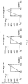
- Fig. 1 shows by example the significant change of the current rise and the pulse peak value as a function of the applied target voltage with a 100 ⁇ sec pulse on a Ti target with otherwise unchanged conditions.
- Fig. 1 Due to the highly dynamic situation of the pulsing as illustrated in Fig. 1 it is obvious that the pulse power may experience significant changes from start to end of target life.
- the HIPIMS process requires a constant peak current over target life, since it is the peak current that is directly correlated with the ionization degree of the discharge and the ionization degree itself is the driving parameter to enable via filling in deep features (see: Society of Vacuum Coaters 505/856-7188, 52nd Annual Technical Conference Proceedings, Santa Clara, CA, May 9-14, 2009 ISSN 0737-5921 ).
- Film thickness control can be done by adjustment of the sputter power over target life or by adjustment of the process time.
- the sputter power or the process time have to be increased since by the target erosion the target surface moves "away" from the substrate resulting in an effectively higher target to substrate distance.
- the magnetic field driving the plasma increases, which results in an increasing target current and in a decreasing target voltage.
- the current/voltage ratio is not of importance.
- highly dynamic pulsed processes like HIPIMS voltage and current needs to be kept constant during target life for the following reasons:
- performing controllably increasing of distances of the at least predominant number of magnet poles along at least one of the outer and of the inner first sections is done in a manner so as to maintain peak current pulse values of the HIPIMS operation at least approx. constant over lifetime of the target.
- the magnet arrangement comprises a single pair of the addressed closed loops.
- the distances to the backside of the at least predominant number of magnet poles of the outer and of the inner second section, both in the second part are increased by an equal movement from the backside and parallel to the rotational axis. This means that even if the initial distances from the backside of the addressed magnet poles are different, the respective distances are increased by the addressed equal movement equally.
- the distances to the backside of the at least predominant number of magnet poles of the outer and of the inner second sections, in the second part are kept constant during HIPIMS operation time of the target i.e. during lifetime of the target.
- the distances of the at least predominant number of magnet poles of the outer and of the inner second sections are equal during HIPIMS operation time of the target.
- controllably increasing the distances of the at least predominant number of magnet poles along at least one of the outer and of the inner first sections, in the first part, to the backside is performed upon magnet poles along the outer as well as upon magnet poles along the inner first sections.
- the distances to the backside of the at least predominant number of magnet poles of the at least one of the outer and of the inner first sections are increased by an equal movement considered in direction from said backside and parallel to said rotational axis.
- the distances to the backside of the at least predominant number of magnet poles of the at least one of the outer and of the inner first section are equal during HIPIMS operation time of the target.
- the distances of magnet poles along the outer and inner first section are equal during HIPIMS operation time of the target and wherein distances from magnet poles along the outer and the inner second section are equal as well during the addressed HIPIMS operation time of the target.
- an average distance from the rotational axis of the magnet poles along the first outer section is larger than an average distance from said rotational axis of magnet poles along the second outer section.
- the distances of the magnet poles along the outer as well as along the inner first sections to the backside are controllably increased.
- controllably increasing the distances of the at least predominant number of magnet poles along at least one of the outer and of the inner first sections to the backside is performed at least one of stepwise and of steadily during the HIPIMS operation time of the target.
- controllably increasing the distances of the at least predominant number of magnet poles along the at least one of the outer and of the inner first sections is performed in dependency of erosion depths of the sputtering surface adjacent to the periphery of the target and is thereby, in a further good embodiment, selected approx. equal to the erosion depth of the sputtering surface adjacent to the periphery of the target.
- controllably increasing the distances of the at least predominant number of magnet poles along the at least one of the outer and of the inner first sections is controlled by a predetermined distance vs. time characteristic.
- the magnet poles are magnet poles of magnets arranged with their dipole direction at least substantially parallel to the rotational axis.
- a sputter system which comprises a target arrangement with a sputtering surface and with a back surface.
- the system further comprises a magnet arrangement along the back surface of the target arrangement and a pivoting or rotating drive which is operationally connected to the magnet arrangement so as to pivot or rotate the magnet arrangement about a rotational axis perpendicular to the back surface of the target arrangement.
- the magnet arrangement comprises magnet poles arranged along a pair of closed loops, an outer of the closed loops of the pair completely surrounding an inner of the closed loops of the pair and being distant from the inner of the closed loops.
- the magnet poles which face the backside of the target arrangement and which are arranged along one of the closed loops of the pair have opposite magnet polarity with respect to polarity of the magnet poles facing the backside and arranged along the other of the closed loops of the pair.
- the magnet arrangement is subdivided in a first part and in a second part, the outer closed loop of the pair is thereby subdivided in a first outer section on the first part and in a second outer section on the second part and the inner closed loop of the pair is respectively thereby subdivided in a first inner section on the first part and in a second inner section on the second part.
- the first outer section is thereby more distant from the rotational axis than the second outer section, both considered in radial direction with respect to the rotational axis.
- a displacement drive is operationally interconnected between the first part and the second part.
- a HIPIMS supply generator is operationally connected to the target arrangement.
- a displacement control unit is operationally connected to the HIPIMS supply generator and to the displacement drive and is adapted to control the displacement drive in dependency of operation time of the HIPIMS supply generator upon the target so as to move the first part more apart from the backside of the target than the second part is moved apart from the backside.
- pivoting or rotating drive and the displacement drive are both stationarily mounted with respect to the target arrangement.
- the solution departs most generically from a magnet arrangement with axial adjustment parts thereof as described e.g. in the EP_01908090_B1, but is adapted for HIPIMS sputtering by the inner part being e.g. axially stationar whereas the outer part being retracted from the target backside (i.e. increasing the distance of the outer part of the magnet arrangement to the backside of the target) over the target life, i.e. during HIPIMS operation time of the target. In a first approximation such retraction may equal the erosion depth of the target.
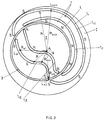
- a target arrangement as may be exploited in the frame of the present invention i.e. for properly controlling pulse current peak values of HIPIMS operation, is shown in fig. 3 in top view.
- the magnet arrangement comprises magnet poles which are arranged along a pair 1 of closed loops, namely of an outer loop 1 o and an inner loop 1 i .
- the outer loop 1 o in fact as a geometric locus, completely surrounds the inner loop 1 i , in fact a geometric locus as well.
- the two loops of the pair 1 are mutually distant.
- the magnet poles which, as will be apparent from the following description, face the backside of a target arrangement and which are arranged along one of the closed loops, let's say loop 1 o of the pair 1, have opposite magnet polarity, as an example S, with respect to the polarity -N- of the magnet poles facing the addressed backside and arranged along the other closed loop, let's say 1 i , of the pair 1.
- the addressed poles are arranged along the addressed loop 1 i , 1 o in such a way that the respective poles in fact form a continuous pole surface, but may also be mutually separated or spaced, considered along respective loops.
- the pair 1 of closed loops 1 o and 1 i is subdivided in a first part I and in a second part II as by an annular gap 3.
- the entire magnet arrangement is further rotatably or pivotably mounted about a rotational axis A, perpendicular to the plane of fig. 3 and is (not shown in fig. 3 ) operationally coupled to a pivoting or rotational drive.
- the outer loop 1 o is subdivided in a first outer section 1 oI which resides on the first part I and in a second outer section 1 oII which resides on the second part II.
- the inner closed loop 1 i is thereby subdivided in a first inner section 1 iI residing on the first part I and in a second inner section 1 iII residing on the second part II.
- Each magnet pole or each locus along the first outer section 1 oI as well as along the second outer section 1 oII defines with respect to rotational axis A or is radially distant from rotation axis A, by a distance R.
- the average of this distance R all along the first outer section 1 oI is larger than the average of that distance R along the second outer section 1 oII .
- the outer loop 1 o is eccentric with respect to rotational axis A and so is the overall pair of closed loops 1.
- first outer section 1 oI defines a first locus L max where R is maximum, R max .
- one second locus L min along the second outer section 1 oII defines for a minimum R, R min .
- the left-hand limit L e1 of part I is at most there, where the addressed relation prevails, but the L e1 may be closer towards L max .
- the addressed limit is the maximum limit for the right-hand extent of the first outer section 1 oI with respect to the locus L max .
- the right-hand limit locus L e2 is realized or exploited by the exemplary magnet arrangement, whereas the left-hand limit locus L e1 is not exploited as the left-hand limit of the first outer section 1 oI is closer to the first locus L max .
- the magnet arrangement becomes highly suited to perform, in the frame of the present invention, pulse current peak control of HIPIMS operation of the target associated with the addressed magnet arrangement.
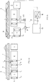
- fig. 4a and fig. 4b show respective cross sections through a target arrangement with associated magnet arrangement as e.g. exemplified with the help of fig. 3 .
- Fig. 4a shows relative positioning of the magnet arrangement and target backside 7, when the target is new, i.e. not yet sputter eroded
- fig. 4b shows the target eroded by HIPIMS sputter operation and the respective qualitative positioning of the magnet arrangement to cope with the rising current pulse values according to the present invention.
- Those parts in fig. 4a and 4b which accord with the magnet arrangement parts as were presented with the help of fig. 3 are addressed in fig. 4 by the same reference numbers.
- the magnets 5 which provide for the magnet poles N and S respectively according to fig. 3 and arranged along the respective closed loops and facing backside 7 of the target arrangement 9 with a sputtering surface 11, are arranged, in a good embodiment, with dipole axes D perpendicular to the backside 7 of target arrangement 9.
- part I of the magnet arrangement As was exemplified with the help of fig. 3 , part I of the magnet arrangement as was exemplified with the help of fig. 3 , assumes an initial distance d oI from the backside 7 of the target arrangement 9. The second part II as well assumes an initial distance d oII from the addressed backside 7 of the target arrangement 9. d oI is, in a good embodiment, equal to d oII , which nevertheless is not mandatory. As consumption of the target arrangement 9 proceeds and erosion E (see fig. 4b ) increases, part I of the magnet arrangement is retracted from the backside 7 of the target arrangement 9 as denoted in fig. 4b by d tI .
- both parts I and II as schematically shown in the figures 4 are in combination rotated about rotational axis A or are pivoted thereabout as schematically addressed by the arrow ⁇ in fig. 4b .
- the representations in fig. 4a and fig. 4b are taken at the same angular position of the magnet arrangement with respect to rotational axis A.
- a HIPIMS pulse generator unit 13 which, as schematically shown by line 15, operates the target arrangement 9.
- the operation time T of target arrangement 9 under HIPIMS operational condition is sensed and registered.
- a control unit 19 controls a drive 21 operationally connected between the two parts I and II of the magnet arrangement so as to controllably increase the distance d tI with respect to part II in dependency of the overall HIPIMS operating time T of target arrangement 9.
- the characteristic of d tI increase in dependency HIPIMS operating time T of target arrangement 9 is in a good embodiment predetermined by experiments and stored in control unit 19.
- the drive 23 in fig. 4b addresses the rotational drive for the overall magnet arrangement with parts I and II.
- Fig. 5 shows, as an example, a good design of a magnet arrangement drive system so as to control especially the distance d tI of part I of the magnet arrangement as was exemplified with the help of the figures 3 and 4 .
- a carrier II' for part II of the magnet arrangement is connected to the rotational drive 23' according to drive 23 as schematically shown in fig. 4b .
- the drive 23' an electric motor, is drivingly connected by a belt 25 to a hollow shaft 27, which is connected by a member 29 to the carrier II'.
- a carrier I' for the part I of the magnet arrangement as was exemplified with the help of the figs. 3 and 4 is carried by three spindles 31 upon carrier II'.
- the three spindles 31 are provided with a 120° angular spacing about rotational axis A.
- lift drive 35 in analogy to drive 21, as schematically shown in fig. 4b e.g. an electric motor.
- the drive 35 as well as drive 23' are firmly mounted to a stationary frame part 37.
- An axle 41 coaxial to rotational axis A is rotationally driven by drive 35 and is provided at its end, pointing towards carrier II' with a gear wheel or pinion 43.
- the pinion 43 meshes with the gear wheels 33.
- the pinion 43 is run at a different angular velocity, at a higher one or lower one, which ever direction of movement of carrier I' with respect to carrier II' with the respective parts of the magnet arrangement, is desired.
- carrier I' e.g. mounted on a jacket 45
- a reflector plate so as to monitor the axial position of carrier I' by a distance sensor (not shown), e.g. by a laser triangulation sensor.
- the addressed drive system as exemplified by fig. 5 comprises the two drives for rotational movement about axis A, drive 23' as well as for displacement of carrier I' with respect to carrier II', drive 35, whereby both drives are stationary with respect to a frame 37 and thus to the target with the advantage that the electric connections to the addressed drives are stationary.
- the addressed sections may be displaced unequally with respect to the back surface 7 of the target arrangement 9 during HIPIMS operation time T, which on one hand would weaken the effect of such displacement and on the other hand would shift the apex of the magnetic field M upon the sputtering surface of target arrangement 9.
- the two sections may have an initial distance from the backside 7 of the target arrangement which are different, thereby being further displaced by equal or by different amounts.
- This may be realized e.g. to take in account the varying distances of the magnet poles along the addressed sections from the periphery of the target arrangement 9.
- All or at least a part of the magnet poles upon carrier II' may be displaced too from the backside 7 of target arrangement 9 during HIPIMS operation time of the target arrangement 9, but, in any case, less than at least the predominant number of magnet poles along the section 1 oI and/or 1 iI are retracted during the addressed lifetime of the target.
- the magnet poles along the second outer section 1 oII and/or along the second inner section 1 iII may have, as described in the example, equal distances with respect to the backside 7 of target arrangement 9 irrespective whether displaced or not displaced during the HIPIMS operation time of the target arrangement 9.
- a minor number of the addressed magnet poles of part II of the magnet arrangement may be displaced differently from the backside 7 of target arrangement 9 than the predominant number of the addressed poles along the section 1 oII and/or section 1 iII .
- the predominant part of magnet poles arranged along the first outer and/or first inner sections 1 oI , 1 iI are moved by larger amounts from the backside of the target arrangement 9 than at least a predominant number of magnet poles along the second outer section and/or the second inner section 1 iII , 1 oII are moved or displaced from the backside of the target arrangement 9 during HIPIMS operation time of the target arrangement 9, and thus during lifetime of such target.
- current pulse peak values supplied by HIPIMS operation of the target may be properly controlled during lifetime of the target considered and may especially be controlled to be substantially constant over the addressed lifetime.
Landscapes
- Chemical & Material Sciences (AREA)
- Engineering & Computer Science (AREA)
- Chemical Kinetics & Catalysis (AREA)
- Materials Engineering (AREA)
- Mechanical Engineering (AREA)
- Metallurgy (AREA)
- Organic Chemistry (AREA)
- Physics & Mathematics (AREA)
- Plasma & Fusion (AREA)
- Analytical Chemistry (AREA)
- Physical Vapour Deposition (AREA)
Claims (22)
- Un procédé de revêtement par pulvérisation cathodique de substrats comprenant• fournir une cible avec une surface de pulvérisation cathodique et avec une surface arrière• fournir le long de ladite surface arrière un agencement d'aimant• faire pivoter ou faire tourner ledit agencement d'aimant autour d'un axe de rotation qui est perpendiculaire à ladite surface arrière• où ledit agencement d'aimants comprend des pôles magnétiques agencés le long d'une paire de boucles fermées, une boucle extérieure desdites boucles fermées de ladite paire entourant complètement une boucle intérieure desdites boucles fermées de ladite paire et étant éloignée de ladite boucle intérieure desdites boucles fermées,• les pôles magnétiques faisant face audit surface arrière et agencés le long d'une desdites boucles fermées de ladite paire ayant une polarité d'aimant opposée par rapport aux pôles magnétiques faisant face audit surface arrière et agencés le long de l'autre desdites boucles fermées de ladite paire,• où ladite paire de boucles fermées est subdivisée en une première partie et en une deuxième partie, ladite boucle fermée extérieure de ladite paire étant ainsi subdivisée en une première section extérieure dans ladite première partie et en une deuxième section extérieure dans ladite deuxième partie et ladite boucle fermée intérieure de ladite paire étant ainsi subdivisée en une première section intérieure dans ladite première partie et en une deuxième section intérieure dans ladite deuxième partie,• ladite première section extérieure étant plus éloignée dudit axe de rotation que ladite deuxième section extérieure, toutes les deux considérées dans une direction radiale par rapport audit axe de rotation,• ledit procédé comprenant l'augmentation de façon contrôlée des distances d'au moins un nombre prédominant de pôles magnétiques le long d'au moins une desdites premières sections extérieures et intérieures vers ladite surface arrière plus que l'augmentation des distances vers ladite surface arrière d'au moins un nombre prédominant de pôles magnétiques desdites deuxièmes sections extérieures et intérieures, pendant que le temps d'opération de ladite cible augmente.
- Le procédé selon la revendication 1, réalisant ainsi ladite augmentation contrôlée desdites distances dudit nombre au moins prédominant de pôles magnétiques le long d'au moins l'une desdites premières sections extérieures et intérieures afin de maintenir des valeurs d'impulsions de courant de crête de ladite opération essentiellement constante sur la durée de vie de ladite cible.
- Le procédé selon la revendication 1 ou 2, où ledit agencement d'aimant comprend une seule paire desdites boucles fermées.
- Le procédé selon l'une des revendications 1 à 3, où lesdites distances à ladite surface arrière dudit nombre au moins prédominant de pôles magnétiques desdites deuxièmes sections extérieures et desdites deuxièmes sections intérieures sont augmentées d'un mouvement égal considéré dans la direction à partir de ladite surface arrière et parallèle audit axe de rotation.
- Le procédé selon l'une des revendications 1 à 4, où lesdites distances à la surface arrière dudit nombre au moins prédominant de pôles magnétiques desdites deuxièmes sections extérieures et desdites deuxièmes sections intérieures sont maintenues constantes pendant le temps d'opération de ladite cible.
- Le procédé selon l'une des revendications 1 à 5, où les distances dudit nombre au moins prédominant de pôles magnétiques desdites deuxièmes sections extérieures et desdites deuxièmes sections intérieures sont égales pendant ledit temps d'opération de ladite cible.
- Le procédé selon l'une des revendications 1 à 6, où en augmentant de manière contrôlée lesdites distances dudit nombre au moins prédominant de pôles magnétiques le long d'au moins l'une desdites premières sections extérieures et intérieures vers la surface arrière, est effectuée sur des pôles magnétiques le long desdites premières sections extérieures et intérieures.
- Le procédé selon l'une des revendications 1 à 7, où les distances dudit nombre au moins prédominant de pôles magnétiques le long d'au moins l'une desdites premières sections extérieures et intérieures sont également augmentées.
- Le procédé selon l'une des revendications 1 à 8, où lesdites distances à ladite surface arrière dudit nombre au moins prédominant de pôles magnétiques de ladite au moins une desdites premières sections extérieures et intérieures sont augmentées d'un mouvement égal considéré dans la direction à partir de ladite surface arrière et parallèle audit axe de rotation.
- Le procédé selon l'une des revendications 1 à 9, où lesdites distances à ladite surface arrière dudit nombre au moins prédominant de pôles magnétiques de ladite au moins une desdites premières sections extérieures et intérieures sont égales pendant le temps d'opération de ladite cible.
- Le procédé selon l'une des revendications 1 à 10, où lesdites distances des pôles magnétiques le long desdites premières sections extérieures et intérieures sont égales pendant le temps d'opération et où les distances des pôles magnétiques le long desdites deuxièmes sections extérieures et intérieures sont égales ainsi pendant le temps d'opération de ladite cible.
- Le procédé selon l'une des revendications 1 à 10, où une distance moyenne dudit axe de rotation des pôles magnétiques le long de ladite première section extérieure est supérieure à une distance moyenne dudit axe de rotation des pôles magnétiques le long de ladite deuxième section extérieure.
- Le procédé selon l'une des revendications 1 à 12, comprenant l'augmentation de manière contrôlée des distances de tous les pôles magnétiques le long d'au moins l'une desdites premières sections extérieures et desdites premières sections intérieures à ladite surface arrière.
- Le procédé selon la revendication 13, comprenant l'augmentation de manière contrôlée desdites distances desdits pôles magnétiques le long desdites premières sections extérieures ainsi que le long desdites premières sections intérieures à ladite surface arrière.
- Le procédé selon l'une des revendications 1 à 14, où un premier lieu le long de ladite première section extérieure définit une distance maximale Rmax à partir dudit axe de rotation et où un deuxième lieu le long de la deuxième section extérieure définit une distance minimale Rmin à partir dudit axe de rotation et où ladite première partie est limitée d'un côté dudit premier locus par un premier lieu de limite qui a une distance Re1 à partir dudit axe de rotation qui n'est pas inférieure à


- Le procédé selon l'une des revendications 1 à 15, où en augmentant de façon contrôlée lesdites distances dudit nombre au moins prédominant de pôles magnétiques le long de ladite au moins une desdites premières sections extérieures et desdites premières sections intérieures vers la surface arrière est exécutée au moins l'une de manière échelonnée et de manière constante pendant ledit temps d'opération de ladite cible.
- Le procédé selon l'une des revendications 1 à 16, où en augmentant de façon contrôlée lesdites distances dudit nombre au moins prédominant de pôles magnétiques le long d'au moins l'une desdites premières sections extérieures et desdites premières sections intérieures est effectuée en fonction de la profondeur d'érosion de ladite surface de pulvérisation cathodique adjacente à la périphérie de ladite cible et est de préférence sélectionnée à env. égale à la profondeur d'érosion de ladite surface de pulvérisation cathodique adjacente à ladite périphérie de ladite cible.
- Le procédé selon l'une des revendications 1 à 17, où en augmentant de façon contrôlée lesdites distances dudit nombre au moins prédominant de pôles magnétiques le long d'au moins l'une desdites premières sections extérieures et desdites premières sections intérieures est commandée par une caractéristique de distance prédéterminée contre le temps.
- Le procédé selon l'une des revendications 1 à 18, où lesdits pôles magnétiques sont des pôles magnétiques d'aimants agencés avec leurs directions de dipôle au moins essentiellement parallèles audit axe de rotation.
- Un système de pulvérisation cathodique comprenant• un agencement de cible avec une surface de pulvérisation cathodique et une surface arrière• un agencement d'aimants le long de ladite surface arrière• un entraînement pivotant ou tournant relié de manière fonctionnelle audit agencement d'aimant pour pivoter ou faire tourner ledit agencement d'aimant autour d'un axe de rotation perpendiculaire à ladite surface arrière• ledit agencement d'aimants comprenant des pôles magnétiques agencés le long d'une paire de boucles fermées, une boucle extérieure desdites boucles fermées de ladite paire entourant complètement une boucle intérieure desdites boucles fermées de ladite paire et étant éloignée de ladite boucle interne desdites boucles fermées• les pôles magnétiques faisant face à ladite surface arrière et agencés le long de l'une desdites boucles fermées de ladite paire ayant une polarité opposée de l'aimant par rapport aux pôles magnétiques tournés vers ladite surface arrière et agencés le long de l'autre desdites boucles fermées de ladite paire• où ledit agencement d'aimant est subdivisé en une première partie et en une deuxième partie, ladite boucle fermée extérieure de ladite paire étant ainsi subdivisée en une première section extérieure sur ladite première partie et en une deuxième section extérieure sur ladite deuxième partie et ladite boucle fermée intérieure de ladite paire étant ainsi subdivisée en une première section intérieure sur ladite première partie et en une deuxième section intérieure sur ladite deuxième partie• ladite première section externe étant plus éloignée dudit axe de rotation que ladite deuxième section extérieure, toutes les deux considérées dans une direction radiale par rapport audit axe de rotation• un mécanisme de déplacement interconnecté de manière opérationnelle entre ladite première partie et ladite deuxième partie• un générateur d'alimentation connecté de manière opérationnelle à ladite cible• une unité de commande de déplacement connectée de manière opérationnelle audit générateur d'alimentation et audit entraînement de déplacement et adaptée pour commander ladite commande de déplacement en fonction de l'opération dudit générateur d'alimentation sur ladite cible afin de déplacer ladite première partie à partir de ladite surface arrière de ladite cible plus que ladite deuxième partie est déplacée à partir de ladite surface arrière.
- Le système de pulvérisation cathodique selon la revendication 20, où ledit entraînement de pivotement ou de rotation et ledit entraînement de déplacement sont tous les deux montés de façon fixe par rapport audit agencement de cible.
- Le procédé selon l'une des revendications 1 à 19 ou le système de pulvérisation cathodique selon l'une des revendications 20 à 21, où la tension est maintenue constante pendant le temps d'opération de ladite cible et/ou la cible comprenant un matériau ferromagnétique.
Applications Claiming Priority (3)
| Application Number | Priority Date | Filing Date | Title |
|---|---|---|---|
| US201361762439P | 2013-02-08 | 2013-02-08 | |
| PCT/EP2014/052402 WO2014122250A1 (fr) | 2013-02-08 | 2014-02-07 | Procédé de pulvérisation magnétron pulsé à haute puissance (hipims) et système de dispositif de pulvérisation hipims |
| EP14704312.9A EP2954092B1 (fr) | 2013-02-08 | 2014-02-07 | Procédé de pulvérisation magnétron pulsé à haute puissance (hipims) et système de dispositif de pulvérisation hipims |
Related Parent Applications (1)
| Application Number | Title | Priority Date | Filing Date |
|---|---|---|---|
| EP14704312.9A Division EP2954092B1 (fr) | 2013-02-08 | 2014-02-07 | Procédé de pulvérisation magnétron pulsé à haute puissance (hipims) et système de dispositif de pulvérisation hipims |
Publications (2)
| Publication Number | Publication Date |
|---|---|
| EP3211119A1 EP3211119A1 (fr) | 2017-08-30 |
| EP3211119B1 true EP3211119B1 (fr) | 2018-09-05 |
Family
ID=50101877
Family Applications (2)
| Application Number | Title | Priority Date | Filing Date |
|---|---|---|---|
| EP17166364.4A Active EP3211119B1 (fr) | 2013-02-08 | 2014-02-07 | Procédé de pulvérisation cathodique et système de pulvérisation cathodique |
| EP14704312.9A Not-in-force EP2954092B1 (fr) | 2013-02-08 | 2014-02-07 | Procédé de pulvérisation magnétron pulsé à haute puissance (hipims) et système de dispositif de pulvérisation hipims |
Family Applications After (1)
| Application Number | Title | Priority Date | Filing Date |
|---|---|---|---|
| EP14704312.9A Not-in-force EP2954092B1 (fr) | 2013-02-08 | 2014-02-07 | Procédé de pulvérisation magnétron pulsé à haute puissance (hipims) et système de dispositif de pulvérisation hipims |
Country Status (6)
| Country | Link |
|---|---|
| US (2) | US9624572B2 (fr) |
| EP (2) | EP3211119B1 (fr) |
| KR (2) | KR102472542B1 (fr) |
| CN (2) | CN111826624A (fr) |
| TW (1) | TWI614360B (fr) |
| WO (1) | WO2014122250A1 (fr) |
Families Citing this family (18)
| Publication number | Priority date | Publication date | Assignee | Title |
|---|---|---|---|---|
| EP3211119B1 (fr) * | 2013-02-08 | 2018-09-05 | Evatec AG | Procédé de pulvérisation cathodique et système de pulvérisation cathodique |
| DE102015103078A1 (de) * | 2015-03-03 | 2016-09-08 | HVM Plasma Ltd. | HIPIMS Cluster-Magnetron mit elektromagnetisch gesteuerter Pulsspitzenspannung |
| US11380520B2 (en) * | 2017-11-17 | 2022-07-05 | Evatec Ag | RF power delivery to vacuum plasma processing |
| CN110445587B (zh) * | 2018-05-04 | 2022-01-14 | 华为技术有限公司 | 信息传输方法和信息传输装置 |
| KR102611646B1 (ko) * | 2018-08-27 | 2023-12-11 | 가부시키가이샤 알박 | 스퍼터링 장치 및 성막 방법 |
| KR102180214B1 (ko) * | 2018-09-03 | 2020-11-18 | 주식회사 아바코 | 스퍼터링장치 및 스퍼터링장치 제어방법 |
| TWI851279B (zh) | 2019-02-11 | 2024-08-01 | 美商應用材料股份有限公司 | 物理氣相沉積方法 |
| US10998209B2 (en) | 2019-05-31 | 2021-05-04 | Applied Materials, Inc. | Substrate processing platforms including multiple processing chambers |
| US12080571B2 (en) | 2020-07-08 | 2024-09-03 | Applied Materials, Inc. | Substrate processing module and method of moving a workpiece |
| CN111809157B (zh) * | 2020-07-17 | 2022-11-25 | 北京北方华创微电子装备有限公司 | 半导体工艺设备及其磁控管机构 |
| US11817331B2 (en) | 2020-07-27 | 2023-11-14 | Applied Materials, Inc. | Substrate holder replacement with protective disk during pasting process |
| US11749542B2 (en) | 2020-07-27 | 2023-09-05 | Applied Materials, Inc. | Apparatus, system, and method for non-contact temperature monitoring of substrate supports |
| US11600507B2 (en) | 2020-09-09 | 2023-03-07 | Applied Materials, Inc. | Pedestal assembly for a substrate processing chamber |
| US11610799B2 (en) | 2020-09-18 | 2023-03-21 | Applied Materials, Inc. | Electrostatic chuck having a heating and chucking capabilities |
| US12195314B2 (en) | 2021-02-02 | 2025-01-14 | Applied Materials, Inc. | Cathode exchange mechanism to improve preventative maintenance time for cluster system |
| US11674227B2 (en) | 2021-02-03 | 2023-06-13 | Applied Materials, Inc. | Symmetric pump down mini-volume with laminar flow cavity gas injection for high and low pressure |
| US12002668B2 (en) | 2021-06-25 | 2024-06-04 | Applied Materials, Inc. | Thermal management hardware for uniform temperature control for enhanced bake-out for cluster tool |
| KR102721678B1 (ko) * | 2021-11-12 | 2024-10-24 | 주식회사 티에이치시스템 | 자기장 제어 기술이 적용된 스퍼터링 장치 |
Family Cites Families (18)
| Publication number | Priority date | Publication date | Assignee | Title |
|---|---|---|---|---|
| DE3908252C2 (de) | 1989-03-14 | 1996-06-20 | Leybold Ag | Zerstäubungskathode nach dem Magnetron-Prinzip |
| US5171415A (en) | 1990-12-21 | 1992-12-15 | Novellus Systems, Inc. | Cooling method and apparatus for magnetron sputtering |
| KR100262768B1 (ko) | 1996-04-24 | 2000-08-01 | 니시히라 순지 | 스퍼터성막장치 |
| DE19813075A1 (de) | 1998-03-25 | 1999-09-30 | Leybold Ag | Vorrichtung zum Beschichten eines Substrates |
| JP2001158961A (ja) * | 1999-11-30 | 2001-06-12 | Shibaura Mechatronics Corp | スパッタリング装置 |
| AU2001223384A1 (en) | 2000-02-23 | 2001-09-03 | Unaxis Balzers Aktiengesellschaft | Method for controlling plasma density or the distribution thereof |
| DE10196963T1 (de) | 2000-12-05 | 2003-11-20 | Trikon Holdings Ltd | Magnetron-Sputtervorrichtung |
| JP5694631B2 (ja) | 2004-09-28 | 2015-04-01 | エリコン・アドバンスト・テクノロジーズ・アクチェンゲゼルシャフトOerlikon Advanced Technologies Ag | マグネトロンで成膜された基板を製造する方法、およびマグネトロンスパッタ源 |
| US8778144B2 (en) * | 2004-09-28 | 2014-07-15 | Oerlikon Advanced Technologies Ag | Method for manufacturing magnetron coated substrates and magnetron sputter source |
| US7186319B2 (en) * | 2005-01-05 | 2007-03-06 | Applied Materials, Inc. | Multi-track magnetron exhibiting more uniform deposition and reduced rotational asymmetry |
| CN101285172A (zh) * | 2007-05-11 | 2008-10-15 | 胜倍尔超强镀膜(苏州)有限公司 | 一种旋转磁控溅射靶 |
| SE533395C2 (sv) * | 2007-06-08 | 2010-09-14 | Sandvik Intellectual Property | Sätt att göra PVD-beläggningar |
| US10043642B2 (en) | 2008-02-01 | 2018-08-07 | Oerlikon Surface Solutions Ag, Pfäffikon | Magnetron sputtering source and arrangement with adjustable secondary magnet arrangement |
| US8137519B2 (en) * | 2008-03-13 | 2012-03-20 | Canon Anelva Corporation | Sputtering cathode, sputtering apparatus provided with sputtering cathode, film-forming method, and method for manufacturing electronic device |
| ATE535629T1 (de) * | 2008-07-29 | 2011-12-15 | Sulzer Metaplas Gmbh | Gepulstes hochleistungs-magnetronsputterverfahren sowie hochleistungs-elektroenergiequelle |
| WO2010076862A1 (fr) | 2008-12-29 | 2010-07-08 | キヤノンアネルバ株式会社 | Commande de champ magnétique pour la distribution d'une épaisseur de film uniforme dans un dispositif de pulvérisation |
| TW201213581A (en) * | 2010-09-23 | 2012-04-01 | Hon Hai Prec Ind Co Ltd | Magnets holder and sputtering device having same |
| EP3211119B1 (fr) * | 2013-02-08 | 2018-09-05 | Evatec AG | Procédé de pulvérisation cathodique et système de pulvérisation cathodique |
-
2014
- 2014-02-07 EP EP17166364.4A patent/EP3211119B1/fr active Active
- 2014-02-07 KR KR1020227003778A patent/KR102472542B1/ko active Active
- 2014-02-07 TW TW103104037A patent/TWI614360B/zh active
- 2014-02-07 WO PCT/EP2014/052402 patent/WO2014122250A1/fr not_active Ceased
- 2014-02-07 CN CN202010707809.3A patent/CN111826624A/zh active Pending
- 2014-02-07 CN CN201480020113.6A patent/CN105102671B/zh active Active
- 2014-02-07 EP EP14704312.9A patent/EP2954092B1/fr not_active Not-in-force
- 2014-02-07 KR KR1020157023590A patent/KR102360357B1/ko active Active
- 2014-02-07 US US14/765,975 patent/US9624572B2/en not_active Expired - Fee Related
-
2017
- 2017-03-31 US US15/475,331 patent/US10202682B2/en active Active
Also Published As
| Publication number | Publication date |
|---|---|
| EP2954092A1 (fr) | 2015-12-16 |
| US9624572B2 (en) | 2017-04-18 |
| KR102360357B1 (ko) | 2022-02-09 |
| EP2954092B1 (fr) | 2017-04-19 |
| WO2014122250A1 (fr) | 2014-08-14 |
| CN105102671B (zh) | 2020-08-07 |
| US20150368792A1 (en) | 2015-12-24 |
| US10202682B2 (en) | 2019-02-12 |
| KR102472542B1 (ko) | 2022-11-30 |
| CN111826624A (zh) | 2020-10-27 |
| TWI614360B (zh) | 2018-02-11 |
| KR20150123818A (ko) | 2015-11-04 |
| TW201441401A (zh) | 2014-11-01 |
| KR20220020426A (ko) | 2022-02-18 |
| EP3211119A1 (fr) | 2017-08-30 |
| CN105102671A (zh) | 2015-11-25 |
| US20170204511A1 (en) | 2017-07-20 |
Similar Documents
| Publication | Publication Date | Title |
|---|---|---|
| EP3211119B1 (fr) | Procédé de pulvérisation cathodique et système de pulvérisation cathodique | |
| Gudmundsson | Physics and technology of magnetron sputtering discharges | |
| KR101110546B1 (ko) | 마그네트론과 스퍼터 타겟 간의 간격 보상 방법 및 장치 | |
| EP1746181A2 (fr) | Système de pulvérisation cathodique magnétron amélioré pour subtrats de grande surface | |
| JP2015519477A (ja) | 事前に安定させたプラズマによるプロセスのためのスパッタリング方法 | |
| EP3880862B1 (fr) | Magnétron incliné dans une chambre de dépôt par pulvérisation par dépôt physique en phase vapeur | |
| CN120591743A (zh) | 控制脉冲直流pvd形成的材料层中应力变化的方法及设备 | |
| WO2009085157A1 (fr) | Prédiction et compensation de l'érosion dans une cible de pulvérisation de magnétron | |
| EP2164091B1 (fr) | Procédé de fabrication de substrats revêtus par pulvérisation, source de magnétron et chambre de pulvérisation dotée d'une telle source | |
| US12094698B2 (en) | Physical vapor deposition apparatus and method thereof | |
| JP7326036B2 (ja) | マグネトロンスパッタリング装置用のカソードユニット | |
| US20140110248A1 (en) | Chamber pasting method in a pvd chamber for reactive re-sputtering dielectric material | |
| KR102142002B1 (ko) | 기판 상의 재료 증착을 위한 방법, 재료 증착 프로세스를 제어하기 위한 제어기, 및 기판 상의 층 증착을 위한 장치 | |
| KR20200083671A (ko) | 마그네트론 스퍼터링을 위한 방법 및 장치 | |
| KR100437867B1 (ko) | 가변 자석 구조를 가진 캐소드 | |
| Posadowski | Discharge Density Increase for High Rate Magnetron Sputtering |
Legal Events
| Date | Code | Title | Description |
|---|---|---|---|
| PUAI | Public reference made under article 153(3) epc to a published international application that has entered the european phase |
Free format text: ORIGINAL CODE: 0009012 |
|
| STAA | Information on the status of an ep patent application or granted ep patent |
Free format text: STATUS: THE APPLICATION HAS BEEN PUBLISHED |
|
| AC | Divisional application: reference to earlier application |
Ref document number: 2954092 Country of ref document: EP Kind code of ref document: P |
|
| AK | Designated contracting states |
Kind code of ref document: A1 Designated state(s): AL AT BE BG CH CY CZ DE DK EE ES FI FR GB GR HR HU IE IS IT LI LT LU LV MC MK MT NL NO PL PT RO RS SE SI SK SM TR |
|
| STAA | Information on the status of an ep patent application or granted ep patent |
Free format text: STATUS: REQUEST FOR EXAMINATION WAS MADE |
|
| 17P | Request for examination filed |
Effective date: 20180205 |
|
| RBV | Designated contracting states (corrected) |
Designated state(s): AL AT BE BG CH CY CZ DE DK EE ES FI FR GB GR HR HU IE IS IT LI LT LU LV MC MK MT NL NO PL PT RO RS SE SI SK SM TR |
|
| RAP1 | Party data changed (applicant data changed or rights of an application transferred) |
Owner name: EVATEC AG |
|
| GRAP | Despatch of communication of intention to grant a patent |
Free format text: ORIGINAL CODE: EPIDOSNIGR1 |
|
| STAA | Information on the status of an ep patent application or granted ep patent |
Free format text: STATUS: GRANT OF PATENT IS INTENDED |
|
| INTG | Intention to grant announced |
Effective date: 20180406 |
|
| GRAS | Grant fee paid |
Free format text: ORIGINAL CODE: EPIDOSNIGR3 |
|
| GRAA | (expected) grant |
Free format text: ORIGINAL CODE: 0009210 |
|
| STAA | Information on the status of an ep patent application or granted ep patent |
Free format text: STATUS: THE PATENT HAS BEEN GRANTED |
|
| AC | Divisional application: reference to earlier application |
Ref document number: 2954092 Country of ref document: EP Kind code of ref document: P |
|
| AK | Designated contracting states |
Kind code of ref document: B1 Designated state(s): AL AT BE BG CH CY CZ DE DK EE ES FI FR GB GR HR HU IE IS IT LI LT LU LV MC MK MT NL NO PL PT RO RS SE SI SK SM TR |
|
| REG | Reference to a national code |
Ref country code: GB Ref legal event code: FG4D |
|
| REG | Reference to a national code |
Ref country code: CH Ref legal event code: EP |
|
| REG | Reference to a national code |
Ref country code: AT Ref legal event code: REF Ref document number: 1037895 Country of ref document: AT Kind code of ref document: T Effective date: 20180915 |
|
| REG | Reference to a national code |
Ref country code: IE Ref legal event code: FG4D |
|
| REG | Reference to a national code |
Ref country code: DE Ref legal event code: R096 Ref document number: 602014032111 Country of ref document: DE |
|
| REG | Reference to a national code |
Ref country code: CH Ref legal event code: NV Representative=s name: TROESCH SCHEIDEGGER WERNER AG, CH |
|
| REG | Reference to a national code |
Ref country code: NL Ref legal event code: MP Effective date: 20180905 |
|
| REG | Reference to a national code |
Ref country code: LT Ref legal event code: MG4D |
|
| PG25 | Lapsed in a contracting state [announced via postgrant information from national office to epo] |
Ref country code: RS Free format text: LAPSE BECAUSE OF FAILURE TO SUBMIT A TRANSLATION OF THE DESCRIPTION OR TO PAY THE FEE WITHIN THE PRESCRIBED TIME-LIMIT Effective date: 20180905 Ref country code: LT Free format text: LAPSE BECAUSE OF FAILURE TO SUBMIT A TRANSLATION OF THE DESCRIPTION OR TO PAY THE FEE WITHIN THE PRESCRIBED TIME-LIMIT Effective date: 20180905 Ref country code: NO Free format text: LAPSE BECAUSE OF FAILURE TO SUBMIT A TRANSLATION OF THE DESCRIPTION OR TO PAY THE FEE WITHIN THE PRESCRIBED TIME-LIMIT Effective date: 20181205 Ref country code: FI Free format text: LAPSE BECAUSE OF FAILURE TO SUBMIT A TRANSLATION OF THE DESCRIPTION OR TO PAY THE FEE WITHIN THE PRESCRIBED TIME-LIMIT Effective date: 20180905 Ref country code: GR Free format text: LAPSE BECAUSE OF FAILURE TO SUBMIT A TRANSLATION OF THE DESCRIPTION OR TO PAY THE FEE WITHIN THE PRESCRIBED TIME-LIMIT Effective date: 20181206 Ref country code: SE Free format text: LAPSE BECAUSE OF FAILURE TO SUBMIT A TRANSLATION OF THE DESCRIPTION OR TO PAY THE FEE WITHIN THE PRESCRIBED TIME-LIMIT Effective date: 20180905 Ref country code: BG Free format text: LAPSE BECAUSE OF FAILURE TO SUBMIT A TRANSLATION OF THE DESCRIPTION OR TO PAY THE FEE WITHIN THE PRESCRIBED TIME-LIMIT Effective date: 20181205 |
|
| REG | Reference to a national code |
Ref country code: AT Ref legal event code: MK05 Ref document number: 1037895 Country of ref document: AT Kind code of ref document: T Effective date: 20180905 |
|
| PG25 | Lapsed in a contracting state [announced via postgrant information from national office to epo] |
Ref country code: AL Free format text: LAPSE BECAUSE OF FAILURE TO SUBMIT A TRANSLATION OF THE DESCRIPTION OR TO PAY THE FEE WITHIN THE PRESCRIBED TIME-LIMIT Effective date: 20180905 Ref country code: LV Free format text: LAPSE BECAUSE OF FAILURE TO SUBMIT A TRANSLATION OF THE DESCRIPTION OR TO PAY THE FEE WITHIN THE PRESCRIBED TIME-LIMIT Effective date: 20180905 Ref country code: HR Free format text: LAPSE BECAUSE OF FAILURE TO SUBMIT A TRANSLATION OF THE DESCRIPTION OR TO PAY THE FEE WITHIN THE PRESCRIBED TIME-LIMIT Effective date: 20180905 |
|
| PG25 | Lapsed in a contracting state [announced via postgrant information from national office to epo] |
Ref country code: IT Free format text: LAPSE BECAUSE OF FAILURE TO SUBMIT A TRANSLATION OF THE DESCRIPTION OR TO PAY THE FEE WITHIN THE PRESCRIBED TIME-LIMIT Effective date: 20180905 Ref country code: RO Free format text: LAPSE BECAUSE OF FAILURE TO SUBMIT A TRANSLATION OF THE DESCRIPTION OR TO PAY THE FEE WITHIN THE PRESCRIBED TIME-LIMIT Effective date: 20180905 Ref country code: PL Free format text: LAPSE BECAUSE OF FAILURE TO SUBMIT A TRANSLATION OF THE DESCRIPTION OR TO PAY THE FEE WITHIN THE PRESCRIBED TIME-LIMIT Effective date: 20180905 Ref country code: EE Free format text: LAPSE BECAUSE OF FAILURE TO SUBMIT A TRANSLATION OF THE DESCRIPTION OR TO PAY THE FEE WITHIN THE PRESCRIBED TIME-LIMIT Effective date: 20180905 Ref country code: AT Free format text: LAPSE BECAUSE OF FAILURE TO SUBMIT A TRANSLATION OF THE DESCRIPTION OR TO PAY THE FEE WITHIN THE PRESCRIBED TIME-LIMIT Effective date: 20180905 Ref country code: IS Free format text: LAPSE BECAUSE OF FAILURE TO SUBMIT A TRANSLATION OF THE DESCRIPTION OR TO PAY THE FEE WITHIN THE PRESCRIBED TIME-LIMIT Effective date: 20190105 Ref country code: ES Free format text: LAPSE BECAUSE OF FAILURE TO SUBMIT A TRANSLATION OF THE DESCRIPTION OR TO PAY THE FEE WITHIN THE PRESCRIBED TIME-LIMIT Effective date: 20180905 Ref country code: NL Free format text: LAPSE BECAUSE OF FAILURE TO SUBMIT A TRANSLATION OF THE DESCRIPTION OR TO PAY THE FEE WITHIN THE PRESCRIBED TIME-LIMIT Effective date: 20180905 Ref country code: CZ Free format text: LAPSE BECAUSE OF FAILURE TO SUBMIT A TRANSLATION OF THE DESCRIPTION OR TO PAY THE FEE WITHIN THE PRESCRIBED TIME-LIMIT Effective date: 20180905 |
|
| PG25 | Lapsed in a contracting state [announced via postgrant information from national office to epo] |
Ref country code: SM Free format text: LAPSE BECAUSE OF FAILURE TO SUBMIT A TRANSLATION OF THE DESCRIPTION OR TO PAY THE FEE WITHIN THE PRESCRIBED TIME-LIMIT Effective date: 20180905 Ref country code: PT Free format text: LAPSE BECAUSE OF FAILURE TO SUBMIT A TRANSLATION OF THE DESCRIPTION OR TO PAY THE FEE WITHIN THE PRESCRIBED TIME-LIMIT Effective date: 20190105 Ref country code: SK Free format text: LAPSE BECAUSE OF FAILURE TO SUBMIT A TRANSLATION OF THE DESCRIPTION OR TO PAY THE FEE WITHIN THE PRESCRIBED TIME-LIMIT Effective date: 20180905 |
|
| REG | Reference to a national code |
Ref country code: DE Ref legal event code: R097 Ref document number: 602014032111 Country of ref document: DE |
|
| PLBE | No opposition filed within time limit |
Free format text: ORIGINAL CODE: 0009261 |
|
| STAA | Information on the status of an ep patent application or granted ep patent |
Free format text: STATUS: NO OPPOSITION FILED WITHIN TIME LIMIT |
|
| PG25 | Lapsed in a contracting state [announced via postgrant information from national office to epo] |
Ref country code: DK Free format text: LAPSE BECAUSE OF FAILURE TO SUBMIT A TRANSLATION OF THE DESCRIPTION OR TO PAY THE FEE WITHIN THE PRESCRIBED TIME-LIMIT Effective date: 20180905 |
|
| 26N | No opposition filed |
Effective date: 20190606 |
|
| PG25 | Lapsed in a contracting state [announced via postgrant information from national office to epo] |
Ref country code: SI Free format text: LAPSE BECAUSE OF FAILURE TO SUBMIT A TRANSLATION OF THE DESCRIPTION OR TO PAY THE FEE WITHIN THE PRESCRIBED TIME-LIMIT Effective date: 20180905 |
|
| PG25 | Lapsed in a contracting state [announced via postgrant information from national office to epo] |
Ref country code: MC Free format text: LAPSE BECAUSE OF FAILURE TO SUBMIT A TRANSLATION OF THE DESCRIPTION OR TO PAY THE FEE WITHIN THE PRESCRIBED TIME-LIMIT Effective date: 20180905 Ref country code: LU Free format text: LAPSE BECAUSE OF NON-PAYMENT OF DUE FEES Effective date: 20190207 |
|
| REG | Reference to a national code |
Ref country code: BE Ref legal event code: MM Effective date: 20190228 |
|
| REG | Reference to a national code |
Ref country code: IE Ref legal event code: MM4A |
|
| PG25 | Lapsed in a contracting state [announced via postgrant information from national office to epo] |
Ref country code: IE Free format text: LAPSE BECAUSE OF NON-PAYMENT OF DUE FEES Effective date: 20190207 |
|
| PG25 | Lapsed in a contracting state [announced via postgrant information from national office to epo] |
Ref country code: BE Free format text: LAPSE BECAUSE OF NON-PAYMENT OF DUE FEES Effective date: 20190228 |
|
| PG25 | Lapsed in a contracting state [announced via postgrant information from national office to epo] |
Ref country code: TR Free format text: LAPSE BECAUSE OF FAILURE TO SUBMIT A TRANSLATION OF THE DESCRIPTION OR TO PAY THE FEE WITHIN THE PRESCRIBED TIME-LIMIT Effective date: 20180905 |
|
| PG25 | Lapsed in a contracting state [announced via postgrant information from national office to epo] |
Ref country code: MT Free format text: LAPSE BECAUSE OF NON-PAYMENT OF DUE FEES Effective date: 20190207 |
|
| PGFP | Annual fee paid to national office [announced via postgrant information from national office to epo] |
Ref country code: CH Payment date: 20210204 Year of fee payment: 8 Ref country code: FR Payment date: 20210113 Year of fee payment: 8 |
|
| PG25 | Lapsed in a contracting state [announced via postgrant information from national office to epo] |
Ref country code: CY Free format text: LAPSE BECAUSE OF FAILURE TO SUBMIT A TRANSLATION OF THE DESCRIPTION OR TO PAY THE FEE WITHIN THE PRESCRIBED TIME-LIMIT Effective date: 20180905 |
|
| PGFP | Annual fee paid to national office [announced via postgrant information from national office to epo] |
Ref country code: GB Payment date: 20210127 Year of fee payment: 8 |
|
| PG25 | Lapsed in a contracting state [announced via postgrant information from national office to epo] |
Ref country code: HU Free format text: LAPSE BECAUSE OF FAILURE TO SUBMIT A TRANSLATION OF THE DESCRIPTION OR TO PAY THE FEE WITHIN THE PRESCRIBED TIME-LIMIT; INVALID AB INITIO Effective date: 20140207 |
|
| PG25 | Lapsed in a contracting state [announced via postgrant information from national office to epo] |
Ref country code: MK Free format text: LAPSE BECAUSE OF FAILURE TO SUBMIT A TRANSLATION OF THE DESCRIPTION OR TO PAY THE FEE WITHIN THE PRESCRIBED TIME-LIMIT Effective date: 20180905 |
|
| REG | Reference to a national code |
Ref country code: CH Ref legal event code: PL |
|
| GBPC | Gb: european patent ceased through non-payment of renewal fee |
Effective date: 20220207 |
|
| PG25 | Lapsed in a contracting state [announced via postgrant information from national office to epo] |
Ref country code: FR Free format text: LAPSE BECAUSE OF NON-PAYMENT OF DUE FEES Effective date: 20220228 |
|
| PG25 | Lapsed in a contracting state [announced via postgrant information from national office to epo] |
Ref country code: LI Free format text: LAPSE BECAUSE OF NON-PAYMENT OF DUE FEES Effective date: 20220228 Ref country code: GB Free format text: LAPSE BECAUSE OF NON-PAYMENT OF DUE FEES Effective date: 20220207 Ref country code: CH Free format text: LAPSE BECAUSE OF NON-PAYMENT OF DUE FEES Effective date: 20220228 |
|
| REG | Reference to a national code |
Ref country code: DE Ref legal event code: R082 Ref document number: 602014032111 Country of ref document: DE Representative=s name: SKM-IP SCHMID KRAUSS KUTTENKEULER MALESCHA SCH, DE |
|
| P01 | Opt-out of the competence of the unified patent court (upc) registered |
Effective date: 20230526 |
|
| PGFP | Annual fee paid to national office [announced via postgrant information from national office to epo] |
Ref country code: DE Payment date: 20260206 Year of fee payment: 13 |