EP3211146A1 - Système de liaison pour une construction en bois - Google Patents
Système de liaison pour une construction en bois Download PDFInfo
- Publication number
- EP3211146A1 EP3211146A1 EP16157291.2A EP16157291A EP3211146A1 EP 3211146 A1 EP3211146 A1 EP 3211146A1 EP 16157291 A EP16157291 A EP 16157291A EP 3211146 A1 EP3211146 A1 EP 3211146A1
- Authority
- EP
- European Patent Office
- Prior art keywords
- transmission element
- force transmission
- wooden component
- wooden
- component
- Prior art date
- Legal status (The legal status is an assumption and is not a legal conclusion. Google has not performed a legal analysis and makes no representation as to the accuracy of the status listed.)
- Granted
Links
Images


Classifications
-
- E—FIXED CONSTRUCTIONS
- E04—BUILDING
- E04B—GENERAL BUILDING CONSTRUCTIONS; WALLS, e.g. PARTITIONS; ROOFS; FLOORS; CEILINGS; INSULATION OR OTHER PROTECTION OF BUILDINGS
- E04B1/00—Constructions in general; Structures which are not restricted either to walls, e.g. partitions, or floors or ceilings or roofs
- E04B1/18—Structures comprising elongated load-supporting parts, e.g. columns, girders, skeletons
- E04B1/26—Structures comprising elongated load-supporting parts, e.g. columns, girders, skeletons the supporting parts consisting of wood
- E04B1/2604—Connections specially adapted therefor
- E04B2001/2628—Interlocking connectors, e.g. with hooks or dovetails, added to the elongated wooden members
- E04B2001/2636—Interlocking connectors, e.g. with hooks or dovetails, added to the elongated wooden members with connectors located in slots of the wooden members
-
- E—FIXED CONSTRUCTIONS
- E04—BUILDING
- E04B—GENERAL BUILDING CONSTRUCTIONS; WALLS, e.g. PARTITIONS; ROOFS; FLOORS; CEILINGS; INSULATION OR OTHER PROTECTION OF BUILDINGS
- E04B1/00—Constructions in general; Structures which are not restricted either to walls, e.g. partitions, or floors or ceilings or roofs
- E04B1/18—Structures comprising elongated load-supporting parts, e.g. columns, girders, skeletons
- E04B1/26—Structures comprising elongated load-supporting parts, e.g. columns, girders, skeletons the supporting parts consisting of wood
- E04B1/2604—Connections specially adapted therefor
- E04B2001/2652—Details of nailing, screwing, or bolting
-
- E—FIXED CONSTRUCTIONS
- E04—BUILDING
- E04B—GENERAL BUILDING CONSTRUCTIONS; WALLS, e.g. PARTITIONS; ROOFS; FLOORS; CEILINGS; INSULATION OR OTHER PROTECTION OF BUILDINGS
- E04B1/00—Constructions in general; Structures which are not restricted either to walls, e.g. partitions, or floors or ceilings or roofs
- E04B1/18—Structures comprising elongated load-supporting parts, e.g. columns, girders, skeletons
- E04B1/26—Structures comprising elongated load-supporting parts, e.g. columns, girders, skeletons the supporting parts consisting of wood
- E04B1/2604—Connections specially adapted therefor
- E04B2001/2664—Connections specially adapted therefor using a removable key
Definitions
- the present invention relates to an arrangement for the structural timber construction, with at least two wood components attachable to each other.
- the invention is particularly suitable for the construction of wooden structures and for the construction of wooden skeletons.
- connections between two or more wood components there are usually a variety of connections between two or more wood components, the compounds must often be rigid.
- connections of straight and curved beams but also corner joints of frame structures and cross connections of beams and columns, for example in floor frames, are known.
- Hardwood offers in addition to the often better availability compared to softwood some technical advantages. Hardwood, for example, is therefore more efficient than softwood. Due to the possible higher performance of hardwood but also increased demands are made on the connections between the wood components.
- Prestressed node structures are known in which, for example, in the case of a beam / column crossing, the two beams are tightened to the column from opposite sides by means of tensioning strands which extend centrally through the beams and the beam.
- connection systems are known in which two components are thereby fastened from opposite sides to a middle component arranged therebetween, that the two components to be fastened are connected by means of connecting plates with power transmission rods, which pass through the middle component.
- the force transmission element is fixed in a rigid manner in the first wooden component and has a first and a second end region.
- the first connection part can be connected to the first end portion of the force transmission element for attachment of the second timber component to the first timber component in such a way that tensile and / or pressure forces acting on the second timber component are conducted through the force transmission element through the first timber component.
- the force transmission element is sleeve-shaped.
- the force transmission element thus extends completely through the first timber component. Forces acting on the second timber member are passed through the force transmission member through the first timber member and thus minimally stress the first timber member, for example, to a third timber member attached to the second end portion of the power transmission member or any other component or force receiving member mounted thereon be transmitted.
- a third timber member attached to the second end portion of the power transmission member or any other component or force receiving member mounted thereon be transmitted.
- connection arrangement proposed here is particularly suitable for hardwood construction.
- the first timber component, and preferably also the second timber component, are thus preferably made of hardwood.
- the proposed connection arrangement is also suitable for softwood construction and also offers there the advantages indicated.
- the force transmission element preferably passes through the first timber component essentially perpendicular to the main fiber direction of its wood fibers.
- its main fiber direction advantageously extends along the direction of gravity.
- the weight force transferred from the second wooden component via the force transmission element to the first wooden component can thereby be optimally absorbed by the first wooden component, without causing a fiber stress perpendicular to the main fiber direction.
- the force transmission element does not necessarily have to be perpendicular to the main fiber direction of the first timber component, but may also extend obliquely to the direction perpendicular to the main fiber direction or even parallel to the main fiber direction through the first timber component.
- the force transmission element is sleeve-shaped at least in the first end region, preferably both in the first end region and in the second end region, and particularly preferably as a whole
- the first connection part can be connected in various ways with the power transmission element, in particular fixed thereto ,
- the force transmission element is designed to engage behind, for example, an undercut of the first connection element thereby securing the second timber component to the first timber component.
- the sleeve-shaped end region allows a non-positive connection with the connection part, which can only be claimed in tension, only by pressure or both. Characterized in that thus the same power transmission element is used for a variety of connectivity options, a serial prefabrication of a large number of such connection arrangements is possible, which also may each have quite a number of such power transmission elements for the same or different types of connections. This makes possible a very cost-effective production of the connection arrangement.
- the arrangement can be designed in particular for the construction of wooden structures and / or for the construction of wooden skeletons.
- the first wooden component is preferably a support.
- the second timber component is preferably a carrier.
- the power transmission takes place by means of the force transmission element at an intersection of carriers with each other or at an intersection of carriers with supports, wherein the first and the second wooden component may each be a carrier or support.
- the first wooden component and / or the second wooden component may also be a support, a carrier, a bolt, a strut or any other timber component. Any combination of timber component types is possible.
- the force transmission element is preferably designed as a whole rod-shaped. It can thereby be arranged in a simple bore of the first wooden component.
- the power transmission element is advantageously produced in one piece as a whole. It may in particular be made of a metal, such as steel.
- the first connection part is preferably a connection strip attached to the second wooden component, which has an overall elongate shape.
- the first connection part may in particular be made of solid steel and thus have a solid steel profile.
- the first connection part is inserted into a longitudinal milling provided on the second timber component.
- a plurality of anchor rods are preferably attached, with which the first connection part is anchored in the second wooden component.
- the anchor rods bonded by means of an epoxy resin in the second wooden component.
- the anchor rods may each have an outer structure provided with elevations and / or depressions, in particular a groove-shaped outer structure, in order to improve the anchoring.
- the anchor rods can extend in different, in particular inclined directions.
- the anchor rods extend substantially perpendicular to the main fiber direction of the first wooden component in the second wooden component.
- an advantageous embodiment also results when the anchor rods extend into the second wooden component at least at right angles to the main fiber direction of the first wooden component.
- tie rods are inclined to the wood fibers running along the main fiber direction as compared to a perpendicular arrangement such that the tie rods, when projected onto the corresponding side surface of the tie, extend parallel to the wood fibers.
- anchor rods preferably extend substantially parallel to the main fiber direction of the wood fibers of the second wood component, but the anchor rods or at least a part thereof may well extend into an inclined to the main fiber direction of the second timber component in this.
- the first wooden component is penetrated by a plurality of such power transmission elements, which can all be connected to the same, attached to the second wooden component first connector part, or which can be connected to different attached to the second wooden component first connection parts.
- a plurality of such power transmission elements which can all be connected to the same, attached to the second wooden component first connector part, or which can be connected to different attached to the second wooden component first connection parts.
- the force transmission element advantageously has an inner structure with local elevations and / or depressions, in particular a groove-shaped inner structure.
- the grooves in the sleeve-shaped end region advantageously extend in the circumferential direction.
- the grooved inner structure may be formed as an internal thread to allow the screwing of a screw as a connecting element between the force transmission element and the connecting part.
- the force transmission element has an outer structure with local elevations and / or depressions, in particular a groove-shaped outer structure.
- the elevations and / or depressions preferably extend over the entire longitudinal extent of the force transmission element.
- the provision of elevations and / or recesses on the outside of the force transmission element allows a particularly firm and rigidly rigid fixation of the force transmission element in the first timber component.
- the force transmission element may be glued in particular in the first wooden component. For the bonding, an epoxy resin is preferably used.
- the arrangement additionally has a third wooden component to which at least one second connection part is attached.
- the second connector part can be connected to the second end region of the force transmission element such that tensile and compressive forces acting on the second and / or the third wooden component are conducted via the force transmission element through the first wooden component. The forces are thus transmitted by means of the force transmission element to the respectively opposite to the first wooden component arranged timber component.
- the third timber component may be a support, a carrier, a latch, a strut or any other timber component. In many cases, the second and third timber components are the same type of wood component.
- the connecting arrangement advantageously additionally has a connection element which can be fastened in the first end region of the force transmission element and which serves for connecting the first connection part to the first end region of the force transmission element.
- This connecting element may be a screw which is in a first end region of the force transmission element provided internal thread can be screwed.
- a continuous bore may be provided to fix the connection part by means of the screw on the force-transmitting element. If such a bore is present, this is advantageously arranged in an end region of the connecting part projecting beyond the second wooden component, so that good accessibility is ensured.
- the first connection part can have a laterally open undercut, which is designed to be engaged behind by a cam attached to the force transmission element.
- the cam may in particular be provided on a screw-like connecting element which can be screwed into the first end region of the force transmission element.
- the undercut is open in the direction of gravity.
- the second timber component can then be hung in a comfortable manner along the direction of gravity on the power transmission element of the first wooden component and then fixed, for example by means of screwing.
- connection parts each having an undercut which is open in the direction of gravity, and a corresponding number of force transmission elements are provided, each with a cam attached to it, the simultaneous attachment of the undercuts to the cams immediately produces a stable position of the second timber component achieved, which greatly facilitates the assembly.
- the first timber component is penetrated by a first and by a second force transmission element, which are each fixed in a rigid manner in the first wooden component.
- the first force transmission element has a first sleeve-shaped end region with an internal thread.
- a cam in particular as part of a screw-like connecting element, is advantageously attached to a first end region of the second force-transmitting element.
- At the first connection part also advantageously a through hole and a laterally open undercut are provided so that the second wooden member is thereby fastened to the first wooden member, that the cam inserted into the undercut and (subsequently) a screw through the bore of the first connection part into the Internal thread of the power transmission element is screwed in.
- a further connection part is attached to the first timber component, which can be fastened to the first connection part of the second timber component, and to which an anchor rod is attached, which is anchored in the first end region of the force transmission element. The attachment of the two wooden components is then done via the two connecting parts.
- the anchor rod is preferably adhesively bonded in the sleeve-shaped first end region of the force transmission element.
- an adhesive can be injected into the region between the inner surface of the force transmission element and the outer surface of the anchor rod.
- Corresponding transverse bores may be provided in the power transmission element and in the first timber component in order to allow such an adhesive injection.
- the anchor rod advantageously has an outer structure with local elevations and / or depressions, in particular a groove-shaped outer structure.
- the first timber component is penetrated by a plurality of force transmission elements and the further connection part has correspondingly a plurality of anchor rods, which are anchored in the force transmission elements.
- the first connection part attached to the second wooden component and the further connection part attached to the first wooden component are preferably strips which can be plugged together with groove and comb and thus can be locked together.
- the first and the further connection part are preferably according to the in the EP 1 736 606 A1 disclosed connection parts formed.
- the force transmission element, the anchor rod (s) and / or the connecting element may have a constriction for reasons of ductility.
- FIGS. 1 to 20 different embodiments of inventive connecting arrangements and of parts thereof are shown. Elements with the same or similar functions or effects are each provided with the same reference numeral.
- FIGS. 1 to 7 show various possible crossing points of timber components in structural timber, especially in skeleton.
- the wooden components are preferably made of hardwood. In all cases, in each case at least two wooden components lie with their end faces from opposite sides to an interposed further wooden component, whereby a crossing point is formed.
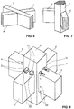
- FIG. 1 a crossing point is shown in which two superimposed vertical supports a, b from opposite sides to a continuous, horizontal bar g abut.
- the support b forms the continuation of the support a upwards.
- FIG. 4 shows an inner crossing point, as it often occurs especially in skeleton.
- the carrier e forms on the opposite side of the support a, the continuation of the carrier c in the longitudinal direction.
- the support f on the side of the support a opposite the support d forms the continuation of the support d in its longitudinal direction.
- FIG. 5 a continuous horizontal support c is shown, on which from two opposite sides two further horizontal support e and d abut.
- the carrier e forms on the opposite side of the carrier c, the continuation of the carrier d in the longitudinal direction.
- FIG. 6 shows the same situation as the FIG. 5 , wherein here, however, the carriers e and d each extend inclined to the longitudinal direction of the continuous carrier c.
- FIG. 7 shows a vertical corner support a, on which abut two horizontal support c and d.
- the two carriers c and d extend in mutually perpendicular directions. With respect to the respective longitudinal directions of the carriers c and d, the end faces of the carriers c and d resting on the support a are bevelled.
- the inventive connection arrangement can in each of the in the FIGS. 1 to 7 illustrated situations are used to achieve a solid and in particular rigid connection of the respective timber components ai in the illustrated crossing points.
- FIG. 8 an inventive connection arrangement is exemplary for the case of the situation of FIG. 4 shown.
- the FIG. 18 shows the same connection arrangement as the FIG. 4 However, the wood components a, c, d, e, f are omitted for illustrative reasons.
- FIGS. 8 and 18 In a synopsis of FIGS. 8 and 18 is clearly visible that the carrier d and f are attached by means of two juxtaposed, identically formed connecting devices on the support a.
- the carriers c and e are also attached to the support a by means of two juxtaposed, identically designed connecting devices.
- four connecting devices are thus provided here, each of which together with the corresponding carriers c and e or d and f and with the support a forms a connection arrangement according to the invention.
- a single connection device of the carriers d and f is in the FIG. 10 and a single connecting device of the carriers c and e in the FIG. 15 ,
- the connecting device of the carrier d and f on the one hand and the connecting devices of the carrier c and e on the other hand differ from each other in terms of their design, in particular what the connecting parts 3 and 4 As.
- both the connection devices of the carrier d and f and those of the carrier c and e each have power transmission elements 1, which pass through the support a, that is, extend transversely through the support a through.
- the power transmission elements 1 of the connecting devices of the carrier d and f differ only in terms of their number and diameter, but not with respect to their basic design, of those of the connecting devices of the carrier c and e.
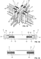
- FIG. 9 one of the fixed in the support a power transmission elements 1 is shown.
- the power transmission element 1 shown in this figure could belong to both one of the connection devices of the carriers c and e and to one of the connection devices of the carriers d and f.
- the power transmission element 1 extends transversely through the support a therethrough.
- the power transmission element 1 has two end regions 11 and 12, which come to rest flush with their end surfaces with the outer surface of the support a.
- the length of the power transmission element 1 thus corresponds almost exactly to the thickness of the support a.
- the rod-shaped power transmission element 1 has in both end regions 11 and 12 each have a blind hole-like axial bore, which forms in each case a sleeve-shaped region of the force transmission element 1.
- the blind hole-like bores each have an internal thread 13.
- the internal threads 13 extend in the longitudinal direction of the power transmission element 1 but not quite to the respective end face of the power transmission element 1, but ends at a distance thereto.
- a thread-free portion 14 of the blind hole-like bore is present in each case, which has a larger diameter compared to the provided with the internal thread 13 portion of the bore.
- the force transmission element 1 has a solid cross-section. Except for the internal thread 13, the power transmission element 1 as a whole has a completely rotationally symmetrical shape.
- the power transmission element 1 is inserted in a transverse bore of the wooden component a and fixed in a rigid manner. In order to achieve a shear-resistant fixation, the power transmission element 1 is glued in the wood component a.
- an adhesive is introduced between the outer surface of the force transmission element 1 and the inner surface of the transverse bore of the wooden component a.
- the adhesive may in particular be an epoxy resin.
- the outer surface of the force transmission element 1 may have an outer structure with local elevations and / or depressions, such as in particular a groove-shaped outer structure.
- the outer structure preferably extends along the entire longitudinal extent of the force transmission element 1. In this way, an extremely strong and very rigid mounting of the force transmission element 1 in the timber component can be achieved.
- cross members extending transversely to the force transmission elements 1 may be provided in the wooden component in the vicinity of the force transmission elements 1.
- the cross bars are not shown in the figures.
- the transverse rods are arranged directly below the power transmission elements 1, in particular to be able to distribute weight forces regularly on the wooden component.
- the cross bars are preferably glued similar to the power transmission elements 1 in the timber component.
- the connecting devices in the FIG. 8 shown carrier d and f according to FIG. 18 Each having two such power transmission elements 1 with a relatively large diameter, the connecting devices of the carrier c and e each have four such power transmission elements 1 with a slightly smaller diameter compared to it.
- connection devices of the carrier d and f based on FIGS. 10 to 14 and the configuration of the connecting devices of the carrier c and e on the basis of FIGS. 15 to 17 explained in more detail.
- the connecting device of FIG. 10 has two strip-shaped connection parts 3, which are each anchored with a plurality of anchor rods 33 in the respective carrier d or f. Specifically, five anchor rods 33 are provided per connector part 3 here. In order to achieve a powerful attachment of the anchor rods 33 in the respective timber component, they have a groove-shaped outer structure, not shown in the figures, which extends in each case over the entire longitudinal extent of the anchor rods 33. By means of an adhesive, in particular an epoxy resin, the anchor rods 33 are glued in the respective wooden component. The number and the directions and the dimensions of the anchor rods 33 can be varied depending on the expected forces. In the in the FIG.
- two upper and two lower anchor rods 33 are respectively provided, which are attached to each of the connecting parts 3 and each extending perpendicular to their longitudinal directions in the wooden member b inside.
- a fifth anchor rod 33 which is fastened between the two upper and two lower anchor rods 33 on the respective attachment part 3, extends in each case inclined to these and to the longitudinal direction of the attachment part 3 into the wooden component b.
- the fifth anchor rod 33 is arranged in the same plane as the two upper and two lower anchor rods 33.
- connection parts 3 of the FIG. 10 Ways are each formed solid and have a rectangular cross-section. In the longitudinal direction they are slightly longer than the thickness of the carrier d and f in the appropriate direction. As a result, the connection parts 3 each have an end region 31 that projects beyond the supports d and f at the top (see FIG FIG. 8 ). In this end region 31, a through bore 32 is provided, which serves for fastening of the connection part 3 on the force transmission element 1. For this purpose, a screw not shown in the figures is screwed through the bore 32 into the internal thread 13 of the power transmission element 1. Characterized in that the bore 32 is arranged in the projecting region 31, good accessibility for screwing the screw is ensured.
- an undercut 35 is provided in each case, which in particular in the FIGS. 12 to 14 is clearly recognizable.
- the undercut 35 is formed laterally open, wherein the opening disposed within the end face of the end portion 34 is.
- the undercut 35 can be engaged behind by a cam 21 of a screw 2. As it is in particular in the FIGS. 13 and 14 is clearly visible, the undercut 35 forms a stop element for the screw 2, which prevents withdrawal of the screw 2 in a direction perpendicular to the longitudinal direction of the terminal block 3 extending direction.
- the screw 2 rests with the cam 21 but not only on the undercut 35, but also on the opposite to the undercut 35 arranged solidly formed part of the end portion 34.
- the screw 2 is thereby perpendicular to the longitudinal direction of the terminal block 3 fixed in the terminal block. 3 held, whereby both tensile and compressive forces acting on the screw 2, are transmitted directly to the terminal block.
- lateral recesses 36 can be provided in the side surfaces of the connecting part 3 that are perpendicular to the end face (see in particular FIGS FIGS. 12 and 13 ) to facilitate insertion of the cam 21 behind the undercut 35. Due to the recesses 36, the cam 21 can be inserted not only perpendicular to the end face of the end portion 34 behind the undercut 35, but also from inclined to standing directions.
- the undercut 35 is formed in this case in the region of the end face by two mutually parallel webs.
- the screw 2 is, as in the FIG. 11 is shown screwed with its shaft 23 formed on the external thread into the internal thread 13 of the power transmission element 1.
- the screw 2 thus forms a connecting element for connecting the power transmission element 1 to the terminal block.
- the screw 2 between the cam 21, which forms the screw head, and the shaft 23, a thread-free portion 22 which has a larger diameter compared to the shaft 23.
- the outer diameter of the unthreaded portion 22 of the screw 2 corresponds approximately to the inner diameter of the unthreaded portion 14 of the power transmission element 1.
- the terminal strips 3 are preferably preassembled on the respective timber components.
- the power transmission elements 1 are advantageous already in the pre-assembly shear-resistant bonded in the corresponding wooden component and screwed the screws 2 in this.
- the final assembly of the wooden components at the intended installation location is then particularly easy:
- the in the FIG. 8 shown support d, f can be hooked with the downwardly open undercuts 35 of the terminal strips 3 simply from above into the protruding on the support a cam 21 of the screwed into the power transmission elements 1 2 screws.
- the carriers d, f are thus already in a stable position. Subsequently, the carrier d, f by means of screws which are screwed through the holes 32 of the terminal strips 3 into the internal thread 13 of the power transmission element 1, finally fixed to the support.
- connection device shown has connection parts 4, which are anchored in each case by means of anchor rods 42 attached thereto in one of the carrier c or e.
- the tie rods 42 of which four are provided in the present case, are preferably glued in the respective timber component.
- the tie rods 42 may each have an outer structure with local elevations and / or depressions, in particular a groove-shaped outer structure. Depending on the expected forces, the number and the direction and dimensioning of the tie rods can be varied.
- the connection parts 4 each have a groove 41.
- connection parts 5 are attached to the respective end regions 11 and 12 of the force transmission elements 1 and thus to the support 1.
- anchor rods 53 are mounted, which are fixed in the sleeve-shaped end portions 11, 12 of the power transmission elements 1.
- the anchor rods 42 can each have an external thread, which can be screwed into the internal thread 13 of the force transmission element 1.
- the anchor rods 53 are preferred by means of an adhesive 6 in the sleeve-shaped end portions 11, 12 of the Power transmission elements 1 glued (see FIGS. 16 and 17 ).
- the anchor rods may have an outer structure with local elevations and / or depressions, such as, in particular, a groove-shaped outer structure in order to reinforce the connection to the force transmission elements 1.
- lateral injection bores may be provided in the force transmission elements 1 and in the wooden component a.
- the connecting parts 5 also each have a comb 51.
- connection parts 5 In order to fix the carriers c and e to the support a, the comb 51 of the connection parts 5 are respectively pushed into the grooves 41 of the connection parts 4. The fixation then takes place by means of transverse bolts 52, which are used in mutually aligned transverse bores of the connecting parts 4 and 5 in the region of the comb / groove connection.
- the connecting parts 4 and 5 correspond in particular to those in the EP 1 736 606 A1 already disclosed, the contents of which are hereby incorporated in full in the application.
- connection parts 4 and the connection parts 5 can each already be preassembled in the respective wooden components c, e or a.
- FIG. 10 While in the FIG. 10 shown connecting device by means of hooking and then screwing a particularly simple final assembly allows, which is in the FIG. 15 shown connecting device by means of varying the number, direction and dimensions of the anchor rods 53 and accordingly the power transmission elements 1 optimally adapted to the expected forces.
- all the power transmission elements 1 can be arranged immediately adjacent to the end face of the respective carrier c or e, so that a continuous, in particular rectilinear flow of force from the carrier c via the power transmission elements 1 to the carrier e and in the reverse direction is ensured.
- the force flow is led out of the carrier f or d via the projecting region 31, so that no linear force flow results anymore.
- connection devices of the carriers f, d allow a very simple assembly
- the anchoring rods 53 and the power transmission elements 1 of the connection devices of the carriers c, e can be easily arranged outside the force transmission elements 1 of the connection devices of the carriers d, f.
- the carriers c, e and the carriers d, f can all be fastened to the support a at the same height.
- the connecting devices for the viewer are largely invisible housed within the timber components a, c, d, e, f.
- the bolts 52 and the side surfaces of the connecting parts 4 and 5, which are visible, can optionally be covered, for example, by wood inserts.
- FIGS. 19 and 20 alternative embodiments of the screws 2 and the power transmission element 1 shown.
- the screws 2 can, as it is in the FIG. 19 is also shown to have a thread-free portion 22 which has the same diameter as the shaft 23.
- the thread of the shaft 23 may also extend over the portion 22 to the cam 21.
- the screws 2 instead of the screws 2 to provide connecting elements which each have a cam 21, but which have no thread, but by means of an adhesive, similar to the anchor rods 53, are mounted in the power transmission element 1.
- Power transmission element 1 may also be formed sleeve-shaped as a whole, with a through opening, which may be limited along its entire length by an internal thread. A variety of other modifications is conceivable.
Landscapes
- Engineering & Computer Science (AREA)
- Architecture (AREA)
- Physics & Mathematics (AREA)
- Electromagnetism (AREA)
- Civil Engineering (AREA)
- Structural Engineering (AREA)
- Joining Of Building Structures In Genera (AREA)
Priority Applications (1)
| Application Number | Priority Date | Filing Date | Title |
|---|---|---|---|
| EP16157291.2A EP3211146B1 (fr) | 2016-02-25 | 2016-02-25 | Systeme de liaison pour une construction en bois |
Applications Claiming Priority (1)
| Application Number | Priority Date | Filing Date | Title |
|---|---|---|---|
| EP16157291.2A EP3211146B1 (fr) | 2016-02-25 | 2016-02-25 | Systeme de liaison pour une construction en bois |
Publications (2)
| Publication Number | Publication Date |
|---|---|
| EP3211146A1 true EP3211146A1 (fr) | 2017-08-30 |
| EP3211146B1 EP3211146B1 (fr) | 2020-05-20 |
Family
ID=55451036
Family Applications (1)
| Application Number | Title | Priority Date | Filing Date |
|---|---|---|---|
| EP16157291.2A Active EP3211146B1 (fr) | 2016-02-25 | 2016-02-25 | Systeme de liaison pour une construction en bois |
Country Status (1)
| Country | Link |
|---|---|
| EP (1) | EP3211146B1 (fr) |
Cited By (1)
| Publication number | Priority date | Publication date | Assignee | Title |
|---|---|---|---|---|
| WO2024235955A1 (fr) * | 2023-05-15 | 2024-11-21 | n'H Holding AG Lungern | Ensemble de raccordement permettant de relier des parties de structure de support d'une structure de support |
Families Citing this family (1)
| Publication number | Priority date | Publication date | Assignee | Title |
|---|---|---|---|---|
| CA3212273A1 (fr) | 2021-03-29 | 2022-10-06 | Bruno Zumbrunn-Maurer | Ensemble de liaison pour relier deux composants dans le domaine de la construction |
Citations (6)
| Publication number | Priority date | Publication date | Assignee | Title |
|---|---|---|---|---|
| DE3516423A1 (de) * | 1984-05-03 | 1985-11-07 | Multikunst Design ApS, Ringe | Verfahren zur herstellung einer stabilisierten bolzenverbindung zwischen einem holzelement und einem anderen konstruktionselement sowie verbindungselement |
| JP2000234393A (ja) * | 1999-02-12 | 2000-08-29 | Kuretetsuku Kk | 建築物の接合金具 |
| JP2000265553A (ja) * | 1999-03-18 | 2000-09-26 | Mitsui Home Co Ltd | 木質部材の接合構造 |
| KR20060102785A (ko) | 2005-03-25 | 2006-09-28 | 유승룡 | 철근 볼트 접합에 의한 프리캐스트 콘크리트 기둥과 보의건식 연결부 개발 |
| EP1736606A1 (fr) | 2005-06-23 | 2006-12-27 | Neue Holzbau AG Lungern | Assemblage résistante à la flexion et enfichable pour éléments de construction |
| ES2387852A1 (es) | 2010-12-22 | 2012-10-02 | Imat Centre Tecnològic De La Construcció | Viga armada con redondos destinada a ser unida por atornillado a un pilar, sistema de unión de dicha viga con un pilar, y estructura provista de dicho sistema. |
Family Cites Families (1)
| Publication number | Priority date | Publication date | Assignee | Title |
|---|---|---|---|---|
| JPH10204988A (ja) * | 1997-01-23 | 1998-08-04 | Iezukuri Kobo:Kk | 柱と土台の接合装置 |
-
2016
- 2016-02-25 EP EP16157291.2A patent/EP3211146B1/fr active Active
Patent Citations (6)
| Publication number | Priority date | Publication date | Assignee | Title |
|---|---|---|---|---|
| DE3516423A1 (de) * | 1984-05-03 | 1985-11-07 | Multikunst Design ApS, Ringe | Verfahren zur herstellung einer stabilisierten bolzenverbindung zwischen einem holzelement und einem anderen konstruktionselement sowie verbindungselement |
| JP2000234393A (ja) * | 1999-02-12 | 2000-08-29 | Kuretetsuku Kk | 建築物の接合金具 |
| JP2000265553A (ja) * | 1999-03-18 | 2000-09-26 | Mitsui Home Co Ltd | 木質部材の接合構造 |
| KR20060102785A (ko) | 2005-03-25 | 2006-09-28 | 유승룡 | 철근 볼트 접합에 의한 프리캐스트 콘크리트 기둥과 보의건식 연결부 개발 |
| EP1736606A1 (fr) | 2005-06-23 | 2006-12-27 | Neue Holzbau AG Lungern | Assemblage résistante à la flexion et enfichable pour éléments de construction |
| ES2387852A1 (es) | 2010-12-22 | 2012-10-02 | Imat Centre Tecnològic De La Construcció | Viga armada con redondos destinada a ser unida por atornillado a un pilar, sistema de unión de dicha viga con un pilar, y estructura provista de dicho sistema. |
Cited By (1)
| Publication number | Priority date | Publication date | Assignee | Title |
|---|---|---|---|---|
| WO2024235955A1 (fr) * | 2023-05-15 | 2024-11-21 | n'H Holding AG Lungern | Ensemble de raccordement permettant de relier des parties de structure de support d'une structure de support |
Also Published As
| Publication number | Publication date |
|---|---|
| EP3211146B1 (fr) | 2020-05-20 |
Similar Documents
| Publication | Publication Date | Title |
|---|---|---|
| EP2212483B1 (fr) | Structure porteuse | |
| EP1863980A2 (fr) | Clavette pour relier au moins deux elements de construction, et systeme d'elements de construction relies les uns aux autres | |
| EP3433440B1 (fr) | Procédé d'assemblage de poutres en bois | |
| DE102013109845A1 (de) | Lager für eine Unterkonstruktion, beispielsweise einer Terrasse | |
| DE102005044980B4 (de) | Stoßverbinder für Holz-/Aluminiumfassaden | |
| EP1216332B1 (fr) | Systeme de liaison destine a la fixation rigide d'au moins deux elements | |
| DE102016103774B4 (de) | Verbindungsanordnung, Verbindungselement zur Verwendung in einer Verbindungsanordnung und Montageverfahren zur Herstellung einer Verbindungsanordnung | |
| EP3211146B1 (fr) | Systeme de liaison pour une construction en bois | |
| DE19757905A1 (de) | Wandungssystem, insbesondere für Messehallen | |
| EP0988430B1 (fr) | Panne de couplage constituee de deux ou plusieurs poutres en bois jointes l'une a l'autre par chevauchement longitudinal, ainsi qu'element de fixation pour relier deux zones d'extremite se chevauchant de poutres en bois a utiliser pour une panne de couplage | |
| DE20003705U1 (de) | Verbindung von zwei zumindest annähernd rechtwinklig aneinander anschließenden Holzbalken | |
| DE102006024440B4 (de) | Schraubanker | |
| EP3586614B1 (fr) | Systeme de connection pour meuble modulaire ou stand de foire | |
| DE202004014808U1 (de) | Baukasten zum Erstellen einer Halterung, insbesondere für Rohrleitungen | |
| EP4459073A1 (fr) | Renforcement pour un support de béton poreux, support de béton poreux, utilisation d'un support de béton poreux, procédé de renforcement d'un support de béton poreux et utilisation d'un renforcement | |
| WO2022207346A1 (fr) | Ensemble de liaison pour relier deux composants dans le domaine de la construction | |
| EP1736606B1 (fr) | Assemblage rigide ou articulée et enfichable pour éléments de construction | |
| DE102011015495B4 (de) | Befestigungsanordnung und Verfahren zur Herstellung einer solchen | |
| DE20306942U1 (de) | System miteinander verbundener Bauelemente | |
| EP2458229A1 (fr) | Dispositif de connexion | |
| WO2008151716A2 (fr) | Système de meuble et meuble | |
| DE20120208U1 (de) | Verbindung von aus Holzbalken oder -Latten bestehenden Pfosten und Riegeln zur Bildung von Wandelementen | |
| DE102004055556B4 (de) | Verbindungselement für Profile | |
| EP1605172B1 (fr) | Ferrure pour assembler un élément structural allongé et un élément structural plat | |
| DE20119279U1 (de) | Verankerungsstelle zur Befestigung von flachen Verbindungsbauteilen in aushärtenden Baustoffen |
Legal Events
| Date | Code | Title | Description |
|---|---|---|---|
| PUAI | Public reference made under article 153(3) epc to a published international application that has entered the european phase |
Free format text: ORIGINAL CODE: 0009012 |
|
| STAA | Information on the status of an ep patent application or granted ep patent |
Free format text: STATUS: THE APPLICATION HAS BEEN PUBLISHED |
|
| AK | Designated contracting states |
Kind code of ref document: A1 Designated state(s): AL AT BE BG CH CY CZ DE DK EE ES FI FR GB GR HR HU IE IS IT LI LT LU LV MC MK MT NL NO PL PT RO RS SE SI SK SM TR |
|
| AX | Request for extension of the european patent |
Extension state: BA ME |
|
| STAA | Information on the status of an ep patent application or granted ep patent |
Free format text: STATUS: REQUEST FOR EXAMINATION WAS MADE |
|
| 17P | Request for examination filed |
Effective date: 20180111 |
|
| RBV | Designated contracting states (corrected) |
Designated state(s): AL AT BE BG CH CY CZ DE DK EE ES FI FR GB GR HR HU IE IS IT LI LT LU LV MC MK MT NL NO PL PT RO RS SE SI SK SM TR |
|
| GRAP | Despatch of communication of intention to grant a patent |
Free format text: ORIGINAL CODE: EPIDOSNIGR1 |
|
| STAA | Information on the status of an ep patent application or granted ep patent |
Free format text: STATUS: GRANT OF PATENT IS INTENDED |
|
| INTG | Intention to grant announced |
Effective date: 20191211 |
|
| GRAS | Grant fee paid |
Free format text: ORIGINAL CODE: EPIDOSNIGR3 |
|
| GRAA | (expected) grant |
Free format text: ORIGINAL CODE: 0009210 |
|
| STAA | Information on the status of an ep patent application or granted ep patent |
Free format text: STATUS: THE PATENT HAS BEEN GRANTED |
|
| AK | Designated contracting states |
Kind code of ref document: B1 Designated state(s): AL AT BE BG CH CY CZ DE DK EE ES FI FR GB GR HR HU IE IS IT LI LT LU LV MC MK MT NL NO PL PT RO RS SE SI SK SM TR |
|
| REG | Reference to a national code |
Ref country code: GB Ref legal event code: FG4D Free format text: NOT ENGLISH |
|
| REG | Reference to a national code |
Ref country code: CH Ref legal event code: NV Representative=s name: ISLER AND PEDRAZZINI AG, CH Ref country code: CH Ref legal event code: EP |
|
| REG | Reference to a national code |
Ref country code: DE Ref legal event code: R096 Ref document number: 502016009977 Country of ref document: DE |
|
| REG | Reference to a national code |
Ref country code: AT Ref legal event code: REF Ref document number: 1272681 Country of ref document: AT Kind code of ref document: T Effective date: 20200615 |
|
| REG | Reference to a national code |
Ref country code: NO Ref legal event code: T2 Effective date: 20200520 |
|
| REG | Reference to a national code |
Ref country code: LT Ref legal event code: MG4D |
|
| REG | Reference to a national code |
Ref country code: NL Ref legal event code: MP Effective date: 20200520 |
|
| PG25 | Lapsed in a contracting state [announced via postgrant information from national office to epo] |
Ref country code: FI Free format text: LAPSE BECAUSE OF FAILURE TO SUBMIT A TRANSLATION OF THE DESCRIPTION OR TO PAY THE FEE WITHIN THE PRESCRIBED TIME-LIMIT Effective date: 20200520 Ref country code: IS Free format text: LAPSE BECAUSE OF FAILURE TO SUBMIT A TRANSLATION OF THE DESCRIPTION OR TO PAY THE FEE WITHIN THE PRESCRIBED TIME-LIMIT Effective date: 20200920 Ref country code: PT Free format text: LAPSE BECAUSE OF FAILURE TO SUBMIT A TRANSLATION OF THE DESCRIPTION OR TO PAY THE FEE WITHIN THE PRESCRIBED TIME-LIMIT Effective date: 20200921 Ref country code: LT Free format text: LAPSE BECAUSE OF FAILURE TO SUBMIT A TRANSLATION OF THE DESCRIPTION OR TO PAY THE FEE WITHIN THE PRESCRIBED TIME-LIMIT Effective date: 20200520 Ref country code: GR Free format text: LAPSE BECAUSE OF FAILURE TO SUBMIT A TRANSLATION OF THE DESCRIPTION OR TO PAY THE FEE WITHIN THE PRESCRIBED TIME-LIMIT Effective date: 20200821 Ref country code: SE Free format text: LAPSE BECAUSE OF FAILURE TO SUBMIT A TRANSLATION OF THE DESCRIPTION OR TO PAY THE FEE WITHIN THE PRESCRIBED TIME-LIMIT Effective date: 20200520 |
|
| PG25 | Lapsed in a contracting state [announced via postgrant information from national office to epo] |
Ref country code: BG Free format text: LAPSE BECAUSE OF FAILURE TO SUBMIT A TRANSLATION OF THE DESCRIPTION OR TO PAY THE FEE WITHIN THE PRESCRIBED TIME-LIMIT Effective date: 20200820 Ref country code: RS Free format text: LAPSE BECAUSE OF FAILURE TO SUBMIT A TRANSLATION OF THE DESCRIPTION OR TO PAY THE FEE WITHIN THE PRESCRIBED TIME-LIMIT Effective date: 20200520 Ref country code: HR Free format text: LAPSE BECAUSE OF FAILURE TO SUBMIT A TRANSLATION OF THE DESCRIPTION OR TO PAY THE FEE WITHIN THE PRESCRIBED TIME-LIMIT Effective date: 20200520 Ref country code: LV Free format text: LAPSE BECAUSE OF FAILURE TO SUBMIT A TRANSLATION OF THE DESCRIPTION OR TO PAY THE FEE WITHIN THE PRESCRIBED TIME-LIMIT Effective date: 20200520 |
|
| PG25 | Lapsed in a contracting state [announced via postgrant information from national office to epo] |
Ref country code: NL Free format text: LAPSE BECAUSE OF FAILURE TO SUBMIT A TRANSLATION OF THE DESCRIPTION OR TO PAY THE FEE WITHIN THE PRESCRIBED TIME-LIMIT Effective date: 20200520 Ref country code: AL Free format text: LAPSE BECAUSE OF FAILURE TO SUBMIT A TRANSLATION OF THE DESCRIPTION OR TO PAY THE FEE WITHIN THE PRESCRIBED TIME-LIMIT Effective date: 20200520 |
|
| PG25 | Lapsed in a contracting state [announced via postgrant information from national office to epo] |
Ref country code: DK Free format text: LAPSE BECAUSE OF FAILURE TO SUBMIT A TRANSLATION OF THE DESCRIPTION OR TO PAY THE FEE WITHIN THE PRESCRIBED TIME-LIMIT Effective date: 20200520 Ref country code: IT Free format text: LAPSE BECAUSE OF FAILURE TO SUBMIT A TRANSLATION OF THE DESCRIPTION OR TO PAY THE FEE WITHIN THE PRESCRIBED TIME-LIMIT Effective date: 20200520 Ref country code: SM Free format text: LAPSE BECAUSE OF FAILURE TO SUBMIT A TRANSLATION OF THE DESCRIPTION OR TO PAY THE FEE WITHIN THE PRESCRIBED TIME-LIMIT Effective date: 20200520 Ref country code: EE Free format text: LAPSE BECAUSE OF FAILURE TO SUBMIT A TRANSLATION OF THE DESCRIPTION OR TO PAY THE FEE WITHIN THE PRESCRIBED TIME-LIMIT Effective date: 20200520 Ref country code: ES Free format text: LAPSE BECAUSE OF FAILURE TO SUBMIT A TRANSLATION OF THE DESCRIPTION OR TO PAY THE FEE WITHIN THE PRESCRIBED TIME-LIMIT Effective date: 20200520 Ref country code: RO Free format text: LAPSE BECAUSE OF FAILURE TO SUBMIT A TRANSLATION OF THE DESCRIPTION OR TO PAY THE FEE WITHIN THE PRESCRIBED TIME-LIMIT Effective date: 20200520 Ref country code: CZ Free format text: LAPSE BECAUSE OF FAILURE TO SUBMIT A TRANSLATION OF THE DESCRIPTION OR TO PAY THE FEE WITHIN THE PRESCRIBED TIME-LIMIT Effective date: 20200520 |
|
| REG | Reference to a national code |
Ref country code: DE Ref legal event code: R097 Ref document number: 502016009977 Country of ref document: DE |
|
| PG25 | Lapsed in a contracting state [announced via postgrant information from national office to epo] |
Ref country code: PL Free format text: LAPSE BECAUSE OF FAILURE TO SUBMIT A TRANSLATION OF THE DESCRIPTION OR TO PAY THE FEE WITHIN THE PRESCRIBED TIME-LIMIT Effective date: 20200520 Ref country code: SK Free format text: LAPSE BECAUSE OF FAILURE TO SUBMIT A TRANSLATION OF THE DESCRIPTION OR TO PAY THE FEE WITHIN THE PRESCRIBED TIME-LIMIT Effective date: 20200520 |
|
| PLBE | No opposition filed within time limit |
Free format text: ORIGINAL CODE: 0009261 |
|
| STAA | Information on the status of an ep patent application or granted ep patent |
Free format text: STATUS: NO OPPOSITION FILED WITHIN TIME LIMIT |
|
| 26N | No opposition filed |
Effective date: 20210223 |
|
| PG25 | Lapsed in a contracting state [announced via postgrant information from national office to epo] |
Ref country code: SI Free format text: LAPSE BECAUSE OF FAILURE TO SUBMIT A TRANSLATION OF THE DESCRIPTION OR TO PAY THE FEE WITHIN THE PRESCRIBED TIME-LIMIT Effective date: 20200520 |
|
| PG25 | Lapsed in a contracting state [announced via postgrant information from national office to epo] |
Ref country code: MC Free format text: LAPSE BECAUSE OF FAILURE TO SUBMIT A TRANSLATION OF THE DESCRIPTION OR TO PAY THE FEE WITHIN THE PRESCRIBED TIME-LIMIT Effective date: 20200520 |
|
| REG | Reference to a national code |
Ref country code: BE Ref legal event code: MM Effective date: 20210228 |
|
| PG25 | Lapsed in a contracting state [announced via postgrant information from national office to epo] |
Ref country code: LU Free format text: LAPSE BECAUSE OF NON-PAYMENT OF DUE FEES Effective date: 20210225 |
|
| PG25 | Lapsed in a contracting state [announced via postgrant information from national office to epo] |
Ref country code: FR Free format text: LAPSE BECAUSE OF NON-PAYMENT OF DUE FEES Effective date: 20210228 Ref country code: IE Free format text: LAPSE BECAUSE OF NON-PAYMENT OF DUE FEES Effective date: 20210225 |
|
| REG | Reference to a national code |
Ref country code: AT Ref legal event code: MM01 Ref document number: 1272681 Country of ref document: AT Kind code of ref document: T Effective date: 20210225 |
|
| PG25 | Lapsed in a contracting state [announced via postgrant information from national office to epo] |
Ref country code: AT Free format text: LAPSE BECAUSE OF NON-PAYMENT OF DUE FEES Effective date: 20210225 |
|
| PG25 | Lapsed in a contracting state [announced via postgrant information from national office to epo] |
Ref country code: BE Free format text: LAPSE BECAUSE OF NON-PAYMENT OF DUE FEES Effective date: 20210228 |
|
| PG25 | Lapsed in a contracting state [announced via postgrant information from national office to epo] |
Ref country code: HU Free format text: LAPSE BECAUSE OF FAILURE TO SUBMIT A TRANSLATION OF THE DESCRIPTION OR TO PAY THE FEE WITHIN THE PRESCRIBED TIME-LIMIT; INVALID AB INITIO Effective date: 20160225 |
|
| PG25 | Lapsed in a contracting state [announced via postgrant information from national office to epo] |
Ref country code: CY Free format text: LAPSE BECAUSE OF FAILURE TO SUBMIT A TRANSLATION OF THE DESCRIPTION OR TO PAY THE FEE WITHIN THE PRESCRIBED TIME-LIMIT Effective date: 20200520 |
|
| P01 | Opt-out of the competence of the unified patent court (upc) registered |
Effective date: 20230630 |
|
| PG25 | Lapsed in a contracting state [announced via postgrant information from national office to epo] |
Ref country code: MK Free format text: LAPSE BECAUSE OF FAILURE TO SUBMIT A TRANSLATION OF THE DESCRIPTION OR TO PAY THE FEE WITHIN THE PRESCRIBED TIME-LIMIT Effective date: 20200520 |
|
| PG25 | Lapsed in a contracting state [announced via postgrant information from national office to epo] |
Ref country code: TR Free format text: LAPSE BECAUSE OF FAILURE TO SUBMIT A TRANSLATION OF THE DESCRIPTION OR TO PAY THE FEE WITHIN THE PRESCRIBED TIME-LIMIT Effective date: 20200520 |
|
| PG25 | Lapsed in a contracting state [announced via postgrant information from national office to epo] |
Ref country code: MT Free format text: LAPSE BECAUSE OF FAILURE TO SUBMIT A TRANSLATION OF THE DESCRIPTION OR TO PAY THE FEE WITHIN THE PRESCRIBED TIME-LIMIT Effective date: 20200520 |
|
| PGFP | Annual fee paid to national office [announced via postgrant information from national office to epo] |
Ref country code: CH Payment date: 20250301 Year of fee payment: 10 |
|
| REG | Reference to a national code |
Ref country code: DE Ref legal event code: R082 Ref document number: 502016009977 Country of ref document: DE Representative=s name: TERGAU & WALKENHORST INTELLECTUAL PROPERTY GMB, DE |
|
| REG | Reference to a national code |
Ref country code: CH Ref legal event code: U11 Free format text: ST27 STATUS EVENT CODE: U-0-0-U10-U11 (AS PROVIDED BY THE NATIONAL OFFICE) Effective date: 20260301 |
|
| PGFP | Annual fee paid to national office [announced via postgrant information from national office to epo] |
Ref country code: GB Payment date: 20260219 Year of fee payment: 11 |
|
| PGFP | Annual fee paid to national office [announced via postgrant information from national office to epo] |
Ref country code: NO Payment date: 20260220 Year of fee payment: 11 Ref country code: DE Payment date: 20260218 Year of fee payment: 11 |