EP3211293B1 - Vorrichtung zur wärmeableitung für eine leuchtvorrichtung eines kraftfahrzeugs - Google Patents
Vorrichtung zur wärmeableitung für eine leuchtvorrichtung eines kraftfahrzeugs Download PDFInfo
- Publication number
- EP3211293B1 EP3211293B1 EP17156709.2A EP17156709A EP3211293B1 EP 3211293 B1 EP3211293 B1 EP 3211293B1 EP 17156709 A EP17156709 A EP 17156709A EP 3211293 B1 EP3211293 B1 EP 3211293B1
- Authority
- EP
- European Patent Office
- Prior art keywords
- printed circuit
- metal support
- crimping
- heat dissipation
- support
- Prior art date
- Legal status (The legal status is an assumption and is not a legal conclusion. Google has not performed a legal analysis and makes no representation as to the accuracy of the status listed.)
- Active
Links
Images
Classifications
-
- F—MECHANICAL ENGINEERING; LIGHTING; HEATING; WEAPONS; BLASTING
- F21—LIGHTING
- F21S—NON-PORTABLE LIGHTING DEVICES; SYSTEMS THEREOF; VEHICLE LIGHTING DEVICES SPECIALLY ADAPTED FOR VEHICLE EXTERIORS
- F21S45/00—Arrangements within vehicle lighting devices specially adapted for vehicle exteriors, for purposes other than emission or distribution of light
- F21S45/40—Cooling of lighting devices
- F21S45/47—Passive cooling, e.g. using fins, thermal conductive elements or openings
-
- F—MECHANICAL ENGINEERING; LIGHTING; HEATING; WEAPONS; BLASTING
- F21—LIGHTING
- F21S—NON-PORTABLE LIGHTING DEVICES; SYSTEMS THEREOF; VEHICLE LIGHTING DEVICES SPECIALLY ADAPTED FOR VEHICLE EXTERIORS
- F21S41/00—Illuminating devices specially adapted for vehicle exteriors, e.g. headlamps
- F21S41/10—Illuminating devices specially adapted for vehicle exteriors, e.g. headlamps characterised by the light source
- F21S41/19—Attachment of light sources or lamp holders
- F21S41/192—Details of lamp holders, terminals or connectors
-
- F—MECHANICAL ENGINEERING; LIGHTING; HEATING; WEAPONS; BLASTING
- F21—LIGHTING
- F21S—NON-PORTABLE LIGHTING DEVICES; SYSTEMS THEREOF; VEHICLE LIGHTING DEVICES SPECIALLY ADAPTED FOR VEHICLE EXTERIORS
- F21S45/00—Arrangements within vehicle lighting devices specially adapted for vehicle exteriors, for purposes other than emission or distribution of light
- F21S45/40—Cooling of lighting devices
- F21S45/49—Attachment of the cooling means
-
- F—MECHANICAL ENGINEERING; LIGHTING; HEATING; WEAPONS; BLASTING
- F21—LIGHTING
- F21S—NON-PORTABLE LIGHTING DEVICES; SYSTEMS THEREOF; VEHICLE LIGHTING DEVICES SPECIALLY ADAPTED FOR VEHICLE EXTERIORS
- F21S45/00—Arrangements within vehicle lighting devices specially adapted for vehicle exteriors, for purposes other than emission or distribution of light
- F21S45/50—Waterproofing
-
- F—MECHANICAL ENGINEERING; LIGHTING; HEATING; WEAPONS; BLASTING
- F21—LIGHTING
- F21V—FUNCTIONAL FEATURES OR DETAILS OF LIGHTING DEVICES OR SYSTEMS THEREOF; STRUCTURAL COMBINATIONS OF LIGHTING DEVICES WITH OTHER ARTICLES, NOT OTHERWISE PROVIDED FOR
- F21V17/00—Fastening of component parts of lighting devices, e.g. shades, globes, refractors, reflectors, filters, screens, grids or protective cages
- F21V17/10—Fastening of component parts of lighting devices, e.g. shades, globes, refractors, reflectors, filters, screens, grids or protective cages characterised by specific fastening means or way of fastening
- F21V17/14—Bayonet-type fastening
-
- F—MECHANICAL ENGINEERING; LIGHTING; HEATING; WEAPONS; BLASTING
- F21—LIGHTING
- F21V—FUNCTIONAL FEATURES OR DETAILS OF LIGHTING DEVICES OR SYSTEMS THEREOF; STRUCTURAL COMBINATIONS OF LIGHTING DEVICES WITH OTHER ARTICLES, NOT OTHERWISE PROVIDED FOR
- F21V19/00—Fastening of light sources or lamp holders
- F21V19/001—Fastening of light sources or lamp holders the light sources being semiconductors devices, e.g. LEDs
- F21V19/003—Fastening of light source holders, e.g. of circuit boards or substrates holding light sources
- F21V19/005—Fastening of light source holders, e.g. of circuit boards or substrates holding light sources by permanent fixing means, e.g. gluing, riveting or embedding in a potting compound
-
- F—MECHANICAL ENGINEERING; LIGHTING; HEATING; WEAPONS; BLASTING
- F21—LIGHTING
- F21V—FUNCTIONAL FEATURES OR DETAILS OF LIGHTING DEVICES OR SYSTEMS THEREOF; STRUCTURAL COMBINATIONS OF LIGHTING DEVICES WITH OTHER ARTICLES, NOT OTHERWISE PROVIDED FOR
- F21V29/00—Protecting lighting devices from thermal damage; Cooling or heating arrangements specially adapted for lighting devices or systems
- F21V29/50—Cooling arrangements
- F21V29/502—Cooling arrangements characterised by the adaptation for cooling of specific components
- F21V29/508—Cooling arrangements characterised by the adaptation for cooling of specific components of electrical circuits
-
- F—MECHANICAL ENGINEERING; LIGHTING; HEATING; WEAPONS; BLASTING
- F21—LIGHTING
- F21Y—INDEXING SCHEME ASSOCIATED WITH SUBCLASSES F21K, F21L, F21S and F21V, RELATING TO THE FORM OR THE KIND OF THE LIGHT SOURCES OR OF THE COLOUR OF THE LIGHT EMITTED
- F21Y2115/00—Light-generating elements of semiconductor light sources
- F21Y2115/10—Light-emitting diodes [LED]
Definitions
- the invention relates to the field of lighting and light signaling of motor vehicles.
- the invention relates to a luminous device for a vehicle comprising a heat dissipation device and its mechanical attachment to a printed circuit.
- LED is a semiconductor component, which, when traversed by an electric current of a predetermined intensity, emits light rays.
- a luminous flux of a predetermined intensity generally related to the intensity of the electric current passing through the LED, can then be measured.
- LED technology makes it possible on the one hand to reduce the electrical energy requirements of lighting and/or signaling devices, and on the other hand it allows vehicle manufacturers to create interesting and individual optical signatures.
- a plurality of LEDs can for example be arranged along a curvilinear outline.
- WO 2014/056834 A1 describes a known luminous device comprising a heat dissipation device on which a printed circuit is fixed.
- the LEDs are on a printed circuit which is advantageously connected to means for powering the LEDs.
- the circuit board is usually covered with a case.
- heat dissipation elements are fashioned from Aluminum, which is a relatively expensive material.
- the use of thick sheets with the aim of obtaining, by stamping, pins of an adequate height to hold a printed circuit therefore generates on the one hand a cost and on the other hand a significant weight.
- a significant sheet thickness is required in order to be able to extract a pin of adequate dimensions by stamping.
- the object of the invention is to overcome at least one of the problems posed by the prior art.
- the subject of the invention is a luminous device as defined in claim 1.
- the heat dissipation device comprises a metal support comprising at least one support portion of generally flat shape and at least one crimping pin intended to fix a printed circuit of the luminous device on said support.
- the heat dissipation device is remarkable in that said pin is fixed in a sealed manner to a first face of the support by brazing.
- the fixing of the pin is preferably carried out on the support portion of generally planar shape.
- the metal support is generally flat in shape.
- the metal support may have a thickness which is less than the height of the pin measured with respect to said first face of the support.
- the printed circuit may be of the molded printed circuit, MID (“moulded interconnect device”) type.
- the printed circuit may be of the flexible printed circuit type, FPCB (“Flexible Printed Circuit Board”).
- the pin may preferably have a length, corresponding to its height relative to the support to which it is fixed, which is greater than the thickness of the printed circuit that it is intended to fix to the support.
- the support can preferably have a thickness of less than 2.5 mm.
- the metal support may preferably be aluminum.
- the support and the pin can be made of identical materials.
- the support and the pin can be made of different metallic materials.
- Cooling fins can preferably be fixed to a second face of the support by brazing. Alternatively, cooling fins can be fixed to the first face of the support by brazing.
- a clearance is preserved between the peg and the face of the metal support, in order to avoid possible degradation of the solder during subsequent crimping of the peg.
- the crimping step comprises, according to the invention, a step of bringing at least one electrical track of the printed circuit into electrical contact with the crimping pin, in order to connect said electrical track to the electrical ground potential.
- the printed circuit may comprise at least one light source of the light device. It may for example be a light source with a semiconductor element such as a light emitting diode, LED.
- the printed circuit may alternatively comprise a circuit for controlling the supply of at least one light source of the light device.
- the numbers 100, 200 describe for example a dissipation device in two different embodiments in accordance with the invention.
- the brazing of metals is a permanent assembly process known per se in the state of the art, which makes it possible to establish a metallic continuity between the joined parts.
- the brazing mechanism is atomic diffusion/migration on either side of the edges to be joined, obtained by heat action. Unlike welding, the joined edges are not melted during the brazing process.
- brazing is carried out using a filler metal or a brazing product, the melting temperature of which is lower than that of the parts to be assembled.
- the choice of such a material is within the reach of those skilled in the art.
- an alloy of aluminum and silicon can for example be used as filler metal.
- the melting temperature of such an alloy is between 570°C and 625°C.
- the parts to be assembled can be made of different metals or of the same metal.
- the brazing temperature is lower than the melting temperature of the parts to be assembled, but higher than the melting temperature of the filler metal.
- Brazing makes it possible to produce tight joints between the assembled parts, the final assembly having metallurgical and thermal continuity.
- the assembly of multiple parts can also be carried out in parallel in a furnace.
- local heat input can be used to make a brazed joint.
- the parts to be assembled should preferably be clean and free of surface oxides, in order to guarantee the brazing effect.
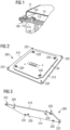
- FIG. 1 shows a thermal device 100 according to the invention for a light device of a motor vehicle.
- the light device further comprises a printed circuit 10 which supports a power supply control circuit for light sources, for example light-emitting diodes LED.
- the power supply control circuit generally involves a converter circuit and produces heat.
- the figure also shows a housing 12 which covers the printed circuit, and which makes a tight seal with the edge of the heat dissipation device.
- the printed circuit comprises an opening through which passes a crimping pin 120 fixed to a portion of the face 112 of the support 110 of the heat dissipation device, said surface portion being generally planar.
- the crimping pin is fixed to the support 110 by brazing. It is used to maintain the printed circuit in a predetermined position by the location of the pins and the corresponding openings of the printed circuit.
- the opposite face 114 of the support 110 can accommodate cooling fins 130 in order to increase the surface of the heat dissipation device which is in contact with the ambient air, thus facilitating the exchange of heat .
- the fins are advantageously fixed to the support 110 by brazing.
- a support 110 of a small thickness either less than 2.5 mm, less than 1.5 mm, or for example 1 mm.
- the height of the pins 120 on the side 112 is chosen independently of the thickness of the support or of the piece of aluminum sheet 110.
- the height of the pins 120 must be large enough for the pins to pass through the openings provided in the circuit printed and stand out to allow the fixing of the printed circuit by crimping the pins.
- the height of the pins 120 can for example be at least 2.5 mm relative to the face 112 of the support 110.
- the base thereof In order to be able to carry out the crimping, during which a significant mechanical stress is applied to the pin, the base thereof must be aligned with the plane of the support 110.
- FIG. 2 shows a preferred embodiment of the heat dissipation device 200 according to the invention.
- the face 212 which supports the printed circuit 20 is shown.
- Crimping pegs 220 have been attached to the generally planar support 210. These pegs are used to hold the printed circuit in a predetermined position, passing through openings in the printed circuit provided for this purpose, before being crimped.
- a second set of crimping pins 222 is provided to fix thereto a casing which can cover the printed circuit in a sealed manner.
- picture 3 shows the same embodiment as the figure 2 , however the opposite face 214 of device 200 is shown.
- the pegs 220, 222 in this embodiment pass through an opening in the support 210 and comprise a shoulder which rests on a face 214 of the support 210.
- This arrangement facilitates the alignment of the pegs with respect to the flat support 210. Pins having a shoulder at one end are inserted into the openings of the support 210 provided for this purpose until the shoulder comes into contact with the face 214. In this position the pins are oriented perpendicularly relative to the support and can be brazed to assemble the parts in question.
- the crimping of the pins can advantageously create electrical contact between the upper face of the printed circuit, which does not face the support 110, 210 of the device, and the heat dissipation device itself, which represents usually zero electric potential or ground.
- an electrical track of the circuit includes the edges of an opening in the printed circuit through which one of the crimping pins passes, this contact is used to connect the electrical track in question to ground potential.
Landscapes
- Engineering & Computer Science (AREA)
- General Engineering & Computer Science (AREA)
- Cooling Or The Like Of Semiconductors Or Solid State Devices (AREA)
- Cooling Or The Like Of Electrical Apparatus (AREA)
- Arrangement Of Elements, Cooling, Sealing, Or The Like Of Lighting Devices (AREA)
- Non-Portable Lighting Devices Or Systems Thereof (AREA)
Claims (7)
- Leuchtvorrichtung für ein Kraftfahrzeug, die Folgendes beinhaltet:- eine Leiterplatte (10), die eine Schaltung zur Ansteuerung der Versorgung von Lichtquellen trägt; und- eine Vorrichtung zur Wärmeableitung (100, 200), die Folgendes beinhaltet:• einen metallenen Träger (110, 210), der mindestens einen Trägerabschnitt mit einer im Wesentlichen ebenen Form beinhaltet; und• mindestens einen Crimpstift (120, 220), der auf einer ersten Seite (112, 212) des metallenen Trägers (110, 210) befestigt ist,dadurch gekennzeichnet, dass der Crimpstift (120, 220) durch Löten befestigt ist, um eine dichte Verbindung zwischen dem Crimpstift (120, 220) und dem metallenen Träger (110, 210) herzustellen;und dass die Leiterplatte (10, 20) mit Hilfe des Crimpstifts (120, 220) an dem metallenen Träger (110, 210) befestigt ist.
- Leuchtvorrichtung nach Anspruch 1, dadurch gekennzeichnet, dass der metallene Träger (110, 210) eine Dicke aufweist, die kleiner ist als die Höhe des Crimpstifts (120, 220), die in Bezug auf die erste Seite (112, 212) des metallenen Trägers (110, 210) gemessen wird.
- Leuchtvorrichtung nach einem der Ansprüche 1 oder 2, dadurch gekennzeichnet, dass der metallene Träger (110, 210) eine Dicke kleiner als 2,5 mm aufweist.
- Leuchtvorrichtung nach einem der Ansprüche 1 bis 3, dadurch gekennzeichnet, dass der metallene Träger (110, 210) aus Aluminium ist.
- Leuchtvorrichtung nach einem der Ansprüche 1 bis 4, dadurch gekennzeichnet, dass der metallene Träger (110, 210) und der Crimpstift (120, 220) aus identischen Materialien sind.
- Leuchtvorrichtung nach einem der Ansprüche 1 bis 5, dadurch gekennzeichnet, dass auf einer zweiten Seite (114) des metallenen Trägers (110, 210) Kühlrippen (130) durch Löten befestigt sind.
- Verfahren für die Montage der Leiterplatte (10, 20) auf der Vorrichtung zur Wärmeableitung (100, 200) der Leuchtvorrichtung für ein Kraftfahrzeug nach einem der Ansprüche 1 bis 6, dadurch gekennzeichnet, dass das Verfahren die folgenden Schritte beinhaltet:- Ausrichten mindestens einer Öffnung der Leiterplatte (10, 20) in Bezug auf mindestens einen Crimpstift (120, 220) der Vorrichtung zur Wärmeableitung (100, 200);- Aufsetzen der Leiterplatte (10, 20) auf den metallenen Träger (110, 210) der Vorrichtung zur Wärmeableitung (100, 200), sodass der Crimpstift (120, 220) durch die Öffnung hindurchgeht;- Crimpen (120, 220) des Stifts, um die Leiterplatte (10, 20) an der Vorrichtung zur Wärmeableitung (100, 200) zu befestigen, wobei der Schritt des Crimpens (120, 220) den Schritt des elektrischen In-Kontakt-Bringens mindestens einer elektrischen Leiterbahn der Leiterplatte (10, 20) mit dem Crimpstift (120, 220) beinhaltet, um die elektrische Leiterbahn mit dem elektrischen Massepotenzial zu verbinden.
Applications Claiming Priority (1)
| Application Number | Priority Date | Filing Date | Title |
|---|---|---|---|
| FR1651471A FR3048062B1 (fr) | 2016-02-23 | 2016-02-23 | Dispositif de dissipation thermique pour un dispositif lumineux d'un vehicule automobile |
Publications (2)
| Publication Number | Publication Date |
|---|---|
| EP3211293A1 EP3211293A1 (de) | 2017-08-30 |
| EP3211293B1 true EP3211293B1 (de) | 2023-04-05 |
Family
ID=55953251
Family Applications (1)
| Application Number | Title | Priority Date | Filing Date |
|---|---|---|---|
| EP17156709.2A Active EP3211293B1 (de) | 2016-02-23 | 2017-02-17 | Vorrichtung zur wärmeableitung für eine leuchtvorrichtung eines kraftfahrzeugs |
Country Status (4)
| Country | Link |
|---|---|
| US (1) | US20170241618A1 (de) |
| EP (1) | EP3211293B1 (de) |
| CN (1) | CN107101179B (de) |
| FR (1) | FR3048062B1 (de) |
Families Citing this family (4)
| Publication number | Priority date | Publication date | Assignee | Title |
|---|---|---|---|---|
| FR3074881B1 (fr) * | 2017-12-07 | 2025-08-01 | Valeo Vision | Module lumineux pour vehicule automobile |
| DE102018009292A1 (de) * | 2018-11-26 | 2020-05-28 | Harting Ag | Elektrooptische Baugruppe mit Wärmeabführung sowie Verfahren zur Herstellung einer solchen Baugruppe |
| FR3104678B1 (fr) | 2019-12-11 | 2021-12-10 | Valeo Vision | Dispositif lumineux d’un véhicule automobile |
| CN119713177A (zh) * | 2023-09-28 | 2025-03-28 | 市光法雷奥(佛山)汽车照明系统有限公司 | 出光模块、车灯组件和机动车辆 |
Family Cites Families (15)
| Publication number | Priority date | Publication date | Assignee | Title |
|---|---|---|---|---|
| US5676305A (en) * | 1996-04-18 | 1997-10-14 | Motorola, Inc. | Method to achieve regulated force contact in pin transfer deposition of liquidus substances |
| US6749105B2 (en) * | 2002-03-21 | 2004-06-15 | Motorola, Inc. | Method and apparatus for securing a metallic substrate to a metallic housing |
| JP2006128652A (ja) * | 2004-09-29 | 2006-05-18 | Furukawa Electric Co Ltd:The | 発光部品搭載フラットケーブルの固定構造 |
| DE102007002839A1 (de) * | 2006-09-08 | 2008-03-27 | Robert Bosch Gmbh | Leuchtaggregat mit mehreren LED-Bauelementen und Verfahren zu seiner Herstellung |
| CN201215138Y (zh) * | 2008-04-28 | 2009-04-01 | 江苏希西维轴承有限公司 | 无油自润滑轴承 |
| CN101530947B (zh) * | 2009-04-08 | 2012-07-04 | 西安交通大学 | 一种搅拌摩擦钎焊制备双金属复合板的方法 |
| CN101907909A (zh) * | 2009-06-05 | 2010-12-08 | 鸿富锦精密工业(深圳)有限公司 | 具有固定孔的主板 |
| JP5054148B2 (ja) * | 2010-04-14 | 2012-10-24 | 株式会社日本自動車部品総合研究所 | 車両用前照灯 |
| KR101823677B1 (ko) * | 2011-04-21 | 2018-01-30 | 엘지이노텍 주식회사 | 엘이디 조명장치 |
| WO2013180178A1 (ja) * | 2012-05-29 | 2013-12-05 | 市光工業株式会社 | 車両用灯具の半導体型光源の光源ユニット、車両用灯具 |
| DE102012218538A1 (de) * | 2012-10-11 | 2014-04-17 | Arnold & Richter Cine Technik Gmbh & Co. Betriebs Kg | Verfahren zur Herstellung einer Lichterzeugungseinheit |
| CN202905712U (zh) * | 2012-10-16 | 2013-04-24 | 孔明 | 一种具有金属隔板的焊接板 |
| US9153886B2 (en) * | 2012-10-26 | 2015-10-06 | Continental Automotive Systems, Inc. | Pin header assembly and method of forming the same |
| FR3004787B1 (fr) * | 2013-04-19 | 2017-09-08 | Valeo Vision | Organe de refroidissement et dispositif d'eclairage ou de signalisation de vehicule automobile comprenant un tel organe |
| FR3022867B1 (fr) * | 2014-06-30 | 2016-07-15 | Valeo Vision | Dispositif lumineux pour vehicule automobile a moyens d'assemblage perfectionnes |
-
2016
- 2016-02-23 FR FR1651471A patent/FR3048062B1/fr active Active
-
2017
- 2017-02-17 EP EP17156709.2A patent/EP3211293B1/de active Active
- 2017-02-21 CN CN201710093057.4A patent/CN107101179B/zh active Active
- 2017-02-23 US US15/440,174 patent/US20170241618A1/en not_active Abandoned
Also Published As
| Publication number | Publication date |
|---|---|
| CN107101179A (zh) | 2017-08-29 |
| CN107101179B (zh) | 2021-12-03 |
| US20170241618A1 (en) | 2017-08-24 |
| FR3048062B1 (fr) | 2018-03-09 |
| EP3211293A1 (de) | 2017-08-30 |
| FR3048062A1 (fr) | 2017-08-25 |
Similar Documents
| Publication | Publication Date | Title |
|---|---|---|
| EP2306599B1 (de) | Halterung für lichtquelle eines beleuchtungsmoduls | |
| EP3211293B1 (de) | Vorrichtung zur wärmeableitung für eine leuchtvorrichtung eines kraftfahrzeugs | |
| EP1981315B1 (de) | Ausgerüsteter flexibler elektronischer Träger, der mindestens eine Leuchtdiode umfasst, und entsprechendes Kraftfahrzeugscheinwerfer. | |
| EP3002511B1 (de) | Vorrichtung mit halbleiterkomponente, die auf einem wärmeableiter montiert ist, montageverfahren und eine solche vorrichtung umfassende beleuchtungsvorrichtung für kraftfahrzeug | |
| EP3073180A1 (de) | Led-halterung mit aufnahmefläche und elektrischem anschluss durch überbrückung | |
| EP1860707A1 (de) | Wärmeableitunseinrichtung und LED Beleuchtungs- und/oder Signalvorrichtung mit einer solchen Einrichtung | |
| FR3048153B1 (fr) | Module lumineux pour un vehicule automobile avec reprise de masse | |
| FR2994788A1 (fr) | Module d'eclairage comprenant un dispositif de commande maintenu de maniere amovible sur un support | |
| FR3041080A1 (fr) | Dispositif de dissipation thermique pour un module lumineux de vehicule automobile | |
| EP2730837A1 (de) | Beleuchtungsmodul mit verschiedenen Wärmesenken montiert auf einer gemeinsamen Platine | |
| FR3055401A1 (fr) | Module lumineux de vehicule automobile a organe de refroidissement | |
| FR3026226A1 (fr) | Plaque de circuit | |
| FR2862424A1 (fr) | Dispositif de refroidissement d'un composant electrique et procede de fabrication de ce dispositif | |
| FR3041211A1 (fr) | Dispositif de pilotage de l’alimentation electrique d’une source lumineuse pour un dispositif d’eclairage de vehicule automobile | |
| EP3270040B1 (de) | Leuchtmodul für kraftfahrzeug | |
| EP4062259A1 (de) | Bordcomputer mit interposer auf dem mikroprozessorchip | |
| EP3587907A1 (de) | Optisches modul, dass eine elektronische karte mit einem elektronischen chip umfasst | |
| WO2015044359A1 (fr) | Fixation d'une optique secondaire sur un récepteur photovoltaïque | |
| FR3065114A1 (fr) | Dispositif electrique et procede d'assemblage du dispositif electrique | |
| FR3137439A1 (fr) | Dispositif de signalisation de véhicule automobile | |
| WO2020053190A1 (fr) | Système lumineux pour véhicule | |
| FR3093397A1 (fr) | Boitier de module électronique avec organe de de dissipation thermique. | |
| FR2841729A3 (fr) | Agencement avec composants electriques | |
| FR2928489A1 (fr) | Matrice de microcontactage electrique , et module de commande electrique associe | |
| FR3041169A1 (fr) | Assemblage comprenant une pluralite de circuits imprimes interconnectes pour un module lumineux |
Legal Events
| Date | Code | Title | Description |
|---|---|---|---|
| PUAI | Public reference made under article 153(3) epc to a published international application that has entered the european phase |
Free format text: ORIGINAL CODE: 0009012 |
|
| STAA | Information on the status of an ep patent application or granted ep patent |
Free format text: STATUS: THE APPLICATION HAS BEEN PUBLISHED |
|
| AK | Designated contracting states |
Kind code of ref document: A1 Designated state(s): AL AT BE BG CH CY CZ DE DK EE ES FI FR GB GR HR HU IE IS IT LI LT LU LV MC MK MT NL NO PL PT RO RS SE SI SK SM TR |
|
| AX | Request for extension of the european patent |
Extension state: BA ME |
|
| STAA | Information on the status of an ep patent application or granted ep patent |
Free format text: STATUS: REQUEST FOR EXAMINATION WAS MADE |
|
| 17P | Request for examination filed |
Effective date: 20180221 |
|
| RBV | Designated contracting states (corrected) |
Designated state(s): AL AT BE BG CH CY CZ DE DK EE ES FI FR GB GR HR HU IE IS IT LI LT LU LV MC MK MT NL NO PL PT RO RS SE SI SK SM TR |
|
| STAA | Information on the status of an ep patent application or granted ep patent |
Free format text: STATUS: EXAMINATION IS IN PROGRESS |
|
| 17Q | First examination report despatched |
Effective date: 20210426 |
|
| REG | Reference to a national code |
Ref country code: DE Ref legal event code: R079 Ref document number: 602017067374 Country of ref document: DE Free format text: PREVIOUS MAIN CLASS: F21S0008100000 Ipc: F21S0045500000 |
|
| GRAP | Despatch of communication of intention to grant a patent |
Free format text: ORIGINAL CODE: EPIDOSNIGR1 |
|
| STAA | Information on the status of an ep patent application or granted ep patent |
Free format text: STATUS: GRANT OF PATENT IS INTENDED |
|
| RIC1 | Information provided on ipc code assigned before grant |
Ipc: F21S 45/49 20180101ALI20220920BHEP Ipc: F21S 45/47 20180101ALI20220920BHEP Ipc: F21S 41/19 20180101ALI20220920BHEP Ipc: F21S 45/50 20180101AFI20220920BHEP |
|
| INTG | Intention to grant announced |
Effective date: 20221021 |
|
| GRAS | Grant fee paid |
Free format text: ORIGINAL CODE: EPIDOSNIGR3 |
|
| GRAA | (expected) grant |
Free format text: ORIGINAL CODE: 0009210 |
|
| STAA | Information on the status of an ep patent application or granted ep patent |
Free format text: STATUS: THE PATENT HAS BEEN GRANTED |
|
| AK | Designated contracting states |
Kind code of ref document: B1 Designated state(s): AL AT BE BG CH CY CZ DE DK EE ES FI FR GB GR HR HU IE IS IT LI LT LU LV MC MK MT NL NO PL PT RO RS SE SI SK SM TR |
|
| REG | Reference to a national code |
Ref country code: GB Ref legal event code: FG4D Free format text: NOT ENGLISH |
|
| REG | Reference to a national code |
Ref country code: CH Ref legal event code: EP |
|
| REG | Reference to a national code |
Ref country code: AT Ref legal event code: REF Ref document number: 1558485 Country of ref document: AT Kind code of ref document: T Effective date: 20230415 |
|
| REG | Reference to a national code |
Ref country code: DE Ref legal event code: R096 Ref document number: 602017067374 Country of ref document: DE |
|
| REG | Reference to a national code |
Ref country code: IE Ref legal event code: FG4D Free format text: LANGUAGE OF EP DOCUMENT: FRENCH |
|
| P01 | Opt-out of the competence of the unified patent court (upc) registered |
Effective date: 20230528 |
|
| REG | Reference to a national code |
Ref country code: LT Ref legal event code: MG9D |
|
| REG | Reference to a national code |
Ref country code: NL Ref legal event code: MP Effective date: 20230405 |
|
| REG | Reference to a national code |
Ref country code: AT Ref legal event code: MK05 Ref document number: 1558485 Country of ref document: AT Kind code of ref document: T Effective date: 20230405 |
|
| PG25 | Lapsed in a contracting state [announced via postgrant information from national office to epo] |
Ref country code: NL Free format text: LAPSE BECAUSE OF FAILURE TO SUBMIT A TRANSLATION OF THE DESCRIPTION OR TO PAY THE FEE WITHIN THE PRESCRIBED TIME-LIMIT Effective date: 20230405 |
|
| PG25 | Lapsed in a contracting state [announced via postgrant information from national office to epo] |
Ref country code: SE Free format text: LAPSE BECAUSE OF FAILURE TO SUBMIT A TRANSLATION OF THE DESCRIPTION OR TO PAY THE FEE WITHIN THE PRESCRIBED TIME-LIMIT Effective date: 20230405 Ref country code: PT Free format text: LAPSE BECAUSE OF FAILURE TO SUBMIT A TRANSLATION OF THE DESCRIPTION OR TO PAY THE FEE WITHIN THE PRESCRIBED TIME-LIMIT Effective date: 20230807 Ref country code: NO Free format text: LAPSE BECAUSE OF FAILURE TO SUBMIT A TRANSLATION OF THE DESCRIPTION OR TO PAY THE FEE WITHIN THE PRESCRIBED TIME-LIMIT Effective date: 20230705 Ref country code: ES Free format text: LAPSE BECAUSE OF FAILURE TO SUBMIT A TRANSLATION OF THE DESCRIPTION OR TO PAY THE FEE WITHIN THE PRESCRIBED TIME-LIMIT Effective date: 20230405 Ref country code: AT Free format text: LAPSE BECAUSE OF FAILURE TO SUBMIT A TRANSLATION OF THE DESCRIPTION OR TO PAY THE FEE WITHIN THE PRESCRIBED TIME-LIMIT Effective date: 20230405 |
|
| PG25 | Lapsed in a contracting state [announced via postgrant information from national office to epo] |
Ref country code: RS Free format text: LAPSE BECAUSE OF FAILURE TO SUBMIT A TRANSLATION OF THE DESCRIPTION OR TO PAY THE FEE WITHIN THE PRESCRIBED TIME-LIMIT Effective date: 20230405 Ref country code: PL Free format text: LAPSE BECAUSE OF FAILURE TO SUBMIT A TRANSLATION OF THE DESCRIPTION OR TO PAY THE FEE WITHIN THE PRESCRIBED TIME-LIMIT Effective date: 20230405 Ref country code: LV Free format text: LAPSE BECAUSE OF FAILURE TO SUBMIT A TRANSLATION OF THE DESCRIPTION OR TO PAY THE FEE WITHIN THE PRESCRIBED TIME-LIMIT Effective date: 20230405 Ref country code: LT Free format text: LAPSE BECAUSE OF FAILURE TO SUBMIT A TRANSLATION OF THE DESCRIPTION OR TO PAY THE FEE WITHIN THE PRESCRIBED TIME-LIMIT Effective date: 20230405 Ref country code: IS Free format text: LAPSE BECAUSE OF FAILURE TO SUBMIT A TRANSLATION OF THE DESCRIPTION OR TO PAY THE FEE WITHIN THE PRESCRIBED TIME-LIMIT Effective date: 20230805 Ref country code: HR Free format text: LAPSE BECAUSE OF FAILURE TO SUBMIT A TRANSLATION OF THE DESCRIPTION OR TO PAY THE FEE WITHIN THE PRESCRIBED TIME-LIMIT Effective date: 20230405 Ref country code: GR Free format text: LAPSE BECAUSE OF FAILURE TO SUBMIT A TRANSLATION OF THE DESCRIPTION OR TO PAY THE FEE WITHIN THE PRESCRIBED TIME-LIMIT Effective date: 20230706 Ref country code: AL Free format text: LAPSE BECAUSE OF FAILURE TO SUBMIT A TRANSLATION OF THE DESCRIPTION OR TO PAY THE FEE WITHIN THE PRESCRIBED TIME-LIMIT Effective date: 20230405 |
|
| PG25 | Lapsed in a contracting state [announced via postgrant information from national office to epo] |
Ref country code: FI Free format text: LAPSE BECAUSE OF FAILURE TO SUBMIT A TRANSLATION OF THE DESCRIPTION OR TO PAY THE FEE WITHIN THE PRESCRIBED TIME-LIMIT Effective date: 20230405 |
|
| REG | Reference to a national code |
Ref country code: DE Ref legal event code: R097 Ref document number: 602017067374 Country of ref document: DE |
|
| PG25 | Lapsed in a contracting state [announced via postgrant information from national office to epo] |
Ref country code: SK Free format text: LAPSE BECAUSE OF FAILURE TO SUBMIT A TRANSLATION OF THE DESCRIPTION OR TO PAY THE FEE WITHIN THE PRESCRIBED TIME-LIMIT Effective date: 20230405 |
|
| PG25 | Lapsed in a contracting state [announced via postgrant information from national office to epo] |
Ref country code: SM Free format text: LAPSE BECAUSE OF FAILURE TO SUBMIT A TRANSLATION OF THE DESCRIPTION OR TO PAY THE FEE WITHIN THE PRESCRIBED TIME-LIMIT Effective date: 20230405 Ref country code: SK Free format text: LAPSE BECAUSE OF FAILURE TO SUBMIT A TRANSLATION OF THE DESCRIPTION OR TO PAY THE FEE WITHIN THE PRESCRIBED TIME-LIMIT Effective date: 20230405 Ref country code: RO Free format text: LAPSE BECAUSE OF FAILURE TO SUBMIT A TRANSLATION OF THE DESCRIPTION OR TO PAY THE FEE WITHIN THE PRESCRIBED TIME-LIMIT Effective date: 20230405 Ref country code: EE Free format text: LAPSE BECAUSE OF FAILURE TO SUBMIT A TRANSLATION OF THE DESCRIPTION OR TO PAY THE FEE WITHIN THE PRESCRIBED TIME-LIMIT Effective date: 20230405 Ref country code: DK Free format text: LAPSE BECAUSE OF FAILURE TO SUBMIT A TRANSLATION OF THE DESCRIPTION OR TO PAY THE FEE WITHIN THE PRESCRIBED TIME-LIMIT Effective date: 20230405 Ref country code: CZ Free format text: LAPSE BECAUSE OF FAILURE TO SUBMIT A TRANSLATION OF THE DESCRIPTION OR TO PAY THE FEE WITHIN THE PRESCRIBED TIME-LIMIT Effective date: 20230405 |
|
| PLBE | No opposition filed within time limit |
Free format text: ORIGINAL CODE: 0009261 |
|
| STAA | Information on the status of an ep patent application or granted ep patent |
Free format text: STATUS: NO OPPOSITION FILED WITHIN TIME LIMIT |
|
| 26N | No opposition filed |
Effective date: 20240108 |
|
| PG25 | Lapsed in a contracting state [announced via postgrant information from national office to epo] |
Ref country code: SI Free format text: LAPSE BECAUSE OF FAILURE TO SUBMIT A TRANSLATION OF THE DESCRIPTION OR TO PAY THE FEE WITHIN THE PRESCRIBED TIME-LIMIT Effective date: 20230405 |
|
| PG25 | Lapsed in a contracting state [announced via postgrant information from national office to epo] |
Ref country code: SI Free format text: LAPSE BECAUSE OF FAILURE TO SUBMIT A TRANSLATION OF THE DESCRIPTION OR TO PAY THE FEE WITHIN THE PRESCRIBED TIME-LIMIT Effective date: 20230405 Ref country code: IT Free format text: LAPSE BECAUSE OF FAILURE TO SUBMIT A TRANSLATION OF THE DESCRIPTION OR TO PAY THE FEE WITHIN THE PRESCRIBED TIME-LIMIT Effective date: 20230405 |
|
| PG25 | Lapsed in a contracting state [announced via postgrant information from national office to epo] |
Ref country code: MC Free format text: LAPSE BECAUSE OF FAILURE TO SUBMIT A TRANSLATION OF THE DESCRIPTION OR TO PAY THE FEE WITHIN THE PRESCRIBED TIME-LIMIT Effective date: 20230405 |
|
| REG | Reference to a national code |
Ref country code: CH Ref legal event code: PL |
|
| PG25 | Lapsed in a contracting state [announced via postgrant information from national office to epo] |
Ref country code: LU Free format text: LAPSE BECAUSE OF NON-PAYMENT OF DUE FEES Effective date: 20240217 |
|
| PG25 | Lapsed in a contracting state [announced via postgrant information from national office to epo] |
Ref country code: CH Free format text: LAPSE BECAUSE OF NON-PAYMENT OF DUE FEES Effective date: 20240229 |
|
| GBPC | Gb: european patent ceased through non-payment of renewal fee |
Effective date: 20240217 |
|
| PG25 | Lapsed in a contracting state [announced via postgrant information from national office to epo] |
Ref country code: LU Free format text: LAPSE BECAUSE OF NON-PAYMENT OF DUE FEES Effective date: 20240217 Ref country code: CH Free format text: LAPSE BECAUSE OF NON-PAYMENT OF DUE FEES Effective date: 20240229 |
|
| PG25 | Lapsed in a contracting state [announced via postgrant information from national office to epo] |
Ref country code: BG Free format text: LAPSE BECAUSE OF FAILURE TO SUBMIT A TRANSLATION OF THE DESCRIPTION OR TO PAY THE FEE WITHIN THE PRESCRIBED TIME-LIMIT Effective date: 20230405 |
|
| PG25 | Lapsed in a contracting state [announced via postgrant information from national office to epo] |
Ref country code: BG Free format text: LAPSE BECAUSE OF FAILURE TO SUBMIT A TRANSLATION OF THE DESCRIPTION OR TO PAY THE FEE WITHIN THE PRESCRIBED TIME-LIMIT Effective date: 20230405 |
|
| REG | Reference to a national code |
Ref country code: BE Ref legal event code: MM Effective date: 20240229 |
|
| PG25 | Lapsed in a contracting state [announced via postgrant information from national office to epo] |
Ref country code: BE Free format text: LAPSE BECAUSE OF NON-PAYMENT OF DUE FEES Effective date: 20240229 |
|
| PG25 | Lapsed in a contracting state [announced via postgrant information from national office to epo] |
Ref country code: GB Free format text: LAPSE BECAUSE OF NON-PAYMENT OF DUE FEES Effective date: 20240217 |
|
| PG25 | Lapsed in a contracting state [announced via postgrant information from national office to epo] |
Ref country code: IE Free format text: LAPSE BECAUSE OF NON-PAYMENT OF DUE FEES Effective date: 20240217 |
|
| PG25 | Lapsed in a contracting state [announced via postgrant information from national office to epo] |
Ref country code: IE Free format text: LAPSE BECAUSE OF NON-PAYMENT OF DUE FEES Effective date: 20240217 Ref country code: GB Free format text: LAPSE BECAUSE OF NON-PAYMENT OF DUE FEES Effective date: 20240217 Ref country code: BE Free format text: LAPSE BECAUSE OF NON-PAYMENT OF DUE FEES Effective date: 20240229 |
|
| PG25 | Lapsed in a contracting state [announced via postgrant information from national office to epo] |
Ref country code: CY Free format text: LAPSE BECAUSE OF FAILURE TO SUBMIT A TRANSLATION OF THE DESCRIPTION OR TO PAY THE FEE WITHIN THE PRESCRIBED TIME-LIMIT; INVALID AB INITIO Effective date: 20170217 |
|
| PG25 | Lapsed in a contracting state [announced via postgrant information from national office to epo] |
Ref country code: HU Free format text: LAPSE BECAUSE OF FAILURE TO SUBMIT A TRANSLATION OF THE DESCRIPTION OR TO PAY THE FEE WITHIN THE PRESCRIBED TIME-LIMIT; INVALID AB INITIO Effective date: 20170217 |
|
| PG25 | Lapsed in a contracting state [announced via postgrant information from national office to epo] |
Ref country code: TR Free format text: LAPSE BECAUSE OF FAILURE TO SUBMIT A TRANSLATION OF THE DESCRIPTION OR TO PAY THE FEE WITHIN THE PRESCRIBED TIME-LIMIT Effective date: 20230405 |
|
| PGFP | Annual fee paid to national office [announced via postgrant information from national office to epo] |
Ref country code: DE Payment date: 20260206 Year of fee payment: 10 |
|
| PGFP | Annual fee paid to national office [announced via postgrant information from national office to epo] |
Ref country code: FR Payment date: 20260227 Year of fee payment: 10 |