EP3213863A1 - Procédé de fusion électrique pour la formation d'une structure métallique - Google Patents
Procédé de fusion électrique pour la formation d'une structure métallique Download PDFInfo
- Publication number
- EP3213863A1 EP3213863A1 EP15856920.2A EP15856920A EP3213863A1 EP 3213863 A1 EP3213863 A1 EP 3213863A1 EP 15856920 A EP15856920 A EP 15856920A EP 3213863 A1 EP3213863 A1 EP 3213863A1
- Authority
- EP
- European Patent Office
- Prior art keywords
- electric melting
- base material
- electric
- metal
- layer
- Prior art date
- Legal status (The legal status is an assumption and is not a legal conclusion. Google has not performed a legal analysis and makes no representation as to the accuracy of the status listed.)
- Withdrawn
Links
Images
Classifications
-
- B—PERFORMING OPERATIONS; TRANSPORTING
- B23—MACHINE TOOLS; METAL-WORKING NOT OTHERWISE PROVIDED FOR
- B23K—SOLDERING OR UNSOLDERING; WELDING; CLADDING OR PLATING BY SOLDERING OR WELDING; CUTTING BY APPLYING HEAT LOCALLY, e.g. FLAME CUTTING; WORKING BY LASER BEAM
- B23K28/00—Welding or cutting not covered by groups B23K5/00 - B23K26/00
- B23K28/02—Combined welding or cutting procedures or apparatus
-
- B—PERFORMING OPERATIONS; TRANSPORTING
- B23—MACHINE TOOLS; METAL-WORKING NOT OTHERWISE PROVIDED FOR
- B23K—SOLDERING OR UNSOLDERING; WELDING; CLADDING OR PLATING BY SOLDERING OR WELDING; CUTTING BY APPLYING HEAT LOCALLY, e.g. FLAME CUTTING; WORKING BY LASER BEAM
- B23K9/00—Arc welding or cutting
- B23K9/04—Welding for other purposes than joining, e.g. built-up welding
-
- B—PERFORMING OPERATIONS; TRANSPORTING
- B05—SPRAYING OR ATOMISING IN GENERAL; APPLYING FLUENT MATERIALS TO SURFACES, IN GENERAL
- B05C—APPARATUS FOR APPLYING FLUENT MATERIALS TO SURFACES, IN GENERAL
- B05C19/00—Apparatus specially adapted for applying particulate materials to surfaces
- B05C19/04—Apparatus specially adapted for applying particulate materials to surfaces the particulate material being projected, poured or allowed to flow onto the surface of the work
-
- B—PERFORMING OPERATIONS; TRANSPORTING
- B22—CASTING; POWDER METALLURGY
- B22F—WORKING METALLIC POWDER; MANUFACTURE OF ARTICLES FROM METALLIC POWDER; MAKING METALLIC POWDER; APPARATUS OR DEVICES SPECIALLY ADAPTED FOR METALLIC POWDER
- B22F10/00—Additive manufacturing of workpieces or articles from metallic powder
- B22F10/20—Direct sintering or melting
- B22F10/25—Direct deposition of metal particles, e.g. direct metal deposition [DMD] or laser engineered net shaping [LENS]
-
- B—PERFORMING OPERATIONS; TRANSPORTING
- B22—CASTING; POWDER METALLURGY
- B22F—WORKING METALLIC POWDER; MANUFACTURE OF ARTICLES FROM METALLIC POWDER; MAKING METALLIC POWDER; APPARATUS OR DEVICES SPECIALLY ADAPTED FOR METALLIC POWDER
- B22F12/00—Apparatus or devices specially adapted for additive manufacturing; Auxiliary means for additive manufacturing; Combinations of additive manufacturing apparatus or devices with other processing apparatus or devices
- B22F12/30—Platforms or substrates
- B22F12/37—Rotatable
-
- B—PERFORMING OPERATIONS; TRANSPORTING
- B22—CASTING; POWDER METALLURGY
- B22F—WORKING METALLIC POWDER; MANUFACTURE OF ARTICLES FROM METALLIC POWDER; MAKING METALLIC POWDER; APPARATUS OR DEVICES SPECIALLY ADAPTED FOR METALLIC POWDER
- B22F12/00—Apparatus or devices specially adapted for additive manufacturing; Auxiliary means for additive manufacturing; Combinations of additive manufacturing apparatus or devices with other processing apparatus or devices
- B22F12/50—Means for feeding of material, e.g. heads
- B22F12/55—Two or more means for feeding material
-
- B—PERFORMING OPERATIONS; TRANSPORTING
- B23—MACHINE TOOLS; METAL-WORKING NOT OTHERWISE PROVIDED FOR
- B23K—SOLDERING OR UNSOLDERING; WELDING; CLADDING OR PLATING BY SOLDERING OR WELDING; CUTTING BY APPLYING HEAT LOCALLY, e.g. FLAME CUTTING; WORKING BY LASER BEAM
- B23K25/00—Slag welding, i.e. using a heated layer or mass of powder, slag or the like in contact with the material to be joined
- B23K25/005—Welding for purposes other than joining, e.g. build-up welding
-
- B—PERFORMING OPERATIONS; TRANSPORTING
- B23—MACHINE TOOLS; METAL-WORKING NOT OTHERWISE PROVIDED FOR
- B23K—SOLDERING OR UNSOLDERING; WELDING; CLADDING OR PLATING BY SOLDERING OR WELDING; CUTTING BY APPLYING HEAT LOCALLY, e.g. FLAME CUTTING; WORKING BY LASER BEAM
- B23K9/00—Arc welding or cutting
- B23K9/18—Submerged-arc welding
-
- B—PERFORMING OPERATIONS; TRANSPORTING
- B28—WORKING CEMENT, CLAY, OR STONE
- B28B—SHAPING CLAY OR OTHER CERAMIC COMPOSITIONS; SHAPING SLAG; SHAPING MIXTURES CONTAINING CEMENTITIOUS MATERIAL, e.g. PLASTER
- B28B1/00—Producing shaped prefabricated articles from the material
- B28B1/001—Rapid manufacturing of 3D objects by additive depositing, agglomerating or laminating of material
-
- B—PERFORMING OPERATIONS; TRANSPORTING
- B29—WORKING OF PLASTICS; WORKING OF SUBSTANCES IN A PLASTIC STATE IN GENERAL
- B29C—SHAPING OR JOINING OF PLASTICS; SHAPING OF MATERIAL IN A PLASTIC STATE, NOT OTHERWISE PROVIDED FOR; AFTER-TREATMENT OF THE SHAPED PRODUCTS, e.g. REPAIRING
- B29C64/00—Additive manufacturing, i.e. manufacturing of three-dimensional [3D] objects by additive deposition, additive agglomeration or additive layering, e.g. by 3D printing, stereolithography or selective laser sintering
- B29C64/10—Processes of additive manufacturing
- B29C64/141—Processes of additive manufacturing using only solid materials
- B29C64/153—Processes of additive manufacturing using only solid materials using layers of powder being selectively joined, e.g. by selective laser sintering or melting
-
- B—PERFORMING OPERATIONS; TRANSPORTING
- B29—WORKING OF PLASTICS; WORKING OF SUBSTANCES IN A PLASTIC STATE IN GENERAL
- B29C—SHAPING OR JOINING OF PLASTICS; SHAPING OF MATERIAL IN A PLASTIC STATE, NOT OTHERWISE PROVIDED FOR; AFTER-TREATMENT OF THE SHAPED PRODUCTS, e.g. REPAIRING
- B29C64/00—Additive manufacturing, i.e. manufacturing of three-dimensional [3D] objects by additive deposition, additive agglomeration or additive layering, e.g. by 3D printing, stereolithography or selective laser sintering
- B29C64/20—Apparatus for additive manufacturing; Details thereof or accessories therefor
- B29C64/264—Arrangements for irradiation
- B29C64/277—Arrangements for irradiation using multiple radiation means, e.g. micromirrors or multiple light-emitting diodes [LED]
- B29C64/282—Arrangements for irradiation using multiple radiation means, e.g. micromirrors or multiple light-emitting diodes [LED] of the same type, e.g. using different energy levels
-
- B—PERFORMING OPERATIONS; TRANSPORTING
- B29—WORKING OF PLASTICS; WORKING OF SUBSTANCES IN A PLASTIC STATE IN GENERAL
- B29C—SHAPING OR JOINING OF PLASTICS; SHAPING OF MATERIAL IN A PLASTIC STATE, NOT OTHERWISE PROVIDED FOR; AFTER-TREATMENT OF THE SHAPED PRODUCTS, e.g. REPAIRING
- B29C64/00—Additive manufacturing, i.e. manufacturing of three-dimensional [3D] objects by additive deposition, additive agglomeration or additive layering, e.g. by 3D printing, stereolithography or selective laser sintering
- B29C64/20—Apparatus for additive manufacturing; Details thereof or accessories therefor
- B29C64/295—Heating elements
-
- B—PERFORMING OPERATIONS; TRANSPORTING
- B29—WORKING OF PLASTICS; WORKING OF SUBSTANCES IN A PLASTIC STATE IN GENERAL
- B29C—SHAPING OR JOINING OF PLASTICS; SHAPING OF MATERIAL IN A PLASTIC STATE, NOT OTHERWISE PROVIDED FOR; AFTER-TREATMENT OF THE SHAPED PRODUCTS, e.g. REPAIRING
- B29C70/00—Shaping composites, i.e. plastics material comprising reinforcements, fillers or preformed parts, e.g. inserts
- B29C70/68—Shaping composites, i.e. plastics material comprising reinforcements, fillers or preformed parts, e.g. inserts by incorporating or moulding on preformed parts, e.g. inserts or layers, e.g. foam blocks
- B29C70/82—Forcing wires, nets or the like partially or completely into the surface of an article, e.g. by cutting and pressing
-
- H—ELECTRICITY
- H05—ELECTRIC TECHNIQUES NOT OTHERWISE PROVIDED FOR
- H05K—PRINTED CIRCUITS; CASINGS OR CONSTRUCTIONAL DETAILS OF ELECTRIC APPARATUS; MANUFACTURE OF ASSEMBLAGES OF ELECTRICAL COMPONENTS
- H05K3/00—Apparatus or processes for manufacturing printed circuits
- H05K3/10—Apparatus or processes for manufacturing printed circuits in which conductive material is applied to the insulating support in such a manner as to form the desired conductive pattern
- H05K3/103—Apparatus or processes for manufacturing printed circuits in which conductive material is applied to the insulating support in such a manner as to form the desired conductive pattern by bonding or embedding conductive wires or strips
-
- B—PERFORMING OPERATIONS; TRANSPORTING
- B22—CASTING; POWDER METALLURGY
- B22F—WORKING METALLIC POWDER; MANUFACTURE OF ARTICLES FROM METALLIC POWDER; MAKING METALLIC POWDER; APPARATUS OR DEVICES SPECIALLY ADAPTED FOR METALLIC POWDER
- B22F10/00—Additive manufacturing of workpieces or articles from metallic powder
- B22F10/60—Treatment of workpieces or articles after build-up
- B22F10/66—Treatment of workpieces or articles after build-up by mechanical means
-
- B—PERFORMING OPERATIONS; TRANSPORTING
- B22—CASTING; POWDER METALLURGY
- B22F—WORKING METALLIC POWDER; MANUFACTURE OF ARTICLES FROM METALLIC POWDER; MAKING METALLIC POWDER; APPARATUS OR DEVICES SPECIALLY ADAPTED FOR METALLIC POWDER
- B22F10/00—Additive manufacturing of workpieces or articles from metallic powder
- B22F10/70—Recycling
- B22F10/73—Recycling of powder
-
- B—PERFORMING OPERATIONS; TRANSPORTING
- B22—CASTING; POWDER METALLURGY
- B22F—WORKING METALLIC POWDER; MANUFACTURE OF ARTICLES FROM METALLIC POWDER; MAKING METALLIC POWDER; APPARATUS OR DEVICES SPECIALLY ADAPTED FOR METALLIC POWDER
- B22F12/00—Apparatus or devices specially adapted for additive manufacturing; Auxiliary means for additive manufacturing; Combinations of additive manufacturing apparatus or devices with other processing apparatus or devices
- B22F12/10—Auxiliary heating means
-
- B—PERFORMING OPERATIONS; TRANSPORTING
- B22—CASTING; POWDER METALLURGY
- B22F—WORKING METALLIC POWDER; MANUFACTURE OF ARTICLES FROM METALLIC POWDER; MAKING METALLIC POWDER; APPARATUS OR DEVICES SPECIALLY ADAPTED FOR METALLIC POWDER
- B22F12/00—Apparatus or devices specially adapted for additive manufacturing; Auxiliary means for additive manufacturing; Combinations of additive manufacturing apparatus or devices with other processing apparatus or devices
- B22F12/20—Cooling means
-
- B—PERFORMING OPERATIONS; TRANSPORTING
- B22—CASTING; POWDER METALLURGY
- B22F—WORKING METALLIC POWDER; MANUFACTURE OF ARTICLES FROM METALLIC POWDER; MAKING METALLIC POWDER; APPARATUS OR DEVICES SPECIALLY ADAPTED FOR METALLIC POWDER
- B22F2202/00—Treatment under specific physical conditions
- B22F2202/06—Use of electric fields
-
- B—PERFORMING OPERATIONS; TRANSPORTING
- B22—CASTING; POWDER METALLURGY
- B22F—WORKING METALLIC POWDER; MANUFACTURE OF ARTICLES FROM METALLIC POWDER; MAKING METALLIC POWDER; APPARATUS OR DEVICES SPECIALLY ADAPTED FOR METALLIC POWDER
- B22F2999/00—Aspects linked to processes or compositions used in powder metallurgy
-
- B—PERFORMING OPERATIONS; TRANSPORTING
- B33—ADDITIVE MANUFACTURING TECHNOLOGY
- B33Y—ADDITIVE MANUFACTURING, i.e. MANUFACTURING OF THREE-DIMENSIONAL [3D] OBJECTS BY ADDITIVE DEPOSITION, ADDITIVE AGGLOMERATION OR ADDITIVE LAYERING, e.g. BY 3D PRINTING, STEREOLITHOGRAPHY OR SELECTIVE LASER SINTERING
- B33Y10/00—Processes of additive manufacturing
-
- B—PERFORMING OPERATIONS; TRANSPORTING
- B33—ADDITIVE MANUFACTURING TECHNOLOGY
- B33Y—ADDITIVE MANUFACTURING, i.e. MANUFACTURING OF THREE-DIMENSIONAL [3D] OBJECTS BY ADDITIVE DEPOSITION, ADDITIVE AGGLOMERATION OR ADDITIVE LAYERING, e.g. BY 3D PRINTING, STEREOLITHOGRAPHY OR SELECTIVE LASER SINTERING
- B33Y30/00—Apparatus for additive manufacturing; Details thereof or accessories therefor
-
- Y—GENERAL TAGGING OF NEW TECHNOLOGICAL DEVELOPMENTS; GENERAL TAGGING OF CROSS-SECTIONAL TECHNOLOGIES SPANNING OVER SEVERAL SECTIONS OF THE IPC; TECHNICAL SUBJECTS COVERED BY FORMER USPC CROSS-REFERENCE ART COLLECTIONS [XRACs] AND DIGESTS
- Y02—TECHNOLOGIES OR APPLICATIONS FOR MITIGATION OR ADAPTATION AGAINST CLIMATE CHANGE
- Y02P—CLIMATE CHANGE MITIGATION TECHNOLOGIES IN THE PRODUCTION OR PROCESSING OF GOODS
- Y02P10/00—Technologies related to metal processing
- Y02P10/25—Process efficiency
Definitions
- the present invention relates to electric melting methods for forming metal components.
- the formed component may cost a lot due to the fact of complex manufacturing process steps, long production cycle, low material utilization ratio.
- complex process and great difficulty in controlling the chemical and mechanical performance also cause poor stability of quality and high defective index.
- the special high-performance large-scale metal component still needs importing from Japanese companies like the Japan Steel Works and the Doosan Heavy Industries, etc., which hold a high price and has a strict export restrictions, thereby seriously impacting the progress of project constructions and limiting the development of China's heavy equipment manufacturing.
- 3D printing is widely applied in modeling/prototyping of molds of product module, for instance, low-melting point materials such as wax, resin and etc. are used to form/model the mold of a workpiece.
- 3D printing has achieved great breakthrough and application in the manufacturing of titanium alloy metal component in specific industries like aerospace, yet there are still many difficulties to be overcome if the 3D printing is going to totally enter the manufacturing industry, especially the heavy equipment manufacturing industry.
- the difficulties include the selection of high-energy density heat source which could melt high-melting point metal element and the design and manufacturing of a completely new 3D system; the R&D and preparing of raw material (e.g. wire or powder);.
- the main object of the present invention is to provide an electric melting method for forming metal components with high efficiency, low cost, and great mechanical properties.
- the electric melting method adopts a high-energy heat source composed of electric arc heat, resistance heat, and electroslag heat to melt raw metal wire fed continually, and create a metal component by solidifying and depositing the molten raw metal wire on a base material layer by layer; an electric melting head and a base material are connected to the anode and cathode of a power supply respectively; during the forming/modeling of the metal component, the raw metal wire is sent to a surface of the base material by a feeder and the electric melting head to electric arc is generate electric arc between the raw wire and the base material under the protection of the deposition of granular auxiliary material; wherein the electric arc melts a part of the deposited auxiliary material and creates a molten slag pool; an electric current flowing through the raw wire and the molten slag pool of auxiliary material generates resistance heat and electroslag heat; the raw wire is molten under the high-energy heat resource composed of the electric arc heat, resistance
- the raw wire and the auxiliary material are fed continuously and a computer is employed to control the relative movement of the electric melting head and the base material based on a laminated slicing data, such that the molten pool is rapidly cooled, solidified and deposited on the base material, and therefore the metal component with desired shape and size are formed after the layer-to-layer deposition.
- the electric current of the power supply may be 200A-6000A, the voltage of the power supply may be 20V-60V.
- the power supply may be a DC power supply or a AC power supply. When the DC power supply is employed, the electric melting head is connected to either the anode or the cathode of the power supply.
- the diameter of the raw wire may be ranged of 2 mm - 20 mm.
- the length extending out the electric melting (energization length) is ranged of 20 mm - 150 mm.
- the overlaying thickness of the auxiliary material in the forming process is ranged of 15 mm - 120 mm.
- the auxiliary material includes oxide, or a combination oxide and halide, or a combination of oxide, halide and metal powder. According to the requirement of forming efficiency and metallic composition of the component, no more than 30% of alloy powder and/or metallic simple substance powder may be added into the auxiliary material.
- the grannular auxiliary material reacts with the elements of the molten pool in the forming process, adjusting the alloy elements in the molten pool, improving the mechanical performance of the formed workpiece, and reducing the production cost.
- the surface temperature of the base material or the deposited metal layer is ranged of 100 - 600°C, and the speed of relative movement between the electric melting head and the base material is ranged of 150 - 3000 mm/min, thereby facilitating the rapid solidification of the molten pool, and obtaining a material with fine grain size, non-macrosegregation and homogeneous structure, such that mechanical properties, for example, plasticity, toughness, and high-temperature creep, of the formed workpiece is greatly improved.
- the high-temperature molten pool performs heat treatment on the deposited metal layer of the heat-affected zone of the lower layer, and the workpiece is treated by self-tempering layer after layer, such that the obtained grain size is finer and its structure is more stable.
- a molten pool is formed on a surface of metal of a lower layer by the raw wire, in which the molten droplet enters the molten pool in the form of jet and solidifies therein, rendering the two metal layers to form together as an integral.
- the layer-forming and integral fusion method ensures the overall performance of the formed metal component.
- a single electric melting head has a melting efficiency ranged of 10 - 80 Kg/h for the raw wire.
- the height of the metal layers deposited due to the relative movement of the electric melting head and base material is ranged of 1 - 8mm.
- the number of the electric melting head may be varied from 1 to 100 as desired.
- the interval of the adjacent electric melting heads may be ranged of 50 - 500 mm.
- the edge of the formed metal component may be supported and protected by the auxiliary material or metal substrate, preventing the molten metal from overflow.
- the dimension and shape of the base material are matched with the shape of the initially-deposited metal layer, and the thickness thereof no less than 5 mm is preferred.
- the base material and deposited metal may be of same or different material.
- the base material may be removed in the following machining process if the base material and the deposited metal are employing different material, whereas the base material may be kept as a part of the formed metal component if the base material is employing the same material as the deposited metal.
- the present invention gets rid of the restrictions of complex works, molds and specialized tools.
- the formed component is a near net shape preform which needs few finishing process after production, leading to great simplification of the manufacturing procedures and reduction of the production cycle.
- the formed workpiece has mechanical and chemical performance better, at least not worse, than that made by the traditional forging process.
- the performance of the formed component including strength, toughness, corrosion resistance and the like are very excellent.
- the method provided by the present invention can be applied to the forming and producing of various heavy metal components for all industries, for example, low-alloy steel, heat-resistant steel, stainless steel, and nickel-based alloy material.
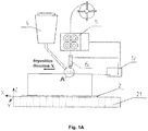
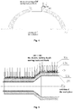
- Fig. 1A is a schematic diagram illustrating an electric melting method for forming a metal component according to one embodiment of the present invention.
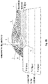
- Fig. 1B is a partial enlarging diagram of a neighboring region of point A in Fig. 1A .
- the actual shape and dimension etc. should not be limited by the illustration of the drawings.
- the raw wire 1 is molten and deposited on the base material 2 layer by layer ( Fig. 1 shows the state where N layers N has deposited), such that the desired metal component may be formed.
- a control device controls the way of the relative movement of the electric melting head 6 and base material 2 based on the laminated slicing data of the formed component o (numerical simulation, mathematical model).
- the electric melting head is connected to the anode of the power supply while the workpiece is connected to the cathode. It is to be noted that such connection is only exemplary. In other embodiments, the electric melting head may be connected to the cathode of the power supply whereas the workpiece is connected to the anode. In some embodiments, AC power supply may be employed.
- the parameters such as the composition of the auxiliary material, the diameter of the raw wire, the electric current, the speed of relative movement of the base material and the raw wire may be adjusted appropriately.
- the raw wire 1 may be shaped as round bar, belt, solid cored or flux cored.
- the diameter of the raw wire 1 may be ranged of 2 - 20 mm according to the dimension of the formed workpiece. Based on the various diameter of wire material 1, the length extending out the electric melting head (energization length) may be ranged of 20 mm - 150 mm.
- the overlaying thickness of the auxiliary material 3 is ranged of 15 mm - 120 mm.
- the use of auxiliary material 3 has the following advantages including: avoiding the splash of the electric arc 9 by covering the electric arc 9; protecting the metal of the molten pool from oxygen, nitrogen, hydrogen in the air by covering molten pool 11 and insulating the air; keeping the metal of the molten pool from losing temperature; removing impurities and doping alloys during the metallurgical reaction process; ensuring the excellent forming of the deposited metal 10 mechanically by the formed slag pool 8 (slag crust 7).
- the composition of the auxiliary material 3 includes oxide or a combination of oxide and halide.
- the auxiliary material 3 is involved in the reaction of molten pool to adjust the composition of the workpiece (metal component, product), therefore the alloy powder and/or the metal simple substance powder may be added into the auxiliary material based on the composition requirement and efficiency requirement of the metal component to be formed, thereby reducing the production cost.
- step C may comprise a further step of recycling the residual auxiliary material and removing the slag crust 7 which is formed by the solidification of the slag pool 8.
- the removing operation may be carried out mechanically or manually from a position behind the wire with a distance of 400 mm - 500 mm.
- the implementation of the electric melting forming method in the embodiments makes the utilization ratio of the raw wire approach 100%.
- the present method has less manufacturing process (complex heat treatment is not more needed), shorter production cycle, higher efficiency.
- the formed metal component has very small machining allowance reducing the time on finish machining and saving lots of material.
- the present embodiment illustrates a manufacturing process of cylinder by a horizontal electric melting forming method, in which the material adopted is common low-carbon steel, and the equipment used includes:
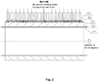
- Fig. 2 is a schematic diagram illustrating the forming method of the present embodiment, in which the power supply, the automatic wire feeder and etc. are omitted for simplicity.
- the electric melting heads are connected to the cathode of the power supply and the substrate is connected to the anode of the power supply (in the situation where DC power supply is employed, the manufacturing efficiency may be greatly improved with the electric melting heads being connected to the cathode of the power supply and the substrate being connected to the anode).
- the processing parameters of the electric melting are as follows: the electric melting current is of 700A, the electric melting voltage is of 35V, the speed of the relative movement of the electric melting head 401 and the base material 201 is of 500-600mm/min.
- the electric melting method for forming a metal component is used to manufacture an annular metal component, the implementation steps is as below:
- An electric melting method for forming a metal component is used to vertically grow and prepare a cylindrical metal component, the equipment used in the embodiment including:
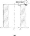
- Fig. 3 is a schematic diagram illustrating the forming method of the embodiment, in which the rotatable support platform, the power supply and etc. are omitted for simplicity.
- the electric melting head is connected to the anode of the power supply and the substrate 202 is connected to the cathode.
- the processing parameters of the electric melting are as follows: the electric melting current is of 900A, the electric melting voltage is of 36V, the speed of the relative movement of the electric melting head 602 and the substrate is of 600-700 mm/min; the base material 202 is flat and has the same material as the raw wire.
- the electric melting method for forming a metal component is used to manufacture an annular metal component, the implementation steps is as below:
- the auxiliary material baffling device 130 which is lifted as the increasing of the formed deposited metal increasing is employed to support (undertake) the auxiliary material 302 so that the auxiliary material 302 is filled (baffled) at the outer side of the metal component, and therefore preventing the molten metal from overflow during the forming process.
- Common low-carbon steel H08A is selected as the raw wire and an electric melting method for forming metal components is used to vertically grow and manufacture a metal component with end socket by vertical growing.
- the apparatus used in the embodiment including:
- Fig. 4 is a schematic illustration of the electric melting method in the present embodiment, for simplicity, the apparatus are omitted in the Fig..
- the selected parameters are as follows: the diameter of the wire bar is of 5mm; the auxiliary material has 30% of Iron powder is adding into a standard fused flux SJ101; the electric melting current is of 900A, the electric melting voltage is of 40V, electric melting head 403 is connected to the anode of the power supply and the substrate 203 is connected to the cathode; the speed for feeding the wire is of 2200 mm/min; the linear speed of the rotation is of 750 mm.
- the electric melting method is used to form a irregularly shaped workpiece(end socket). Because 30% iron powder is introduced during the production, the forming efficiency is greatly improved.
- the integral formation of a cylinder of an evaporator illustrates an electric melting method for integrally forming a cylinder of a nuclear power evaporator.
- the whole cylinder may be divided into six sections (two upper sections, three lower sections, and one cone section). The six sections are forged respectively first, and then being assembly welded.
- the material of the cylinder is low-alloy steel SA508Gr3CL2. After the cylinder is formed, the inner wall of which needs build-up welding with the 308 stainless steel having a thickness of about 8 mm.
- the cylinder can be integrally formed in a single time.
- the apparatus used by the present method includes:
- Fig. 5 is a schematic illustration of the electric melting method according to the present embodiment, in which the power supply, the automatic wire feeder and etc. are omitted for simplicity.
- Fig. 2 there are specialized low carbon steel with a diameter of 5 mm that is selected as the raw wire 104 (C: 0.11-0.12%; other elements is consistent with SA508-3); specialized auxiliary material (compositions of which are 29.5% CaO+MgO; 30% Al 2 O 3_ +MnO; 20.5% SiO 2 +TiO; 20% CaF 2 ); twenty one electric melting heads 404; DC power supply.
- the electric melting heads 404 are connected to the cathode of the power supply and the base material 201 is connected to the anode.
- the process parameters are as follows: the electric melting current is of 900A, the electric melting voltage is of 42V, and the speed of the relative movement of the electric melting heads 404 and the base material 204 is of 600-700 mm/min; the base material 204 is a formed cylinder of 308 stainless steel.
- the electric melting method for forming metal components is employed to manufacture an annular metal component, the implementation steps are as follows:
- the base material 204 of stainless steel becomes a part of the cylinder of the container, such that different materials are used to form the cylinder directly that changes the traditional process which forges SA508-3 cylinder first and build-up welds the 308 stainless steel on the inner wall.
- the traditional process that carries out forging in sections first and build-up welding afterwards is changed. As such, the process and procedure are simplified and the working efficiency and quality are improved.
Landscapes
- Engineering & Computer Science (AREA)
- Chemical & Material Sciences (AREA)
- Materials Engineering (AREA)
- Manufacturing & Machinery (AREA)
- Mechanical Engineering (AREA)
- Physics & Mathematics (AREA)
- Optics & Photonics (AREA)
- Plasma & Fusion (AREA)
- Health & Medical Sciences (AREA)
- Microelectronics & Electronic Packaging (AREA)
- Toxicology (AREA)
- Composite Materials (AREA)
- Ceramic Engineering (AREA)
- Furnace Details (AREA)
- Manufacture Of Metal Powder And Suspensions Thereof (AREA)
- Pressure Welding/Diffusion-Bonding (AREA)
Applications Claiming Priority (2)
| Application Number | Priority Date | Filing Date | Title |
|---|---|---|---|
| CN201410617953.2A CN104526171B (zh) | 2014-11-04 | 2014-11-04 | 金属构件电熔成形方法 |
| PCT/CN2015/093636 WO2016070778A1 (fr) | 2014-11-04 | 2015-11-03 | Procédé de fusion électrique pour la formation d'une structure métallique |
Publications (2)
| Publication Number | Publication Date |
|---|---|
| EP3213863A1 true EP3213863A1 (fr) | 2017-09-06 |
| EP3213863A4 EP3213863A4 (fr) | 2017-12-13 |
Family
ID=52841899
Family Applications (1)
| Application Number | Title | Priority Date | Filing Date |
|---|---|---|---|
| EP15856920.2A Withdrawn EP3213863A4 (fr) | 2014-11-04 | 2015-11-03 | Procédé de fusion électrique pour la formation d'une structure métallique |
Country Status (4)
| Country | Link |
|---|---|
| US (1) | US20170320277A1 (fr) |
| EP (1) | EP3213863A4 (fr) |
| CN (1) | CN104526171B (fr) |
| WO (1) | WO2016070778A1 (fr) |
Cited By (4)
| Publication number | Priority date | Publication date | Assignee | Title |
|---|---|---|---|---|
| EP3492617A1 (fr) * | 2017-11-29 | 2019-06-05 | Lincoln Global, Inc. | Procédés et compositions pour la fabrication d'un article de forme presque nette |
| EP3502298A1 (fr) * | 2017-11-29 | 2019-06-26 | Lincoln Global, Inc. | Procédés et compositions pour la fabrication d'un article de forme presque nette |
| US10933492B2 (en) | 2017-11-29 | 2021-03-02 | Lincoln Global, Inc. | Systems and methods of additive structural build techniques |
| US11229953B2 (en) | 2017-11-29 | 2022-01-25 | Lincoln Global, Inc. | Methods and systems for additive manufacturing |
Families Citing this family (27)
| Publication number | Priority date | Publication date | Assignee | Title |
|---|---|---|---|---|
| CN104526171B (zh) * | 2014-11-04 | 2016-10-12 | 南方增材科技有限公司 | 金属构件电熔成形方法 |
| HK1245719B (zh) | 2014-12-12 | 2019-10-25 | Digital Alloys Incorporated | 金属结构的增材制造 |
| KR101614860B1 (ko) * | 2015-10-26 | 2016-04-25 | 비즈 주식회사 | 아크 및 합금금속분말 코어 와이어를 이용한 ded 아크 3차원 합금금속분말 프린팅 방법 및 그 장치 |
| CN105880598B (zh) * | 2016-06-03 | 2018-02-09 | 梁福鹏 | 一种金属三维打印方法及其设备 |
| CN106271142A (zh) * | 2016-08-31 | 2017-01-04 | 南方增材科技有限公司 | 超超临界高中压转子电熔成形方法 |
| CN106271141A (zh) * | 2016-08-31 | 2017-01-04 | 南方增材科技有限公司 | 核电常规岛低压转子电熔成形方法 |
| DE102016117540A1 (de) | 2016-09-16 | 2018-03-22 | Joomion UG (haftungsbeschränkt) | Verfahren und Vorrichtung zum kontinuierlichen elektrischen Schmelzen, Vermischen und Extrudieren von Metallen und anderen leitfähigen Materialien |
| JP6822881B2 (ja) * | 2017-03-27 | 2021-01-27 | 株式会社神戸製鋼所 | 積層造形物の製造方法及び製造システム |
| WO2019054423A1 (fr) * | 2017-09-15 | 2019-03-21 | 株式会社神戸製鋼所 | Moulage stratifié et procédé de fabrication d'un moulage stratifié |
| CN107598407A (zh) * | 2017-11-09 | 2018-01-19 | 湖州高恒电梯配件有限公司 | 一种堆焊焊接方法 |
| CN107855677A (zh) * | 2017-11-09 | 2018-03-30 | 湖州高恒电梯配件有限公司 | 电梯导靴板的焊接方法 |
| CN108247051B (zh) * | 2017-12-28 | 2019-11-08 | 南方增材科技有限公司 | 一种用于电熔成形的集成枪架系统 |
| CN108188542A (zh) * | 2017-12-28 | 2018-06-22 | 南方增材科技有限公司 | 金属构件丝极电熔增材制造方法及金属构件 |
| DE102018004337A1 (de) * | 2018-05-30 | 2019-12-05 | Rosswag Gmbh | Verfahren zur Entwicklung von Schmiedewerkstoffen |
| CA3101061A1 (fr) | 2018-06-20 | 2019-12-26 | Digital Alloys Incorporated | Devidoir multi-diametre |
| CN108971697A (zh) * | 2018-06-29 | 2018-12-11 | 中广核核电运营有限公司 | 核电站sap制冷机端盖电熔增材制造方法 |
| US11426818B2 (en) | 2018-08-10 | 2022-08-30 | The Research Foundation for the State University | Additive manufacturing processes and additively manufactured products |
| JP7183120B2 (ja) * | 2019-06-14 | 2022-12-05 | 株式会社神戸製鋼所 | 造形物の製造方法、積層制御装置、プログラム |
| US11853033B1 (en) | 2019-07-26 | 2023-12-26 | Relativity Space, Inc. | Systems and methods for using wire printing process data to predict material properties and part quality |
| CN110523980B (zh) * | 2019-08-14 | 2024-03-01 | 中国石油天然气集团有限公司 | 一种三通管件的电熔增材制造方法 |
| EP3822015A1 (fr) | 2019-11-18 | 2021-05-19 | FRONIUS INTERNATIONAL GmbH | Procédé de balayage de la surface des pièces métalliques |
| CN111761181A (zh) * | 2020-07-07 | 2020-10-13 | 天津大学 | 一种大幅提高构件低温韧性的埋弧增材制造方法 |
| CN111922480A (zh) * | 2020-07-24 | 2020-11-13 | 中国航空工业集团公司沈阳飞机设计研究所 | 一种部件的连接方法 |
| CN113118467B (zh) * | 2021-04-16 | 2022-08-05 | 青岛科技大学 | 一种打印装置及打印方法 |
| DE202021003407U1 (de) | 2021-11-04 | 2021-12-08 | Christian Banzhaf | Modularer Hochofen |
| CN116890101B (zh) * | 2023-05-30 | 2026-04-14 | 中国人民解放军海军工程大学 | 一种利用电渣热熔化成分变化药芯丝材快速制备大尺寸异种金属梯度材料的方法 |
| CN117324643B (zh) * | 2023-09-21 | 2024-05-17 | 华中科技大学 | 多束激光同步熔丝沉积-送粉熔覆熔池形态调控方法 |
Family Cites Families (46)
| Publication number | Priority date | Publication date | Assignee | Title |
|---|---|---|---|---|
| US3097979A (en) * | 1960-12-05 | 1963-07-16 | Union Carbide Corp | Magnetic flux-gas shielded metal arc welding |
| US3885922A (en) * | 1972-05-22 | 1975-05-27 | Arcos Corp | Pressure vessel and bimetallic components |
| US4086463A (en) * | 1972-11-13 | 1978-04-25 | Tsukishima Kikai Co., Ltd. | Flux-cored wire |
| IT1004255B (it) * | 1973-04-19 | 1976-07-10 | August Rhyssen Hutte Ag | Procedimento e dispositivo per la produzione di parti strutturali di grandi dimensioni |
| CH594471A5 (fr) * | 1976-07-02 | 1978-01-13 | Bbc Brown Boveri & Cie | |
| US4228337A (en) * | 1979-05-03 | 1980-10-14 | Allis-Chalmers Corporation | Method of electroslag welding |
| US4503316A (en) * | 1981-08-13 | 1985-03-05 | Kabushiki Kaisha Kobe Seiko Sho | DC Welding power supply system |
| US4508953A (en) * | 1982-04-27 | 1985-04-02 | Kabushiki Kaisha Kobe Seiko Sho | Method of multi-layer welding |
| CH664109A5 (de) * | 1984-12-14 | 1988-02-15 | Sulzer Ag | Verfahren zur herstellung eines zylindrischen hohlkoerpers und anlage zum durchfuehren des verfahrens. |
| CA2037660C (fr) * | 1990-03-07 | 1997-08-19 | Tadashi Kamimura | Methodes de modification de l'etat de surface d'articles metalliques et appareils correspondants |
| DE69424573T2 (de) * | 1993-09-20 | 2001-01-18 | Nippon Steel Corp., Tokio/Tokyo | Stahlplatte mit niedriger schweissspannung und guter biegbarkeit bei linearer aufheizung, herstellungsverfahren, schweissmaterial und dessen herstellungsverfahren |
| EP0665079B1 (fr) * | 1994-01-29 | 1999-01-07 | Asea Brown Boveri Ag | Procédé pour reliér pièces métalliques au moyen d'un soudage par fusion à l'arc |
| US6069333A (en) * | 1997-02-21 | 2000-05-30 | Lincoln Global, Inc. | Method and system for welding railroad rails |
| US5945014A (en) * | 1998-01-05 | 1999-08-31 | Lincoln Global, Inc. | Method of arc welding heavy steel plates |
| US6069334A (en) * | 1998-07-06 | 2000-05-30 | Capitanescu; Dan | Electroslag strip overlay method |
| ES2156424T3 (es) * | 1998-07-18 | 2001-06-16 | Durum Verschleissschutz Gmbh | Electrodo de soldadura fungible y procedimiento para aplicar una capa de proteccion antidesgaste. |
| US6331694B1 (en) * | 1999-12-08 | 2001-12-18 | Lincoln Global, Inc. | Fuel cell operated welder |
| CN2590713Y (zh) * | 2002-12-05 | 2003-12-10 | 上海气焊机厂 | 全自动辊子堆焊机 |
| CN1272142C (zh) * | 2003-07-11 | 2006-08-30 | 西安交通大学 | 基于焊接堆积的多金属直接快速成型装置 |
| US7863538B2 (en) * | 2004-03-19 | 2011-01-04 | Hobart Brothers Company | Metal-core gas metal arc welding of ferrous steels with noble gas shielding |
| GB0418899D0 (en) * | 2004-08-24 | 2004-09-29 | Saipem Spa | Welding torch |
| US8266320B1 (en) * | 2005-01-27 | 2012-09-11 | Science Applications International Corporation | Computer network defense |
| US8242410B2 (en) * | 2006-07-14 | 2012-08-14 | Lincoln Global, Inc. | Welding methods and systems |
| CN100434222C (zh) * | 2006-08-10 | 2008-11-19 | 上海人造板机器厂有限公司 | 大直径辊体的焊接方法及装置 |
| CN1947911A (zh) * | 2006-11-09 | 2007-04-18 | 上海锅炉厂有限公司 | 筒体表面圆形凸缘埋弧自动堆焊工艺 |
| US9044818B2 (en) * | 2007-11-08 | 2015-06-02 | Lincoln Global, Inc. | Method of welding two sides of a joint simultaneously |
| US20100089977A1 (en) * | 2008-10-14 | 2010-04-15 | Gm Global Technology Operations, Inc. | Friction stir welding of dissimilar metals |
| US8816238B2 (en) * | 2009-06-03 | 2014-08-26 | William L. Bong | Electroslag welding with variable balance, constant potential, alternating current, square wave welding power supply |
| EP2322313A1 (fr) * | 2009-11-13 | 2011-05-18 | Siemens Aktiengesellschaft | Procédé de soudure de pièces usinées en superalliages résistant aux températures avec un débit particulier du matériau d'apport de soudage |
| WO2012096937A1 (fr) * | 2011-01-10 | 2012-07-19 | Arcelormittal Investigacion Y Desarrollo S.L. | Procédé de soudage d'aluminure de nickel |
| CN102962547B (zh) * | 2012-11-23 | 2015-06-03 | 首都航天机械公司 | 一种钛合金结构件电弧增材制造方法 |
| CN103009015B (zh) * | 2013-01-13 | 2015-01-07 | 邯郸市永固冶金备件有限公司 | 双金属复合耐磨冶金轧辊的制造方法 |
| CN103203529B (zh) * | 2013-03-28 | 2015-12-09 | 北京工业大学 | 非熔化极电弧与双丝熔化极电弧交叉耦合的焊接方法 |
| JP2015038237A (ja) * | 2013-08-19 | 2015-02-26 | 独立行政法人産業技術総合研究所 | 積層造形物、粉末積層造形装置及び粉末積層造形方法 |
| US9358629B1 (en) * | 2013-09-24 | 2016-06-07 | Siemens Energy, Inc. | Tungsten submerged arc welding using powdered flux |
| US10046419B2 (en) * | 2014-01-24 | 2018-08-14 | Lincoln Global, Inc. | Method and system for additive manufacturing using high energy source and hot-wire |
| CN104526170B (zh) * | 2014-11-04 | 2016-11-02 | 南方增材科技有限公司 | 超超临界高中压转子电熔成形方法 |
| CN104526115B (zh) * | 2014-11-04 | 2017-01-18 | 南方增材科技有限公司 | 核电站压力容器筒体电熔成形方法 |
| CN104526172B (zh) * | 2014-11-04 | 2016-08-17 | 南方增材科技有限公司 | 核电常规岛低压转子电熔成形方法 |
| CN104532236B (zh) * | 2014-11-04 | 2017-05-31 | 南方增材科技有限公司 | 核电站稳压器筒体电熔成形方法 |
| CN104526167B (zh) * | 2014-11-04 | 2016-08-17 | 南方增材科技有限公司 | 加氢反应器筒体电熔成形方法 |
| CN104526169B (zh) * | 2014-11-04 | 2016-08-17 | 南方增材科技有限公司 | 核电站蒸发器筒体电熔成形方法 |
| CN104526168B (zh) * | 2014-11-04 | 2016-11-16 | 南方增材科技有限公司 | 一种电熔成形超低碳超细晶合金钢材料 |
| CN104526171B (zh) * | 2014-11-04 | 2016-10-12 | 南方增材科技有限公司 | 金属构件电熔成形方法 |
| CN104526113B (zh) * | 2014-11-04 | 2016-08-31 | 南方增材科技有限公司 | 超超临界低压转子的电熔成形方法 |
| CN104651834B (zh) * | 2014-11-21 | 2017-05-31 | 南方增材科技有限公司 | Cap1400主蒸汽管贯穿件电熔成形方法 |
-
2014
- 2014-11-04 CN CN201410617953.2A patent/CN104526171B/zh active Active
-
2015
- 2015-11-03 EP EP15856920.2A patent/EP3213863A4/fr not_active Withdrawn
- 2015-11-03 US US15/524,274 patent/US20170320277A1/en not_active Abandoned
- 2015-11-03 WO PCT/CN2015/093636 patent/WO2016070778A1/fr not_active Ceased
Cited By (5)
| Publication number | Priority date | Publication date | Assignee | Title |
|---|---|---|---|---|
| EP3492617A1 (fr) * | 2017-11-29 | 2019-06-05 | Lincoln Global, Inc. | Procédés et compositions pour la fabrication d'un article de forme presque nette |
| EP3502298A1 (fr) * | 2017-11-29 | 2019-06-26 | Lincoln Global, Inc. | Procédés et compositions pour la fabrication d'un article de forme presque nette |
| US10933492B2 (en) | 2017-11-29 | 2021-03-02 | Lincoln Global, Inc. | Systems and methods of additive structural build techniques |
| US11229953B2 (en) | 2017-11-29 | 2022-01-25 | Lincoln Global, Inc. | Methods and systems for additive manufacturing |
| US11980968B2 (en) | 2017-11-29 | 2024-05-14 | Lincoln Global, Inc. | Methods and systems for additive tool manufacturing |
Also Published As
| Publication number | Publication date |
|---|---|
| WO2016070778A1 (fr) | 2016-05-12 |
| EP3213863A4 (fr) | 2017-12-13 |
| CN104526171A (zh) | 2015-04-22 |
| US20170320277A1 (en) | 2017-11-09 |
| CN104526171B (zh) | 2016-10-12 |
Similar Documents
| Publication | Publication Date | Title |
|---|---|---|
| EP3213863A1 (fr) | Procédé de fusion électrique pour la formation d'une structure métallique | |
| EP3216549A1 (fr) | Procédé de fusion électrique pour former un cylindre de cuve sous pression de centrale nucléaire | |
| JP7002142B2 (ja) | 付加製造過程で部品の変形及び精度を並行制御する方法 | |
| Rodrigues et al. | Ultracold-Wire and arc additive manufacturing (UC-WAAM) | |
| US11951560B2 (en) | Wire and arc additive manufacturing method for titanium alloy | |
| CN102240860B (zh) | 梯度材料模具制造方法及设备 | |
| WO2016070780A1 (fr) | Procédé de soudage à l'arc submergé pour la formation d'une structure métallique | |
| CN104526167B (zh) | 加氢反应器筒体电熔成形方法 | |
| US20170145586A1 (en) | System and method for single crystal growth with additive manufacturing | |
| WO2016070777A1 (fr) | Procédé de fusion électrique pour la formation de cylindre évaporateur d'une centrale nucléaire | |
| WO2016070779A1 (fr) | Procédé de fusion électrique pour former un cylindre régulateur de tension de centrale nucléaire | |
| CN101239413B (zh) | 废旧模具电磁堆焊修复和表面改性方法与设备 | |
| CN115582555B (zh) | 增材制造复合搅拌摩擦处理有序构筑超细晶网络结构的方法 | |
| CN104526168B (zh) | 一种电熔成形超低碳超细晶合金钢材料 | |
| CN111112793A (zh) | 一种镁合金结构件的电弧增材制造方法及其所用设备 | |
| CN112517659A (zh) | 一种等离子弧/电弧增材制造用钛合金丝材加工方法 | |
| CN108067706A (zh) | 金属构件的增材制造设备 | |
| Ren et al. | A comprehensive review on the Wire-Arc DED austenitic stainless steel: advanced technologies, microstructure, defect issues, enhancing properties | |
| KR20250042169A (ko) | 탄탈룸-텅스텐 합금 제품 및 이의 제조 방법 | |
| CN117548778A (zh) | 一种大型金属构件的电弧增材成形方法 | |
| CN110523980B (zh) | 一种三通管件的电熔增材制造方法 | |
| CN205324942U (zh) | 一种自动氩弧焊堆焊装置 | |
| KR100383425B1 (ko) | 3차원 용접과 밀링을 이용한 시작 금형 인서트의 제조방법 및 장치 | |
| WO2019243088A1 (fr) | Procédé et dispositif de formage de pièces métalliques | |
| KR102487431B1 (ko) | 와이어 아크 3d 적층법으로 제조한 알루미늄 다이캐스팅 금형의 제조방법 |
Legal Events
| Date | Code | Title | Description |
|---|---|---|---|
| PUAI | Public reference made under article 153(3) epc to a published international application that has entered the european phase |
Free format text: ORIGINAL CODE: 0009012 |
|
| 17P | Request for examination filed |
Effective date: 20170601 |
|
| AK | Designated contracting states |
Kind code of ref document: A1 Designated state(s): AL AT BE BG CH CY CZ DE DK EE ES FI FR GB GR HR HU IE IS IT LI LT LU LV MC MK MT NL NO PL PT RO RS SE SI SK SM TR |
|
| AX | Request for extension of the european patent |
Extension state: BA ME |
|
| A4 | Supplementary search report drawn up and despatched |
Effective date: 20171109 |
|
| RIC1 | Information provided on ipc code assigned before grant |
Ipc: B23K 11/00 20060101ALI20171103BHEP Ipc: B23K 9/18 20060101ALI20171103BHEP Ipc: B23K 28/02 20140101AFI20171103BHEP Ipc: B23K 9/04 20060101ALI20171103BHEP Ipc: B23K 25/00 20060101ALI20171103BHEP Ipc: B29C 64/141 20170101ALI20171103BHEP Ipc: B33Y 10/00 20150101ALI20171103BHEP |
|
| DAV | Request for validation of the european patent (deleted) | ||
| DAX | Request for extension of the european patent (deleted) | ||
| 17Q | First examination report despatched |
Effective date: 20181012 |
|
| STAA | Information on the status of an ep patent application or granted ep patent |
Free format text: STATUS: THE APPLICATION HAS BEEN WITHDRAWN |
|
| 18W | Application withdrawn |
Effective date: 20181207 |